EP4403713B1 - Installation sanitaire, notamment douche - Google Patents
Installation sanitaire, notamment douche Download PDFInfo
- Publication number
- EP4403713B1 EP4403713B1 EP24152648.2A EP24152648A EP4403713B1 EP 4403713 B1 EP4403713 B1 EP 4403713B1 EP 24152648 A EP24152648 A EP 24152648A EP 4403713 B1 EP4403713 B1 EP 4403713B1
- Authority
- EP
- European Patent Office
- Prior art keywords
- pump
- sanitary installation
- water
- heat exchanger
- installation according
- Prior art date
- Legal status (The legal status is an assumption and is not a legal conclusion. Google has not performed a legal analysis and makes no representation as to the accuracy of the status listed.)
- Active
Links
Images

Classifications
-
- E—FIXED CONSTRUCTIONS
- E03—WATER SUPPLY; SEWERAGE
- E03C—DOMESTIC PLUMBING INSTALLATIONS FOR FRESH WATER OR WASTE WATER; SINKS
- E03C1/00—Domestic plumbing installations for fresh water or waste water; Sinks
- E03C1/02—Plumbing installations for fresh water
- E03C1/04—Water-basin installations specially adapted to wash-basins or baths
- E03C1/0408—Water installations especially for showers
-
- E—FIXED CONSTRUCTIONS
- E03—WATER SUPPLY; SEWERAGE
- E03C—DOMESTIC PLUMBING INSTALLATIONS FOR FRESH WATER OR WASTE WATER; SINKS
- E03C1/00—Domestic plumbing installations for fresh water or waste water; Sinks
- E03C1/02—Plumbing installations for fresh water
- E03C1/04—Water-basin installations specially adapted to wash-basins or baths
- E03C1/044—Water-basin installations specially adapted to wash-basins or baths having a heating or cooling apparatus in the supply line
-
- F—MECHANICAL ENGINEERING; LIGHTING; HEATING; WEAPONS; BLASTING
- F24—HEATING; RANGES; VENTILATING
- F24D—DOMESTIC- OR SPACE-HEATING SYSTEMS, e.g. CENTRAL HEATING SYSTEMS; DOMESTIC HOT-WATER SUPPLY SYSTEMS; ELEMENTS OR COMPONENTS THEREFOR
- F24D17/00—Domestic hot-water supply systems
- F24D17/0005—Domestic hot-water supply systems using recuperation of waste heat
-
- F—MECHANICAL ENGINEERING; LIGHTING; HEATING; WEAPONS; BLASTING
- F24—HEATING; RANGES; VENTILATING
- F24D—DOMESTIC- OR SPACE-HEATING SYSTEMS, e.g. CENTRAL HEATING SYSTEMS; DOMESTIC HOT-WATER SUPPLY SYSTEMS; ELEMENTS OR COMPONENTS THEREFOR
- F24D17/00—Domestic hot-water supply systems
- F24D17/0036—Domestic hot-water supply systems with combination of different kinds of heating means
- F24D17/0052—Domestic hot-water supply systems with combination of different kinds of heating means recuperated waste heat and conventional heating means
-
- E—FIXED CONSTRUCTIONS
- E03—WATER SUPPLY; SEWERAGE
- E03C—DOMESTIC PLUMBING INSTALLATIONS FOR FRESH WATER OR WASTE WATER; SINKS
- E03C1/00—Domestic plumbing installations for fresh water or waste water; Sinks
- E03C1/12—Plumbing installations for waste water; Basins or fountains connected thereto; Sinks
- E03C1/22—Outlet devices mounted in basins, baths, or sinks
-
- E—FIXED CONSTRUCTIONS
- E03—WATER SUPPLY; SEWERAGE
- E03C—DOMESTIC PLUMBING INSTALLATIONS FOR FRESH WATER OR WASTE WATER; SINKS
- E03C1/00—Domestic plumbing installations for fresh water or waste water; Sinks
- E03C2001/005—Installations allowing recovery of heat from waste water for warming up fresh water
-
- F—MECHANICAL ENGINEERING; LIGHTING; HEATING; WEAPONS; BLASTING
- F28—HEAT EXCHANGE IN GENERAL
- F28D—HEAT-EXCHANGE APPARATUS, NOT PROVIDED FOR IN ANOTHER SUBCLASS, IN WHICH THE HEAT-EXCHANGE MEDIA DO NOT COME INTO DIRECT CONTACT
- F28D21/00—Heat-exchange apparatus not covered by any of the groups F28D1/00 - F28D20/00
- F28D21/0001—Recuperative heat exchangers
- F28D21/0012—Recuperative heat exchangers the heat being recuperated from waste water or from condensates
Definitions
- the invention relates to a sanitary installation which is particularly designed as a shower.
- Heat recovery from, for example, shower wastewater can significantly reduce the energy demand for hot water. If heat exchangers are placed below the shower level in the floor structure, only a relatively small portion of the waste heat can be recovered, as the heat exchanger must be dimensioned accordingly.
- the heat exchangers are placed to the side of the shower rather than below the shower tray, allowing them to be dimensioned accordingly.
- these systems require a lift pump (hereinafter referred to as the "pump”) to pump the warm shower wastewater to the heat exchanger, thus preheating the cold fresh water.
- WO 2018 / 169 394 A1 Describes a shower system in which wastewater is applied to coils of a heat exchanger pipe to preheat incoming cold water.
- a pump is provided for this purpose, which conveys the wastewater, with the pump speed being electronically controlled depending on the water flow.
- a bypass is installed, which leads back to the shower tray via a T-piece between the pump and the heat exchanger.
- the bypass has a level-controlled valve that keeps the bypass open as long as too little wastewater has been collected and closes the bypass when there is sufficient wastewater. With discontinuous on-off control, the amount of wastewater reaching the heat exchanger fluctuates, which reduces the efficiency of the heat exchanger.
- the utility model DE 20 2006 001 996 U1 refers to a device for recovering heat from wastewater from a shower and/or bathing facility.
- the wastewater flow rate which is pumped to the heat exchanger by a pump, is varied using a valve.
- the valve is controlled by a float.
- the valve is located in the pressure line and thus downstream (after) the pump.
- the wastewater reservoir in the device shown must be relatively deep so that the pump head can fill with water automatically. This, in turn, results in a relatively high base structure.
- the object of the present invention is to provide a sanitary installation, in particular a shower, which can be operated as energy-efficiently as possible while being simple to manufacture and requiring little maintenance.
- the invention thus shows a sanitary facility.
- the sanitary facility is designed in particular as a shower and will usually be explained in more detail below using this example.
- the wastewater used for heat recovery can, for example, come from one or more sinks, a washing machine or a dishwasher instead of one or more showers.
- the used wastewater is used for heat recovery within the same sanitary facility; for example, the wastewater from the shower(s) is reused to heat the fresh water of the same shower(s).
- the wastewater from one sanitary facility can be used to heat the fresh water of another sanitary facility.
- the sanitary installation according to the invention shows a collecting device with a drain opening.
- the drain opening is located at the bottom of the collecting device.
- the top of the collecting device is preferably closed with a water-permeable cover, in particular a mesh cover.
- the collection device is designed, in particular, as a basin positioned so that wastewater from a shower tray flows into the collection device. If there is no shower tray (for example, the wastewater drains onto a tiled or concrete shower floor), the collection device can be positioned accordingly so that the water flows from the shower floor into the collection device.
- the sanitary system comprises a heat exchanger with a fresh water inlet.
- the heat exchanger is positioned, in particular, next to and not below the collecting device. Furthermore, it is particularly provided that the heat exchanger is positioned above the collecting device; i.e., that at least part of the heat exchanger is arranged higher than the collecting device. This enables the use of a correspondingly large heat exchanger.
- the heat exchanger has a fresh water outlet next to the fresh water inlet.
- the supplied cold fresh water flows through the heat exchanger, in particular along a spiral pipe, from the fresh water inlet to the fresh water outlet.
- the fresh water outlet is preferably connected to a water outlet. This water outlet, in turn, is designed, in particular, for connecting a shower head.
- further components such as a water heater and/or a fitting, can be located between the fresh water outlet of the heat exchanger and the water outlet.
- the described collecting device is located on the same sanitary facility, in particular the shower, from which the heated fresh water is discharged via the water outlet, so that the fresh water passing through the heat exchanger is collected in the collecting device as waste water.
- the heat exchanger comprises a wastewater inlet and a wastewater outlet.
- the wastewater from the collection device can be introduced into the wastewater inlet of the heat exchanger. Inside the heat exchanger, the wastewater flows from the wastewater inlet to the wastewater outlet.
- the wastewater outlet of the heat exchanger is connected, in particular, to a wastewater discharge system (e.g., the building's sewer line).
- the sanitary system includes a connecting line for conveying the wastewater from the drain opening of the collection device to the heat exchanger, i.e., in particular, into the heat exchanger's predefined wastewater inlet.
- This connecting line in particular, includes hoses and/or pipes for conveying the wastewater accordingly.
- a pump is located in the connecting line.
- This pump can also be referred to as a lift pump or sewage pump. It is specifically intended that the pump be positioned higher than the drain opening. In particular, the pump is not located below the collecting device, but next to it.
- the term "next to the collecting device” also includes a pump arrangement "to the side of the collecting device and higher than the collecting device.” This results in a very flat floor structure for the sanitary facility. Only the collecting device determines the depth of the structure, since the other large components such as the pump and heat exchanger are located to the side.
- a regulating arrangement is provided within the sanitary system according to the invention.
- This regulating arrangement regulates the water level in the collecting device. This ensures that the pump can be operated at a constant speed and, in particular, without speed regulation, and prevents air from being sucked in.
- the regulating arrangement is designed to change a flow cross-section depending on the water level in the collecting device. The wastewater flowing from the collecting device to the pump flows through this flow cross-section on the way between the collecting device and the pump. This is therefore a flow cross-section located between the collecting device and the pump.
- the regulating arrangement thus changes the flow cross-section in/on the suction line upstream of the pump (before the pump).
- the regulating arrangement in the suction line or at the beginning of the suction line has the advantage, among other things, that the mechanics used are more easily accessible - for example, for cleaning - than with an arrangement in the pressure line.
- the "change in the flow cross-section” specifically describes a continuous or multi-stage change in the flow cross-section, whereby the flow cross-section can assume multiple values greater than zero. In particular, it is not just a matter of opening and closing the flow cross-section.
- the regulating arrangement comprises a closure element that is movable in the drain opening to change the flow cross-section; in particular, it is movable up and down in the vertical direction.
- the closure element is a plug that is inserted into the drain opening.
- the closure element is movable upwards, i.e., out of the drain opening, to increase the flow cross-section, and downwards, i.e., into the drain opening, to decrease the flow cross-section.
- closure and/or the drain opening have a correspondingly tapered or widened cross-section.
- at least one of the two elements can be conical, rounded, conical, or truncated cone-shaped.
- the portion of the closure element which is inserted into the drain opening (also referred to as "protrusion") has a cross-section which decreases continuously or in sections downwards.
- the closure element is preferably arranged axially aligned with the drain opening.
- the regulating arrangement is designed to regulate the flow cross-section in a range of at least 5 mm 2 to at most 1000 mm 2 .
- the regulating arrangement preferably comprises a buoyancy body.
- This buoyancy body can also be referred to as a "float.”
- the buoyancy body is arranged in the collection device to float on the wastewater.
- the buoyancy body is coupled to the closure element in such a way that the closure element can be moved with the buoyancy body.
- the closure element can be firmly connected to the buoyancy body, or a one-piece design of the closure element and buoyancy body can be provided. In a preferred embodiment, however, the closure element is provided so that it can be displaced within the buoyancy body, abutting on one side. In particular, it is provided that the closure element itself does not float and thus sinks downwards into the drain opening without buoyancy from the buoyancy body. However, since the closure element is arranged in the buoyancy body with a "single-sided impact," the closure element can be lifted by the buoyancy body, but on the other hand, the buoyancy body can sink further once the closure element is seated in the drain opening. This ensures that the buoyancy body always remains on the surface of the wastewater in the collection device, even at very low water levels. This in turn ensures that the surface of the wastewater is covered as much as possible, thus preventing air ingress wherever possible.
- the lowerable float is that—in combination with the switch described below—it can deactivate the pump via the integrated sensor only when the water level is very low. If the float could not lower further with the water level, the pump would have to be deactivated before the closure element fully engages the drain opening.
- the buoyancy body covers at least 50%, preferably at least 80%, and more preferably at least 90%, of the water surface in the collection device. Such a large buoyancy body largely covers the water surface in the collection device, thereby preventing air from entering the drain opening as much as possible.
- a sensor is arranged on the buoyancy body or on the closure element.
- the sensor is designed to activate the switch.
- the switch, or at least a part of the switch is located on the collecting device or next to the collecting device, so that the buoyancy body, together with the sensor, can be moved past the switch as the water level changes.
- the sensor in particular, has a magnetic element.
- the magnetic element can be a permanent magnet or a magnetic material (e.g., iron).
- the switch is designed to detect the magnetic element.
- the sensor can also be a region of the buoyancy body or closure element that otherwise actuates a mechanical or optical switch.
- the switch can basically be designed in such a way that when the sensor is detected, the condition for switching the pump on or off is met - whether the state of the pump is then actually changed can depend on a flow switch, which will be described later.
- the switch has a detection range within which it can detect the presence of the sensor.
- the switch is preferably configured such that the condition for switching the pump on (or leaving it switched on) is met as long as the sensor is within the detection range. And the condition for switching the pump off (or leaving it switched off) is met as long as the sensor is not within the detection range.
- a flow switch is preferably provided, which is arranged to detect a water flow of fresh water.
- the flow switch can be located, for example, upstream of the fresh water inlet of the heat exchanger or between the fresh water outlet of the heat exchanger and the water outlet.
- the switch on the collecting device and the flow switch are connected in series such that the pump only runs if the states of both switches indicate that the pump should be switched on.
- the flow switch is particularly designed to ensure that the condition for switching the pump on is met when the water flow exceeds a first threshold and for switching the pump off when the water flow falls below a second threshold.
- the two thresholds can generally be the same or different.
- the advantage of the switch on the collection device in combination with the flow switch is particularly evident when the pump only runs when both switches are activated – i.e., the condition for switching on the pump is present at both switches. Otherwise, backflowing wastewater from the connecting line could raise the water level in the collection device after the shower. The pump would then be reactivated due to the switch on the collection device until the water level drops. When the pump is switched off, water would flow from the connecting line back into the collection tank, and the pump would be reactivated. This could lead to constant "oscillation.” This oscillation can be avoided by the flow switch.
- the pump is designed as a centrifugal pump.
- centrifugal pumps are simple to manufacture and require very little maintenance.
- centrifugal pumps are not self-priming, as they cannot build up negative pressure on the suction side as long as there is no liquid in the pump housing. This problem can be solved, however, by filling the pump housing and the connecting line between the collecting device and the pump with fluid before initial commissioning.
- the pump could be installed below the water level of the collecting device, although this should preferably be avoided in order to keep the installation height as low as possible.
- the pump in the sanitary facility can only be operated at a constant speed, which means that the pump can only be switched on and off, but its speed cannot be varied.
- a pump is used which, due to its design, can only be operated at a constant speed.
- the electrical and/or electronic systems of the sanitary facility can be designed so simply that the pump - regardless of its design - can only be operated at a constant speed and can therefore only be switched on and off. This enables the use of pumps that are easy to manufacture and require very little maintenance. At the same time, this simplifies the structure of the electrical and/or electronic systems of the sanitary facility.
- the regulating arrangement is designed so that, regardless of the water level in the collecting device, a minimum flow cross-section remains.
- the minimum flow area is greater than zero.
- this is achieved by ensuring that the closure element does not completely close the drain opening in its lower position.
- This can be achieved by designing the geometry of the drain opening and/or the closure element to ensure the minimum flow area when the closure element is seated in the drain opening.
- the closure element has/have at least one recess and/or the drain opening has/have at least one recess.
- This at least one recess is designed and positioned such that the minimum flow cross-section is ensured in the lowest position of the closure element.
- the minimum flow cross-section is preferably at least 5 mm 2 , particularly preferably at least 10 mm 2 .
- the upper limit of the minimum flow cross-section is preferably at most 80 mm 2 , more preferably at most 50 mm 2 .
- the connecting line between the pump and the heat exchanger has a siphon.
- This siphon can also be referred to as a tubular siphon.
- the lowest point of the siphon is preferably below a minimum water level in the collecting device. This minimum water level in the collecting device is determined in particular by the pump being switched off from this minimum water level, whereby the minimum water level in the collecting device is maintained.
- the siphon is positioned such that its lowest point is below a base of the collecting device.
- the riser section forms a reservoir above the pump with a capacity defined as the "first volume.”
- the connecting line has a corresponding capacity between the drain opening and the pump, defined as the “second volume.”
- the first volume is preferably larger than the second volume. If water flows back from this second volume toward the collection device, there will always be enough water in the first volume to keep the pump completely filled.
- the collection device has an overflow connected to the wastewater outlet. This prevents the collection device from overflowing, as excess wastewater can be discharged directly via the overflow.
- the sanitary facility comprises only the described heat exchanger and no additional water heater. Instead, the sanitary facility is connected to the hot water pipe of a building.
- the sanitary facility has a fitting for mixing the heated fresh water from the fresh water outlet of the heat exchanger with the incoming hot water.
- This fitting can be, for example, a conventional shower mixer.
- the water heater is designed to be located downstream of the fresh water outlet of the heat exchanger. The water heater thus further heats the water already preheated in the heat exchanger.
- the sanitary facility not have a hot water connection on the building's side. Only a cold water connection is provided, which leads to the fresh water supply of the heat exchanger.
- the heated water from the heat exchanger i.e., downstream of the heat exchanger's fresh water outlet, is split into two lines.
- One line passes through the water heater and is thus further heated before flowing to the tap.
- the other line flows directly from the fresh water outlet to the tap.
- the two lines can then be mixed together in the tap, allowing the desired temperature of the water exiting the water outlet to be adjusted.
- a return line is preferably provided, which branches off downstream of the water heater and leads to the fresh water inlet of the heat exchanger.
- this return line contains another pump and/or another check valve.
- This return line can also be referred to as part of a preheating circuit. This has proven helpful when the water heater has a relatively low heating output, which is insufficient to bring the cold fresh water to the desired temperature without heat recovery in the heat exchanger. This can be particularly useful at the beginning of the shower cycle when the fresh water is not yet preheated.
- the invention is not limited to a specific type of heat exchanger.
- the heat exchanger has a height, this height is the largest dimension of the heat exchanger, and the height is aligned vertically. This allows a substantial portion of the overall height of the sanitary facility, in particular the shower, to be used for the heat exchanger.
- the heat exchanger has a further dimension perpendicular to its height—in particular width, length, or diameter.
- the height is at least five times, in particular at least ten times, as large as the further dimension.
- the heat exchanger is particularly preferably a double-pipe heat exchanger.
- the sanitary facility is designed as a shower for pre-wall installation.
- the sanitary facility comprises a frame.
- At least the collecting device including the regulating arrangement, the heat exchanger, the pump, and the connecting line are arranged on this frame.
- the described water heater and/or the fitting and/or the water outlet and/or the return line can also be located on the frame. It is also preferably provided that all other elements, such as the lines between the fresh water drain of the heat exchanger and the water outlet, are arranged on the frame.
- the frame including all components within it, can be mounted in front of or on an existing wall of a building. This ensures that the essential components of the sanitary system described here are located directly in the correct position, ensuring the system's functionality.
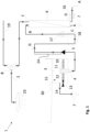
- the sanitary facility 1 has a water outlet 2 to which a shower head 23 is connected.
- the water from the shower head 23 flows via a shower tray into a collecting device 3 and is referred to below as wastewater.
- the collection device 3 is closed by a cover 15, for example, designed as a grid cover.
- the wastewater collects inside the collection device 3.
- a drain opening 4 At the bottom of the collection device is a drain opening 4. This is connected to a heat exchanger 6 via a connecting line G.
- the heat exchanger 6 has a fresh water inlet D and a wastewater outlet C on its underside.
- the fresh water inlet D can be connected to a cold water supply line A of a building.
- the wastewater outlet C leads to a wastewater outlet 7 of a building.
- a pipe leads from the fresh water outlet E to a fitting 8.
- the fresh water coming from the heat exchanger 6 can be mixed with warm water from a hot water supply line 19 and then fed to the water outlet 2 or the shower head 23.
- the hot water supply line 19 can supply warm water from any building-side hot water supply.
- the pump 5 is positioned higher than a base of the collecting device 3.
- the connecting line G has a riser section 24, after which the connecting line G descends to a siphon 18. Downstream of the siphon 18, the connecting line G rises again and ends at the wastewater inlet B of the heat exchanger 6.
- a return throttle 17, in particular designed as a check valve, can be located in the connecting line G.
- Fig. 1 a regulating arrangement 30.
- This regulating arrangement 30 comprises a closure element 11 that projects into the drain opening 4.
- the regulating arrangement 30 comprises a buoyancy body 10.
- the closure element 11 is slidably inserted into the buoyancy body 10. At its upper end, the closure element 11 has a collar so that it can be displaced relative to the buoyancy body 10, striking it on one side.
- the buoyancy body 10 floats upwards with the water level in the collecting device 3, the closure element 11 is also moved upwards. If the buoyancy body 10 sinks, the closure element 11, which is particularly designed to be non-floating, also sinks deeper into the drain opening 4.
- the flow cross-section in the outlet opening 4 can be changed by moving the closure element 11 up and down, as explained in the general part of the description.
- the regulating arrangement 30 comprises a switch 13 and a sensor 12.
- the switch 13 is located on the side of the collecting device 3.
- the sensor 12 is located on the buoyancy body 10.
- the sensor 12 is designed as a permanent magnet, which can be detected by the switch 13, designed as a magnetic switch.
- the switch 13 is positioned so that the sensor 12 is within its detection range as long as the water level in the collection device 3 is high enough. If the sensor 12 is within the detection range of the switch 13, the corresponding condition for switching on the pump 5 is met.
- a flow switch 16 is provided, which is located upstream of the fresh water inlet D of the heat exchanger 6. If a sufficient flow rate of fresh water is detected at the flow switch 16, the condition for switching on the pump 5 is also present on the part of the flow switch 16. In particular, it is provided that the pump 5 is switched on when the corresponding condition is met at the switch 13 and the flow switch 16. to switch on pump 5. If the condition no longer exists at one of the two switches 13, 16, pump 5 is switched off.
- Fig. 2 corresponds Fig. 1 except for the differences discussed below.
- Fig. 2 shows that instead of the hot water supply line 19 coming from the building, a water heater 9 can also be used within the sanitary facility 1.
- the functioning of the water heater 9 is explained in the general part of the description and also applies to the exemplary embodiment.
- the pipe coming from the fresh water drain E branches off and leads on the one hand directly to fitting 8 and on the other hand via the water heater 9 to fitting 8.
- a return line F can be used.
- This return line F branches off downstream of the water heater 9 and leads to the fresh water inlet D.
- Another pump and another check valve 21 can be used in the return line F.
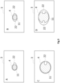
- Fig. 3 illustrates the minimum flow cross-section in the area of the drain opening 4. Accordingly, both the closure element 11 and the drain opening 4 can have a corresponding recess 22 with any geometry, so that even if the closure element 11 is located at the lowest point, the minimum flow cross-section is guaranteed.
- Example A in Fig. 3 illustrates that the recess 22 can be formed at the drain opening 4.
- Example B illustrates that several of these recesses 22 are also possible at the drain opening 4.
- Example C illustrates that the recess 22 can also be arranged on the closure element 11. According to Example D, several recesses 22 can be formed both at the drain opening 4 and on the closure element 11.
Landscapes
- Engineering & Computer Science (AREA)
- General Engineering & Computer Science (AREA)
- Chemical & Material Sciences (AREA)
- Thermal Sciences (AREA)
- Combustion & Propulsion (AREA)
- Mechanical Engineering (AREA)
- Physics & Mathematics (AREA)
- Health & Medical Sciences (AREA)
- Life Sciences & Earth Sciences (AREA)
- Hydrology & Water Resources (AREA)
- Public Health (AREA)
- Water Supply & Treatment (AREA)
- Details Of Fluid Heaters (AREA)
Claims (17)
- Installation sanitaire (1), en particulier douche, comprenant• un dispositif de collecte (3) avec un orifice de sortie (4) pour la collecte des eaux usées de l'installation sanitaire (1),• un échangeur de chaleur (6) avec une arrivée d'eau fraîche (D),• une conduite de liaison (G) pour acheminer les eaux usées de l'orifice de sortie (4) du dispositif de collecte (3) dans l'échangeur de chaleur (6) et• une pompe (5) dans la conduite de liaison (G),caractérisé en ce que l'installation sanitaire comprend en outre :
un ensemble de régulation (30) qui est réalisé pour modifier, en fonction d'un niveau d'eau dans le dispositif de collecte (3), une section transversale de débit, qui peut être traversée par les eaux usées du dispositif de collecte (3) vers la pompe (5). - Installation sanitaire selon la revendication 1, dans laquelle l'ensemble de régulation (30) comprend un élément de fermeture (11) qui peut être déplacé dans l'ouverture de sortie (4) pour modifier la section transversale de débit.
- Installation sanitaire selon la revendication 2, dans laquelle l'élément de régulation (30) comprend un corps flottant (10), qui est disposé dans le dispositif de collecte (3) pour flotter sur les eaux usées, dans laquelle le corps flottant (10) est couplé à l'élément de fermeture (11) pour déplacer l'élément de fermeture (11).
- Installation sanitaire selon la revendication 3, dans laquelle l'élément de fermeture (11) peut être coulissé d'un côté en butée dans le corps flottant (10) si bien que l'élément de fermeture (11) peut être soulevé par le corps flottant (10) et que le corps flottant (10) peut continuer à s'abaisser lors de la mise en place de l'élément de fermeture (11).
- Installation sanitaire selon l'une quelconque des revendications précédentes, dans laquelle l'ensemble de régulation comprend un interrupteur (13) pour actionner la pompe (5), en particulier pour mettre en marche et arrêter la pompe (5), dans laquelle l'interrupteur (13) peut être commuté en fonction du niveau d'eau dans le dispositif de collecte (3).
- Installation sanitaire selon la revendication 5 et l'une quelconque des revendications 3 ou 4, comprenant un transmetteur (12), en particulier un élément magnétique, pour commuter l'interrupteur (13), dans laquelle le transmetteur (12) est couplé au corps flottant (10), en particulier est disposé sur le corps flottant (10).
- Installation sanitaire selon l'une quelconque des revendications précédentes, dans laquelle la pompe (5), réalisée en particulier en tant que pompe centrifuge, ne peut fonctionner dans l'installation sanitaire (1) qu'à vitesse de rotation constante et ne peut donc qu'être mise en marche et arrêtée.
- Installation sanitaire selon l'une quelconque des revendications précédentes, comprenant un interrupteur de débit (16) pour détecter un débit d'eau propre, dans laquelle l'interrupteur de débit (16) actionne la pompe (5) en fonction du débit d'eau.
- Installation sanitaire selon l'une quelconque des revendications précédentes, dans laquelle l'ensemble de régulation (30) est réalisé pour laisser une section de débit minimal indépendante du niveau d'eau dans le dispositif de collecte (3).
- Installation sanitaire selon l'une quelconque des revendications précédentes, dans laquelle la conduite de liaison (G) entre la pompe (5) et l'échangeur thermique (6) présente un siphon (18) dont le point le plus bas se situe en dessous d'un niveau d'eau minimal dans le dispositif de collecte (3).
- Installation sanitaire selon l'une quelconque des revendications précédentes, dans laquelle la conduite de liaison (G) présente, en aval de la pompe (5), en particulier dans le cas d'une installation sanitaire selon la revendication 10 entre la pompe (5) et le siphon (18), une zone de colonne montante (24) ; de préférence dans laquelle la zone de colonne montante (24) offre un premier volume et la conduite de liaison (G) entre l'orifice de sortie (4) et la pompe (5) offre un deuxième volume, dans laquelle le premier volume est supérieur au deuxième volume.
- Installation sanitaire selon l'une quelconque des revendications précédentes, comprenant un étrangleur de retour (17), réalisé en particulier en tant qu'un clapet antiretour, dans la conduite de liaison (G).
- Installation sanitaire selon l'une quelconque des revendications précédentes, comprenant un robinet (8) pour mélanger l'eau fraîche chauffée provenant d'une sortie d'eau fraîche (E) de l'échangeur de chaleur (6) à de l'eau chaude entrante.
- Installation sanitaire selon l'une quelconque des revendications 1 à 12, comprenant un chauffe-eau (9) en aval d'une sortie d'eau fraîche (E) de l'échangeur de chaleur (6).
- Installation sanitaire selon la revendication 14, comprenant un robinet (8) pour mélanger l'eau fraîche provenant du ballon d'eau chaude (9) à de l'eau fraîche provenant directement de la sortie d'eau fraîche (E) de l'échangeur de chaleur (6).
- Installation sanitaire selon la revendication 14 ou 15, comprenant un retour (F), qui bifurque en aval du chauffe-eau (9) et mène à l'arrivée d'eau fraîche (D) de l'échangeur de chaleur (6) ; de préférence avec une autre pompe (20) et/ou un autre clapet antiretour (21) dans le retour (F).
- Installation sanitaire selon l'une quelconque des revendications précédentes, réalisé en tant qu'une douche pour l'installation murale, comprenant un châssis sur lequel sont disposés :• le dispositif de collecte (3) avec l'ensemble de régulation (30),• l'échangeur de chaleur (6)• la pompe (5)• la conduite de liaison (G)• et de préférence le chauffe-eau (9) et/ou le robinet (8) et/ou la sortie d'eau (2) et/ou le retour (F).
Applications Claiming Priority (1)
| Application Number | Priority Date | Filing Date | Title |
|---|---|---|---|
| DE102023101545.1A DE102023101545A1 (de) | 2023-01-23 | 2023-01-23 | Sanitäre Anlage, insbesondere Dusche |
Publications (3)
| Publication Number | Publication Date |
|---|---|
| EP4403713A1 EP4403713A1 (fr) | 2024-07-24 |
| EP4403713B1 true EP4403713B1 (fr) | 2025-06-25 |
| EP4403713C0 EP4403713C0 (fr) | 2025-06-25 |
Family
ID=89661109
Family Applications (1)
| Application Number | Title | Priority Date | Filing Date |
|---|---|---|---|
| EP24152648.2A Active EP4403713B1 (fr) | 2023-01-23 | 2024-01-18 | Installation sanitaire, notamment douche |
Country Status (2)
| Country | Link |
|---|---|
| EP (1) | EP4403713B1 (fr) |
| DE (1) | DE102023101545A1 (fr) |
Family Cites Families (8)
| Publication number | Priority date | Publication date | Assignee | Title |
|---|---|---|---|---|
| NL1028249C2 (nl) | 2005-02-10 | 2006-08-11 | Hei Tech Bv | Inrichting voor het terugwinnen van warmte uit afvalwater, alsmede douche- en/of badinrichting voorzien van een dergelijke inrichting. |
| CN201662156U (zh) * | 2010-02-01 | 2010-12-01 | 上海醇华电子有限公司 | 一种生活废水热回收装置 |
| DE102010024106A1 (de) * | 2010-06-17 | 2011-12-22 | Tece Gmbh | Multifunktionales Duschpaneel |
| CN202420010U (zh) * | 2011-08-29 | 2012-09-05 | 陈建平 | 淋浴排水废热利用设备 |
| CN104367236B (zh) * | 2014-10-19 | 2018-08-28 | 甘秀坚 | 一种虹吸式可折叠超薄型淋浴废热回收装置 |
| FR3031120B1 (fr) * | 2014-12-30 | 2018-05-25 | Societe Francaise D'assainissement - Sfa | Dispositif d'evacuation d'un liquide d'un contenant et module de detection associe |
| EP3376120A1 (fr) | 2017-03-14 | 2018-09-19 | Nederlandse Organisatie voor toegepast- natuurwetenschappelijk onderzoek TNO | Système de douche |
| EP3619368B1 (fr) * | 2017-05-03 | 2023-07-05 | FLOW-LOOP ApS | Dispositif de soupape de vidange pour une vidange d'un plancher de douche et procédé de contrôle du niveau d'eau d'un tel plancher de douche |
-
2023
- 2023-01-23 DE DE102023101545.1A patent/DE102023101545A1/de active Pending
-
2024
- 2024-01-18 EP EP24152648.2A patent/EP4403713B1/fr active Active
Also Published As
| Publication number | Publication date |
|---|---|
| EP4403713C0 (fr) | 2025-06-25 |
| EP4403713A1 (fr) | 2024-07-24 |
| DE102023101545A1 (de) | 2024-07-25 |
Similar Documents
| Publication | Publication Date | Title |
|---|---|---|
| EP2045403B1 (fr) | Garniture d'ecoulement avec trop-plein intégré | |
| DE2826059B2 (de) | Duschvorrichtung | |
| EP2369227A2 (fr) | Unité de production de vapeur pour un appareil ménager et procédé de production de vapeur d'eau | |
| DE202007019271U1 (de) | Abfluss | |
| EP4403713B1 (fr) | Installation sanitaire, notamment douche | |
| EP2594185A2 (fr) | Appareil de nettoyage avec cuve, réservoir pour eaux usées et conduit de liaison | |
| DE19741827B4 (de) | Ablaufarmatur für Bade- oder Duschwannen | |
| DE202006001996U1 (de) | Vorrichtung zur Rückgewinnung von Wärme aus Abfallwasser, sowie eine solche Vorrichtung aufweisende Dusch- und/oder Badevorrichtung | |
| DE202012104107U1 (de) | Rinnenanordnung mit Pumpe | |
| EP3540328B1 (fr) | Agencement d'évacuation | |
| DE29918335U1 (de) | Vorrichtung für die selbsttätige Auslösung eines Spülvorganges | |
| DE19816734C2 (de) | Anlage zur Wiederverwendung einmal gebrauchten Trinkwassers in Haushalten | |
| DE19846515A1 (de) | Wasserinstallation mit einer Verbrauchsstelle und einem Wärmetauscher zur Vorwärmung des zufließenden Wassers | |
| DE8203297U1 (de) | Geruchsverschluss | |
| DE19731264B4 (de) | Wasserabzug und/oder Schlammabzug in Absetzbecken | |
| AT512904B1 (de) | Vorrichtung zum Erwärmen von Brauchwasser | |
| EP3219864B1 (fr) | Récipient de liquide comprenant une soupape die vidange et utilisation correspondante pour produire une vague de rinçage | |
| DE69101845T2 (de) | Automatische Haushaltbrauchwasserhebeeinrichtung. | |
| AT507233A1 (de) | Vorrichtung zur nutzung der abwärme insbesondere häuslicher abwässer | |
| EP4095324B1 (fr) | Système de rinçage | |
| DE4032235A1 (de) | Geraet fuer automatische pissoiraspuelung | |
| DE202012005314U1 (de) | Wärmetauscher für Brauchwasser | |
| EP4414637B1 (fr) | Installation pour l'évacuation d'eaux usées, en particulier par aspiration sous vide | |
| DE19831555B4 (de) | Flüssigkeitsführendes Haushaltgerät mit Überwachung des Ablaufschlauchs | |
| DE102011000485B4 (de) | Urinal mit Reinigungsfunktion |
Legal Events
| Date | Code | Title | Description |
|---|---|---|---|
| PUAI | Public reference made under article 153(3) epc to a published international application that has entered the european phase |
Free format text: ORIGINAL CODE: 0009012 |
|
| STAA | Information on the status of an ep patent application or granted ep patent |
Free format text: STATUS: THE APPLICATION HAS BEEN PUBLISHED |
|
| AK | Designated contracting states |
Kind code of ref document: A1 Designated state(s): AL AT BE BG CH CY CZ DE DK EE ES FI FR GB GR HR HU IE IS IT LI LT LU LV MC ME MK MT NL NO PL PT RO RS SE SI SK SM TR |
|
| STAA | Information on the status of an ep patent application or granted ep patent |
Free format text: STATUS: REQUEST FOR EXAMINATION WAS MADE |
|
| 17P | Request for examination filed |
Effective date: 20241106 |
|
| RBV | Designated contracting states (corrected) |
Designated state(s): AL AT BE BG CH CY CZ DE DK EE ES FI FR GB GR HR HU IE IS IT LI LT LU LV MC ME MK MT NL NO PL PT RO RS SE SI SK SM TR |
|
| GRAP | Despatch of communication of intention to grant a patent |
Free format text: ORIGINAL CODE: EPIDOSNIGR1 |
|
| STAA | Information on the status of an ep patent application or granted ep patent |
Free format text: STATUS: GRANT OF PATENT IS INTENDED |
|
| INTG | Intention to grant announced |
Effective date: 20250318 |
|
| RIC1 | Information provided on ipc code assigned before grant |
Ipc: E03C 1/22 20060101ALN20250307BHEP Ipc: E03C 1/00 20060101ALN20250307BHEP Ipc: F28D 21/00 20060101ALI20250307BHEP Ipc: F24D 17/00 20220101ALI20250307BHEP Ipc: E03C 1/044 20060101ALI20250307BHEP Ipc: E03C 1/04 20060101AFI20250307BHEP |
|
| GRAS | Grant fee paid |
Free format text: ORIGINAL CODE: EPIDOSNIGR3 |
|
| GRAA | (expected) grant |
Free format text: ORIGINAL CODE: 0009210 |
|
| STAA | Information on the status of an ep patent application or granted ep patent |
Free format text: STATUS: THE PATENT HAS BEEN GRANTED |
|
| AK | Designated contracting states |
Kind code of ref document: B1 Designated state(s): AL AT BE BG CH CY CZ DE DK EE ES FI FR GB GR HR HU IE IS IT LI LT LU LV MC ME MK MT NL NO PL PT RO RS SE SI SK SM TR |
|
| REG | Reference to a national code |
Ref country code: GB Ref legal event code: FG4D Free format text: NOT ENGLISH |
|
| REG | Reference to a national code |
Ref country code: CH Ref legal event code: EP |
|
| REG | Reference to a national code |
Ref country code: CH Ref legal event code: EP |
|
| REG | Reference to a national code |
Ref country code: IE Ref legal event code: FG4D Free format text: LANGUAGE OF EP DOCUMENT: GERMAN |
|
| REG | Reference to a national code |
Ref country code: DE Ref legal event code: R096 Ref document number: 502024000077 Country of ref document: DE |
|
| RAP4 | Party data changed (patent owner data changed or rights of a patent transferred) |
Owner name: SOPHIE HEAT RECOVERY GMBH |
|
| U01 | Request for unitary effect filed |
Effective date: 20250715 |
|
| U07 | Unitary effect registered |
Designated state(s): AT BE BG DE DK EE FI FR IT LT LU LV MT NL PT RO SE SI Effective date: 20250722 |
|
| PG25 | Lapsed in a contracting state [announced via postgrant information from national office to epo] |
Ref country code: NO Free format text: LAPSE BECAUSE OF FAILURE TO SUBMIT A TRANSLATION OF THE DESCRIPTION OR TO PAY THE FEE WITHIN THE PRESCRIBED TIME-LIMIT Effective date: 20250925 Ref country code: GR Free format text: LAPSE BECAUSE OF FAILURE TO SUBMIT A TRANSLATION OF THE DESCRIPTION OR TO PAY THE FEE WITHIN THE PRESCRIBED TIME-LIMIT Effective date: 20250926 |
|
| PG25 | Lapsed in a contracting state [announced via postgrant information from national office to epo] |
Ref country code: HR Free format text: LAPSE BECAUSE OF FAILURE TO SUBMIT A TRANSLATION OF THE DESCRIPTION OR TO PAY THE FEE WITHIN THE PRESCRIBED TIME-LIMIT Effective date: 20250625 |
|
| PG25 | Lapsed in a contracting state [announced via postgrant information from national office to epo] |
Ref country code: RS Free format text: LAPSE BECAUSE OF FAILURE TO SUBMIT A TRANSLATION OF THE DESCRIPTION OR TO PAY THE FEE WITHIN THE PRESCRIBED TIME-LIMIT Effective date: 20250925 |
|
| PG25 | Lapsed in a contracting state [announced via postgrant information from national office to epo] |
Ref country code: IS Free format text: LAPSE BECAUSE OF FAILURE TO SUBMIT A TRANSLATION OF THE DESCRIPTION OR TO PAY THE FEE WITHIN THE PRESCRIBED TIME-LIMIT Effective date: 20251025 |
|
| PG25 | Lapsed in a contracting state [announced via postgrant information from national office to epo] |
Ref country code: SM Free format text: LAPSE BECAUSE OF FAILURE TO SUBMIT A TRANSLATION OF THE DESCRIPTION OR TO PAY THE FEE WITHIN THE PRESCRIBED TIME-LIMIT Effective date: 20250625 |
|
| PG25 | Lapsed in a contracting state [announced via postgrant information from national office to epo] |
Ref country code: CZ Free format text: LAPSE BECAUSE OF FAILURE TO SUBMIT A TRANSLATION OF THE DESCRIPTION OR TO PAY THE FEE WITHIN THE PRESCRIBED TIME-LIMIT Effective date: 20250625 |
|
| PG25 | Lapsed in a contracting state [announced via postgrant information from national office to epo] |
Ref country code: PL Free format text: LAPSE BECAUSE OF FAILURE TO SUBMIT A TRANSLATION OF THE DESCRIPTION OR TO PAY THE FEE WITHIN THE PRESCRIBED TIME-LIMIT Effective date: 20250625 |
|
| PG25 | Lapsed in a contracting state [announced via postgrant information from national office to epo] |
Ref country code: SK Free format text: LAPSE BECAUSE OF FAILURE TO SUBMIT A TRANSLATION OF THE DESCRIPTION OR TO PAY THE FEE WITHIN THE PRESCRIBED TIME-LIMIT Effective date: 20250625 |
|
| PG25 | Lapsed in a contracting state [announced via postgrant information from national office to epo] |
Ref country code: ES Free format text: LAPSE BECAUSE OF FAILURE TO SUBMIT A TRANSLATION OF THE DESCRIPTION OR TO PAY THE FEE WITHIN THE PRESCRIBED TIME-LIMIT Effective date: 20250625 |