EP4403489A1 - Modularer behälter für kosmetika - Google Patents
Modularer behälter für kosmetika Download PDFInfo
- Publication number
- EP4403489A1 EP4403489A1 EP23305076.4A EP23305076A EP4403489A1 EP 4403489 A1 EP4403489 A1 EP 4403489A1 EP 23305076 A EP23305076 A EP 23305076A EP 4403489 A1 EP4403489 A1 EP 4403489A1
- Authority
- EP
- European Patent Office
- Prior art keywords
- cup
- protrusion
- container
- inner cup
- outer cup
- Prior art date
- Legal status (The legal status is an assumption and is not a legal conclusion. Google has not performed a legal analysis and makes no representation as to the accuracy of the status listed.)
- Pending
Links
Images


Classifications
-
- A—HUMAN NECESSITIES
- A45—HAND OR TRAVELLING ARTICLES
- A45D—HAIRDRESSING OR SHAVING EQUIPMENT; EQUIPMENT FOR COSMETICS OR COSMETIC TREATMENTS, e.g. FOR MANICURING OR PEDICURING
- A45D40/00—Casings or accessories specially adapted for storing or handling solid or pasty toiletry or cosmetic substances, e.g. shaving soaps or lipsticks
- A45D40/0068—Jars
-
- B—PERFORMING OPERATIONS; TRANSPORTING
- B65—CONVEYING; PACKING; STORING; HANDLING THIN OR FILAMENTARY MATERIAL
- B65D—CONTAINERS FOR STORAGE OR TRANSPORT OF ARTICLES OR MATERIALS, e.g. BAGS, BARRELS, BOTTLES, BOXES, CANS, CARTONS, CRATES, DRUMS, JARS, TANKS, HOPPERS, FORWARDING CONTAINERS; ACCESSORIES, CLOSURES, OR FITTINGS THEREFOR; PACKAGING ELEMENTS; PACKAGES
- B65D77/00—Packages formed by enclosing articles or materials in preformed containers, e.g. boxes, cartons, sacks or bags
- B65D77/04—Articles or materials enclosed in two or more containers disposed one within another
- B65D77/048—Articles or materials enclosed in two or more containers disposed one within another the inner and outer containers being rigid and the outer container being of curved cross-section, e.g. cylindrical
- B65D77/0486—Articles or materials enclosed in two or more containers disposed one within another the inner and outer containers being rigid and the outer container being of curved cross-section, e.g. cylindrical the inner container being coaxially disposed within the outer container
-
- B—PERFORMING OPERATIONS; TRANSPORTING
- B65—CONVEYING; PACKING; STORING; HANDLING THIN OR FILAMENTARY MATERIAL
- B65D—CONTAINERS FOR STORAGE OR TRANSPORT OF ARTICLES OR MATERIALS, e.g. BAGS, BARRELS, BOTTLES, BOXES, CANS, CARTONS, CRATES, DRUMS, JARS, TANKS, HOPPERS, FORWARDING CONTAINERS; ACCESSORIES, CLOSURES, OR FITTINGS THEREFOR; PACKAGING ELEMENTS; PACKAGES
- B65D15/00—Containers having bodies formed by interconnecting or uniting two or more rigid, or substantially rigid, sections made of different materials
- B65D15/02—Containers having bodies formed by interconnecting or uniting two or more rigid, or substantially rigid, sections made of different materials of curved, or partially curved, cross-section, e.g. cans, drums
- B65D15/16—Containers having bodies formed by interconnecting or uniting two or more rigid, or substantially rigid, sections made of different materials of curved, or partially curved, cross-section, e.g. cans, drums with curved, or partially curved, walls made of plastics material
-
- A—HUMAN NECESSITIES
- A45—HAND OR TRAVELLING ARTICLES
- A45D—HAIRDRESSING OR SHAVING EQUIPMENT; EQUIPMENT FOR COSMETICS OR COSMETIC TREATMENTS, e.g. FOR MANICURING OR PEDICURING
- A45D33/00—Containers or accessories specially adapted for handling powdery toiletry or cosmetic substances
-
- A—HUMAN NECESSITIES
- A45—HAND OR TRAVELLING ARTICLES
- A45D—HAIRDRESSING OR SHAVING EQUIPMENT; EQUIPMENT FOR COSMETICS OR COSMETIC TREATMENTS, e.g. FOR MANICURING OR PEDICURING
- A45D33/00—Containers or accessories specially adapted for handling powdery toiletry or cosmetic substances
- A45D33/003—Powder boxes
-
- A—HUMAN NECESSITIES
- A45—HAND OR TRAVELLING ARTICLES
- A45D—HAIRDRESSING OR SHAVING EQUIPMENT; EQUIPMENT FOR COSMETICS OR COSMETIC TREATMENTS, e.g. FOR MANICURING OR PEDICURING
- A45D34/00—Containers or accessories specially adapted for handling liquid toiletry or cosmetic substances, e.g. perfumes
-
- A—HUMAN NECESSITIES
- A45—HAND OR TRAVELLING ARTICLES
- A45D—HAIRDRESSING OR SHAVING EQUIPMENT; EQUIPMENT FOR COSMETICS OR COSMETIC TREATMENTS, e.g. FOR MANICURING OR PEDICURING
- A45D40/00—Casings or accessories specially adapted for storing or handling solid or pasty toiletry or cosmetic substances, e.g. shaving soaps or lipsticks
-
- B—PERFORMING OPERATIONS; TRANSPORTING
- B65—CONVEYING; PACKING; STORING; HANDLING THIN OR FILAMENTARY MATERIAL
- B65D—CONTAINERS FOR STORAGE OR TRANSPORT OF ARTICLES OR MATERIALS, e.g. BAGS, BARRELS, BOTTLES, BOXES, CANS, CARTONS, CRATES, DRUMS, JARS, TANKS, HOPPERS, FORWARDING CONTAINERS; ACCESSORIES, CLOSURES, OR FITTINGS THEREFOR; PACKAGING ELEMENTS; PACKAGES
- B65D25/00—Details of other kinds or types of rigid or semi-rigid containers
- B65D25/02—Internal fittings
-
- B—PERFORMING OPERATIONS; TRANSPORTING
- B65—CONVEYING; PACKING; STORING; HANDLING THIN OR FILAMENTARY MATERIAL
- B65D—CONTAINERS FOR STORAGE OR TRANSPORT OF ARTICLES OR MATERIALS, e.g. BAGS, BARRELS, BOTTLES, BOXES, CANS, CARTONS, CRATES, DRUMS, JARS, TANKS, HOPPERS, FORWARDING CONTAINERS; ACCESSORIES, CLOSURES, OR FITTINGS THEREFOR; PACKAGING ELEMENTS; PACKAGES
- B65D25/00—Details of other kinds or types of rigid or semi-rigid containers
- B65D25/14—Linings or internal coatings
-
- B—PERFORMING OPERATIONS; TRANSPORTING
- B65—CONVEYING; PACKING; STORING; HANDLING THIN OR FILAMENTARY MATERIAL
- B65D—CONTAINERS FOR STORAGE OR TRANSPORT OF ARTICLES OR MATERIALS, e.g. BAGS, BARRELS, BOTTLES, BOXES, CANS, CARTONS, CRATES, DRUMS, JARS, TANKS, HOPPERS, FORWARDING CONTAINERS; ACCESSORIES, CLOSURES, OR FITTINGS THEREFOR; PACKAGING ELEMENTS; PACKAGES
- B65D77/00—Packages formed by enclosing articles or materials in preformed containers, e.g. boxes, cartons, sacks or bags
- B65D77/04—Articles or materials enclosed in two or more containers disposed one within another
- B65D77/048—Articles or materials enclosed in two or more containers disposed one within another the inner and outer containers being rigid and the outer container being of curved cross-section, e.g. cylindrical
- B65D77/0486—Articles or materials enclosed in two or more containers disposed one within another the inner and outer containers being rigid and the outer container being of curved cross-section, e.g. cylindrical the inner container being coaxially disposed within the outer container
- B65D77/0493—Articles or materials enclosed in two or more containers disposed one within another the inner and outer containers being rigid and the outer container being of curved cross-section, e.g. cylindrical the inner container being coaxially disposed within the outer container and retained at a distance of the inner side-wall of the outer container, e.g. within a bottle neck
-
- A—HUMAN NECESSITIES
- A45—HAND OR TRAVELLING ARTICLES
- A45D—HAIRDRESSING OR SHAVING EQUIPMENT; EQUIPMENT FOR COSMETICS OR COSMETIC TREATMENTS, e.g. FOR MANICURING OR PEDICURING
- A45D2200/00—Details not otherwise provided for in A45D
- A45D2200/05—Details of containers
- A45D2200/053—Transparent containers
Definitions
- the present disclosure relates to a container for consumables, preferably for cosmetics or drugs.
- the present disclosure relates to a container having a modular structure comprising an outer cup and an inner cup, wherein the inner cup can be inserted into the outer cup, and the cups can be releasably coupled using engagement means.
- containers which have a modular structure, namely which include at least two smaller containers.
- the inner container is used for storing the consumables.
- the container, into which the inner container is inserted, is the outer container.
- the outer container is used for storing the inner container.
- the inner and outer containers can have the shape of a cup.
- the containers have a generally cylindrical shape with one axial end being open.
- the cylindrical shape might mostly be that of a hollow prism with a circle as its base, other bases, such as elliptic (or generally curved) or polygonal bases, could also be used. Further, using different bases for each of the containers is also possible.
- the main purpose of the inner container or inner cup is that of storing the consumables
- the main purpose of the outer container or outer cup is that of storing the inner cup.
- the cups can be easier/better adapted to their function.
- the outer cup can be made more elaborate, more resistant to environmental influences, and/or more expensive than the inner cup.
- the inner cup can be made simpler, more resistant to or compatible with the consumables, less expensive, and/or can have a better processability than the outer cup.
- the outer cup can be provided with opaque or light/heat reflecting or shielding materials, thermal insulation, or barriers against moisture.
- this increases costs and consumption of resources of the outer cup.
- the inner cup similarly can provide protection against environmental influences, such as light, heat and moisture. Additionally, the materials (the type of material as well as the surface structure) can be adapted such as not to affect the characteristics or the composition of the consumables stored in the inner cup. However, once the inner cup is opened, it might lose at least some of its protective functions. Additionally, since the inner cup is intended to be stored in the outer cup, the outer appearance, haptic, material quality/thickness, mechanical stability, and thermal or optical characteristics of the inner cup can be kept worse than that of the outer cup. Thus, costs can be saved, and fewer resources are used, which might be desirable in view of environmental protection.
- the users When using modular containers, the users have to exchange the inner cups once in a while, for example, once the consumables are used up or have gone bad (e.g., if cosmetics or drugs have not been used for a long time).
- the handling of the modular container can be cumbersome. Also during normal use, the inner cup might fall out of the outer cup, thus spilling expensive content and causing a mess. Further, the user may also drop and damage the expensive outer cup while exchanging the inner cup.
- the present invention has been made in view of the above problems.
- the aim of the present invention is to improve modular containers to overcome at least some of the aforementioned problems.
- a container and a method for releasably coupling an outer cup and an inner cup according to the present invention are set out in the independent claims. Further advantageous developments of the present invention are set out in the dependent claims.
- a container for cosmetics comprises an outer cup and an inner cup.
- the outer cup has a first receptacle that is in communication with the outside of the outer cup by a first opening.
- the first opening is defined by an axial front end of the outer cup. Through the first opening the inner cup is inserted.
- the direction in which the inner cup is inserted into the outer cup by a translational movement is the insertion direction and corresponds/is parallel to the longitudinal axis of the container.
- the longitudinal axis of the container corresponds to the longitudinal axes of the inner and outer cups in their coupled state.
- the inner cup is insertable in the insertion direction through the first opening into the outer cup.
- the inner cup is removably insertable into the first receptacle.
- the means of the inner cup which are used for engaging the inner cup and the outer cup are not inserted into the first receptacle.
- the inner cup is removable from the outer cup in a removing direction.
- the removing direction is opposite to the insertion direction. In other words, the removing direction corresponds/is parallel to the longitudinal axis of the container.
- the inner cup comprises a second receptacle for retaining consumables.
- the second receptacle is in communication with the outside of the inner cup by a second opening.
- the outer cup comprises a recess, an indentation, and a first protrusion.
- the recess, the indentation and the first protrusion can be collectively addressed as an engaging portion of the outer cup.
- the first protrusion can also be a step. In other words, a step that allows traveling of a second protrusion of the inner cup beyond the step during engagement of the cups and prevents unintentional disengagement of the cups by form fit with the second protrusion also corresponds to the first protrusion of the outer cup.
- the engaging portion of the outer cup cooperates with an engaging portion of the inner cup to removably couple the outer cup and the inner cup to each other. This prevents the inner cup from unintentionally falling out of the outer cup during handling of the container by the user.
- the recess is recessed from an outer wall of the outer cup inwards in a radial direction of the container.
- the recess is open in the removing direction so as to be in communication with the axial front end.
- the recess allows the insertion of at least parts of the engaging portion of the inner cup into at least parts of the engaging portion of the outer cup, when the inner cup is inserted into the outer cup along the insertion direction.
- the radial direction is substantially perpendicular to the insertion direction. If a cup is a cylinder having a circular basis (or generally has a rotationally symmetric shape), the radial direction is along the radius of the cylinder and is perpendicular to the insertion direction. In this case, a circumferential direction is defined by tangents to radiuses along the radial direction. However, in case of cups that do not have a circular basis, a circumferential direction is the direction along the outer contour or outer walls of the cup. In a coupled state of the cups, the outer contour or outer walls of the coupled structure (i.e., the container) correspond to a circumferential direction of the container.
- the circumferential direction might correspond to an engagement direction.
- the engagement direction is the direction, in which one of the cups is moved (i.e., rotated or translated) to engage the inner and outer cups.
- a reverse direction to the engagement direction is the disengagement direction.
- the outer and inner cups have a cylindrical shape with a rectangular basis, and that the inner cup is inserted into the outer cup and then moved in a sideward direction (corresponding to the radial direction), to engage the inner cup and the outer cup.
- a cylindrical shape having a substantially circular basis is preferable.
- the circumferential direction is the engagement/disengagement direction.
- the indentation is adjacent to the recess in the circumferential direction of the container.
- the indentation is separated from the axial front end in the removing direction by a land.
- the land prevents disengagement of the engaging portions in the removing direction by form fit.
- the land can also be considered as a part of the engaging portion of the outer cup.
- the first protrusion protrudes outwards in the radial direction and might be arranged in the indentation.
- the first protrusion might be arranged at the transition from the recess to the indentation. That is, the first protrusion might be arranged at the border between the recess and the indentation or might be arranged in the recess. If arranged in the recess, it has to be ensured that, as soon as the second protrusion or the depression of the inner cup travels beyond the first protrusion of the outer cup in the circumferential direction, disengagement of the engaging portions in the removing direction is prevented by the land.
- the inner cup comprises a flange, a tongue, a tab, and the second protrusion or the depression. At least the tongue, the tab, and the second protrusion or the depression can be collectively addressed as the engaging portion of the inner cup.
- the second protrusion and the depression are alternative means for engagement with the first protrusion of the outer cup.
- the second protrusion and the depression can be collectively addressed as engaging piece.
- the flange surrounds the second opening.
- the flange can surround the second opening fully or partially. In the latter case, the flange can be divided into a plurality of portions surrounding the second opening.
- the flange protrudes outwards relative to the second opening in the radial direction.
- the flange can be tilted in the insertion direction or the removing direction as long as it provides the necessary radial distance for the tongue to engage the outer side of the outer cup.
- the tongue projects axially in the insertion direction from the flange.
- the tongue can be tilted outwards or inwards in the radial direction as long as it allows positioning the engaging piece of the inner cup such as to be able to engage the first protrusion of the outer cup.
- the tab is integrally formed with the tongue.
- the tab is spaced apart from the flange in the insertion direction by a gap.
- the tab protrudes from the tongue in the circumferential direction.
- the second protrusion protrudes inwards in the radial direction from the tab.
- the depression is recessed outwards in the radial direction in the tab.
- the second protrusion or the depression i.e., the engaging piece of the inner cup, cooperates with the first protrusion of the outer cup to engage the inner cup and the outer cup.
- the inner cup is engageable with the outer cup by an engagement of the first protrusion and the engaging piece.
- the container according to the present invention provides all the aforementioned advantages of a modular container, especially the advantage that both the inner and outer cups can be optimally adapted to their function. At the same time, the container provides the advantage that its handling by the user is improved and mitigates the risk of an unintentional decoupling of the cups such that one of the cups is dropped by the user.
- At least one of the inner cup, the tongue, the tab, and the engaging piece is made from a flexible material.
- the elastic deformability of the material makes it possible that the flexible parts of the inner cup move outwards in the radial direction during engagement of the inner and outer cups so that at least a part of the tab and the second protrusion or the depression can travel beyond the first protrusion in the engagement direction.
- At least one of the inner cup, the tongue, the tab, and the second protrusion is made from a plastic material.
- the plastic material provides the flexibility and is advantageous in view of processability, durability, and costs. Further, plastic materials can be adequately chosen to be compatible with the consumables stored in the inner cup. This means that the cup material does not affect the composition or the characteristics of the consumables over time (e.g., by diffusion processes).
- At least one of the inner cup, the tongue, the tab, and the second protrusion is made from polypropylene.
- Polypropylene provides the advantages of plastic material to a special degree. In other words, polypropylene provides an extraordinary mix of sufficient flexibility, good processability, long durability and low costs. Further, polypropylene is particularly advantageous in view of compatibility with the stored compositions/consumables.
- the outer cup is made from a rigid material.
- the rigidity of the outer cup is advantageous in view of the mechanical strength of the outer cup and the container.
- the rigid material of the outer cup in combination with the flexibility of at least parts of the inner cup, ensures the reliability of the engagement between the cups. In other words, the combination of the material characteristics of the cups results in an engagement which is strong enough to prevent unintentional disengagement of the cups, but allows easy and convenient handling by the user.
- the outer cup is made from a glass material.
- Glass is advantageous in view of processability, durability and costs. It can be easily brought into desired shapes. Further, it can be colored to provide protection against UV-radiation. Glass can also provide heat insulation. Additionally, it is suitable for mass production. Finally, in the field of cosmetics, the use of glass is desired for aesthetic reasons. In the field of medical products, the use of glass is desired for hygienic reasons, since it is easily sterilizable.
- the inner cup is disposable and the outer cup is reusable.
- the user purchases the container including the outer cup and the inner cup in the beginning and afterwards only needs to replace the inner cup that is inexpensive, and that can be easily transported and stored.
- This kind of capsule/modular system can be best achieved with a plastic inner cup and a glass outer cup, but is not necessarily limited thereto.
- the inner cup is engageable with the outer cup by rotation in the circumferential direction.
- the engaging direction corresponds to the circumferential direction.
- the present invention is not limited thereto.
- the engaging direction can also correspond to the radial direction such that the movement for engagement is a translational movement.
- the cups are engageable by rotation of the inner cup in a clockwise direction, when viewing the container in the insertion direction (which generally corresponds to a situation, when a user holds a portion of the inner cup and looks at the cups from above).
- the handling of the container is particularly intuitive, and thus user-friendly. The reason being that the users are generally used to handling tools and devices having right-handed threads. Accordingly, the disengagement is conducted by rotating the inner cup in an anticlockwise direction.
- the inner cup comprises a third protrusion on its outer wall.
- the third protrusion is arranged adjacent to the flange of the inner cup.
- the third protrusion protrudes outwards in the radial direction.
- the third protrusion and/or the outer cup are/is made from a flexible material (as described above).
- the outer diameter of the inner cup at the third protrusion i.e., in the axial range of the inner cup where the third protrusion is arranged
- the third protrusion and/or the outer cup Due to the elastic deformation of the third protrusion and/or the outer cup, it is possible to achieve a pre-engagement state of the cups more than once (e.g., if the user unintentionally or inconsiderately removes the inner cup out of the outer cup once the pre-engagement state has been established). However, it is also conceivable that the third protrusion of a disposable inner cup is plastically deformed for pre-engagement.
- the pre-engagement is ensured by frictional connection, as soon as the inner cup is inserted into the outer cup and the third protrusion or an area of the inner cup in the vicinity of the third protrusion, or the outer cup is elastically deformed.
- This pre-engagement which can be achieved merely by translational movement in the insertion direction, improves the handling of the container. The reason being that, as soon as the pre-engagement state is established, the inner cup cannot simply slide out of the outer cup, thus preventing that one of the cups is being dropped during handling.
- the third protrusion is elongated in the vertical direction. That is, preferably, the third protrusion is a rib. More preferably, a plurality of the third protrusions or ribs is provided spaced apart in the circumferential direction of the inner cup.
- the third protrusion can gradually increase in diameter (i.e., in the radial direction) from its end in the insertion direction towards its end in the removal direction. This provides a gradually increasing resistance when inserting the inner cup into the outer cup, thus improving the handling by the user, because the user does not have to exert the force, which is necessary to achieve the pre-engagement, at once.
- the outer cup comprises at least two recesses, two indentations, and two first protrusions.
- the outer cup preferably comprises a plurality of recesses, indentations, and first protrusions.
- the inner cup comprises at least two flanges, two tongues, two tabs, and two second protrusions or depressions.
- the inner cup comprises a plurality of flanges, tongues, tabs, and second protrusions.
- the reliability of the engagement between the cups is improved. Further, if a portion of the inner cup (e.g., the tongue) is used as a handling portion, providing the plurality of engaging portions improves the handling of the container by the user.
- a portion of the inner cup e.g., the tongue
- the tongues of the inner cup have dimensions in the insertion direction and in the circumferential direction sufficiently large (i.e., are large enough) to be easily gripped by the user so as to serve as a designated gripping portion.
- the tongues might have structures supporting the grip of the user, such as corrugations, a rough structure, bumps, ribs, dents etc.
- the outer cup comprises a fourth protrusion for engagement with a cap. If the inner cup storing the consumables cannot be simply closed once it has been opened, the cap of the container is helpful for safely storing the consumables and maintaining their composition and characteristics. This way, the inner cups can be manufactured even easier and less cost intensive.
- the fourth protrusion can also be a further recess or depression for engaging a corresponding protrusion arranged on the cap to secure the cap to the residual container.
- the fourth protrusion is located adjacent to the recess, the indentation, and the first protrusion of the outer cup in the circumferential direction.
- the fourth protrusion overlaps at least one of the recess, the indentation, and the first protrusion in the insertion direction.
- the structural components of the outer cup serving for engagement with the inner cup (the engaging portion), and the structural components of the outer cup serving for engagement with the cap are arranged at the same axial position or range of the outer cup. Therefore, the outer cup can be made shorter in its axial direction.
- the whole container can have smaller axial dimensions while storing the same amount of consumables as compared to the case were both groups of structural components are not overlapping in the axial direction, i.e., are spaced apart in the axial direction, which preferably corresponds to the insertion direction.
- the fourth protrusion is an external thread.
- the outer cup has a neck in which the first opening is formed.
- the fourth protrusion, the recess, the indentation, and the first protrusion are arranged on the neck.
- the neck might substantially correspond to the axial position or range of the outer cup, in which the structural components of the outer cup serving for engagement with the inner cup (engaging portion), and the structural components of the outer cup serving for engagement with the cap are arranged and overlap each other.
- the neck might have smaller dimensions in the radial direction than the residual body of the outer cup, but does not necessarily have to. If the neck has the smaller dimensions, the cap can be engaged with the outer cup without increasing the dimensions of the container in the radial direction as compared to the residual body of the outer cup.
- the present invention also relates to a method for releasably coupling an outer cup and an inner cup of a container.
- the container, the outer cup, and the inner cup correspond to those described above.
- the method is applicable to any container having an outer and inner cup, wherein the inner cup is insertable into the outer cup.
- the method comprises the following steps, which are carried out in the described order.
- the method comprises a step of providing an inner and an outer cup.
- the method further comprises a step of inserting the inner cup in an insertion direction through a first opening of the outer cup into the outer cup until a flange of the inner cup abuts an axial front end of the outer cup.
- the method further comprises a step of rotating the inner cup in an engagement direction until a second protrusion of the inner cup is arranged beyond a first protrusion of the outer cup in the engagement direction.
- the method further comprises a step of rotating the inner cup in an engagement direction until the first protrusion of the outer cup is arranged in a depression of the inner cup.
- a remarkable advantage is that the preferably disposable inner cup for storing consumables is securely engaged with the preferably reusable outer cup for storing the inner cup.
- the step of inserting of the inner cup into the outer cup includes elastic deformation of the inner cup, and preferably, the third protrusion of the inner cup described above. Additionally or alternatively, the step of inserting of the inner cup into the outer cup includes elastic deformation the outer cup.
- the advantage of this preferred inserting step is the same as described above, namely that a pre-engagement of the inner cup and the outer cup can be achieved before achieving the final engagement of the cups.
- the step of rotating the inner cup in the engagement direction is performed in a clockwise direction, when the container is viewed in the insertion direction.
- This preferred rotating step achieves the same advantages as described above, namely the improvement of the handling of the container by the user.
- the step of rotating the inner cup in the engagement direction is preferably performed by gripping at least two tongues of the inner cup.
- This preferred rotating step achieves the same advantages as described above, namely the improvement of the handling of the container by the user.
- the step of rotating of the inner cup in the engagement direction is performed until the second protrusion of the inner cup is arranged beyond the first protrusion of the outer cup in the engagement direction, or until the first protrusion of the outer cup is arranged in the depression of the inner cup.
- this rotating step includes elastic deformation of at least one of a tongue of the inner cup, a tab of the inner cup, and the first protrusion outwards in the radial direction.
- the rotating step generates a sound that is capable of notifying the user that the inner and outer cups are securely coupled (i.e., are engaged with each other).
- an uncoupling of the outer cup and the inner cup is performed by reversing the above described steps that are performed for coupling (including engaging) of the outer and inner cups.
- a disposable inner cup is removed from a reusable outer cup, for example, by using excessive force in the removing direction that might result in at least a partial destruction of the inner cup. Since this method of decoupling the cups is not very pleasant for the user, it is not preferred.
- the method according to the present invention is performed by using the container including the inner cup, the outer cup, and preferably the cap as described above.
- the preferred embodiment relates to a modular container for consumables such as cosmetics or medical products.
- Fig. 1 the outer cup 10 and the inner cup 20 of the container 1 are shown.
- the inner cup 20 has been either partially inserted into the outer cup 10 along the insertion direction 2 for coupling or has been partially removed from the outer cup 10 for decoupling along the removing direction 3.
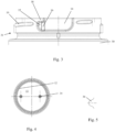
- the insertion direction 2 is parallel to the longitudinal axis 6 ( Fig. 8 ) of the outer cup 10.
- the removing direction 3 is opposite to the insertion direction 2 and is also parallel to the longitudinal axis 6 of the outer cup 10.
- the outer cup 10 is formed of glass and the inner cup 20 is formed of plastic, more preferably of polypropylene. Therefore, the outer cup 10 is rigid and the inner cup 20 is elastically deformable.
- the outer cup 10 is depicted having a body 30 with an outer wall 17, and having a neck 31 extending from the body 30 in the removing direction 3.
- the outer wall 17 also continues outside the neck 31, since the body 30 and the neck 31 are integrally formed.
- the neck 31 has a smaller outer diameter than the body 30.
- a cap (not shown), which is screwed to the external thread 19 (fourth protrusion) provided at the neck 31, does not protrude outside the outer wall 17 in the radial direction 4 ( Fig. 6 ) of the outer cup 10.
- the engaging portion of the outer cup 10 is formed.
- the recess 14 which is recessed with respect to the outer wall 17 inwards in the radial direction 4, is formed in the neck 31. This can be best seen in Figs. 7 and 9 .
- the recess 14 is connected with the axial front end 13 of the inner cup 10. That means that there is no land or any other protrusion or at least no protrusion being as high in the radial direction 4 as the outer wall 17 is, between the recess 14 and the axial front end 13.
- the engaging portion of the inner cup 20 can be inserted into the engaging portion of the outer cup 10 in the insertion direction 2 for coupling the cups 10, 20.
- the axial front end 13 of the outer cup 10 defines the first opening 12 of the outer cup 10 through which the inner cup 20 is insertable into and removable from the outer cup 10.
- the indentation 15 is formed in the neck 31.
- the indentation 15 is for accommodating the tab 23 ( Fig. 2 ) of the inner cup 20 in the engaged state of the outer and inner cups 10, 20.
- the indentation 15 is separated from the axial front end 13 by the land 18.
- the land 18 prevents the engaging portion of the inner cup 20 from sliding out in the removing direction 3 once the inner cup 20 and the outer cup 10 are engaged.
- the outer cup 10 has bumps 34 protruding upwards, i.e., in the removing direction 3 from the bottom of the first receptacle 11.
- the bumps 34 prevent a plane contact of the bottom of the first receptacle 11 and the bottom of the inner cup 20. If the consumables, fluids from outside (contaminations), or humidity were present between the bottom of the first receptacle 11 and the bottom of the inner cup 20, this might result in a situation that the bottom of the inner cup 20 is sucked to the bottom of the first receptacle 11, and the user could not easily remove the inner cup 20 from the outer cup 10.
- the bumps 34 contribute to an easy detachability of the inner cup 20 from the outer cup 10.
- the inner cup 20 has a circular flange 21 that protrudes from the outer wall 26 of the inner cup 20 into the radial direction 4.
- the flange supports the tongue 22 and also serves as a stop that abuts the axial front end 13 when the outer cup 20 is fully inserted into the inner cup 10.
- the tongue 22 protrudes in the insertion direction 2 from the flange 21 and has a length and a width which are large enough to make the tongue 22 a suitable gripping portion for the user.
- the tab 23 protrudes from the circumferential side of the tongue 22 in the circumferential direction 5 ( Fig. 6 ) of the inner cup 20 (or the container 1).
- the tab 23 is separated from the flange 21 in the insertion or removing direction 2, 3 by a gap 24.
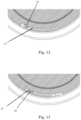
- the tab 23 is easily elastically deformable in the radial direction 4 when the second protrusion 27 ( Figs. 12 and 13 ) travels over the first protrusion 16 during engagement of the cups 10, 20.
- the second protrusion 27 protrudes inwards in the radial direction 4 from the radially inner side of the tab 23 ( Figs. 12 and 13 ).
- the inner cup 20 further has a second receptacle 29 for accommodating/storing consumables, preferably cosmetics or medical products. Further, the inner cup 20 has a second opening 28, which is defined by the flange 21. Through the second opening 28, the consumables are inserted into and taken out from the second receptacle 29.
- the second opening 28 is preferably covered by a thin plastic film that is connected to the flange 21, for example, by adhesive or by welding. Once the plastic film is (partially) removed, it cannot be simply reconnected to the flange 21 by the user. Therefore, the cap (not shown) is attachable to the outer cup 10 by means of the external thread 19, to protect the consumables from degradation.
- the inner cup 20 further has a plurality of ribs 25 (third protrusions).
- the ribs 25 are arranged at the outer wall 26 of the inner cup 20 such that they protrude outwards in the radial direction 4 and become larger in the radial direction 4 towards the removing direction 3.
- the ribs 25 have a substantially triangular shape. Further, the ribs 25 support the flange 21. Thus, they contribute to the mechanical strength of the flange 21 acting as an abutment portion during insertion of the inner cup 20 into the outer cup 10.
- the inner cup 20 has, at the region in which the ribs 25 are provided and at the largest extension of the ribs 25 in the radial direction 4, a larger outer diameter than the opening/inner diameter of the first opening 12. Since the ribs 25 are elastically deformable, they can be pressed through the first opening 12 in the insertion direction 2 and into the first receptacle 11 ( Figs. 4 and 8 ) of the outer cup 10 until the lower side (the side facing the insertion direction 2) of the flange 21 abuts the axial front end 13. By elastic deformation of the ribs 25, the outer and the inner cups 10, 20 are in a pre-engaged state by frictional connection.
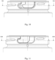
- the user can rotate the inner cup 20 by holding the tongues 22 in the clockwise direction, i.e., in the circumferential direction 5, to reach the (fully) engaged state shown in Figs. 11 and 13 .
- the second protrusion 27 approaches the first protrusion 16, abuts the first protrusion 16 on the side of the recess 14, moves outwards in the radial direction 4 by elastic deformation (of at least the second protrusion 27 and/or the tab 23, and/or the tongue 22 and/or the flange 21, and/or the outer wall 26), and travels beyond the first protrusion 16 to the side of the indentation 15 while gradually returning to the non-deformed state or a substantially non-deformed state as shown in Fig. 13 .
- a gap between the outer wall 26 of the inner cup 20 and the inner wall of the receptacle 11 of the outer cup 10 ( Fig. 8 , where the inner cup 20 depicted by dashed lines is shown inserted into the outer cup 10) provides, preferably in connection with a gap provided by the bumps 34, an air cushion between the cups 10, 20 which serves as a thermal insulation for the consumables.
Landscapes
- Engineering & Computer Science (AREA)
- Mechanical Engineering (AREA)
- Packages (AREA)
- Details Of Rigid Or Semi-Rigid Containers (AREA)
Priority Applications (3)
| Application Number | Priority Date | Filing Date | Title |
|---|---|---|---|
| EP23305076.4A EP4403489A1 (de) | 2023-01-23 | 2023-01-23 | Modularer behälter für kosmetika |
| US18/613,478 US20240300720A1 (en) | 2023-01-23 | 2024-03-22 | Modular container for cosmetics |
| CN202410333484.5A CN118373058A (zh) | 2023-01-23 | 2024-03-22 | 化妆品用模块化容器 |
Applications Claiming Priority (1)
| Application Number | Priority Date | Filing Date | Title |
|---|---|---|---|
| EP23305076.4A EP4403489A1 (de) | 2023-01-23 | 2023-01-23 | Modularer behälter für kosmetika |
Publications (1)
| Publication Number | Publication Date |
|---|---|
| EP4403489A1 true EP4403489A1 (de) | 2024-07-24 |
Family
ID=85328889
Family Applications (1)
| Application Number | Title | Priority Date | Filing Date |
|---|---|---|---|
| EP23305076.4A Pending EP4403489A1 (de) | 2023-01-23 | 2023-01-23 | Modularer behälter für kosmetika |
Country Status (3)
| Country | Link |
|---|---|
| US (1) | US20240300720A1 (de) |
| EP (1) | EP4403489A1 (de) |
| CN (1) | CN118373058A (de) |
Citations (4)
| Publication number | Priority date | Publication date | Assignee | Title |
|---|---|---|---|---|
| KR102164827B1 (ko) * | 2020-02-10 | 2020-10-13 | (주)아모레퍼시픽 | 리필 용기, 용기 본체 및 이를 포함하는 화장품 용기 |
| KR20210050865A (ko) * | 2019-10-29 | 2021-05-10 | (주)아모레퍼시픽 | 리필용기의 체결 구조가 개선된 화장품 용기 |
| US20220211161A1 (en) * | 2019-09-25 | 2022-07-07 | Pochet Du Courval | Container with internal glass receptacle and method for assembling the container by using a spacing and locking insert |
| WO2023139336A1 (fr) * | 2022-01-24 | 2023-07-27 | Medicos Izernore | Recipient de conditionnement d'un produit cosmetique, et recharge associee |
Family Cites Families (7)
| Publication number | Priority date | Publication date | Assignee | Title |
|---|---|---|---|---|
| US3156279A (en) * | 1960-08-29 | 1964-11-10 | Rexall Drug Chemical | Double-wall jar |
| BRPI0503738A (pt) * | 2005-08-23 | 2007-04-27 | Natura Cosmeticos Sa | sistema de trava e frasco compreendendo sistema de trava |
| KR20180115802A (ko) * | 2016-03-16 | 2018-10-23 | 에이치씨티 그룹 홀딩스 리미티드 | 자성 뚜껑 및 조립체 |
| KR102635507B1 (ko) * | 2019-09-09 | 2024-02-08 | (주)아모레퍼시픽 | 화장품 용기 |
| FR3124931B1 (fr) * | 2021-07-09 | 2026-02-13 | Albea Services | Pot distributeur de produit cosmétique avec godet rechargeable |
| KR20230168408A (ko) * | 2022-06-07 | 2023-12-14 | 주식회사 정민 | 리필형 화장품 용기 |
| KR20240017468A (ko) * | 2022-08-01 | 2024-02-08 | (주)아모레퍼시픽 | 리필용 화장품 용기 |
-
2023
- 2023-01-23 EP EP23305076.4A patent/EP4403489A1/de active Pending
-
2024
- 2024-03-22 CN CN202410333484.5A patent/CN118373058A/zh active Pending
- 2024-03-22 US US18/613,478 patent/US20240300720A1/en active Pending
Patent Citations (4)
| Publication number | Priority date | Publication date | Assignee | Title |
|---|---|---|---|---|
| US20220211161A1 (en) * | 2019-09-25 | 2022-07-07 | Pochet Du Courval | Container with internal glass receptacle and method for assembling the container by using a spacing and locking insert |
| KR20210050865A (ko) * | 2019-10-29 | 2021-05-10 | (주)아모레퍼시픽 | 리필용기의 체결 구조가 개선된 화장품 용기 |
| KR102164827B1 (ko) * | 2020-02-10 | 2020-10-13 | (주)아모레퍼시픽 | 리필 용기, 용기 본체 및 이를 포함하는 화장품 용기 |
| WO2023139336A1 (fr) * | 2022-01-24 | 2023-07-27 | Medicos Izernore | Recipient de conditionnement d'un produit cosmetique, et recharge associee |
Also Published As
| Publication number | Publication date |
|---|---|
| CN118373058A (zh) | 2024-07-23 |
| US20240300720A1 (en) | 2024-09-12 |
Similar Documents
| Publication | Publication Date | Title |
|---|---|---|
| US10398841B2 (en) | Adapter for a syringe | |
| JP4444122B2 (ja) | 一団の注射器本体物を保持するプレート | |
| JP5951768B2 (ja) | シリンジ収納容器 | |
| JP5192806B2 (ja) | 注射器又はカートリッジ、クロージング・キャップ、及び混合器を含む分配アセンブリ | |
| US5968021A (en) | Magazine and removable needle unit | |
| US5482095A (en) | Case for a dosing accessory adapted to be fixed on a bottle | |
| CN101631508B (zh) | 显微镜罩镜片盖系统及其组装方法 | |
| JP3420249B2 (ja) | 挿入手段を備えたコンタクトレンズ容器装置 | |
| US5765715A (en) | Drinking cup and cup holder | |
| JP2019503717A (ja) | コップ | |
| JP2011519681A (ja) | 遠位側端部の拡大されたカートリッジを有する薬剤送達器材 | |
| US20240101324A1 (en) | Container and Cap Assembly | |
| JP2002002767A (ja) | 飲料缶用キャップおよびストロー | |
| JP2005517596A (ja) | コンテナの蓋並びに蓋とボウルとの組合せ | |
| AU760880B2 (en) | Positive engagement-disengagement catheter sleeve | |
| CN114727698A (zh) | 具有集成夹头的包装 | |
| US20240300720A1 (en) | Modular container for cosmetics | |
| JP2009077943A (ja) | 注射器ホルダ及び注射器装置 | |
| WO2011122351A1 (ja) | シリンジセット | |
| WO2008075368A1 (en) | Ampoule breaker | |
| US20200071063A1 (en) | Roller case | |
| KR20040019948A (ko) | 플레이트 수납용 컨테이너 | |
| WO2005014428A1 (en) | Container assembly for blending contents kept separately by removing cap | |
| US7561349B2 (en) | Telescope and lens cap | |
| JP2012179241A (ja) | シリンジ |
Legal Events
| Date | Code | Title | Description |
|---|---|---|---|
| PUAI | Public reference made under article 153(3) epc to a published international application that has entered the european phase |
Free format text: ORIGINAL CODE: 0009012 |
|
| STAA | Information on the status of an ep patent application or granted ep patent |
Free format text: STATUS: REQUEST FOR EXAMINATION WAS MADE |
|
| 17P | Request for examination filed |
Effective date: 20230123 |
|
| AK | Designated contracting states |
Kind code of ref document: A1 Designated state(s): AL AT BE BG CH CY CZ DE DK EE ES FI FR GB GR HR HU IE IS IT LI LT LU LV MC ME MK MT NL NO PL PT RO RS SE SI SK SM TR |
|
| GRAP | Despatch of communication of intention to grant a patent |
Free format text: ORIGINAL CODE: EPIDOSNIGR1 |
|
| STAA | Information on the status of an ep patent application or granted ep patent |
Free format text: STATUS: GRANT OF PATENT IS INTENDED |
|
| INTG | Intention to grant announced |
Effective date: 20250305 |
|
| TPAC | Observations filed by third parties |
Free format text: ORIGINAL CODE: EPIDOSNTIPA |
|
| GRAJ | Information related to disapproval of communication of intention to grant by the applicant or resumption of examination proceedings by the epo deleted |
Free format text: ORIGINAL CODE: EPIDOSDIGR1 |
|
| STAA | Information on the status of an ep patent application or granted ep patent |
Free format text: STATUS: EXAMINATION IS IN PROGRESS |
|
| 17Q | First examination report despatched |
Effective date: 20250520 |
|
| INTC | Intention to grant announced (deleted) |