EP4403267A1 - Elektrostatische sprühvorrichtung - Google Patents
Elektrostatische sprühvorrichtung Download PDFInfo
- Publication number
- EP4403267A1 EP4403267A1 EP22869733.0A EP22869733A EP4403267A1 EP 4403267 A1 EP4403267 A1 EP 4403267A1 EP 22869733 A EP22869733 A EP 22869733A EP 4403267 A1 EP4403267 A1 EP 4403267A1
- Authority
- EP
- European Patent Office
- Prior art keywords
- spray nozzle
- charging section
- spraying device
- electrostatic spraying
- charging
- Prior art date
- Legal status (The legal status is an assumption and is not a legal conclusion. Google has not performed a legal analysis and makes no representation as to the accuracy of the status listed.)
- Pending
Links
Images


Classifications
-
- B—PERFORMING OPERATIONS; TRANSPORTING
- B05—SPRAYING OR ATOMISING IN GENERAL; APPLYING FLUENT MATERIALS TO SURFACES, IN GENERAL
- B05B—SPRAYING APPARATUS; ATOMISING APPARATUS; NOZZLES
- B05B5/00—Electrostatic spraying apparatus; Spraying apparatus with means for charging the spray electrically; Apparatus for spraying liquids or other fluent materials by other electric means
- B05B5/025—Discharge apparatus, e.g. electrostatic spray guns
- B05B5/053—Arrangements for supplying power, e.g. charging power
- B05B5/0533—Electrodes specially adapted therefor; Arrangements of electrodes
-
- A—HUMAN NECESSITIES
- A01—AGRICULTURE; FORESTRY; ANIMAL HUSBANDRY; HUNTING; TRAPPING; FISHING
- A01M—CATCHING, TRAPPING OR SCARING OF ANIMALS; APPARATUS FOR THE DESTRUCTION OF NOXIOUS ANIMALS OR NOXIOUS PLANTS
- A01M7/00—Special adaptations or arrangements of liquid-spraying apparatus for purposes covered by this subclass
- A01M7/005—Special arrangements or adaptations of the spraying or distributing parts, e.g. adaptations or mounting of the spray booms, mounting of the nozzles, protection shields
-
- B—PERFORMING OPERATIONS; TRANSPORTING
- B05—SPRAYING OR ATOMISING IN GENERAL; APPLYING FLUENT MATERIALS TO SURFACES, IN GENERAL
- B05B—SPRAYING APPARATUS; ATOMISING APPARATUS; NOZZLES
- B05B5/00—Electrostatic spraying apparatus; Spraying apparatus with means for charging the spray electrically; Apparatus for spraying liquids or other fluent materials by other electric means
- B05B5/025—Discharge apparatus, e.g. electrostatic spray guns
- B05B5/043—Discharge apparatus, e.g. electrostatic spray guns using induction-charging
-
- B—PERFORMING OPERATIONS; TRANSPORTING
- B05—SPRAYING OR ATOMISING IN GENERAL; APPLYING FLUENT MATERIALS TO SURFACES, IN GENERAL
- B05B—SPRAYING APPARATUS; ATOMISING APPARATUS; NOZZLES
- B05B5/00—Electrostatic spraying apparatus; Spraying apparatus with means for charging the spray electrically; Apparatus for spraying liquids or other fluent materials by other electric means
- B05B5/08—Plant for applying liquids or other fluent materials to objects
Definitions
- the present disclosure relates to an electrostatic spraying device.
- an electrostatic spraying device which includes a spray nozzle that sprays the chemical solution and a charging section that charges the chemical solution sprayed from the spray nozzle.
- the chemical solution sprayed from the spray nozzle is charged with a polarity opposite to that of a voltage applied to an electrode.
- the charged chemical solution spreads toward the field, and evenly adheres to the crops planted in the field due to the electrostatic effect.
- the electrostatic spraying device described in Patent Document 1 is a boom sprayer, and a plurality of spray nozzles are arranged in parallel in the longitudinal direction of a support rod (boom).
- a plurality of mounted portions are arranged in parallel along the longitudinal direction of the support rod.
- the charging section is a cable and is spanned between the plurality of mounted portions. Two charging sections or the outgoing path and the incoming path of one charging section are separated from each other with a spray area from the spray nozzle interposed therebetween.
- the charging section functions as an electrode.
- Patent Document 1 Japanese Patent Laid-Open Publication No. 2015-174035
- An object of the present disclosure is to provide an electrostatic spraying device capable of sufficiently charging a sprayed liquid.
- an electrostatic spraying device comprising: a spray nozzle which sprays a liquid; and a charging section which charges the liquid sprayed from the spray nozzle, wherein the spray nozzle is provided with a distal end movable around a base end, and wherein the charging section has a shape along a movement path of the distal end.
- the direction of the spray nozzle can be changed by moving the distal end of the spray nozzle around the base end thereof.
- the charging section has a shape along the movement path of the distal end of the spray nozzle, it is possible to maintain a constant separation distance between the charging section and the spray area from the spray nozzle even when the distal end of the spray nozzle moves to change the direction of the spray nozzle. Therefore, the sprayed liquid can be sufficiently charged.
- the electrostatic spraying device wherein the spray nozzle is provided with the distal end swingable around the base end, wherein the charging section is a strip plate extending in an arc shape, wherein the two charging sections are arranged to face each other with an appropriate separation distance in a thickness direction, and wherein a spray area from the spray nozzle is disposed between the two charging sections.
- the movement path of the distal end of the spray nozzle has an arc shape.
- the charging section is a band plate extending in an arc shape, the charging section has a shape along the movement path of the distal end.
- the sprayed liquid can be evenly charged.
- the electrostatic spraying device further comprising: a rod; a first support member that is attached to the rod and supports a power supply line supplying power to the charging section; and a second support member that is attached to the first support member and supports the charging section, wherein the second support member constitutes a part of a power supply path from the power supply line to the charging section.
- the first support member is attached to the rodshaped support body
- the second support member is attached to the first support member
- the second support member supports the charging section. Since the second support member constitutes a part of the power supply path, power is supplied from the power supply line to the charging section through the second support member.
- the first support member serves as a member that supports the power supply line and a member that connects the second support member to the support body and the second support member serves as a member that supports the charging section and a member that supplies power to the charging section. Therefore, the number of parts can be reduced.
- the electrostatic spraying device wherein the charging section is made of conductive resin.
- the charging section is made of conductive resin
- the charging section is lighter than, for example, the charging section made of metal.
- the charging section made of conductive resin has a higher electrical resistance than, for example, the charging section made of metal, the current flowing through the charging section is weakened. Therefore, the shock caused by electric shock generated when a human touches the charging section is suppressed.
- the conductive resin is suitable for forming a member with a complicated shape, it is easy to obtain a charging section having a shape that follows the movement path of the distal end of the spray nozzle.
- the sprayed liquid can be sufficiently charged.
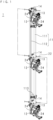
- FIG. 1 is a perspective view of an electrostatic spraying device according to the embodiment.
- Reference Numeral 1 denotes an electrostatic spraying device and the electrostatic spraying device 1 includes a support rod 11 and a plurality of spray nozzles 12.
- FIG. 2 is a schematic view of the electrostatic spraying device 1.
- the support rod 11 is supported by, for example, a hand-pushed or selfpropelled trolley 10, and moves together with the trolley 10.
- the support rod 11 includes a nozzle support 111 and a rod 112.
- the nozzle support 111 is a rod having an annular cross section.
- the rod 112 has an L-shaped cross section (see FIG. 5 described below).
- the nozzle support 111 and the rod 112 are fixed to each other in parallel by appropriate fixing fittings 113.
- the spray nozzle 12 is provided in the nozzle support 111 of the support rod 11.
- the plurality of spray nozzles 12 are arranged at appropriate intervals in the longitudinal direction of the support rod 11.
- a chemical solution (herbicide, plant growth regulator, or the like) is supplied to the spray nozzle 12 through a liquid supply path provided inside the nozzle support 111.
- the spray nozzle 12 sprays the supplied chemical solution.
- the spray nozzle 12 is provided so that its distal end can swing around its base end (see FIG. 6 described below).
- the support rod 11 is held so as to extend vertically, for example.
- the trolley 10 moves across the field so that the support rod 11 passes along the sides of the crops.
- the distal end of the spray nozzle 12 is directed toward the crop.
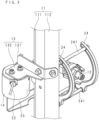
- FIG. 3 is a perspective view in the vicinity of the spray nozzle 12.
- FIG. 4 is a front view in the vicinity of the spray nozzle 12.
- FIG. 5 is a plan view in the vicinity of the spray nozzle 12.
- the electrostatic spraying device 1 includes each of a plurality of support fittings 13 and a housing 14 (first support member).
- the support fitting 13 is provided on the rod 112 of the support rod 11 at an appropriate separation distance from the spray nozzle 12.
- the plurality of support fittings 13 are arranged at appropriate intervals in the longitudinal direction of the support rod 11.
- the configuration of the support fitting 13 is not limited, but the support fitting 13 integrally includes at least a first portion 131 attached to the support rod 11 and a second portion 132 attached to the housing 14.
- the housing 14 has an insulating property and is made of, for example, synthetic resin.
- the housing 14 is attached to the rod 112 of the support rod 11 through the support fitting 13. As shown in FIGS. 1 and 2 , the plurality of housings 14 are arranged in the longitudinal direction of the support rod 11.
- the electrostatic spraying device 1 includes a high-voltage power supply 21 and a power supply line 22.
- the high-voltage power supply 21 includes, for example, a battery that outputs a DC voltage, a booster circuit that boosts the output of the battery, and is mounted on the trolley 10.
- the negative output terminal of the high-voltage power supply 21 is grounded via a ground wire (not shown).
- the positive output terminal of the high-voltage power supply 21 is connected to the power supply line 22.
- the electrostatic spraying device 1 includes the same number of support members 23 (second support members) as the number of housings 14.
- the support member 23 has conductivity, and is made of, for example, metal.
- the support member 23 is attached to the housing 14.
- the configuration of the support member 23 is not limited, but the support member 23 of this embodiment integrally includes a first portion 231, a second portion 232, and a third portion 233 in the form of a plate.
- the first portion 231 is attached to the housing 14.
- the second portion 232 supports a charging section 24 described below.
- the third portion 233 connects the first portion 231 and the second portion 232.
- the power supply line 22 is spanned between the plurality of housings 14.
- the power supply line 22 is drawn into each housing 14 and is electrically connected to the support member 23 through a power supply path (not shown) accommodated in the housing 14.
- the support fitting 13, the housing 14, and the support member 23 are sufficiently separated from the spray nozzle 12. Therefore, there is no risk that these will disturb the spraying of the chemical solution from the spray nozzle 12, and there is no risk that the chemical solution that adheres to these will flow into the spray nozzle 12.
- FIG. 6 is a schematic view illustrating a relationship between the swinging of the spray nozzle 12 and the shape of the charging section 24.
- FIG. 6 corresponds to a cross-sectional view taken along a line VI-VI of FIG. 5 .
- the spray nozzle 12 is supported by a support pipe 121.
- the support pipe 121 extends in a direction orthogonal to the longitudinal direction of the support rod 11 and is fixed to the nozzle support 111. If the longitudinal direction of the support rod 11 is vertical, the longitudinal direction of the support pipe 121 is also vertical. One end of the support pipe 121 in the longitudinal direction is connected to a liquid supply path of the support rod 11.
- the base end of the spray nozzle 12 is connected to the other end of the support pipe 121 in the longitudinal direction.
- the spray nozzle 12 is supported by the support pipe 121 so that the spray nozzle 12 is swingable around the support pipe 121 in a virtual plane perpendicular to the support pipe 121.
- the spray nozzle 12 swings when the operator manually applies external force to the spray nozzle 12.
- the operator adjusts the direction of the spray nozzle 12 within a predetermined range (for example, ⁇ 60° with respect to the state in which the spray nozzle 12 is oriented horizontally) depending on the positional relationship between the spray nozzle 12 and the crops planted in the field.
- a predetermined range for example, ⁇ 60° with respect to the state in which the spray nozzle 12 is oriented horizontally
- the spray nozzle 12 swung approximately 60° from the horizontally oriented state is represented by a two-dot chain line.
- the electrostatic spraying device 1 includes two charging sections 24 for each spray nozzle 12.
- the charging section 24 is a strip plate extending in an arc shape (see FIGS. 4 and 6 ).
- the charging section 24 is made of conductive resin and is not covered with an insulator.
- Two charging sections 24 are arranged to face each other with an appropriate separation distance in the thickness direction.
- Two charging sections 24 are integrated by being connected through a plurality of connecting rods 241.
- the connecting rod 241 extends in the facing direction of two charging sections 24.
- the connecting rods 241 are, for example, straight rods having an annular cross section, and the plurality of connecting rods 241 are separated from each other with an appropriate separation distance in the longitudinal direction of the charging section 24 (see FIG. 6 ).
- the connecting rod 241 has conductivity, and is made of, for example, metal.
- One of two charging sections 24 is attached to the second portion 232 of the support member 23 so that a spray area (not shown) from the spray nozzle 12 is disposed between two charging sections 24(the spray area is an area where the liquid is sprayed from the spray nozzle 12).
- the spray area has, for example, a cone shape or a fan shape with the apex of the spray nozzle 12 as the apex.
- Power is supplied from the power supply line 22 to the charging section 24 and the charging section 24 functions as a positive electrode for charging a chemical solution. Power is supplied from the power supply line 22 to the charging section 24 through the support member 23 and the power supply path accommodated in the housing 14. As a result, a current flows through the surface of the charging section 24.
- the charging section 24 is separated from the spray nozzle 12 by a distance in which the spraying of the chemical solution from the spray nozzle 12 is not disturbed or the chemical solution adhering to the charging section 24 does not flow into the spray nozzle 12. Further, the charging section 24 is disposed in the vicinity of the spray area of the spray nozzle 12 so that the chemical solution sprayed from the spray nozzle 12 can be sufficiently inductively charged.
- the charging section 24 extends along the movement path of the distal end of the spray nozzle 12 and can maintain a constant separation distance between the spray area from the spray nozzle 12 and the charging section 24 even when the distal end of the spray nozzle 12 moves to change the direction of the spray nozzle 12. Therefore, the sprayed chemical solution can be sufficiently charged. Further, since the spray area from the spray nozzle 12 is disposed between two charging sections 24, the sprayed chemical solution can be evenly charged.
- a part where the liquid film is formed in the spray area is disposed between two charging sections 24.
- the width of the charging section 24 which is a band plate, the sprayed chemical solution can be sufficiently charged even if the position of the liquid film is slightly shifted in the spray direction.
- the chemical solution sprayed from the spray nozzle 12 spreads toward the crops. Since the charging section 24 is a positive electrode, a negative charge is given to the chemical solution sprayed from the spray nozzle 12. When a negative charge exists near a crop, the crop becomes polarized, for example, so that the upper and lower surfaces of the leaf are positive and the inside of the leaf is negative. For this reason, the negatively charged chemical solution is attracted to the crop and evenly adheres to both the upper and lower surfaces of the leaves.
- the housing 14 serves as a member that supports the power supply line and a member that connects the support member 23 to the support rod 11 and the support member 23 serves as a member that supports the charging section 24 and a member that supplies power to the charging section 24. Therefore, the number of parts can be reduced.
- the charging section 24 is not limited to being made of conductive resin, and may be made of, for example, metal. However, the charging section 24 made of conductive resin is lighter than the charging section 24 made of metal. Further, since the charging section 24 made of conductive resin has a higher electrical resistance than the charging section 24 made of metal, the current flowing through the charging section 24 is weakened. Therefore, the shock caused by electric shock generated when a human touches the charging section 24 is suppressed.
- the movement paths of the distal ends of the spray nozzles are the same even if the sizes or shapes of the plurality of spray nozzles 12 are different from each other, it is possible to use the charging section 24 in common.
- the charging section 24 is not limited to a band plate extending in an arc shape, but may be a rod body extending in an arc shape.
- the charging section 24 may have a shape along the movement path of the distal end of the spray nozzle 12.
- the charging section 24 may have an annular shape coaxial with the movement path of the distal end of the spray nozzle 12.
- the spray nozzle 12 may be configured to be driven by, for example, a motor and automatically swing.
- the support rod 11 may not include the rod 112.
- the housing 14 is attached to the nozzle support 111.
Landscapes
- Life Sciences & Earth Sciences (AREA)
- Engineering & Computer Science (AREA)
- Insects & Arthropods (AREA)
- Pest Control & Pesticides (AREA)
- Wood Science & Technology (AREA)
- Zoology (AREA)
- Environmental Sciences (AREA)
- Electrostatic Spraying Apparatus (AREA)
- Catching Or Destruction (AREA)
Applications Claiming Priority (2)
| Application Number | Priority Date | Filing Date | Title |
|---|---|---|---|
| JP2021151238A JP7546289B2 (ja) | 2021-09-16 | 2021-09-16 | 静電噴霧装置 |
| PCT/JP2022/030710 WO2023042586A1 (ja) | 2021-09-16 | 2022-08-12 | 静電噴霧装置 |
Publications (2)
| Publication Number | Publication Date |
|---|---|
| EP4403267A1 true EP4403267A1 (de) | 2024-07-24 |
| EP4403267A4 EP4403267A4 (de) | 2025-10-01 |
Family
ID=85602121
Family Applications (1)
| Application Number | Title | Priority Date | Filing Date |
|---|---|---|---|
| EP22869733.0A Pending EP4403267A4 (de) | 2021-09-16 | 2022-08-12 | Elektrostatische sprühvorrichtung |
Country Status (4)
| Country | Link |
|---|---|
| US (1) | US20240382985A1 (de) |
| EP (1) | EP4403267A4 (de) |
| JP (1) | JP7546289B2 (de) |
| WO (1) | WO2023042586A1 (de) |
Family Cites Families (10)
| Publication number | Priority date | Publication date | Assignee | Title |
|---|---|---|---|---|
| US5044564A (en) * | 1989-11-21 | 1991-09-03 | Sickles James E | Electrostatic spray gun |
| US6708908B2 (en) * | 2001-06-29 | 2004-03-23 | Behr Systems, Inc. | Paint atomizer bell with ionization ring |
| US20070194157A1 (en) * | 2002-08-06 | 2007-08-23 | Clean Earth Technologies, Llc | Method and apparatus for high transfer efficiency electrostatic spray |
| US7913938B2 (en) * | 2004-11-12 | 2011-03-29 | Mystic Tan, Inc. | Electrostatic spray nozzle with adjustable fluid tip and interchangeable components |
| JP4816292B2 (ja) * | 2006-07-07 | 2011-11-16 | 株式会社やまびこ | 静電付与式散布機 |
| JP5453683B2 (ja) * | 2008-09-11 | 2014-03-26 | 株式会社やまびこ | 静電噴霧用電極部材 |
| JP5434071B2 (ja) * | 2008-12-25 | 2014-03-05 | 井関農機株式会社 | 自走型除草機 |
| JP5581610B2 (ja) * | 2009-06-02 | 2014-09-03 | ダイキン工業株式会社 | 静電噴霧装置 |
| JP5891456B2 (ja) * | 2012-01-11 | 2016-03-23 | パナソニックIpマネジメント株式会社 | 静電霧化装置 |
| JP6316625B2 (ja) * | 2014-03-14 | 2018-04-25 | 有光工業株式会社 | 静電噴霧装置 |
-
2021
- 2021-09-16 JP JP2021151238A patent/JP7546289B2/ja active Active
-
2022
- 2022-08-12 WO PCT/JP2022/030710 patent/WO2023042586A1/ja not_active Ceased
- 2022-08-12 EP EP22869733.0A patent/EP4403267A4/de active Pending
- 2022-08-12 US US18/691,709 patent/US20240382985A1/en active Pending
Also Published As
| Publication number | Publication date |
|---|---|
| WO2023042586A1 (ja) | 2023-03-23 |
| US20240382985A1 (en) | 2024-11-21 |
| EP4403267A4 (de) | 2025-10-01 |
| JP2023043546A (ja) | 2023-03-29 |
| JP7546289B2 (ja) | 2024-09-06 |
Similar Documents
| Publication | Publication Date | Title |
|---|---|---|
| EP0186353B1 (de) | Sprühgerät | |
| CS239924B2 (en) | Holder of vessel for electrostatically sprayed liquid | |
| US4805069A (en) | Powder charging apparatus and electrostatic powder painting apparatus | |
| KR102428094B1 (ko) | 초음파 헤드를 갖는 코팅 시스템 | |
| CA2790304C (en) | Aerial spraying apparatus | |
| CA1223573A (en) | Aerial spraying apparatus | |
| US11292017B2 (en) | Insulated electrostatically assisted spraying extender | |
| US9498785B2 (en) | Electrostatic spraying device | |
| EP4403267A1 (de) | Elektrostatische sprühvorrichtung | |
| US4157162A (en) | Electrostatic spraying apparatus | |
| EP4084243A1 (de) | Elektrostatischer abscheider | |
| JPS6139869A (ja) | 高電圧制御 | |
| JP6316625B2 (ja) | 静電噴霧装置 | |
| WO2016067310A4 (en) | Manually controlled variable coverage high range electrostatic sprayer | |
| JP2018069157A (ja) | 静電噴霧装置、飛行体、及び静電噴霧方法 | |
| EP4403265A1 (de) | Elektrostatische sprühvorrichtung | |
| US5042723A (en) | Electrostatic spraying apparatus | |
| EP4403266A1 (de) | Elektrostatische sprühvorrichtung | |
| EP2747892A1 (de) | Sprühverfahren und sprühkopf mit einer lavaldüse und einer ringförmigen induktionselektrode | |
| JP2008119557A (ja) | 外部電極を備えた外部帯電式静電塗装ガン | |
| CN207056838U (zh) | 一种航空静电喷雾系统 | |
| AU625892B2 (en) | Electrostatic spraying apparatus | |
| JP3686892B2 (ja) | 粉体静電塗装用ガン | |
| JP2547804B2 (ja) | 静電噴霧装置 | |
| GB2123713A (en) | Aerial spraying |
Legal Events
| Date | Code | Title | Description |
|---|---|---|---|
| STAA | Information on the status of an ep patent application or granted ep patent |
Free format text: STATUS: THE INTERNATIONAL PUBLICATION HAS BEEN MADE |
|
| PUAI | Public reference made under article 153(3) epc to a published international application that has entered the european phase |
Free format text: ORIGINAL CODE: 0009012 |
|
| STAA | Information on the status of an ep patent application or granted ep patent |
Free format text: STATUS: REQUEST FOR EXAMINATION WAS MADE |
|
| 17P | Request for examination filed |
Effective date: 20240416 |
|
| AK | Designated contracting states |
Kind code of ref document: A1 Designated state(s): AL AT BE BG CH CY CZ DE DK EE ES FI FR GB GR HR HU IE IS IT LI LT LU LV MC MK MT NL NO PL PT RO RS SE SI SK SM TR |
|
| DAV | Request for validation of the european patent (deleted) | ||
| DAX | Request for extension of the european patent (deleted) | ||
| REG | Reference to a national code |
Ref country code: DE Ref legal event code: R079 Free format text: PREVIOUS MAIN CLASS: B05B0005080000 Ipc: A01M0007000000 |
|
| A4 | Supplementary search report drawn up and despatched |
Effective date: 20250828 |
|
| RIC1 | Information provided on ipc code assigned before grant |
Ipc: A01M 7/00 20060101AFI20250825BHEP Ipc: B05B 5/025 20060101ALI20250825BHEP Ipc: B05B 5/053 20060101ALI20250825BHEP Ipc: B05B 5/08 20060101ALI20250825BHEP Ipc: B05B 5/043 20060101ALI20250825BHEP |