EP4403247A1 - Co2 recovery system, and co2 recovery method - Google Patents
Co2 recovery system, and co2 recovery method Download PDFInfo
- Publication number
- EP4403247A1 EP4403247A1 EP22883585.6A EP22883585A EP4403247A1 EP 4403247 A1 EP4403247 A1 EP 4403247A1 EP 22883585 A EP22883585 A EP 22883585A EP 4403247 A1 EP4403247 A1 EP 4403247A1
- Authority
- EP
- European Patent Office
- Prior art keywords
- exhaust gas
- cooling water
- cooling device
- flow rate
- recovery system
- Prior art date
- Legal status (The legal status is an assumption and is not a legal conclusion. Google has not performed a legal analysis and makes no representation as to the accuracy of the status listed.)
- Pending
Links
Images






Classifications
-
- B—PERFORMING OPERATIONS; TRANSPORTING
- B01—PHYSICAL OR CHEMICAL PROCESSES OR APPARATUS IN GENERAL
- B01D—SEPARATION
- B01D53/00—Separation of gases or vapours; Recovering vapours of volatile solvents from gases; Chemical or biological purification of waste gases, e.g. engine exhaust gases, smoke, fumes, flue gases, aerosols
- B01D53/14—Separation of gases or vapours; Recovering vapours of volatile solvents from gases; Chemical or biological purification of waste gases, e.g. engine exhaust gases, smoke, fumes, flue gases, aerosols by absorption
-
- B—PERFORMING OPERATIONS; TRANSPORTING
- B01—PHYSICAL OR CHEMICAL PROCESSES OR APPARATUS IN GENERAL
- B01D—SEPARATION
- B01D51/00—Auxiliary pretreatment of gases or vapours to be cleaned
- B01D51/10—Conditioning the gas to be cleaned
-
- B—PERFORMING OPERATIONS; TRANSPORTING
- B01—PHYSICAL OR CHEMICAL PROCESSES OR APPARATUS IN GENERAL
- B01D—SEPARATION
- B01D53/00—Separation of gases or vapours; Recovering vapours of volatile solvents from gases; Chemical or biological purification of waste gases, e.g. engine exhaust gases, smoke, fumes, flue gases, aerosols
- B01D53/14—Separation of gases or vapours; Recovering vapours of volatile solvents from gases; Chemical or biological purification of waste gases, e.g. engine exhaust gases, smoke, fumes, flue gases, aerosols by absorption
- B01D53/1412—Controlling the absorption process
-
- B—PERFORMING OPERATIONS; TRANSPORTING
- B01—PHYSICAL OR CHEMICAL PROCESSES OR APPARATUS IN GENERAL
- B01D—SEPARATION
- B01D53/00—Separation of gases or vapours; Recovering vapours of volatile solvents from gases; Chemical or biological purification of waste gases, e.g. engine exhaust gases, smoke, fumes, flue gases, aerosols
- B01D53/14—Separation of gases or vapours; Recovering vapours of volatile solvents from gases; Chemical or biological purification of waste gases, e.g. engine exhaust gases, smoke, fumes, flue gases, aerosols by absorption
- B01D53/1418—Recovery of products
-
- B—PERFORMING OPERATIONS; TRANSPORTING
- B01—PHYSICAL OR CHEMICAL PROCESSES OR APPARATUS IN GENERAL
- B01D—SEPARATION
- B01D53/00—Separation of gases or vapours; Recovering vapours of volatile solvents from gases; Chemical or biological purification of waste gases, e.g. engine exhaust gases, smoke, fumes, flue gases, aerosols
- B01D53/14—Separation of gases or vapours; Recovering vapours of volatile solvents from gases; Chemical or biological purification of waste gases, e.g. engine exhaust gases, smoke, fumes, flue gases, aerosols by absorption
- B01D53/1431—Pretreatment by other processes
-
- B—PERFORMING OPERATIONS; TRANSPORTING
- B01—PHYSICAL OR CHEMICAL PROCESSES OR APPARATUS IN GENERAL
- B01D—SEPARATION
- B01D53/00—Separation of gases or vapours; Recovering vapours of volatile solvents from gases; Chemical or biological purification of waste gases, e.g. engine exhaust gases, smoke, fumes, flue gases, aerosols
- B01D53/14—Separation of gases or vapours; Recovering vapours of volatile solvents from gases; Chemical or biological purification of waste gases, e.g. engine exhaust gases, smoke, fumes, flue gases, aerosols by absorption
- B01D53/1456—Removing acid components
- B01D53/1475—Removing carbon dioxide
-
- B—PERFORMING OPERATIONS; TRANSPORTING
- B01—PHYSICAL OR CHEMICAL PROCESSES OR APPARATUS IN GENERAL
- B01D—SEPARATION
- B01D53/00—Separation of gases or vapours; Recovering vapours of volatile solvents from gases; Chemical or biological purification of waste gases, e.g. engine exhaust gases, smoke, fumes, flue gases, aerosols
- B01D53/14—Separation of gases or vapours; Recovering vapours of volatile solvents from gases; Chemical or biological purification of waste gases, e.g. engine exhaust gases, smoke, fumes, flue gases, aerosols by absorption
- B01D53/18—Absorbing units; Liquid distributors therefor
-
- B—PERFORMING OPERATIONS; TRANSPORTING
- B01—PHYSICAL OR CHEMICAL PROCESSES OR APPARATUS IN GENERAL
- B01D—SEPARATION
- B01D53/00—Separation of gases or vapours; Recovering vapours of volatile solvents from gases; Chemical or biological purification of waste gases, e.g. engine exhaust gases, smoke, fumes, flue gases, aerosols
- B01D53/26—Drying gases or vapours
- B01D53/265—Drying gases or vapours by refrigeration (condensation)
-
- B—PERFORMING OPERATIONS; TRANSPORTING
- B01—PHYSICAL OR CHEMICAL PROCESSES OR APPARATUS IN GENERAL
- B01D—SEPARATION
- B01D53/00—Separation of gases or vapours; Recovering vapours of volatile solvents from gases; Chemical or biological purification of waste gases, e.g. engine exhaust gases, smoke, fumes, flue gases, aerosols
- B01D53/34—Chemical or biological purification of waste gases
- B01D53/46—Removing components of defined structure
- B01D53/62—Carbon oxides
-
- C—CHEMISTRY; METALLURGY
- C01—INORGANIC CHEMISTRY
- C01B—NON-METALLIC ELEMENTS; COMPOUNDS THEREOF; METALLOIDS OR COMPOUNDS THEREOF NOT COVERED BY SUBCLASS C01C
- C01B32/00—Carbon; Compounds thereof
- C01B32/50—Carbon dioxide
-
- B—PERFORMING OPERATIONS; TRANSPORTING
- B01—PHYSICAL OR CHEMICAL PROCESSES OR APPARATUS IN GENERAL
- B01D—SEPARATION
- B01D2251/00—Reactants
- B01D2251/30—Alkali metal compounds
- B01D2251/304—Alkali metal compounds of sodium
-
- B—PERFORMING OPERATIONS; TRANSPORTING
- B01—PHYSICAL OR CHEMICAL PROCESSES OR APPARATUS IN GENERAL
- B01D—SEPARATION
- B01D2251/00—Reactants
- B01D2251/60—Inorganic bases or salts
- B01D2251/604—Hydroxides
-
- B—PERFORMING OPERATIONS; TRANSPORTING
- B01—PHYSICAL OR CHEMICAL PROCESSES OR APPARATUS IN GENERAL
- B01D—SEPARATION
- B01D2252/00—Absorbents, i.e. solvents and liquid materials for gas absorption
- B01D2252/20—Organic absorbents
- B01D2252/204—Amines
- B01D2252/20478—Alkanolamines
-
- B—PERFORMING OPERATIONS; TRANSPORTING
- B01—PHYSICAL OR CHEMICAL PROCESSES OR APPARATUS IN GENERAL
- B01D—SEPARATION
- B01D2256/00—Main component in the product gas stream after treatment
- B01D2256/22—Carbon dioxide
-
- B—PERFORMING OPERATIONS; TRANSPORTING
- B01—PHYSICAL OR CHEMICAL PROCESSES OR APPARATUS IN GENERAL
- B01D—SEPARATION
- B01D2257/00—Components to be removed
- B01D2257/20—Halogens or halogen compounds
- B01D2257/204—Inorganic halogen compounds
- B01D2257/2045—Hydrochloric acid
-
- B—PERFORMING OPERATIONS; TRANSPORTING
- B01—PHYSICAL OR CHEMICAL PROCESSES OR APPARATUS IN GENERAL
- B01D—SEPARATION
- B01D2257/00—Components to be removed
- B01D2257/30—Sulfur compounds
- B01D2257/302—Sulfur oxides
-
- B—PERFORMING OPERATIONS; TRANSPORTING
- B01—PHYSICAL OR CHEMICAL PROCESSES OR APPARATUS IN GENERAL
- B01D—SEPARATION
- B01D2257/00—Components to be removed
- B01D2257/50—Carbon oxides
- B01D2257/504—Carbon dioxide
-
- B—PERFORMING OPERATIONS; TRANSPORTING
- B01—PHYSICAL OR CHEMICAL PROCESSES OR APPARATUS IN GENERAL
- B01D—SEPARATION
- B01D2258/00—Sources of waste gases
- B01D2258/02—Other waste gases
- B01D2258/0283—Flue gases
-
- B—PERFORMING OPERATIONS; TRANSPORTING
- B01—PHYSICAL OR CHEMICAL PROCESSES OR APPARATUS IN GENERAL
- B01D—SEPARATION
- B01D53/00—Separation of gases or vapours; Recovering vapours of volatile solvents from gases; Chemical or biological purification of waste gases, e.g. engine exhaust gases, smoke, fumes, flue gases, aerosols
- B01D53/34—Chemical or biological purification of waste gases
- B01D53/74—General processes for purification of waste gases; Apparatus or devices specially adapted therefor
- B01D53/77—Liquid phase processes
- B01D53/78—Liquid phase processes with gas-liquid contact
Definitions
- the present disclosure relates to a CO 2 recovery system and a CO 2 recovery method.
- PTL 1 describes a method of removing and recovering CO 2 in an exhaust gas discharged from a combustion facility or the like by bringing the CO 2 into contact with a CO 2 absorption liquid using, for example, an amine aqueous solution.
- wastewater generated from moisture in the exhaust gas or the like is discharged to the outside of the system, and a wastewater treatment is performed during the discharge. Therefore, it is required to appropriately treat the wastewater.
- the present disclosure has been made to solve the above-described problem, and an object of the present disclosure is to provide a CO 2 recovery system and a CO 2 recovery method capable of appropriately treating wastewater.
- a CO 2 recovery system including: a combustion facility; a dust collector that removes a solid component from an exhaust gas containing CO 2 , the exhaust gas being discharged from the combustion facility and introduced into the dust collector; an exhaust gas cooling device that brings the exhaust gas, which is introduced into the exhaust gas cooling device, into contact with cooling water to cool the exhaust gas; a CO 2 absorption tower that brings the exhaust gas, which is cooled by the exhaust gas cooling device and introduced into the CO 2 absorption tower, into contact with a CO 2 absorption liquid to remove the CO 2 from the exhaust gas; and a cooling water introduction line that is connected to the exhaust gas cooling device and a supply location, which is a location upstream of the dust collector in a flow of the exhaust gas, and allows at least a portion of the cooling water inside the exhaust gas cooling device to be introduced into the supply location.
- a CO 2 recovery method including: a step of generating an exhaust gas containing CO 2 by combusting in a combustion facility; a step of removing a solid component from the exhaust gas discharged from the combustion facility, through a dust collector; a step of bringing the exhaust gas into contact with cooling water to cool the exhaust gas, through an exhaust gas cooling device; a step of bringing the exhaust gas cooled by the exhaust gas cooling device into contact with a CO 2 absorption liquid to remove the CO 2 from the exhaust gas; and a step of introducing at least a portion of the cooling water inside the exhaust gas cooling device to a supply location, which is a location upstream of the dust collector in a flow of the exhaust gas.
- wastewater can be appropriately treated.
- the present invention is not limited by the embodiment, and in a case where there are a plurality of the embodiments, the present invention also includes configurations in which the respective embodiments are combined with each other.
- Fig. 1 is a schematic block diagram of a CO 2 recovery system according to a first embodiment.
- a CO 2 recovery system 100 according to the first embodiment includes a combustion facility 2, an exhaust gas treatment facility 3, a chimney 8, an adjustment unit V1, and a CO 2 recovery apparatus 10.
- the combustion facility 2 is a facility that receives introduced fuel F and air A and combusts the fuel F.
- An exhaust gas G0 generated by combustion is discharged from the combustion facility 2.
- the exhaust gas G0 is a gas containing CO 2 .
- the fuel F may be any fuel, and examples thereof include coal, natural gas, waste, biogas, blast furnace gas, and coke oven gas.
- the combustion facility 2 may be any facility as long as the fuel F is combusted.
- the exhaust gas treatment facility 3 is a facility that treats the exhaust gas G0 discharged from the combustion facility 2.
- the exhaust gas treatment facility 3 is connected to the combustion facility 2 via a discharge line 2A.
- the exhaust gas G0 discharged from the combustion facility 2 is introduced into the exhaust gas treatment facility 3 through the discharge line 2A and is treated in the exhaust gas treatment facility 3.
- the exhaust gas treatment facility 3 may be a facility that performs any treatment on the exhaust gas G0, but preferably includes a dust collector 6.
- the dust collector 6 is a device that recovers a solid component (dust) contained in the exhaust gas G0.
- the dust collector 6 may recover the solid component (dust) by filtering the exhaust gas G0 with a filter. Since the recovery of the CO 2 from the exhaust gas G0 is performed by the CO 2 recovery apparatus 10, the exhaust gas treatment facility 3 in the present embodiment may perform a process other than recovering the CO 2 from the exhaust gas G0.
- the exhaust gas treatment facility 3 includes a temperature-reducing tower 4 that cools the exhaust gas G0 and the dust collector 6.
- the temperature-reducing tower 4 is provided upstream of the dust collector 6 in a flow of the exhaust gas G0 and, in other words, is provided between the combustion facility 2 and the dust collector 6.
- the temperature-reducing tower 4 is connected to the discharge line 2A, and the exhaust gas G0 discharged from the combustion facility 2 is introduced from the discharge line 2A.
- the temperature-reducing tower 4 cools the exhaust gas G0 by supplying (spraying, in the present embodiment) cooling water to the exhaust gas G0.
- the temperature-reducing tower 4 and the dust collector 6 are connected to each other via a discharge line 4A.
- the exhaust gas G0 cooled by the temperature-reducing tower 4 is introduced into the dust collector 6 through the discharge line 4A, and at least a portion of the solid component is recovered by the dust collector 6.
- the configuration of the exhaust gas treatment facility 3 is not limited to the above description and may be any configuration, and for example, only the dust collector 6 may be provided, or a device other than the temperature-reducing tower 4 and the dust collector 6 may be provided.
- the chimney 8 is a tower that discharges an exhaust gas G1 treated by the exhaust gas treatment facility 3.
- the chimney 8 is connected to the exhaust gas treatment facility 3 via a discharge line 6A. More specifically, in the present embodiment, the dust collector 6 and the chimney 8 are connected via the discharge line 6A.
- the exhaust gas G1 from which the solid component has been removed by the dust collector 6 is introduced into the chimney 8 through the discharge line 6A and is discharged from the chimney 8.
- the CO 2 recovery system 100 may be provided with a power generation facility that generates power by using the exhaust gas as a power source.
- the power generation facility may be provided, for example, between the combustion facility 2 and the exhaust gas treatment facility 3.
- the CO 2 recovery apparatus 10 is an apparatus that recovers CO 2 from the exhaust gas G0 discharged from the combustion facility 2. More specifically, the CO 2 recovery apparatus 10 brings the exhaust gas G0, which is discharged from the combustion facility 2 and introduced into the CO 2 recovery apparatus 10, into contact with a CO 2 absorption liquid S1 to remove the CO 2 from the exhaust gas G0.
- the CO 2 recovery apparatus 10 is connected to the combustion facility 2 via an exhaust gas introduction line 6B.
- the exhaust gas introduction line 6B is branched from the discharge line 6A and is connected to the discharge line 6A and the CO 2 recovery apparatus 10. That is, in the present embodiment, it can be said that the CO 2 recovery apparatus 10 is connected to the exhaust gas treatment facility 3 via the exhaust gas introduction line 6B. Therefore, the exhaust gas G1 that has been treated by the exhaust gas treatment facility 3 is introduced into the CO 2 recovery apparatus 10.
- the exhaust gas introduction line 6B is provided with the adjustment unit V1 that adjusts a flow rate of the exhaust gas G1 to be introduced into the CO 2 recovery apparatus 10.
- the adjustment unit V1 is an openable/closable valve in the present embodiment, and introduces the exhaust gas G1 into the CO 2 recovery apparatus 10 in an opened state and stops the introduction of the exhaust gas G1 into the CO 2 recovery apparatus 10 in a closed state.
- the adjustment unit V1 can adjust the flow rate of the exhaust gas G1 to be introduced into the CO 2 recovery apparatus 10 by adjusting the opening degree thereof.
- the adjustment unit V1 may be controlled by a control unit 40, which will be described below.
- the adjustment unit V1 is not limited to the valve and may be any mechanism capable of adjusting the flow rate of the exhaust gas G1.
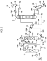
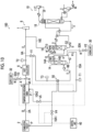
- Fig. 2 is a schematic diagram of the CO 2 recovery apparatus according to the first embodiment. As shown in Fig. 2 , the CO 2 recovery apparatus 10 includes an exhaust gas cooling device 14, a CO 2 absorption tower 16, and a regeneration tower 18.
- the exhaust gas cooling device 14 is a device that cools the exhaust gas G1 by using cooling water W, and may be called an exhaust gas cooling tower.
- the exhaust gas cooling device 14 is connected to the exhaust gas introduction line 6B, and the exhaust gas G0 (the exhaust gas G1 treated by the exhaust gas treatment facility 3, in the present embodiment) discharged from the combustion facility 2 is introduced from the exhaust gas introduction line 6B.
- a blower B0 is disposed on the exhaust gas introduction line 6B, and the exhaust gas G1 boosted by the blower B0 is introduced into the exhaust gas cooling device 14.
- a cooled exhaust gas introduction line 14A and a cooling line 14B are connected to the exhaust gas cooling device 14.
- the cooling line 14B is a pipe for circulating the cooling water W into the exhaust gas cooling device 14.
- the cooling line 14B is provided with a pump P1 and a cooler CW1.
- the cooling water W is circulated by driving the pump P1.
- the cooling water W is cooled by the cooler CW1, and then is supplied into the exhaust gas cooling device 14 to come into contact with the exhaust gas G1 introduced into the exhaust gas cooling device 14, thereby cooling the exhaust gas G1 to a predetermined temperature.
- the cooling water W that has cooled the exhaust gas G1 inside the exhaust gas cooling device 14 is returned from the exhaust gas cooling device 14 to the cooling line 14B.
- the CO 2 absorption tower 16 is a facility that brings the exhaust gas into contact with the CO 2 absorption liquid S1 to remove the CO 2 from the exhaust gas.
- the CO 2 absorption tower 16 is provided at a downstream stage of the exhaust gas cooling device 14 in a flow direction of the exhaust gas G.
- the CO 2 absorption tower 16 is connected to the exhaust gas cooling device 14 via the cooled exhaust gas introduction line 14A.
- An exhaust gas G2, which is the exhaust gas G1 cooled by the exhaust gas cooling device 14, is introduced into the CO 2 absorption tower 16 through the cooled exhaust gas introduction line 14A. That is, in the present embodiment, the CO 2 absorption tower 16 removes the CO 2 from the exhaust gas G2 cooled by the exhaust gas cooling device 14.
- the CO 2 absorption tower 16 includes a CO 2 recovery section 16A and a washing section 16B.
- the CO 2 in the exhaust gas G2 is removed by the CO 2 absorption liquid S1.
- the CO 2 absorption liquid S1 is supplied, so that the exhaust gas G2 passing through the CO 2 recovery section 16A comes into countercurrent contact with the CO 2 absorption liquid S1.
- the CO 2 in the exhaust gas G2 is absorbed by the CO 2 absorption liquid S1 through a chemical reaction.
- the rinse liquid W2 supplied from a nozzle comes into gas-liquid contact with the decarbonated gas G3, and the CO 2 absorption liquid S1 (a component of the CO 2 absorption liquid S1) entrained in the decarbonated gas G3 is recovered.
- a rinse water circulation line 16D is connected, and the rinse liquid W2 is circulated by a pump P2 disposed on the rinse water circulation line 16D.
- the rinse liquid W2 is cooled by a cooler CW2 disposed on the rinse water circulation line 16D and is supplied into the washing section 16B to wash the passing decarbonated gas G3 while cooling the decarbonated gas G3 to a predetermined temperature.
- the mist-like CO 2 absorption liquid S1 (the component of the CO 2 absorption liquid S1) entrained in the decarbonated gas G3 is washed with the rinse liquid W2 in the washing section 16B, so that the discharge of the CO 2 absorption liquid entrained in the decarbonated gas G3 is prevented, thereby reducing the emission.
- the temperature at which the decarbonated gas G3 is cooled may be substantially the same as the introduction temperature at which the exhaust gas G2 is introduced into the CO 2 absorption tower 16, and this maintains the water balance within the system.
- the cooling temperature may be adjusted such that the moisture amount in the decarbonated gas G3 to be discharged from the top of the CO 2 absorption tower 16 is also 10 wt%.
- the CO 2 absorption tower 16 is connected to the discharge line 6A via a decarbonated gas introduction line 16E.
- the decarbonated gas G3 is discharged from the chimney 8 through the decarbonated gas introduction line 16E and the discharge line 6A.
- the CO 2 absorption liquid S1 is not particularly limited, and examples thereof include amine compounds such as alkanolamines or hindered amines having an alcoholic hydroxyl group.
- alkanolamines include monoethanolamine, diethanolamine, triethanolamine, methyldiethanolamine, diisopropanolamine, and diglycolamine, and monoethanolamine (MEA) is generally preferable.
- examples of the hindered amines having an alcoholic hydroxyl group include 2-amino-2-methyl-1-propanol (AMP), 2-(ethylamino)-ethanol (EAE), 2-(methylamino)-ethanol (MAE), and 2-(diethylamino)-ethanol (DEAE).
- a rich solution S2 which is the CO 2 absorption liquid S1 that has absorbed the CO 2 in the exhaust gas G2, is stored in a bottom portion of the CO 2 absorption tower 16.
- a rich solution introduction line 16C through which the rich solution S2 is discharged from the bottom portion of the CO 2 absorption tower 16 and the rich solution S2 is introduced into a regeneration tower 18 side, and a lean solution introduction line 18A through which the CO 2 absorption liquid S1 (lean solution) is discharged from a bottom portion of the regeneration tower 18 and is introduced into a CO 2 absorption tower 16 side intersect each other and are connected to the CO 2 absorption tower 16 and the regeneration tower 18.
- a heat exchanger CW3 is disposed at an intersection of the rich solution introduction line 16C and the lean solution introduction line 18A.
- the rich solution S2 is heated by the CO 2 absorption liquid S1 (lean solution) regenerated by the regeneration tower 18 and is supplied to the regeneration tower 18.
- a pump P3 that boosts the CO 2 absorption liquid S1 (lean solution) and a cooler CW4 that cools the CO 2 absorption liquid S1 (lean solution) using cooling water are disposed between the heat exchanger CW3 and the CO 2 absorption tower 16, and the CO 2 absorption liquid S1 (lean solution) regenerated by the regeneration tower 18 is supplied into the CO 2 absorption tower 16 after being boosted and cooled through the lean solution introduction line 18A.
- the regeneration tower 18 absorbs CO 2 from the rich solution S2 that has absorbed the CO 2 in the exhaust gas G2 in the CO 2 absorption tower 16, and regenerates the CO 2 absorption liquid S1.
- a reboiler CW5 disposed on a reboiler line 18C is provided on a bottom portion side of the regeneration tower 18. In the reboiler CW5, when a portion of the CO 2 absorption liquid S1 (lean solution) is circulated through the reboiler line 18C, a portion of the CO 2 absorption liquid S1 (lean solution) is indirectly heated by saturated steam B, and the steam is introduced into the inside of the regeneration tower 18.
- the reboiler CW5 is provided with a saturated steam introduction line 18D for introducing the saturated steam B.
- a separation drum 26 is disposed on the saturated steam introduction line 18D and separates a condensed steam water WB.
- the rich solution S2 generated in the CO 2 absorption tower 16 is introduced into the regeneration tower 18 from the rich solution introduction line 16C.
- a boost pump P4 is disposed on the rich solution introduction line 16C, and the rich solution S2 is boosted by the boost pump P4, heated by the heat exchanger CW3 using the CO 2 absorption liquid S1 (lean solution) regenerated by the regeneration tower 18, and supplied to the regeneration tower 18.
- the rich solution S2 released from an upper portion side of a side surface to the inside of the regeneration tower 18 is subjected to an endothermic reaction by the steam supplied from the bottom portion side, and most of the CO 2 is desorbed and released.
- the CO 2 absorption liquid that has released a portion or most of the CO 2 in the regeneration tower 18 is referred to as a semi-lean solution.
- the semi-lean solution becomes the CO 2 absorption liquid S1 (lean solution) in which nearly all the CO 2 has been removed.
- a portion of the CO 2 absorption liquid S1 (lean solution) is heated by the reboiler CW5 using the saturated steam B, and the steam for CO 2 desorption is supplied to the inside of the regeneration tower 18.
- a gas discharge line 18B for discharging a CO 2 -entrained gas accompanying the steam released from the rich solution S2 and the semi-lean solution in the tower is connected to the top of the regeneration tower 18.
- the gas discharge line 18B is provided with a cooler CW6 that cools the CO 2 -entrained gas accompanying the steam, and a reflux water drum 28 that flashes the cooled CO 2 -entrained gas to perform gas-liquid separation.
- the reflux water separated and recirculated from the CO 2 -entrained gas accompanying the steam in the reflux water drum 28 is supplied to the upper portion of the regeneration tower 18 by a reflux water circulation pump P5 disposed on a reflux water line 18E.
- a separated gas discharge line 18F for discharging a CO 2 gas C which is the CO 2 -entrained gas from which the reflux water is separated, is connected to the top of the reflux water drum 28.
- the CO 2 gas C discharged through the separated gas discharge line 18F is, for example, compressed and recovered.
- the CO 2 gas C is sent to a use destination, and for example, may be used for the cultivation of plants in a plant factory, may be used for chemical synthesis or the like, may be injected into an oil field by using an enhanced oil recovery (EOR), or may be stored in an aquifer.
- EOR enhanced oil recovery
- the CO 2 recovery apparatus 10 has the above-described configuration.
- the exhaust gas cooling device 14 brings the cooling water W into contact with the exhaust gas G1 to cool the exhaust gas G1. Therefore, the moisture in the exhaust gas G1 is condensed into the condensed water and is entrained in the cooling water W, and this may lead to an increase in the flow rate of the cooling water W.
- at least a portion of the cooling water W is introduced into a supply location P, which is a location upstream of the dust collector 6 in the flow of the exhaust gas G0, so that it is possible to appropriately treat the excessive cooling water W as wastewater while suppressing an excessive increase in the flow rate of the cooling water W inside the exhaust gas cooling device 14.
- Fig. 3 is a schematic block diagram of the CO 2 recovery system according to the first embodiment.
- the CO 2 recovery system 100 includes a cooling water introduction line 10A, an adding unit 30, a supply unit 32, the control unit 40, and sensors T1 and T2.
- the cooling water introduction line 10A is a pipe for connecting the exhaust gas cooling device 14 and the supply location P to each other.
- the cooling water introduction line 10A is connected to the cooling line 14B and is connected to the exhaust gas cooling device 14 via the cooling line 14B.
- the cooling water introduction line 10A may be directly connected to the exhaust gas cooling device 14 without passing through the cooling line 14B.
- Cooling water W1 (wastewater), which is a portion of the cooling water W inside the exhaust gas cooling device 14, is introduced into the cooling water introduction line 10A and is introduced into the supply location P through the cooling water introduction line 10A.
- the supply location P to which the cooling water introduction line 10A is connected may be any location upstream of the dust collector 6 in the flow of the exhaust gas G0, and the supply location P may be one or multiple.
- the combustion facility 2 and the temperature-reducing tower 4 are the supply locations P. That is, in the example of the present embodiment, the cooling water introduction line 10A is connected to the combustion facility 2 and the temperature-reducing tower 4.
- the cooling water introduction line 10A is branched into cooling water introduction lines 10A1 and 10A2, the cooling water introduction line 10A1 is connected to the combustion facility 2, and the cooling water introduction line 10A2 is connected to the temperature-reducing tower 4.
- the exhaust gas cooling device 14 (cooling line 14B) and the combustion facility 2 are connected to each other via the cooling water introduction lines 10A and 10A1, and the cooling water W1 inside the exhaust gas cooling device 14 (cooling line 14B) is introduced into the combustion facility 2 through the cooling water introduction lines 10A and 10A1.
- the cooling water W1 introduced into the combustion facility 2 is evaporated by being heated in the combustion facility 2.
- the combustion temperature in the combustion facility 2 is adjusted by supplying the cooling water W1 to the combustion facility 2.
- a temperature sensor such as a thermocouple is installed inside the combustion facility, and the combustion gas temperature of a high-temperature portion in the combustion facility is set to 1400°C or lower, so that the amount of NOx generated can be suppressed.
- the connection location (that is, the supply location P) of the cooling water introduction line 10A1 in the combustion facility 2 may be at any position.
- the exhaust gas cooling device 14 (cooling line 14B) and the temperature-reducing tower 4 are connected to each other via the cooling water introduction lines 10A and 10A2, and the cooling water W1 inside the exhaust gas cooling device 14 (cooling line 14B) is introduced into the temperature-reducing tower 4 through the cooling water introduction lines 10A and 10A2.
- the cooling water W1 introduced into the temperature-reducing tower 4 is treated in the temperature-reducing tower 4. Specifically, the cooling water W introduced into the temperature-reducing tower 4 is sprayed toward the exhaust gas G0 in the temperature-reducing tower 4, thereby reducing the temperature of the exhaust gas G0.
- the cooling water W1 inside the exhaust gas cooling device 14 is supplied to both the combustion facility 2 and the temperature-reducing tower 4, but the present disclosure is not limited thereto, and the cooling water W1 may be supplied to any one of the combustion facility 2 and the temperature-reducing tower 4.
- the cooling water introduction line 10A may be configured to connect the exhaust gas cooling device 14 (cooling line 14B) and the combustion facility 2 without providing the cooling water introduction line 10A2.
- the cooling water introduction line 10A may be configured to connect the exhaust gas cooling device 14 (cooling line 14B) and the temperature-reducing tower 4 without providing the cooling water introduction line 10A1.
- the flow rate of the cooling water W increases by the amount of the condensed water of the exhaust gas G1. Since the cooling water W1 is a portion extracted from the cooling water W, it can be said that the cooling water W1 contains the condensed water of the exhaust gas G1.
- the cooling water introduction line 10A is not provided with a mechanism that performs water treatment on the cooling water W1, the cooling water W1 in a state of containing the condensed water of the exhaust gas G1 and not being subjected to water treatment may be supplied to the supply location P.
- the water treatment herein refers to, for example, processes such as removing or clarifying foreign matters in the cooling water W1.
- the flow rate of the cooling water W1 to be supplied to the supply location P (the combustion facility 2 and the temperature-reducing tower 4 in the example of the present embodiment) through the cooling water introduction line 10A may be any flow rate, but it is preferable that an amount corresponding to the flow rate of the cooling water W increased inside the exhaust gas cooling device 14 (an amount within a predetermined range with respect to the increased flow rate) is set as the flow rate of the cooling water W1. Further, in the present embodiment, the increased flow rate of the cooling water W inside the exhaust gas cooling device 14 is set as the flow rate of the cooling water W1.
- the flow rate of the cooling water W1 corresponds to the flow rate of the condensed water of the exhaust gas G1 entrained in the cooling water W (that is, the flow rate of the condensed water generated in the exhaust gas cooling device 14). Therefore, in the present embodiment, the supply location P is supplied with the cooling water W1 corresponding to the increased flow rate inside the exhaust gas cooling device 14.
- the flow rate of the cooling water W1 may be adjusted by any method to have the flow rate of the cooling water W increased inside the exhaust gas cooling device 14.
- the opening degree of an opening-closing valve or the like may be adjusted to maintain a constant amount of the cooling water W to be returned from the cooling line 14B into the exhaust gas cooling device 14. In this case, the cooling water W corresponding to the increased flow rate inside the exhaust gas cooling device 14 is led out to the cooling water introduction line 10A as the cooling water W1 without being returned to the exhaust gas cooling device 14.
- the adding unit 30 is a device that adds a pH adjuster M1 to the cooling water W.
- the pH adjuster M1 is a chemical agent for adjusting the pH of the cooling water W and is, in the present embodiment, an alkaline agent for raising the pH of the cooling water W.
- Examples of the pH adjuster M1 include a sodium hydroxide aqueous solution.
- the adding unit 30 is connected to the cooling line 14B via an introduction line 30A.
- the pH adjuster M1 from the adding unit 30 is added to the cooling water W flowing through the cooling line 14B through the introduction line 30A. Consequently, the pH of the cooling water W is adjusted, and the pH of the cooling water W1 which is a portion of the cooling water W is also adjusted.
- the adding unit 30 is not limited to being connected to the cooling line 14B, and may be directly connected to, for example, the exhaust gas cooling device 14 or may be connected to the cooling water introduction line 10A. In a case where the adding unit 30 is connected to the cooling water introduction line 10A, the pH adjuster M1 is added to the cooling water W1.
- the introduction line 30A may be provided with an adjustment unit V2 that adjusts the addition of the pH adjuster M1 to the cooling water W.
- the adjustment unit V2 is an openable/closable valve in the present embodiment, and adds the pH adjuster M1 to the cooling water W in an opened state and stops the addition of the pH adjuster M1 to the cooling water W in a closed state.
- the adjustment unit V2 can adjust the addition amount of the pH adjuster M1 by adjusting the opening degree thereof.
- the adjustment unit V2 may be controlled by the control unit 40, which will be described below.
- the adjustment unit V2 is not limited to the valve and may be any mechanism capable of adjusting the addition amount of the pH adjuster M1.
- the supply unit 32 is a device that supplies an acidic gas remover M2 to the exhaust gas G0.
- the acidic gas remover M2 is a chemical agent for removing at least a portion of an acidic gas contained in the exhaust gas G0.
- the same agent as the pH adjuster M1 may be used as the acidic gas remover M2.
- the supply unit 32 is connected to the discharge line 4A via an introduction line 32A.
- the acidic gas remover M2 from the supply unit 32 is supplied to the exhaust gas G0 flowing through the discharge line 4A through the introduction line 32A. Consequently, at least a portion of the acidic gas contained in the exhaust gas G0 is removed.
- the supply unit 32 is not limited to being connected to the discharge line 4A (that is, between the temperature-reducing tower 4 and the dust collector 6), and may be connected to any location downstream of the combustion facility 2 in the flow of the exhaust gas G0, more specifically, to any location between the combustion facility 2 and the chimney 8.
- the supply unit 32 may supply a carrier gas (for example, air) for supplying the acidic gas remover M2, together with the acidic gas remover M2.
- the introduction line 32A may be provided with an adjustment unit V3 that adjusts the supply of the acidic gas remover M2 to the exhaust gas G0.
- the adjustment unit V3 is an openable/closable valve in the present embodiment, and supplies the acidic gas remover M2 to the exhaust gas G0 in an opened state and stops the supply of the acidic gas remover M2 to the exhaust gas G0 in a closed state.
- the adjustment unit V3 can adjust the supply amount of the acidic gas remover M2 by adjusting the opening degree thereof.
- the adjustment unit V3 may be controlled by the control unit 40, which will be described below.
- the adjustment unit V3 is not limited to the valve and may be any mechanism capable of adjusting the supply amount of the acidic gas remover M2.
- the adjustment unit V3 is not an essential configuration and may not be included in the CO 2 recovery system 100.
- the control unit 40 may be, for example, a computer including an arithmetic circuit such as a central processing unit (CPU).
- the control unit 40 reads a program (software) from a storage unit (not shown) and executes control of each unit of the CO 2 recovery system 100, such as the control of the flow rate of the exhaust gas G1.
- the control unit 40 controls the adjustment unit V1 to control the flow rate of the exhaust gas G1 to be introduced into the CO 2 recovery apparatus 10 through the adjustment unit V1.
- the control unit 40 may adjust the flow rate of the exhaust gas G1 to be introduced into the CO 2 recovery apparatus 10, for example, according to the combustion state in the combustion facility 2.
- the combustion state herein indicates the degree of combustion in the combustion facility 2 and may be, for example, a combustion amount, a combustion temperature, or the like.
- the control unit 40 may increase the flow rate of the exhaust gas G1 to be introduced into the CO 2 recovery apparatus 10 as the combustion amount in the combustion facility 2 increases (for example, as the amount of heat generated per unit amount of the fuel F increases).
- the control unit 40 controls the adjustment unit V2 to control the addition amount of the pH adjuster M1 to the cooling water W through the adjustment unit V2.
- the control unit 40 controls the addition amount of the pH adjuster M1 such that the pH of the cooling water W and W1 falls within a predetermined range, based on at least one of the pH of the cooling water W1 and the flow rate of the cooling water W1.
- the cooling water introduction line 10A is provided with the sensor T1 that measures the pH of the cooling water W1 and the flow rate of the cooling water W1
- the control unit 40 controls the addition amount of the pH adjuster M1 such that the pH of the cooling water W falls within a predetermined range, based on the pH and the flow rate of the cooling water W1 measured by the sensor T1.
- the predetermined range herein may be any range, and the pH may be, for example, in a range of 5 or more and 8 or less.
- the sensor T1 is provided on the cooling water introduction line 10A, but a position where the sensor T1 is provided is not limited thereto, and the sensor T1 may be provided at any position where the flow rate of the cooling water W or the cooling water W1 can be measured.
- the control unit 40 is not limited to controlling the addition amount of the pH adjuster M1 based on the measurement result of the sensor T1 and may control the addition amount of the pH adjuster M1 by any method.
- the control unit 40 may set the addition amount of the pH adjuster M1 to be constant or may control the addition amount of the pH adjuster M1 based on the inflow rate of the exhaust gas G1 to the exhaust gas cooling device 14.
- the control unit 40 controls the adjustment unit V3 to control the supply amount of the acidic gas remover M2 to the exhaust gas G0 through the adjustment unit V3.
- the control unit 40 controls the supply amount of the acidic gas remover M2 such that the amount of impurities contained in the exhaust gas G1 falls within a predetermined range, based on the amount of impurities in the exhaust gas G1 downstream of a location to which the supply unit 32 is connected, in the flow direction of the exhaust gas G0.
- the sensor T2 that measures the amount of impurities contained in the exhaust gas G1 is provided downstream (here, downstream of the dust collector 6) of the location to which the supply unit 32 is connected, and the control unit 40 controls the supply amount of the acidic gas remover M2 such that the amount of impurities contained in the exhaust gas G1 falls within a predetermined range, based on the amount of impurities measured by the sensor T2.
- the impurities herein are, for example, HCl or SOx, and the predetermined range herein may be any range.
- the control unit 40 is not limited to controlling the supply amount of the acidic gas remover M2 based on the measurement result of the sensor T2 and may control the supply amount of the acidic gas remover M2 by any method.
- the control unit 40 may set the supply amount of the acidic gas remover M2 to be constant or may control the supply amount of the acidic gas remover M2 based on at least one of the pH of the cooling water W1 and the flow rate of the cooling water W1.
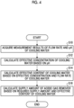
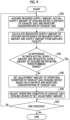
- Fig. 4 is a flowchart illustrating an example of a method for setting the supply amount of the acidic gas remover.
- an example of setting the supply amount of the acidic gas remover M2 based on the pH and the flow rate of the cooling water W1 will be described.
- the flow rate of the cooling water W1 indicates the flow rate of the cooling water W1 to be introduced into the temperature-reducing tower 4.
- the control unit 40 acquires the measurement results of the flow rate and the pH of the cooling water W1 by the sensor T1 (step S10).
- the control unit 40 calculates the effective concentration of the cooling water W1 based on the pH of the cooling water W1 measured by the sensor T1 (step S12).
- the effective concentration herein indicates a concentration (kg/L) of an effective component in the cooling water W1, which is capable of removing the acidic gas from the exhaust gas G0.
- the effective component capable of removing the acidic gas from the exhaust gas G0 may be, for example, an alkaline component.
- the control unit 40 may calculate the effective concentration of the cooling water W1 by any method, based on the pH of the cooling water W1. For example, a correspondence relationship between the pH and the effective concentration may be set in advance, and the control unit 40 may calculate the effective concentration of the cooling water W1 by substituting the measurement result of the pH of the cooling water W1 into the set correspondence relationship.
- the control unit 40 calculates the effective content of the cooling water W1 based on the effective concentration of the cooling water W1 and the measurement result of the flow rate of the cooling water W1 (step S14).
- the effective content indicates the amount of the effective component that is capable of removing the acidic gas from the exhaust gas G0 and that is contained in the cooling water W1 to be supplied to the supply location P (here, the temperature-reducing tower 4).
- the control unit 40 calculates the effective content by multiplying, for example, the effective concentration of the cooling water W1 and the flow rate of the cooling water W1.
- the control unit 40 calculates the supply amount of the acidic gas remover M2 based on a required supply amount of the acidic gas remover M2 and an effective flow rate of the cooling water W1 (step S16).
- the required supply amount of the acidic gas remover M2 indicates the amount of the acidic gas remover M2 required to remove the desired amount of the acidic gas from the exhaust gas G0 in a case where it is assumed that the cooling water W1 is not supplied to the exhaust gas G0.
- the control unit 40 may use a value obtained by subtracting the effective flow rate of the cooling water W1 from the required supply amount of the acidic gas remover M2 as the supply amount of the acidic gas remover M2.
- the control unit 40 controls the adjustment unit V3 such that the supply amount of the acidic gas remover M2 is the calculated supply amount.
- the control unit 40 may calculate the required supply amount, based on the amount of impurities in the exhaust gas G0 before the supply of the acidic gas remover M2 or the cooling water W1.
- the sensor T2 is provided upstream of the temperature-reducing tower 4 and the location to which the supply unit 32 is connected, and the control unit 40 acquires the amount of impurities in the exhaust gas G0 measured by the sensor T2.
- the method for acquiring the required supply amount is not limited thereto and may be any method.
- the required supply amount may be calculated based on the flow rate of the exhaust gas G0, or the required supply amount may be set as a constant value.
- the cooling water W1 inside the exhaust gas cooling device 14 is introduced into the supply location P such as the combustion facility 2 or the temperature-reducing tower 4. Therefore, it is possible to suppress an excessive increase in the flow rate of the cooling water W inside the exhaust gas cooling device 14.
- the cooling water W1 since the cooling water W1 is treated by the combustion facility 2, the temperature-reducing tower 4, or the like, the cooling water W1 can be appropriately treated. Further, for example, even if there is no dedicated facility for treating the cooling water W1, the cooling water W1 can be appropriately treated.
- the acidic gas can be removed from the exhaust gas G0 by the effective component (the component capable of removing the acidic gas from the exhaust gas G0) contained in the cooling water W1, so that the supply amount of the acidic gas remover M2 can also be reduced.
- the acidic gas remover M2 is supplied by the carrier gas, the amount of the carrier gas can be reduced by reducing the amount of the acidic gas remover M2, the CO 2 concentration in the exhaust gas G1 drawn into the CO 2 recovery apparatus 10 can be improved, and the efficiency of CO 2 recovery can be improved.
- the second embodiment is different from the first embodiment in that adjustment units V4 and V5 are provided to control the introduction amount of the cooling water W1.
- adjustment units V4 and V5 are provided to control the introduction amount of the cooling water W1.
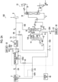
- Fig. 5A is a schematic block diagram of a CO 2 recovery system according to the second embodiment.
- the cooling water introduction line 10A is provided with the adjustment unit that adjusts the supply amount of the cooling water W1 to the supply location P.
- the cooling water introduction line 10A1 is provided with the adjustment unit V4.
- the adjustment unit V4 is an openable/closable valve in the present embodiment, and introduces the cooling water W1 into the combustion facility 2 in an opened state and stops the introduction of the cooling water W1 into the combustion facility 2 in a closed state.
- the adjustment unit V4 can adjust the flow rate of the cooling water W1 to be introduced into the combustion facility 2 by adjusting the opening degree thereof.
- the adjustment unit V4 may be controlled by the control unit 40.
- the control unit 40 controls the adjustment unit V4 to control the flow rate of the cooling water W1 to be introduced into the combustion facility 2 through the adjustment unit V4.
- the control unit 40 may adjust the flow rate of the cooling water W1, for example, according to the combustion state in the combustion facility 2.
- the control unit 40 may increase the flow rate of the cooling water W1 to be introduced into the combustion facility 2 as the combustion amount in the combustion facility 2 increases (for example, as the introduction amount of the fuel F increases).
- the control unit 40 may increase the flow rate of the cooling water W1 to be introduced into the combustion facility 2, for example, as the combustion temperature in the combustion facility 2 increases.
- control unit 40 may maintain the flow rate of the cooling water W1 at a predetermined value in a case where the combustion temperature of the combustion facility 2 is equal to or lower than a predetermined threshold value, and may increase the flow rate of the cooling water W1 to be introduced into the combustion facility 2 beyond the predetermined value in a case where the combustion temperature of the combustion facility 2 exceeds the threshold value.
- the adjustment unit V4 is not limited to the valve and may be any mechanism capable of adjusting the supply amount of the cooling water W1.
- the combustion state in the combustion facility 2 may be acquired by any method and may be acquired by a sensor that detects the combustion state, for example.
- the cooling water introduction line 10A2 is provided with the adjustment unit V5.
- the adjustment unit V5 is an openable/closable valve in the present embodiment, and introduces the cooling water W1 into the temperature-reducing tower 4 in an opened state and stops the introduction of the cooling water W1 into the temperature-reducing tower 4 in a closed state.
- the adjustment unit V5 can adjust the flow rate of the cooling water W1 to be introduced into the temperature-reducing tower 4 by adjusting the opening degree thereof.
- the adjustment unit V5 may be controlled by the control unit 40.
- the control unit 40 controls the adjustment unit V5 to control the flow rate of the cooling water W1 to be introduced into the temperature-reducing tower 4 through the adjustment unit V5.
- the control unit 40 may adjust the flow rate of the cooling water W1, for example, according to at least one of the flow rate and the temperature of the exhaust gas G0 to be introduced into the temperature-reducing tower 4.
- the control unit 40 may increase the flow rate of the cooling water W1 to be introduced into the temperature-reducing tower 4 as the amount of the exhaust gas G0 to be introduced into the temperature-reducing tower 4 increases.
- the control unit 40 may increase the flow rate of the cooling water W1 to be introduced into the temperature-reducing tower 4, for example, as the temperature of the exhaust gas G0 to be introduced into the temperature-reducing tower 4 increases.
- control unit 40 may maintain the flow rate of the cooling water W1 at a predetermined value in a case where the temperature of the exhaust gas G0 is equal to or lower than a predetermined threshold value, and may increase the flow rate of the cooling water W1 to be introduced into the temperature-reducing tower 4 beyond the predetermined value in a case where the temperature of the exhaust gas G0 exceeds the threshold value.
- the adjustment unit V5 is not limited to the valve and may be any mechanism capable of adjusting the supply amount of the cooling water W1.
- the flow rate or the temperature of the exhaust gas G0 may be acquired by any method and for example, may be acquired by a sensor that detects the flow rate or the temperature of the exhaust gas G0.
- the control unit 40 may prioritize the supply of the cooling water W1 to the combustion facility 2 over the supply of the cooling water W1 to the temperature-reducing tower 4. That is, for example, in a case where the flow rate of the cooling water W1 to be introduced into the cooling water introduction line 10A (that is, the flow rate of the cooling water W increased in the exhaust gas cooling device 14) is smaller than the total value of the requested flow rates of the cooling water W1 in the combustion facility 2 and the temperature-reducing tower 4, the control unit 40 may adjust the supply flow rates to the combustion facility 2 and the temperature-reducing tower 4 such that the supply flow rate to the combustion facility 2 is closer to the requested flow rate than the supply flow rate to the temperature-reducing tower 4 is.
- control unit 40 may adjust the supply flow rates to the combustion facility 2 and the temperature-reducing tower 4 such that a value obtained by subtracting the supply flow rate from the requested flow rate of the combustion facility 2 is smaller than a value obtained by subtracting the supply flow rate from the requested flow rate of the temperature-reducing tower 4.
- the cooling water W1 inside the exhaust gas cooling device 14 may be supplied to any one of the combustion facility 2 and the temperature-reducing tower 4, as in the first embodiment.
- the exhaust gas can be appropriately treated while the cooling water W1 can also be appropriately treated.
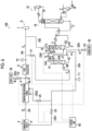
- Fig. 5B is a schematic block diagram of a CO 2 recovery system according to another example of the second embodiment.
- the cooling water introduction line 10A may be provided with a buffer tank BT that temporarily stores the cooling water W1 corresponding to the increased flow rate inside the exhaust gas cooling device 14.
- the buffer tank BT By providing the buffer tank BT, it is possible to more suitably suppress an increase in the cooling water W1 inside the exhaust gas cooling device 14.
- the cooling water W1 is introduced into the buffer tank BT from a cooling water introduction line 10AA, which is a portion upstream of the buffer tank BT on the cooling water introduction line 10A, and the cooling water W1 is then stored in the buffer tank BT.
- a cooling water introduction line 10AA which is a portion upstream of the buffer tank BT on the cooling water introduction line 10A
- a cooling water introduction line 10AB which is a portion downstream of the buffer tank BT on the cooling water introduction line 10A, is connected to a bottom portion of the buffer tank BT.
- the cooling water introduction line 10AB is provided with a pump P6 which is a mechanism that adjusts the flow rate in the buffer tank BT.
- the control unit 40 controls the pump P6 to lead out the cooling water W1 stored in the buffer tank BT to the cooling water introduction lines 10A1 and 10A2 via the cooling water introduction line 10AB. Consequently, the flow rate in the buffer tank BT is adjusted.
- the connection location of the cooling water introduction line 10AB is not limited to a bottom surface of the buffer tank BT and may be any location.
- the pump P6 is not an essential configuration, and any device other than the pump may be provided to adjust the flow rate in the buffer tank BT.
- the third embodiment is different from the second embodiment in that the flow rate of the cooling water W1 to be supplied to the cooling water introduction line 10A is controlled.
- description of the parts with a configuration common to the second embodiment will not be repeated.
- the third embodiment can also be applied to the first embodiment.
- Fig. 6 is a schematic block diagram of a CO 2 recovery system according to the third embodiment.
- the cooling water W1 corresponding to the increased flow rate of the cooling water W in the exhaust gas cooling device 14 is introduced into the cooling water introduction line 10A.
- the flow rate of the cooling water W1 to be introduced into the cooling water introduction line 10A is adjusted by adjusting the amount of increase in the cooling water W in the exhaust gas cooling device 14 according to the required flow rate of the cooling water W1 that should be introduced into the supply location P.
- the control unit 40 adjusts the temperature (hereinafter, referred to as an exhaust gas outlet temperature) of the exhaust gas G1 to be discharged from the exhaust gas cooling device 14 by controlling an operating condition of the exhaust gas cooling device 14 based on the required flow rate of the cooling water W1 to be introduced into the supply location P.
- an exhaust gas outlet temperature changes, the amount of decrease in the temperature of the exhaust gas G1 (a difference between the exhaust gas outlet temperature and the temperature of the exhaust gas at the inlet of the exhaust gas cooling device 14) in the exhaust gas cooling device 14 changes, so that the amount of the condensed water of the exhaust gas G1 changes, and the flow rate of the cooling water W1 to be introduced into the cooling water introduction line 10A also changes.
- the operating condition of the exhaust gas cooling device 14 for adjusting the exhaust gas outlet temperature may be at least one of the temperature of the cooling water W to be brought into contact with the exhaust gas G1 (the cooling water W to be returned to the exhaust gas cooling device 14) and the flow rate per unit time of the cooling water W to be brought into contact with the exhaust gas G1, and in the present embodiment, the operating condition is the temperature of the cooling water W to be brought into contact with the exhaust gas G1.
- the control unit 40 controls the temperature of the cooling water W by controlling, for example, the cooler CW1.
- control unit 40 controls the flow rate per unit time of the cooling water W to be returned to the exhaust gas cooling device 14 by adjusting the opening degree of a valve (not shown) that is provided on the cooling line 14B and that adjusts the flow rate of the cooling water W.
- the operating condition for adjusting the exhaust gas outlet temperature is not limited thereto and may be any parameter capable of changing the exhaust gas outlet temperature.
- the control unit 40 controls the operating condition of the exhaust gas cooling device 14 based on the actual supply amount of the cooling water W1 and the required flow rate of the cooling water.
- the actual supply amount of the cooling water W1 is the flow rate of the cooling water W1 to be actually introduced into the cooling water introduction line 10A
- the required supply amount of the cooling water is the flow rate of the cooling water that should be supplied to the supply location P (here, the combustion facility 2 or the temperature-reducing tower 4).
- the supply location P here, the combustion facility 2 or the temperature-reducing tower 4
- Fig. 7 is a flowchart illustrating a control flow of the operating condition according to the third embodiment.
- the control unit 40 acquires the required supply amount of the cooling water and the actual supply amount of the cooling water W1 (step S20).
- the control unit 40 may acquire the required supply amount by any method, or may calculate the required supply amount, for example, based on the combustion state of the combustion facility 2, the flow rate of the exhaust gas G0 to be introduced into the temperature-reducing tower 4, the temperature of the exhaust gas G0 to be introduced into the temperature-reducing tower 4, or the like.
- the required supply amount may be set in advance, and the control unit 40 may acquire information on the required supply amount set in advance.
- the control unit 40 may acquire the actual supply amount by any method. For example, the control unit 40 acquires information on the supply amount of the cooling water W1 measured by the sensor T1 as the actual supply amount.
- the control unit 40 calculates a requested supply amount of the cooling water W1 based on the required supply amount of the cooling water and the supply amount of the cooling water from another facility (step S22).
- the supply amount of the cooling water from another facility indicates the amount of the cooling water to be supplied to the supply location P from a facility other than the exhaust gas cooling device 14.
- the control unit 40 may acquire the supply amount of the cooling water from another facility by any method or may acquire, for example, information on the supply amount of the cooling water from the other facility, which is set in advance.
- the requested supply amount of the cooling water W1 indicates the flow rate of the cooling water W1 that should be supplied to the supply location P.
- the control unit 40 calculates a value obtained by subtracting the supply amount of the cooling water from the other facility from the required supply amount of the cooling water as the requested supply amount of the cooling water W1. In a case where no cooling water is supplied to the supply location P from another facility, the required supply amount of the cooling water is the requested supply amount of the cooling water W1.
- the control unit 40 determines whether the difference between the actual supply amount of the cooling water W1 and the requested supply amount of the cooling water W1 is within a predetermined range (step S24).
- the predetermined range herein may be set to any range. In a case where the difference between the actual supply amount and the requested supply amount of the cooling water W1 is not within the predetermined range (step S24: No), that is, in a case where the difference is outside the predetermined range, the control unit 40 adjusts the operating condition of the exhaust gas cooling device 14 by a predetermined amount (step S26).
- the control unit 40 controls the temperature of the cooling water W to be brought into contact with the exhaust gas G1 to decrease by a predetermined value, or controls the flow rate per unit time of the cooling water W to be brought into contact with the exhaust gas G1 to increase by a predetermined value.
- the exhaust gas outlet temperature decreases, and the actual supply amount increases, so that the difference between the actual supply amount and the requested supply amount can be reduced.
- the control unit 40 controls the temperature of the cooling water W to be brought into contact with the exhaust gas G1 to increase by a predetermined value, or controls the flow rate per unit time of the cooling water W to be brought into contact with the exhaust gas G1 to decrease by a predetermined value.
- the control unit 40 controls the temperature of the cooling water W to be brought into contact with the exhaust gas G1 to increase by a predetermined value, or controls the flow rate per unit time of the cooling water W to be brought into contact with the exhaust gas G1 to decrease by a predetermined value.
- step S24 in a case where the difference between the actual supply amount and the requested supply amount is within the predetermined range (step S24; Yes), the process proceeds to step S28, and this process is ended in a case where the process is to be ended (step S28; Yes), and the process returns to step S20 and this process is continued in a case where this process is not to be ended (step S28; No) .
- Fig. 8 is a schematic block diagram of a CO 2 recovery system according to another example of the third embodiment
- Fig. 9 is a flowchart illustrating a control flow of an operating condition according to another example of the third embodiment.
- the control unit 40 may control the operating condition of the exhaust gas cooling device 14 based on the flow rate of the exhaust gas G1 to be introduced into the exhaust gas cooling device 14 in addition to the actual supply amount of the cooling water W1 and the required flow rate of the cooling water.
- the exhaust gas introduction line 6B is provided with a sensor T3.
- the sensor T3 is a sensor that measures the flow rate and the moisture concentration of the exhaust gas G1 that is to be introduced into the exhaust gas cooling device 14 by flowing through the exhaust gas introduction line 6B.
- the control unit 40 acquires the required supply amount of the cooling water, the actual supply amount of the cooling water W1, and the flow rate and the moisture concentration of the exhaust gas G1 to be introduced into the exhaust gas cooling device 14 (step S30).
- the moisture concentration of the exhaust gas G1 indicates the concentration of the moisture contained in the exhaust gas G1.
- the control unit 40 acquires the flow rate and the moisture concentration of the exhaust gas G1 measured by the sensor T3 as the flow rate and the moisture concentration of the exhaust gas G1 to be introduced into the exhaust gas cooling device 14.
- the method for acquiring the required supply amount and the actual supply amount may be the same as those described above.
- the control unit 40 calculates the requested supply amount of the cooling water W1 based on the required supply amount of the cooling water and the supply amount of the cooling water from another facility (step S32), and determines whether the difference between the actual supply amount of the cooling water W1 and the requested supply amount of the cooling water W1 is equal to or less than a predetermined threshold value (step S34).
- control unit 40 sets the adjustment amount of the operating condition of the exhaust gas cooling device 14 based on the flow rate and the moisture concentration of the exhaust gas G1 and the actual supply amount of the cooling water W1 (step S36).
- the control unit 40 calculates an outlet moisture amount, which is a moisture amount contained in the exhaust gas G1 to be discharged from the exhaust gas cooling device 14, based on the flow rate and the moisture concentration of the exhaust gas G1 and the actual supply amount of the cooling water W1, and sets the adjustment amount of the operating condition of the exhaust gas cooling device 14 based on the outlet moisture amount. That is, the control unit 40 calculates the adjustment amount of the temperature of the cooling water W (that is, the amount of change in the temperature for achieving the target temperature of the cooling water W) to ensure that the difference between the actual supply amount and the requested supply amount of the cooling water W1 is equal to or less than a predetermined value, based on the outlet moisture amount.
- an outlet moisture amount which is a moisture amount contained in the exhaust gas G1 to be discharged from the exhaust gas cooling device 14, based on the flow rate and the moisture concentration of the exhaust gas G1 and the actual supply amount of the cooling water W1, and sets the adjustment amount of the operating condition of the exhaust gas cooling device 14 based on the outlet moisture amount. That is,
- the control unit 40 uses the following Equation (1) to calculate the outlet moisture amount, which is the moisture amount contained in the exhaust gas G1 to be discharged from the exhaust gas cooling device 14.
- GW out G in ⁇ GW in / 100 ⁇ W 1 out
- GW out is the outlet moisture amount (Nm 3 /h)
- G in is the flow rate (Nm 3 /h) of the exhaust gas G1 to be introduced into the exhaust gas cooling device 14
- GW in is the moisture concentration (vol%) of the exhaust gas G1 to be introduced into the exhaust gas cooling device 14
- W1 out is the actual supply amount of the cooling water W1. That is, the control unit 40 calculates an inlet moisture amount, which is a moisture amount contained in the exhaust gas G1 to be introduced into the exhaust gas cooling device 14, from the flow rate and the moisture concentration of the exhaust gas G1, and calculates a value obtained by subtracting the actual supply amount of the cooling water W1 from the inlet moisture amount as the outlet moisture amount.
- the control unit 40 adjusts the operating condition of the exhaust gas cooling device 14 by the set adjustment amount (step S38).
- the adjustment amount of the operating condition is set based on the outlet moisture amount such that the difference between the actual supply amount and the requested supply amount of the cooling water W1 is equal to or less than the predetermined value, it is not necessary to perform the adjustment of the operating condition a plurality of times as in the control of Fig. 7 .
- the operating condition of the exhaust gas cooling device 14 is controlled based on the required flow rate of the cooling water, so that the cooling water W1 having an amount corresponding to the requested supply amount can be supplied.
- the fourth embodiment is different from the third embodiment in that the cooling water W1 is heated.
- description of the parts with a configuration common to the third embodiment will not be repeated.
- the fourth embodiment can also be applied to the first embodiment and the second embodiment.
- Fig. 10 is a schematic block diagram of a CO 2 recovery system according to the fourth embodiment.
- the CO 2 recovery system 100 according to the fourth embodiment includes a heating section 50 (first heating section) that heats the cooling water W1.
- the heating section 50 exchanges heat between the exhaust gas G1 before being introduced into the exhaust gas cooling device 14 and the cooling water W1 introduced into the cooling water introduction line 10A to heat the cooling water W1.
- the heating section 50 may be provided to transfer the heat of the exhaust gas G1 passing through the exhaust gas introduction line 6B to the cooling water W1 passing through the cooling water introduction line 10A.
- the heating section 50 may have a configuration in which the exhaust gas G1 passing through the exhaust gas introduction line 6B comes into contact with an outer peripheral surface of the cooling water introduction line 10A, with the cooling water introduction line 10A passing through the inside of the heating section 50. Consequently, the heat of the exhaust gas G1 is transferred from the outer peripheral surface of the cooling water introduction line 10A to the cooling water W1 inside the cooling water introduction line 10A, thereby heating the cooling water W1.
- heat exchange may be performed via a heat medium.
- the heating section 50 may cause the heat medium to flow through the outer peripheral surface of the exhaust gas introduction line 6B and the outer peripheral surface of the cooling water introduction line 10A. The heat medium is heated by the exhaust gas G1 on the outer peripheral surface of the exhaust gas introduction line 6B and heats the cooling water W1 on the outer peripheral surface of the cooling water introduction line 10A.
- the cooling water W1 is not limited to being heated by the heat of the exhaust gas G1 and may be heated by any method.
- the heating section 50 may heat the cooling water W1 using the exhaust gas G0 as a heat source or may heat the cooling water W1 using a heat source other than the heat of the exhaust gas.
- the temperature of the cooling water W1 to be introduced into the combustion facility 2 or the temperature-reducing tower 4 is increased, and the flow rate of the cooling water W1 required to achieve the target temperature of the combustion facility or the target temperature of the exhaust gas G1 is increased, so that the amount of the cooling water W1 to be supplied can be increased, and a large amount of the cooling water W1 can be treated.
- Fig. 11 is a schematic block diagram of a CO 2 recovery system according to another example of the fourth embodiment.
- the CO 2 recovery system 100 includes a heating section 52 (second heating section) that uses the cooling water W1 heated in the heating section 50 to heat the decarbonated gas G3 in which CO 2 has been removed in the CO 2 recovery section 16A.
- the heating section 52 is connected downstream of the connection location of the heating section 50 in the flow direction of the cooling water W1 on the cooling water introduction line 10A.
- the heating section 52 is provided to transfer the heat of the cooling water W1 heated in the heating section 50 through the cooling water introduction line 10A to the decarbonated gas G3 passing through the decarbonated gas introduction line 16E.
- the heating section 52 may have a configuration in which the cooling water W1 passing through the cooling water introduction line 10A comes into contact with an outer peripheral surface of the decarbonated gas introduction line 16E, with the decarbonated gas introduction line 16E passing through the inside of the heating section 52.
- the heat of the cooling water W1 is transferred from the outer peripheral surface of the decarbonated gas introduction line 16E to the decarbonated gas G3 inside the decarbonated gas introduction line 16E, thereby heating the decarbonated gas G3.
- the CO 2 recovery system 100 includes the combustion facility 2, the dust collector 6, the exhaust gas cooling device 14, the CO 2 absorption tower 16, and the cooling water introduction line 10A.
- the dust collector 6 removes the solid component from the exhaust gas G0 containing CO 2 , which is discharged from the combustion facility 2 and introduced into the dust collector 6.
- the exhaust gas cooling device 14 brings the exhaust gas G1, which is introduced into the exhaust gas cooling device 14, into contact with the cooling water W to cool the exhaust gas G1.
- the CO 2 absorption tower 16 brings the exhaust gas G2, which is cooled by the exhaust gas cooling device 14 and introduced into the CO 2 absorption tower 16, into contact with the CO 2 absorption liquid to remove the CO 2 from the exhaust gas G2.
- the cooling water introduction line 10A is connected to the exhaust gas cooling device 14 and the supply location P, which is a location upstream of the dust collector 6 in the flow of the exhaust gas G0, and allows at least a portion (cooling water W1) of the cooling water W inside the exhaust gas cooling device 14 to be introduced into the supply location P.
- the cooling water W1 inside the exhaust gas cooling device 14 is introduced into the supply location P such as the combustion facility 2 or the temperature-reducing tower 4. Therefore, it is possible to appropriately treat the cooling water W1 while suppressing an excessive increase in the flow rate of the cooling water W inside the exhaust gas cooling device 14.
- the cooling water W1 to be introduced into the supply location P contains condensed water in which the moisture in the exhaust gas G1 is condensed.
- the condensed water of the exhaust gas G1 can be appropriately treated.
- the cooling water introduction line 10A is connected to the exhaust gas cooling device 14 and the combustion facility 2 allows at least a portion of the cooling water W inside the exhaust gas cooling device 14 to be introduced into the combustion facility 2.
- the cooling water W1 is introduced into the combustion facility 2, so that it is possible to appropriately perform the combustion in the combustion facility 2 while appropriately treating the cooling water W1.
- the CO 2 recovery system 100 further includes the control unit 40 that controls the amount of the cooling water W1 to be introduced from the exhaust gas cooling device 14 into the combustion facility 2.
- the control unit 40 controls the amount of the cooling water W1 to be introduced into the combustion facility 2 according to the combustion state in the combustion facility 2.
- the supply amount of the cooling water W1 is controlled according to the combustion state in the combustion facility 2, so that it is possible to appropriately perform the combustion in the combustion facility 2.
- the CO 2 recovery system 100 further includes the temperature-reducing tower 4 that is provided between the combustion facility 2 and the dust collector 6 in the flow of the exhaust gas G0 and cools the exhaust gas G0, and the cooling water introduction line 10A is connected to the exhaust gas cooling device 14 and the temperature-reducing tower 4 and allows at least a portion of the cooling water W inside the exhaust gas cooling device 14 to be introduced into the temperature-reducing tower 4.
- the cooling water W1 is introduced into the temperature-reducing tower 4, so that it is possible to appropriately cool the exhaust gas G0 in the temperature-reducing tower 4 while appropriately treating the cooling water W1.
- the CO 2 recovery system 100 further includes the control unit 40 that controls the amount of the cooling water W1 to be introduced from the exhaust gas cooling device 14 into the temperature-reducing tower 4.
- the control unit 40 controls the amount of the cooling water W1 to be introduced into the temperature-reducing tower 4 according to at least one of the flow rate and the temperature of the exhaust gas G1 to be introduced into the temperature-reducing tower 4.
- the supply amount of the cooling water W1 is controlled according to the flow rate or the temperature of the exhaust gas G1, so that it is possible to appropriately cool the exhaust gas G0 in the temperature-reducing tower 4.
- the CO 2 recovery system 100 further includes the adding unit 30 that adds the pH adjuster M1 for adjusting the pH of the cooling water W to the cooling water W.
- the pH of the cooling water W is adjusted, so that it is possible to appropriately cool the exhaust gas G1.
- the CO 2 recovery system 100 further includes the supply unit 32 that is provided downstream of the combustion facility 2 in the flow of the exhaust gas G0 and supplies the exhaust gas G0 with the acidic gas remover M2 for removing the acidic gas contained in the exhaust gas G0.
- the acidic gas contained in the exhaust gas G0 is removed, so that it is possible to appropriately treat the exhaust gas.
- the acidic gas can also be removed by the cooling water W1, so that it is possible to reduce the supply amount of the acidic gas remover M2.
- the CO 2 recovery system 100 further includes the control unit 40 that controls the supply amount of the acidic gas remover M2. According to the present disclosure, by controlling the supply amount of the acidic gas remover M2, it is possible to appropriately treat the exhaust gas.
- control unit 40 controls the supply amount of the acidic gas remover M2 based on the flow rate and the pH of the cooling water W1 to be introduced into the supply location P.
- the control unit 40 controls the supply amount of the acidic gas remover M2 based on the flow rate and the pH of the cooling water W1, it is possible to appropriately treat the exhaust gas while reducing the supply amount of the acidic gas remover M2.
- control unit 40 controls the supply amount of the acidic gas remover M2 based on the concentration of an impurity contained in the exhaust gas downstream of the location to which the supply unit 32 is connected. By controlling the supply amount of the acidic gas remover M2 based on the concentration of the impurity, it is possible to appropriately treat the exhaust gas while reducing the supply amount of the acidic gas remover M2.
- control unit 40 controls the operating condition of the exhaust gas cooling device 14 based on the required flow rate of the cooling water to be introduced into the supply location P to adjust the temperature (exhaust gas outlet temperature) of the exhaust gas G2 to be discharged from the exhaust gas cooling device 14 and adjusts the flow rate of the cooling water W1 to be introduced into the cooling water introduction line 10A.
- the flow rate of the cooling water W1 is controlled, so that an appropriate amount of the cooling water W1 can be supplied to the supply location P.
- control unit 40 controls at least one of the temperature of the cooling water W to be brought into contact with the exhaust gas G1 and the flow rate per unit time of the cooling water W to be brought into contact with the exhaust gas G1 as the operating condition of the exhaust gas cooling device 14.
- the temperature of the exhaust gas G2 is appropriately adjusted, so that it is possible to supply an appropriate amount of the cooling water W1 to the supply location P.
- the cooling water W1 having a flow rate corresponding to the flow rate of the cooling water W increased inside the exhaust gas cooling device 14 is introduced into the cooling water introduction line 10A, and the control unit 40 controls the operating condition of the exhaust gas cooling device 14 based on the flow rate of the cooling water W1 to be introduced into the cooling water introduction line 10A and the required flow rate of the cooling water. According to the present disclosure, by controlling the operating condition based on the actual flow rate of the cooling water W1 and the required flow rate, it is possible to supply an appropriate amount of the cooling water W1 to the supply location P.
- control unit 40 controls the operating condition of the exhaust gas cooling device 14 based on the flow rate of the exhaust gas G1 to be introduced into the exhaust gas cooling device 14. According to the present disclosure, by controlling the operating condition based on the flow rate of the exhaust gas G1, it is possible to supply an appropriate amount of the cooling water W1 to the supply location P.
- the CO 2 recovery system 100 further includes the heating section 50 (first heating section) that exchanges heat between the exhaust gas G1 before being introduced into the exhaust gas cooling device 14 and the cooling water W1 introduced into the cooling water introduction line 10A to heat the cooling water W1.
- the heating section 50 first heating section
- the flow rate of the cooling water W1 required to achieve the target temperature of the combustion facility or the target temperature of the exhaust gas G1 is increased, so that the amount of the cooling water W1 to be supplied can be increased, and a large amount of the cooling water W1 can be treated.
- the heating section 50 may exchange heat between the cooling water W1 and the exhaust gas located at any position upstream of the CO 2 absorption tower 16 in the flow of the exhaust gas, or may exchange heat between the cooling water W1 and the exhaust gas located at any position upstream of the exhaust gas cooling device 14 in the flow of the exhaust gas.
- the CO 2 recovery system 100 further includes the heating section 50 (second heating section) that exchanges heat between the cooling water W1 heated in the heating section 50 and the decarbonated gas G3, which is the exhaust gas G2 from which the CO 2 has been removed in the CO 2 absorption tower 16, to heat the decarbonated gas G3.
- the heating section 50 second heating section
- the buffer tank BT that stores the cooling water W1 corresponding to an increased flow rate in the exhaust gas cooling device 14 is provided on the cooling water introduction line 10A.
- the buffer tank BT it is possible to appropriately suppress an excessive increase in the flow rate of the cooling water W1 inside the exhaust gas cooling device 14.
- the CO 2 recovery method includes a step of generating the exhaust gas G0 containing CO 2 by combusting in the combustion facility 2; a step of removing a solid component from the exhaust gas G0 discharged from the combustion facility 2, through the dust collector 6; a step of bringing the exhaust gas G1 into contact with cooling water W to cool the exhaust gas G1, through the exhaust gas cooling device 14; a step of bringing the exhaust gas G2 cooled by the exhaust gas cooling device 14 into contact with the CO 2 absorption liquid to remove the CO 2 from the exhaust gas G2; and a step of introducing at least a portion of the cooling water W inside the exhaust gas cooling device 14 to the supply location P, which is a location upstream of the dust collector 6 in the flow of the exhaust gas G0.
- the embodiments of the present invention have been described above, the embodiments are not limited by the contents of the embodiments.
- the above-described components include those that can be easily assumed by those skilled in the art, those that are substantially the same, and those that are within a so-called equivalent range. Further, the above-described components can be combined as appropriate. Furthermore, various omissions, replacements, or modifications of the above-described components can be made without departing from the concept of the above-described embodiments.
Landscapes
- Chemical & Material Sciences (AREA)
- Chemical Kinetics & Catalysis (AREA)
- Engineering & Computer Science (AREA)
- Analytical Chemistry (AREA)
- General Chemical & Material Sciences (AREA)
- Oil, Petroleum & Natural Gas (AREA)
- Organic Chemistry (AREA)
- Thermal Sciences (AREA)
- Health & Medical Sciences (AREA)
- Biomedical Technology (AREA)
- Environmental & Geological Engineering (AREA)
- Inorganic Chemistry (AREA)
- Physics & Mathematics (AREA)
- Treating Waste Gases (AREA)
- Gas Separation By Absorption (AREA)
- Carbon And Carbon Compounds (AREA)
Abstract
Description
- Priority is claimed on
Japanese Patent Application No. 2021-172644, filed on October 21, 2021 - The present disclosure relates to a CO2 recovery system and a CO2 recovery method.
- Various methods have been proposed for a method of recovering and removing an acidic gas, particularly CO2, contained in a flue gas from a boiler, for example. For example,
PTL 1 describes a method of removing and recovering CO2 in an exhaust gas discharged from a combustion facility or the like by bringing the CO2 into contact with a CO2 absorption liquid using, for example, an amine aqueous solution. - [PTL 1]
Japanese Unexamined Patent Application Publication No. 2011-005368 - In a system for recovering CO2 from the exhaust gas as described above, wastewater generated from moisture in the exhaust gas or the like is discharged to the outside of the system, and a wastewater treatment is performed during the discharge. Therefore, it is required to appropriately treat the wastewater.
- The present disclosure has been made to solve the above-described problem, and an object of the present disclosure is to provide a CO2 recovery system and a CO2 recovery method capable of appropriately treating wastewater.
- In order to solve the above-described problem and achieve the object, according to the present disclosure, there is provided a CO2 recovery system including: a combustion facility; a dust collector that removes a solid component from an exhaust gas containing CO2, the exhaust gas being discharged from the combustion facility and introduced into the dust collector; an exhaust gas cooling device that brings the exhaust gas, which is introduced into the exhaust gas cooling device, into contact with cooling water to cool the exhaust gas; a CO2 absorption tower that brings the exhaust gas, which is cooled by the exhaust gas cooling device and introduced into the CO2 absorption tower, into contact with a CO2 absorption liquid to remove the CO2 from the exhaust gas; and a cooling water introduction line that is connected to the exhaust gas cooling device and a supply location, which is a location upstream of the dust collector in a flow of the exhaust gas, and allows at least a portion of the cooling water inside the exhaust gas cooling device to be introduced into the supply location.
- In order to solve the above-described problem and achieve the object, according to the present disclosure, there is provided a CO2 recovery method including: a step of generating an exhaust gas containing CO2 by combusting in a combustion facility; a step of removing a solid component from the exhaust gas discharged from the combustion facility, through a dust collector; a step of bringing the exhaust gas into contact with cooling water to cool the exhaust gas, through an exhaust gas cooling device; a step of bringing the exhaust gas cooled by the exhaust gas cooling device into contact with a CO2 absorption liquid to remove the CO2 from the exhaust gas; and a step of introducing at least a portion of the cooling water inside the exhaust gas cooling device to a supply location, which is a location upstream of the dust collector in a flow of the exhaust gas.
- According to the present disclosure, wastewater can be appropriately treated.
-
-
Fig. 1 is a schematic block diagram of a CO2 recovery system according to a first embodiment. -
Fig. 2 is a schematic diagram of a CO2 recovery apparatus according to the first embodiment. -
Fig. 3 is a schematic block diagram of the CO2 recovery system according to the first embodiment. -
Fig. 4 is a flowchart illustrating an example of a method for setting a supply amount of an acidic gas remover. -
Fig. 5A is a schematic block diagram of a CO2 recovery system according to a second embodiment. -
Fig. 5B is a schematic block diagram of a CO2 recovery system according to another example of the second embodiment. -
Fig. 6 is a schematic block diagram of a CO2 recovery system according to a third embodiment. -
Fig. 7 is a flowchart illustrating a control flow of an operating condition according to the third embodiment. -
Fig. 8 is a schematic block diagram of a CO2 recovery system according to another example of the third embodiment. -
Fig. 9 is a flowchart illustrating a control flow of an operating condition according to another example of the third embodiment. -
Fig. 10 is a schematic block diagram of a CO2 recovery system according to a fourth embodiment. -
Fig. 11 is a schematic block diagram of a CO2 recovery system according to another example of the fourth embodiment. Description of Embodiments - Hereinafter, a preferred embodiment of the present invention will be described in detail with reference to the accompanying drawings. The present invention is not limited by the embodiment, and in a case where there are a plurality of the embodiments, the present invention also includes configurations in which the respective embodiments are combined with each other.
-
Fig. 1 is a schematic block diagram of a CO2 recovery system according to a first embodiment. As shown inFig. 1 , a CO2 recovery system 100 according to the first embodiment includes acombustion facility 2, an exhaust gas treatment facility 3, achimney 8, an adjustment unit V1, and a CO2 recovery apparatus 10. - The
combustion facility 2 is a facility that receives introduced fuel F and air A and combusts the fuel F. An exhaust gas G0 generated by combustion is discharged from thecombustion facility 2. The exhaust gas G0 is a gas containing CO2. The fuel F may be any fuel, and examples thereof include coal, natural gas, waste, biogas, blast furnace gas, and coke oven gas. Thecombustion facility 2 may be any facility as long as the fuel F is combusted. - The exhaust gas treatment facility 3 is a facility that treats the exhaust gas G0 discharged from the
combustion facility 2. The exhaust gas treatment facility 3 is connected to thecombustion facility 2 via adischarge line 2A. The exhaust gas G0 discharged from thecombustion facility 2 is introduced into the exhaust gas treatment facility 3 through thedischarge line 2A and is treated in the exhaust gas treatment facility 3. The exhaust gas treatment facility 3 may be a facility that performs any treatment on the exhaust gas G0, but preferably includes adust collector 6. Thedust collector 6 is a device that recovers a solid component (dust) contained in the exhaust gas G0. For example, thedust collector 6 may recover the solid component (dust) by filtering the exhaust gas G0 with a filter. Since the recovery of the CO2 from the exhaust gas G0 is performed by the CO2 recovery apparatus 10, the exhaust gas treatment facility 3 in the present embodiment may perform a process other than recovering the CO2 from the exhaust gas G0. - In the present embodiment, the exhaust gas treatment facility 3 includes a temperature-reducing
tower 4 that cools the exhaust gas G0 and thedust collector 6. The temperature-reducingtower 4 is provided upstream of thedust collector 6 in a flow of the exhaust gas G0 and, in other words, is provided between thecombustion facility 2 and thedust collector 6. The temperature-reducingtower 4 is connected to thedischarge line 2A, and the exhaust gas G0 discharged from thecombustion facility 2 is introduced from thedischarge line 2A. The temperature-reducingtower 4 cools the exhaust gas G0 by supplying (spraying, in the present embodiment) cooling water to the exhaust gas G0. The temperature-reducingtower 4 and thedust collector 6 are connected to each other via adischarge line 4A. The exhaust gas G0 cooled by the temperature-reducingtower 4 is introduced into thedust collector 6 through thedischarge line 4A, and at least a portion of the solid component is recovered by thedust collector 6. - The configuration of the exhaust gas treatment facility 3 is not limited to the above description and may be any configuration, and for example, only the
dust collector 6 may be provided, or a device other than the temperature-reducingtower 4 and thedust collector 6 may be provided. - The
chimney 8 is a tower that discharges an exhaust gas G1 treated by the exhaust gas treatment facility 3. Thechimney 8 is connected to the exhaust gas treatment facility 3 via adischarge line 6A. More specifically, in the present embodiment, thedust collector 6 and thechimney 8 are connected via thedischarge line 6A. The exhaust gas G1 from which the solid component has been removed by thedust collector 6 is introduced into thechimney 8 through thedischarge line 6A and is discharged from thechimney 8. - The CO2 recovery system 100 may be provided with a power generation facility that generates power by using the exhaust gas as a power source. The power generation facility may be provided, for example, between the
combustion facility 2 and the exhaust gas treatment facility 3. - The CO2 recovery apparatus 10 is an apparatus that recovers CO2 from the exhaust gas G0 discharged from the
combustion facility 2. More specifically, the CO2 recovery apparatus 10 brings the exhaust gas G0, which is discharged from thecombustion facility 2 and introduced into the CO2 recovery apparatus 10, into contact with a CO2 absorption liquid S1 to remove the CO2 from the exhaust gas G0. The CO2 recovery apparatus 10 is connected to thecombustion facility 2 via an exhaustgas introduction line 6B. In the present embodiment, the exhaustgas introduction line 6B is branched from thedischarge line 6A and is connected to thedischarge line 6A and the CO2 recovery apparatus 10. That is, in the present embodiment, it can be said that the CO2 recovery apparatus 10 is connected to the exhaust gas treatment facility 3 via the exhaustgas introduction line 6B. Therefore, the exhaust gas G1 that has been treated by the exhaust gas treatment facility 3 is introduced into the CO2 recovery apparatus 10. - The exhaust
gas introduction line 6B is provided with the adjustment unit V1 that adjusts a flow rate of the exhaust gas G1 to be introduced into the CO2 recovery apparatus 10. The adjustment unit V1 is an openable/closable valve in the present embodiment, and introduces the exhaust gas G1 into the CO2 recovery apparatus 10 in an opened state and stops the introduction of the exhaust gas G1 into the CO2 recovery apparatus 10 in a closed state. In addition, the adjustment unit V1 can adjust the flow rate of the exhaust gas G1 to be introduced into the CO2 recovery apparatus 10 by adjusting the opening degree thereof. The adjustment unit V1 may be controlled by acontrol unit 40, which will be described below. The adjustment unit V1 is not limited to the valve and may be any mechanism capable of adjusting the flow rate of the exhaust gas G1. - The CO2 recovery apparatus 10 will be described in detail.
Fig. 2 is a schematic diagram of the CO2 recovery apparatus according to the first embodiment. As shown inFig. 2 , the CO2 recovery apparatus 10 includes an exhaustgas cooling device 14, a CO2 absorption tower 16, and aregeneration tower 18. - The exhaust
gas cooling device 14 is a device that cools the exhaust gas G1 by using cooling water W, and may be called an exhaust gas cooling tower. The exhaustgas cooling device 14 is connected to the exhaustgas introduction line 6B, and the exhaust gas G0 (the exhaust gas G1 treated by the exhaust gas treatment facility 3, in the present embodiment) discharged from thecombustion facility 2 is introduced from the exhaustgas introduction line 6B. In the present embodiment, a blower B0 is disposed on the exhaustgas introduction line 6B, and the exhaust gas G1 boosted by the blower B0 is introduced into the exhaustgas cooling device 14. - A cooled exhaust
gas introduction line 14A and acooling line 14B are connected to the exhaustgas cooling device 14. Thecooling line 14B is a pipe for circulating the cooling water W into the exhaustgas cooling device 14. Thecooling line 14B is provided with a pump P1 and a cooler CW1. In the present embodiment, the cooling water W is circulated by driving the pump P1. In thecooling line 14B, the cooling water W is cooled by the cooler CW1, and then is supplied into the exhaustgas cooling device 14 to come into contact with the exhaust gas G1 introduced into the exhaustgas cooling device 14, thereby cooling the exhaust gas G1 to a predetermined temperature. The cooling water W that has cooled the exhaust gas G1 inside the exhaustgas cooling device 14 is returned from the exhaustgas cooling device 14 to thecooling line 14B. - The CO2 absorption tower 16 is a facility that brings the exhaust gas into contact with the CO2 absorption liquid S1 to remove the CO2 from the exhaust gas. The CO2 absorption tower 16 is provided at a downstream stage of the exhaust
gas cooling device 14 in a flow direction of the exhaust gas G. The CO2 absorption tower 16 is connected to the exhaustgas cooling device 14 via the cooled exhaustgas introduction line 14A. An exhaust gas G2, which is the exhaust gas G1 cooled by the exhaustgas cooling device 14, is introduced into the CO2 absorption tower 16 through the cooled exhaustgas introduction line 14A. That is, in the present embodiment, the CO2 absorption tower 16 removes the CO2 from the exhaust gas G2 cooled by the exhaustgas cooling device 14. - The CO2 absorption tower 16 includes a CO2 recovery section 16A and a
washing section 16B. In the CO2 recovery section 16A, the CO2 in the exhaust gas G2 is removed by the CO2 absorption liquid S1. In the CO2 recovery section 16A, the CO2 absorption liquid S1 is supplied, so that the exhaust gas G2 passing through the CO2 recovery section 16A comes into countercurrent contact with the CO2 absorption liquid S1. The CO2 in the exhaust gas G2 is absorbed by the CO2 absorption liquid S1 through a chemical reaction. A decarbonated gas G3, which is the exhaust gas G2 from which the CO2 has been removed in the CO2 recovery section 16A, is washed with a rinse liquid W2 in thewashing section 16B installed above the gas flow downstream side of the CO2 recovery section 16A. In thewashing section 16B, the rinse liquid W2 supplied from a nozzle comes into gas-liquid contact with the decarbonated gas G3, and the CO2 absorption liquid S1 (a component of the CO2 absorption liquid S1) entrained in the decarbonated gas G3 is recovered. More specifically, in thewashing section 16B, a rinsewater circulation line 16D is connected, and the rinse liquid W2 is circulated by a pump P2 disposed on the rinsewater circulation line 16D. Then, the rinse liquid W2 is cooled by a cooler CW2 disposed on the rinsewater circulation line 16D and is supplied into thewashing section 16B to wash the passing decarbonated gas G3 while cooling the decarbonated gas G3 to a predetermined temperature. In this way, the mist-like CO2 absorption liquid S1 (the component of the CO2 absorption liquid S1) entrained in the decarbonated gas G3 is washed with the rinse liquid W2 in thewashing section 16B, so that the discharge of the CO2 absorption liquid entrained in the decarbonated gas G3 is prevented, thereby reducing the emission. The temperature at which the decarbonated gas G3 is cooled may be substantially the same as the introduction temperature at which the exhaust gas G2 is introduced into the CO2 absorption tower 16, and this maintains the water balance within the system. For example, in a case where the moisture amount in the exhaust gas G2 to be introduced into the CO2 absorption tower 16 is 10 wt%, the cooling temperature may be adjusted such that the moisture amount in the decarbonated gas G3 to be discharged from the top of the CO2 absorption tower 16 is also 10 wt%. - The CO2 absorption tower 16 is connected to the
discharge line 6A via a decarbonatedgas introduction line 16E. The decarbonated gas G3 is discharged from thechimney 8 through the decarbonatedgas introduction line 16E and thedischarge line 6A. - The CO2 absorption liquid S1 is not particularly limited, and examples thereof include amine compounds such as alkanolamines or hindered amines having an alcoholic hydroxyl group. Examples of such alkanolamines include monoethanolamine, diethanolamine, triethanolamine, methyldiethanolamine, diisopropanolamine, and diglycolamine, and monoethanolamine (MEA) is generally preferable. In addition, examples of the hindered amines having an alcoholic hydroxyl group include 2-amino-2-methyl-1-propanol (AMP), 2-(ethylamino)-ethanol (EAE), 2-(methylamino)-ethanol (MAE), and 2-(diethylamino)-ethanol (DEAE).
- A rich solution S2, which is the CO2 absorption liquid S1 that has absorbed the CO2 in the exhaust gas G2, is stored in a bottom portion of the CO2 absorption tower 16. A rich
solution introduction line 16C through which the rich solution S2 is discharged from the bottom portion of the CO2 absorption tower 16 and the rich solution S2 is introduced into aregeneration tower 18 side, and a leansolution introduction line 18A through which the CO2 absorption liquid S1 (lean solution) is discharged from a bottom portion of theregeneration tower 18 and is introduced into a CO2 absorption tower 16 side intersect each other and are connected to the CO2 absorption tower 16 and theregeneration tower 18. Then, a heat exchanger CW3 is disposed at an intersection of the richsolution introduction line 16C and the leansolution introduction line 18A. In the heat exchanger CW3, the rich solution S2 is heated by the CO2 absorption liquid S1 (lean solution) regenerated by theregeneration tower 18 and is supplied to theregeneration tower 18. In addition, a pump P3 that boosts the CO2 absorption liquid S1 (lean solution) and a cooler CW4 that cools the CO2 absorption liquid S1 (lean solution) using cooling water are disposed between the heat exchanger CW3 and the CO2 absorption tower 16, and the CO2 absorption liquid S1 (lean solution) regenerated by theregeneration tower 18 is supplied into the CO2 absorption tower 16 after being boosted and cooled through the leansolution introduction line 18A. - The
regeneration tower 18 absorbs CO2 from the rich solution S2 that has absorbed the CO2 in the exhaust gas G2 in the CO2 absorption tower 16, and regenerates the CO2 absorption liquid S1. A reboiler CW5 disposed on areboiler line 18C is provided on a bottom portion side of theregeneration tower 18. In the reboiler CW5, when a portion of the CO2 absorption liquid S1 (lean solution) is circulated through thereboiler line 18C, a portion of the CO2 absorption liquid S1 (lean solution) is indirectly heated by saturated steam B, and the steam is introduced into the inside of theregeneration tower 18. The reboiler CW5 is provided with a saturatedsteam introduction line 18D for introducing the saturated steam B.A separation drum 26 is disposed on the saturatedsteam introduction line 18D and separates a condensed steam water WB. - The rich solution S2 generated in the CO2 absorption tower 16 is introduced into the
regeneration tower 18 from the richsolution introduction line 16C. A boost pump P4 is disposed on the richsolution introduction line 16C, and the rich solution S2 is boosted by the boost pump P4, heated by the heat exchanger CW3 using the CO2 absorption liquid S1 (lean solution) regenerated by theregeneration tower 18, and supplied to theregeneration tower 18. The rich solution S2 released from an upper portion side of a side surface to the inside of theregeneration tower 18 is subjected to an endothermic reaction by the steam supplied from the bottom portion side, and most of the CO2 is desorbed and released. The CO2 absorption liquid that has released a portion or most of the CO2 in theregeneration tower 18 is referred to as a semi-lean solution. By the time the semi-lean solution reaches the bottom portion of theregeneration tower 18, the semi-lean solution becomes the CO2 absorption liquid S1 (lean solution) in which nearly all the CO2 has been removed. A portion of the CO2 absorption liquid S1 (lean solution) is heated by the reboiler CW5 using the saturated steam B, and the steam for CO2 desorption is supplied to the inside of theregeneration tower 18. - Meanwhile, a
gas discharge line 18B for discharging a CO2-entrained gas accompanying the steam released from the rich solution S2 and the semi-lean solution in the tower is connected to the top of theregeneration tower 18. Thegas discharge line 18B is provided with a cooler CW6 that cools the CO2-entrained gas accompanying the steam, and areflux water drum 28 that flashes the cooled CO2-entrained gas to perform gas-liquid separation. The reflux water separated and recirculated from the CO2-entrained gas accompanying the steam in thereflux water drum 28 is supplied to the upper portion of theregeneration tower 18 by a reflux water circulation pump P5 disposed on areflux water line 18E. - A separated
gas discharge line 18F for discharging a CO2 gas C, which is the CO2-entrained gas from which the reflux water is separated, is connected to the top of thereflux water drum 28. The CO2 gas C discharged through the separatedgas discharge line 18F is, for example, compressed and recovered. The CO2 gas C is sent to a use destination, and for example, may be used for the cultivation of plants in a plant factory, may be used for chemical synthesis or the like, may be injected into an oil field by using an enhanced oil recovery (EOR), or may be stored in an aquifer. - The CO2 recovery apparatus 10 has the above-described configuration.
- As described above, the exhaust
gas cooling device 14 brings the cooling water W into contact with the exhaust gas G1 to cool the exhaust gas G1. Therefore, the moisture in the exhaust gas G1 is condensed into the condensed water and is entrained in the cooling water W, and this may lead to an increase in the flow rate of the cooling water W. In the present embodiment, at least a portion of the cooling water W is introduced into a supply location P, which is a location upstream of thedust collector 6 in the flow of the exhaust gas G0, so that it is possible to appropriately treat the excessive cooling water W as wastewater while suppressing an excessive increase in the flow rate of the cooling water W inside the exhaustgas cooling device 14. - A configuration for discharging the cooling water W will be described in detail.
Fig. 3 is a schematic block diagram of the CO2 recovery system according to the first embodiment. As shown inFig. 3 , the CO2 recovery system 100 includes a coolingwater introduction line 10A, an addingunit 30, asupply unit 32, thecontrol unit 40, and sensors T1 and T2. - The cooling
water introduction line 10A is a pipe for connecting the exhaustgas cooling device 14 and the supply location P to each other. In the example of the present embodiment, the coolingwater introduction line 10A is connected to thecooling line 14B and is connected to the exhaustgas cooling device 14 via thecooling line 14B. However, the coolingwater introduction line 10A may be directly connected to the exhaustgas cooling device 14 without passing through thecooling line 14B. Cooling water W1 (wastewater), which is a portion of the cooling water W inside the exhaustgas cooling device 14, is introduced into the coolingwater introduction line 10A and is introduced into the supply location P through the coolingwater introduction line 10A. - The supply location P to which the cooling
water introduction line 10A is connected may be any location upstream of thedust collector 6 in the flow of the exhaust gas G0, and the supply location P may be one or multiple. In the example of the present embodiment, thecombustion facility 2 and the temperature-reducingtower 4 are the supply locations P. That is, in the example of the present embodiment, the coolingwater introduction line 10A is connected to thecombustion facility 2 and the temperature-reducingtower 4. The coolingwater introduction line 10A is branched into cooling water introduction lines 10A1 and 10A2, the cooling water introduction line 10A1 is connected to thecombustion facility 2, and the cooling water introduction line 10A2 is connected to the temperature-reducingtower 4. That is, the exhaust gas cooling device 14 (coolingline 14B) and thecombustion facility 2 are connected to each other via the coolingwater introduction lines 10A and 10A1, and the cooling water W1 inside the exhaust gas cooling device 14 (coolingline 14B) is introduced into thecombustion facility 2 through the coolingwater introduction lines 10A and 10A1. The cooling water W1 introduced into thecombustion facility 2 is evaporated by being heated in thecombustion facility 2. The combustion temperature in thecombustion facility 2 is adjusted by supplying the cooling water W1 to thecombustion facility 2. For example, a temperature sensor such as a thermocouple is installed inside the combustion facility, and the combustion gas temperature of a high-temperature portion in the combustion facility is set to 1400°C or lower, so that the amount of NOx generated can be suppressed. The connection location (that is, the supply location P) of the cooling water introduction line 10A1 in thecombustion facility 2 may be at any position. - The exhaust gas cooling device 14 (cooling
line 14B) and the temperature-reducingtower 4 are connected to each other via the coolingwater introduction lines 10A and 10A2, and the cooling water W1 inside the exhaust gas cooling device 14 (coolingline 14B) is introduced into the temperature-reducingtower 4 through the coolingwater introduction lines 10A and 10A2. The cooling water W1 introduced into the temperature-reducingtower 4 is treated in the temperature-reducingtower 4. Specifically, the cooling water W introduced into the temperature-reducingtower 4 is sprayed toward the exhaust gas G0 in the temperature-reducingtower 4, thereby reducing the temperature of the exhaust gas G0. - In the above description, the cooling water W1 inside the exhaust
gas cooling device 14 is supplied to both thecombustion facility 2 and the temperature-reducingtower 4, but the present disclosure is not limited thereto, and the cooling water W1 may be supplied to any one of thecombustion facility 2 and the temperature-reducingtower 4. For example, in a case where the cooling water W1 inside the exhaustgas cooling device 14 is supplied only to thecombustion facility 2, the coolingwater introduction line 10A may be configured to connect the exhaust gas cooling device 14 (coolingline 14B) and thecombustion facility 2 without providing the cooling water introduction line 10A2. In addition, for example, in a case where the cooling water W1 inside the exhaustgas cooling device 14 is supplied only to the temperature-reducingtower 4, the coolingwater introduction line 10A may be configured to connect the exhaust gas cooling device 14 (coolingline 14B) and the temperature-reducingtower 4 without providing the cooling water introduction line 10A1. - Since the condensed water of the exhaust gas G1 is entrained in the cooling water W inside the exhaust
gas cooling device 14, the flow rate of the cooling water W increases by the amount of the condensed water of the exhaust gas G1. Since the cooling water W1 is a portion extracted from the cooling water W, it can be said that the cooling water W1 contains the condensed water of the exhaust gas G1. In addition, since the coolingwater introduction line 10A is not provided with a mechanism that performs water treatment on the cooling water W1, the cooling water W1 in a state of containing the condensed water of the exhaust gas G1 and not being subjected to water treatment may be supplied to the supply location P. The water treatment herein refers to, for example, processes such as removing or clarifying foreign matters in the cooling water W1. - The flow rate of the cooling water W1 to be supplied to the supply location P (the
combustion facility 2 and the temperature-reducingtower 4 in the example of the present embodiment) through the coolingwater introduction line 10A may be any flow rate, but it is preferable that an amount corresponding to the flow rate of the cooling water W increased inside the exhaust gas cooling device 14 (an amount within a predetermined range with respect to the increased flow rate) is set as the flow rate of the cooling water W1. Further, in the present embodiment, the increased flow rate of the cooling water W inside the exhaustgas cooling device 14 is set as the flow rate of the cooling water W1. That is, it can be said that the flow rate of the cooling water W1 corresponds to the flow rate of the condensed water of the exhaust gas G1 entrained in the cooling water W (that is, the flow rate of the condensed water generated in the exhaust gas cooling device 14). Therefore, in the present embodiment, the supply location P is supplied with the cooling water W1 corresponding to the increased flow rate inside the exhaustgas cooling device 14. The flow rate of the cooling water W1 may be adjusted by any method to have the flow rate of the cooling water W increased inside the exhaustgas cooling device 14. For example, the opening degree of an opening-closing valve or the like may be adjusted to maintain a constant amount of the cooling water W to be returned from thecooling line 14B into the exhaustgas cooling device 14. In this case, the cooling water W corresponding to the increased flow rate inside the exhaustgas cooling device 14 is led out to the coolingwater introduction line 10A as the cooling water W1 without being returned to the exhaustgas cooling device 14. - The adding
unit 30 is a device that adds a pH adjuster M1 to the cooling water W. The pH adjuster M1 is a chemical agent for adjusting the pH of the cooling water W and is, in the present embodiment, an alkaline agent for raising the pH of the cooling water W. Examples of the pH adjuster M1 include a sodium hydroxide aqueous solution. The addingunit 30 is connected to thecooling line 14B via anintroduction line 30A. The pH adjuster M1 from the addingunit 30 is added to the cooling water W flowing through thecooling line 14B through theintroduction line 30A. Consequently, the pH of the cooling water W is adjusted, and the pH of the cooling water W1 which is a portion of the cooling water W is also adjusted. The addingunit 30 is not limited to being connected to thecooling line 14B, and may be directly connected to, for example, the exhaustgas cooling device 14 or may be connected to the coolingwater introduction line 10A. In a case where the addingunit 30 is connected to the coolingwater introduction line 10A, the pH adjuster M1 is added to the cooling water W1. - The
introduction line 30A may be provided with an adjustment unit V2 that adjusts the addition of the pH adjuster M1 to the cooling water W. The adjustment unit V2 is an openable/closable valve in the present embodiment, and adds the pH adjuster M1 to the cooling water W in an opened state and stops the addition of the pH adjuster M1 to the cooling water W in a closed state. In addition, the adjustment unit V2 can adjust the addition amount of the pH adjuster M1 by adjusting the opening degree thereof. The adjustment unit V2 may be controlled by thecontrol unit 40, which will be described below. The adjustment unit V2 is not limited to the valve and may be any mechanism capable of adjusting the addition amount of the pH adjuster M1. - The
supply unit 32 is a device that supplies an acidic gas remover M2 to the exhaust gas G0. The acidic gas remover M2 is a chemical agent for removing at least a portion of an acidic gas contained in the exhaust gas G0. The same agent as the pH adjuster M1 may be used as the acidic gas remover M2. Thesupply unit 32 is connected to thedischarge line 4A via anintroduction line 32A. The acidic gas remover M2 from thesupply unit 32 is supplied to the exhaust gas G0 flowing through thedischarge line 4A through theintroduction line 32A. Consequently, at least a portion of the acidic gas contained in the exhaust gas G0 is removed. Thesupply unit 32 is not limited to being connected to thedischarge line 4A (that is, between the temperature-reducingtower 4 and the dust collector 6), and may be connected to any location downstream of thecombustion facility 2 in the flow of the exhaust gas G0, more specifically, to any location between thecombustion facility 2 and thechimney 8. In addition, thesupply unit 32 may supply a carrier gas (for example, air) for supplying the acidic gas remover M2, together with the acidic gas remover M2. - The
introduction line 32A may be provided with an adjustment unit V3 that adjusts the supply of the acidic gas remover M2 to the exhaust gas G0. The adjustment unit V3 is an openable/closable valve in the present embodiment, and supplies the acidic gas remover M2 to the exhaust gas G0 in an opened state and stops the supply of the acidic gas remover M2 to the exhaust gas G0 in a closed state. In addition, the adjustment unit V3 can adjust the supply amount of the acidic gas remover M2 by adjusting the opening degree thereof. The adjustment unit V3 may be controlled by thecontrol unit 40, which will be described below. The adjustment unit V3 is not limited to the valve and may be any mechanism capable of adjusting the supply amount of the acidic gas remover M2. In addition, the adjustment unit V3 is not an essential configuration and may not be included in the CO2 recovery system 100. - The
control unit 40 may be, for example, a computer including an arithmetic circuit such as a central processing unit (CPU). Thecontrol unit 40 reads a program (software) from a storage unit (not shown) and executes control of each unit of the CO2 recovery system 100, such as the control of the flow rate of the exhaust gas G1. - In the present embodiment, the
control unit 40 controls the adjustment unit V1 to control the flow rate of the exhaust gas G1 to be introduced into the CO2 recovery apparatus 10 through the adjustment unit V1. Thecontrol unit 40 may adjust the flow rate of the exhaust gas G1 to be introduced into the CO2 recovery apparatus 10, for example, according to the combustion state in thecombustion facility 2. The combustion state herein indicates the degree of combustion in thecombustion facility 2 and may be, for example, a combustion amount, a combustion temperature, or the like. In this case, thecontrol unit 40 may increase the flow rate of the exhaust gas G1 to be introduced into the CO2 recovery apparatus 10 as the combustion amount in thecombustion facility 2 increases (for example, as the amount of heat generated per unit amount of the fuel F increases). - The
control unit 40 controls the adjustment unit V2 to control the addition amount of the pH adjuster M1 to the cooling water W through the adjustment unit V2. For example, thecontrol unit 40 controls the addition amount of the pH adjuster M1 such that the pH of the cooling water W and W1 falls within a predetermined range, based on at least one of the pH of the cooling water W1 and the flow rate of the cooling water W1. In the present embodiment, the coolingwater introduction line 10A is provided with the sensor T1 that measures the pH of the cooling water W1 and the flow rate of the cooling water W1, and thecontrol unit 40 controls the addition amount of the pH adjuster M1 such that the pH of the cooling water W falls within a predetermined range, based on the pH and the flow rate of the cooling water W1 measured by the sensor T1. The predetermined range herein may be any range, and the pH may be, for example, in a range of 5 or more and 8 or less. In the present embodiment, the sensor T1 is provided on the coolingwater introduction line 10A, but a position where the sensor T1 is provided is not limited thereto, and the sensor T1 may be provided at any position where the flow rate of the cooling water W or the cooling water W1 can be measured. In addition, thecontrol unit 40 is not limited to controlling the addition amount of the pH adjuster M1 based on the measurement result of the sensor T1 and may control the addition amount of the pH adjuster M1 by any method. For example, thecontrol unit 40 may set the addition amount of the pH adjuster M1 to be constant or may control the addition amount of the pH adjuster M1 based on the inflow rate of the exhaust gas G1 to the exhaustgas cooling device 14. - The
control unit 40 controls the adjustment unit V3 to control the supply amount of the acidic gas remover M2 to the exhaust gas G0 through the adjustment unit V3. For example, thecontrol unit 40 controls the supply amount of the acidic gas remover M2 such that the amount of impurities contained in the exhaust gas G1 falls within a predetermined range, based on the amount of impurities in the exhaust gas G1 downstream of a location to which thesupply unit 32 is connected, in the flow direction of the exhaust gas G0. In the present embodiment, the sensor T2 that measures the amount of impurities contained in the exhaust gas G1 is provided downstream (here, downstream of the dust collector 6) of the location to which thesupply unit 32 is connected, and thecontrol unit 40 controls the supply amount of the acidic gas remover M2 such that the amount of impurities contained in the exhaust gas G1 falls within a predetermined range, based on the amount of impurities measured by the sensor T2. The impurities herein are, for example, HCl or SOx, and the predetermined range herein may be any range. - The
control unit 40 is not limited to controlling the supply amount of the acidic gas remover M2 based on the measurement result of the sensor T2 and may control the supply amount of the acidic gas remover M2 by any method. For example, thecontrol unit 40 may set the supply amount of the acidic gas remover M2 to be constant or may control the supply amount of the acidic gas remover M2 based on at least one of the pH of the cooling water W1 and the flow rate of the cooling water W1. -
Fig. 4 is a flowchart illustrating an example of a method for setting the supply amount of the acidic gas remover. Hereinafter, an example of setting the supply amount of the acidic gas remover M2 based on the pH and the flow rate of the cooling water W1 will be described. Here, since a case where the cooling water W1 is introduced into the temperature-reducingtower 4 will be described as an example, the flow rate of the cooling water W1 indicates the flow rate of the cooling water W1 to be introduced into the temperature-reducingtower 4. As shown inFig. 4 , thecontrol unit 40 acquires the measurement results of the flow rate and the pH of the cooling water W1 by the sensor T1 (step S10). Thecontrol unit 40 calculates the effective concentration of the cooling water W1 based on the pH of the cooling water W1 measured by the sensor T1 (step S12). The effective concentration herein indicates a concentration (kg/L) of an effective component in the cooling water W1, which is capable of removing the acidic gas from the exhaust gas G0. The effective component capable of removing the acidic gas from the exhaust gas G0 may be, for example, an alkaline component. Thecontrol unit 40 may calculate the effective concentration of the cooling water W1 by any method, based on the pH of the cooling water W1. For example, a correspondence relationship between the pH and the effective concentration may be set in advance, and thecontrol unit 40 may calculate the effective concentration of the cooling water W1 by substituting the measurement result of the pH of the cooling water W1 into the set correspondence relationship. - The
control unit 40 calculates the effective content of the cooling water W1 based on the effective concentration of the cooling water W1 and the measurement result of the flow rate of the cooling water W1 (step S14). The effective content indicates the amount of the effective component that is capable of removing the acidic gas from the exhaust gas G0 and that is contained in the cooling water W1 to be supplied to the supply location P (here, the temperature-reducing tower 4). Thecontrol unit 40 calculates the effective content by multiplying, for example, the effective concentration of the cooling water W1 and the flow rate of the cooling water W1. - The
control unit 40 calculates the supply amount of the acidic gas remover M2 based on a required supply amount of the acidic gas remover M2 and an effective flow rate of the cooling water W1 (step S16). The required supply amount of the acidic gas remover M2 indicates the amount of the acidic gas remover M2 required to remove the desired amount of the acidic gas from the exhaust gas G0 in a case where it is assumed that the cooling water W1 is not supplied to the exhaust gas G0. Thecontrol unit 40 may use a value obtained by subtracting the effective flow rate of the cooling water W1 from the required supply amount of the acidic gas remover M2 as the supply amount of the acidic gas remover M2. Thecontrol unit 40 controls the adjustment unit V3 such that the supply amount of the acidic gas remover M2 is the calculated supply amount. - The
control unit 40 may calculate the required supply amount, based on the amount of impurities in the exhaust gas G0 before the supply of the acidic gas remover M2 or the cooling water W1. In this case, for example, the sensor T2 is provided upstream of the temperature-reducingtower 4 and the location to which thesupply unit 32 is connected, and thecontrol unit 40 acquires the amount of impurities in the exhaust gas G0 measured by the sensor T2. However, the method for acquiring the required supply amount is not limited thereto and may be any method. For example, the required supply amount may be calculated based on the flow rate of the exhaust gas G0, or the required supply amount may be set as a constant value. - As described above, in the first embodiment, the cooling water W1 inside the exhaust
gas cooling device 14 is introduced into the supply location P such as thecombustion facility 2 or the temperature-reducingtower 4. Therefore, it is possible to suppress an excessive increase in the flow rate of the cooling water W inside the exhaustgas cooling device 14. In addition, since the cooling water W1 is treated by thecombustion facility 2, the temperature-reducingtower 4, or the like, the cooling water W1 can be appropriately treated. Further, for example, even if there is no dedicated facility for treating the cooling water W1, the cooling water W1 can be appropriately treated. Further, in a case where the cooling water W1 is supplied to the temperature-reducingtower 4, the acidic gas can be removed from the exhaust gas G0 by the effective component (the component capable of removing the acidic gas from the exhaust gas G0) contained in the cooling water W1, so that the supply amount of the acidic gas remover M2 can also be reduced. Furthermore, in a case where the acidic gas remover M2 is supplied by the carrier gas, the amount of the carrier gas can be reduced by reducing the amount of the acidic gas remover M2, the CO2 concentration in the exhaust gas G1 drawn into the CO2 recovery apparatus 10 can be improved, and the efficiency of CO2 recovery can be improved. - Next, a second embodiment will be described. The second embodiment is different from the first embodiment in that adjustment units V4 and V5 are provided to control the introduction amount of the cooling water W1. In the second embodiment, description of the parts with a configuration common to the first embodiment will not be repeated.
-
Fig. 5A is a schematic block diagram of a CO2 recovery system according to the second embodiment. In the second embodiment, the coolingwater introduction line 10A is provided with the adjustment unit that adjusts the supply amount of the cooling water W1 to the supply location P. Specifically, the cooling water introduction line 10A1 is provided with the adjustment unit V4. The adjustment unit V4 is an openable/closable valve in the present embodiment, and introduces the cooling water W1 into thecombustion facility 2 in an opened state and stops the introduction of the cooling water W1 into thecombustion facility 2 in a closed state. In addition, the adjustment unit V4 can adjust the flow rate of the cooling water W1 to be introduced into thecombustion facility 2 by adjusting the opening degree thereof. The adjustment unit V4 may be controlled by thecontrol unit 40. Thecontrol unit 40 controls the adjustment unit V4 to control the flow rate of the cooling water W1 to be introduced into thecombustion facility 2 through the adjustment unit V4. Thecontrol unit 40 may adjust the flow rate of the cooling water W1, for example, according to the combustion state in thecombustion facility 2. In this case, for example, thecontrol unit 40 may increase the flow rate of the cooling water W1 to be introduced into thecombustion facility 2 as the combustion amount in thecombustion facility 2 increases (for example, as the introduction amount of the fuel F increases). In addition, thecontrol unit 40 may increase the flow rate of the cooling water W1 to be introduced into thecombustion facility 2, for example, as the combustion temperature in thecombustion facility 2 increases. Further, for example, thecontrol unit 40 may maintain the flow rate of the cooling water W1 at a predetermined value in a case where the combustion temperature of thecombustion facility 2 is equal to or lower than a predetermined threshold value, and may increase the flow rate of the cooling water W1 to be introduced into thecombustion facility 2 beyond the predetermined value in a case where the combustion temperature of thecombustion facility 2 exceeds the threshold value. The adjustment unit V4 is not limited to the valve and may be any mechanism capable of adjusting the supply amount of the cooling water W1. In addition, the combustion state in thecombustion facility 2 may be acquired by any method and may be acquired by a sensor that detects the combustion state, for example. - The cooling water introduction line 10A2 is provided with the adjustment unit V5. The adjustment unit V5 is an openable/closable valve in the present embodiment, and introduces the cooling water W1 into the temperature-reducing
tower 4 in an opened state and stops the introduction of the cooling water W1 into the temperature-reducingtower 4 in a closed state. In addition, the adjustment unit V5 can adjust the flow rate of the cooling water W1 to be introduced into the temperature-reducingtower 4 by adjusting the opening degree thereof. The adjustment unit V5 may be controlled by thecontrol unit 40. Thecontrol unit 40 controls the adjustment unit V5 to control the flow rate of the cooling water W1 to be introduced into the temperature-reducingtower 4 through the adjustment unit V5. Thecontrol unit 40 may adjust the flow rate of the cooling water W1, for example, according to at least one of the flow rate and the temperature of the exhaust gas G0 to be introduced into the temperature-reducingtower 4. In this case, for example, thecontrol unit 40 may increase the flow rate of the cooling water W1 to be introduced into the temperature-reducingtower 4 as the amount of the exhaust gas G0 to be introduced into the temperature-reducingtower 4 increases. In addition, thecontrol unit 40 may increase the flow rate of the cooling water W1 to be introduced into the temperature-reducingtower 4, for example, as the temperature of the exhaust gas G0 to be introduced into the temperature-reducingtower 4 increases. Further, for example, thecontrol unit 40 may maintain the flow rate of the cooling water W1 at a predetermined value in a case where the temperature of the exhaust gas G0 is equal to or lower than a predetermined threshold value, and may increase the flow rate of the cooling water W1 to be introduced into the temperature-reducingtower 4 beyond the predetermined value in a case where the temperature of the exhaust gas G0 exceeds the threshold value. The adjustment unit V5 is not limited to the valve and may be any mechanism capable of adjusting the supply amount of the cooling water W1. In addition, the flow rate or the temperature of the exhaust gas G0 may be acquired by any method and for example, may be acquired by a sensor that detects the flow rate or the temperature of the exhaust gas G0. - The
control unit 40 may prioritize the supply of the cooling water W1 to thecombustion facility 2 over the supply of the cooling water W1 to the temperature-reducingtower 4. That is, for example, in a case where the flow rate of the cooling water W1 to be introduced into the coolingwater introduction line 10A (that is, the flow rate of the cooling water W increased in the exhaust gas cooling device 14) is smaller than the total value of the requested flow rates of the cooling water W1 in thecombustion facility 2 and the temperature-reducingtower 4, thecontrol unit 40 may adjust the supply flow rates to thecombustion facility 2 and the temperature-reducingtower 4 such that the supply flow rate to thecombustion facility 2 is closer to the requested flow rate than the supply flow rate to the temperature-reducingtower 4 is. In other words, thecontrol unit 40 may adjust the supply flow rates to thecombustion facility 2 and the temperature-reducingtower 4 such that a value obtained by subtracting the supply flow rate from the requested flow rate of thecombustion facility 2 is smaller than a value obtained by subtracting the supply flow rate from the requested flow rate of the temperature-reducingtower 4. - In the second embodiment, the cooling water W1 inside the exhaust
gas cooling device 14 may be supplied to any one of thecombustion facility 2 and the temperature-reducingtower 4, as in the first embodiment. - In the second embodiment, since the supply amount of the cooling water W1 is controlled based on the combustion degree of the
combustion facility 2, the flow rate or the temperature of the exhaust gas G0, or the like as described above, the exhaust gas can be appropriately treated while the cooling water W1 can also be appropriately treated. -
Fig. 5B is a schematic block diagram of a CO2 recovery system according to another example of the second embodiment. As shown inFig. 5B , the coolingwater introduction line 10A may be provided with a buffer tank BT that temporarily stores the cooling water W1 corresponding to the increased flow rate inside the exhaustgas cooling device 14. By providing the buffer tank BT, it is possible to more suitably suppress an increase in the cooling water W1 inside the exhaustgas cooling device 14. In this case, for example, the cooling water W1 is introduced into the buffer tank BT from a cooling water introduction line 10AA, which is a portion upstream of the buffer tank BT on the coolingwater introduction line 10A, and the cooling water W1 is then stored in the buffer tank BT. In addition, in the example ofFig. 5B , a cooling water introduction line 10AB, which is a portion downstream of the buffer tank BT on the coolingwater introduction line 10A, is connected to a bottom portion of the buffer tank BT. The cooling water introduction line 10AB is provided with a pump P6 which is a mechanism that adjusts the flow rate in the buffer tank BT. Thecontrol unit 40 controls the pump P6 to lead out the cooling water W1 stored in the buffer tank BT to the cooling water introduction lines 10A1 and 10A2 via the cooling water introduction line 10AB. Consequently, the flow rate in the buffer tank BT is adjusted. The connection location of the cooling water introduction line 10AB is not limited to a bottom surface of the buffer tank BT and may be any location. In addition, the pump P6 is not an essential configuration, and any device other than the pump may be provided to adjust the flow rate in the buffer tank BT. - Next, a third embodiment will be described. The third embodiment is different from the second embodiment in that the flow rate of the cooling water W1 to be supplied to the cooling
water introduction line 10A is controlled. In the third embodiment, description of the parts with a configuration common to the second embodiment will not be repeated. The third embodiment can also be applied to the first embodiment. -
Fig. 6 is a schematic block diagram of a CO2 recovery system according to the third embodiment. As described above, the cooling water W1 corresponding to the increased flow rate of the cooling water W in the exhaustgas cooling device 14 is introduced into the coolingwater introduction line 10A. In the third embodiment, the flow rate of the cooling water W1 to be introduced into the coolingwater introduction line 10A is adjusted by adjusting the amount of increase in the cooling water W in the exhaustgas cooling device 14 according to the required flow rate of the cooling water W1 that should be introduced into the supply location P. Specifically, thecontrol unit 40 adjusts the temperature (hereinafter, referred to as an exhaust gas outlet temperature) of the exhaust gas G1 to be discharged from the exhaustgas cooling device 14 by controlling an operating condition of the exhaustgas cooling device 14 based on the required flow rate of the cooling water W1 to be introduced into the supply location P. When the exhaust gas outlet temperature changes, the amount of decrease in the temperature of the exhaust gas G1 (a difference between the exhaust gas outlet temperature and the temperature of the exhaust gas at the inlet of the exhaust gas cooling device 14) in the exhaustgas cooling device 14 changes, so that the amount of the condensed water of the exhaust gas G1 changes, and the flow rate of the cooling water W1 to be introduced into the coolingwater introduction line 10A also changes. - The operating condition of the exhaust
gas cooling device 14 for adjusting the exhaust gas outlet temperature may be at least one of the temperature of the cooling water W to be brought into contact with the exhaust gas G1 (the cooling water W to be returned to the exhaust gas cooling device 14) and the flow rate per unit time of the cooling water W to be brought into contact with the exhaust gas G1, and in the present embodiment, the operating condition is the temperature of the cooling water W to be brought into contact with the exhaust gas G1. By changing the temperature or the flow rate per unit time of the cooling water W, the exhaust gas outlet temperature can be appropriately changed. Thecontrol unit 40 controls the temperature of the cooling water W by controlling, for example, the cooler CW1. In addition, for example, thecontrol unit 40 controls the flow rate per unit time of the cooling water W to be returned to the exhaustgas cooling device 14 by adjusting the opening degree of a valve (not shown) that is provided on thecooling line 14B and that adjusts the flow rate of the cooling water W. The operating condition for adjusting the exhaust gas outlet temperature is not limited thereto and may be any parameter capable of changing the exhaust gas outlet temperature. - In the present embodiment, the
control unit 40 controls the operating condition of the exhaustgas cooling device 14 based on the actual supply amount of the cooling water W1 and the required flow rate of the cooling water. The actual supply amount of the cooling water W1 is the flow rate of the cooling water W1 to be actually introduced into the coolingwater introduction line 10A, and the required supply amount of the cooling water is the flow rate of the cooling water that should be supplied to the supply location P (here, thecombustion facility 2 or the temperature-reducing tower 4). Hereinafter, a specific control flow of the operating condition of the exhaustgas cooling device 14 will be described. -
Fig. 7 is a flowchart illustrating a control flow of the operating condition according to the third embodiment. As shown inFig. 7 , thecontrol unit 40 acquires the required supply amount of the cooling water and the actual supply amount of the cooling water W1 (step S20). Thecontrol unit 40 may acquire the required supply amount by any method, or may calculate the required supply amount, for example, based on the combustion state of thecombustion facility 2, the flow rate of the exhaust gas G0 to be introduced into the temperature-reducingtower 4, the temperature of the exhaust gas G0 to be introduced into the temperature-reducingtower 4, or the like. In addition, for example, the required supply amount may be set in advance, and thecontrol unit 40 may acquire information on the required supply amount set in advance. Thecontrol unit 40 may acquire the actual supply amount by any method. For example, thecontrol unit 40 acquires information on the supply amount of the cooling water W1 measured by the sensor T1 as the actual supply amount. - The
control unit 40 calculates a requested supply amount of the cooling water W1 based on the required supply amount of the cooling water and the supply amount of the cooling water from another facility (step S22). The supply amount of the cooling water from another facility indicates the amount of the cooling water to be supplied to the supply location P from a facility other than the exhaustgas cooling device 14. Thecontrol unit 40 may acquire the supply amount of the cooling water from another facility by any method or may acquire, for example, information on the supply amount of the cooling water from the other facility, which is set in advance. The requested supply amount of the cooling water W1 indicates the flow rate of the cooling water W1 that should be supplied to the supply location P. Thecontrol unit 40 calculates a value obtained by subtracting the supply amount of the cooling water from the other facility from the required supply amount of the cooling water as the requested supply amount of the cooling water W1. In a case where no cooling water is supplied to the supply location P from another facility, the required supply amount of the cooling water is the requested supply amount of the cooling water W1. - The
control unit 40 determines whether the difference between the actual supply amount of the cooling water W1 and the requested supply amount of the cooling water W1 is within a predetermined range (step S24). The predetermined range herein may be set to any range. In a case where the difference between the actual supply amount and the requested supply amount of the cooling water W1 is not within the predetermined range (step S24: No), that is, in a case where the difference is outside the predetermined range, thecontrol unit 40 adjusts the operating condition of the exhaustgas cooling device 14 by a predetermined amount (step S26). For example, in a case where the actual supply amount is smaller than the requested supply amount, thecontrol unit 40 controls the temperature of the cooling water W to be brought into contact with the exhaust gas G1 to decrease by a predetermined value, or controls the flow rate per unit time of the cooling water W to be brought into contact with the exhaust gas G1 to increase by a predetermined value. By lowering the temperature of the cooling water W or raising the flow rate per unit time, the exhaust gas outlet temperature decreases, and the actual supply amount increases, so that the difference between the actual supply amount and the requested supply amount can be reduced. On the other hand, in a case where the actual supply amount is larger than the requested supply amount, thecontrol unit 40 controls the temperature of the cooling water W to be brought into contact with the exhaust gas G1 to increase by a predetermined value, or controls the flow rate per unit time of the cooling water W to be brought into contact with the exhaust gas G1 to decrease by a predetermined value. By raising the temperature of the cooling water W or lowering the flow rate per unit time, the exhaust gas outlet temperature increases, and the actual supply amount decreases, so that the difference between the actual supply amount and the requested supply amount can be reduced. When step S26 is executed, the process returns to step S24, and this process is continued until the difference between the actual supply amount and the requested supply amount is equal to or less than a threshold value. - Meanwhile, in a case where the difference between the actual supply amount and the requested supply amount is within the predetermined range (step S24; Yes), the process proceeds to step S28, and this process is ended in a case where the process is to be ended (step S28; Yes), and the process returns to step S20 and this process is continued in a case where this process is not to be ended (step S28; No) .
-
Fig. 8 is a schematic block diagram of a CO2 recovery system according to another example of the third embodiment, andFig. 9 is a flowchart illustrating a control flow of an operating condition according to another example of the third embodiment. Thecontrol unit 40 may control the operating condition of the exhaustgas cooling device 14 based on the flow rate of the exhaust gas G1 to be introduced into the exhaustgas cooling device 14 in addition to the actual supply amount of the cooling water W1 and the required flow rate of the cooling water. In this case, as shown inFig. 8 , the exhaustgas introduction line 6B is provided with a sensor T3. The sensor T3 is a sensor that measures the flow rate and the moisture concentration of the exhaust gas G1 that is to be introduced into the exhaustgas cooling device 14 by flowing through the exhaustgas introduction line 6B. In the present example, as shown inFig. 9 , thecontrol unit 40 acquires the required supply amount of the cooling water, the actual supply amount of the cooling water W1, and the flow rate and the moisture concentration of the exhaust gas G1 to be introduced into the exhaust gas cooling device 14 (step S30). The moisture concentration of the exhaust gas G1 indicates the concentration of the moisture contained in the exhaust gas G1. Thecontrol unit 40 acquires the flow rate and the moisture concentration of the exhaust gas G1 measured by the sensor T3 as the flow rate and the moisture concentration of the exhaust gas G1 to be introduced into the exhaustgas cooling device 14. The method for acquiring the required supply amount and the actual supply amount may be the same as those described above. - The
control unit 40 calculates the requested supply amount of the cooling water W1 based on the required supply amount of the cooling water and the supply amount of the cooling water from another facility (step S32), and determines whether the difference between the actual supply amount of the cooling water W1 and the requested supply amount of the cooling water W1 is equal to or less than a predetermined threshold value (step S34). - In a case where the difference between the actual supply amount and the requested supply amount of the cooling water W1 is not within the predetermined range (step S34; No), that is, in a case where the difference is outside the predetermined range, the
control unit 40 sets the adjustment amount of the operating condition of the exhaustgas cooling device 14 based on the flow rate and the moisture concentration of the exhaust gas G1 and the actual supply amount of the cooling water W1 (step S36). Specifically, thecontrol unit 40 calculates an outlet moisture amount, which is a moisture amount contained in the exhaust gas G1 to be discharged from the exhaustgas cooling device 14, based on the flow rate and the moisture concentration of the exhaust gas G1 and the actual supply amount of the cooling water W1, and sets the adjustment amount of the operating condition of the exhaustgas cooling device 14 based on the outlet moisture amount. That is, thecontrol unit 40 calculates the adjustment amount of the temperature of the cooling water W (that is, the amount of change in the temperature for achieving the target temperature of the cooling water W) to ensure that the difference between the actual supply amount and the requested supply amount of the cooling water W1 is equal to or less than a predetermined value, based on the outlet moisture amount. - The
control unit 40 uses the following Equation (1) to calculate the outlet moisture amount, which is the moisture amount contained in the exhaust gas G1 to be discharged from the exhaustgas cooling device 14.
- Here, GWout is the outlet moisture amount (Nm3/h), Gin is the flow rate (Nm3/h) of the exhaust gas G1 to be introduced into the exhaust
gas cooling device 14, GWin is the moisture concentration (vol%) of the exhaust gas G1 to be introduced into the exhaustgas cooling device 14, and W1out is the actual supply amount of the cooling water W1. That is, thecontrol unit 40 calculates an inlet moisture amount, which is a moisture amount contained in the exhaust gas G1 to be introduced into the exhaustgas cooling device 14, from the flow rate and the moisture concentration of the exhaust gas G1, and calculates a value obtained by subtracting the actual supply amount of the cooling water W1 from the inlet moisture amount as the outlet moisture amount. - When the adjustment amount of the operating condition of the exhaust
gas cooling device 14 is set, thecontrol unit 40 adjusts the operating condition of the exhaustgas cooling device 14 by the set adjustment amount (step S38). In the present example, since the adjustment amount of the operating condition is set based on the outlet moisture amount such that the difference between the actual supply amount and the requested supply amount of the cooling water W1 is equal to or less than the predetermined value, it is not necessary to perform the adjustment of the operating condition a plurality of times as in the control ofFig. 7 . - As described above, in the third embodiment, the operating condition of the exhaust
gas cooling device 14 is controlled based on the required flow rate of the cooling water, so that the cooling water W1 having an amount corresponding to the requested supply amount can be supplied. - Next, a fourth embodiment will be described. The fourth embodiment is different from the third embodiment in that the cooling water W1 is heated. In the fourth embodiment, description of the parts with a configuration common to the third embodiment will not be repeated. The fourth embodiment can also be applied to the first embodiment and the second embodiment.
-
Fig. 10 is a schematic block diagram of a CO2 recovery system according to the fourth embodiment. As shown inFig. 10 , the CO2 recovery system 100 according to the fourth embodiment includes a heating section 50 (first heating section) that heats the cooling water W1. Theheating section 50 exchanges heat between the exhaust gas G1 before being introduced into the exhaustgas cooling device 14 and the cooling water W1 introduced into the coolingwater introduction line 10A to heat the cooling water W1. As shown inFig. 10 , theheating section 50 may be provided to transfer the heat of the exhaust gas G1 passing through the exhaustgas introduction line 6B to the cooling water W1 passing through the coolingwater introduction line 10A. For example, theheating section 50 may have a configuration in which the exhaust gas G1 passing through the exhaustgas introduction line 6B comes into contact with an outer peripheral surface of the coolingwater introduction line 10A, with the coolingwater introduction line 10A passing through the inside of theheating section 50. Consequently, the heat of the exhaust gas G1 is transferred from the outer peripheral surface of the coolingwater introduction line 10A to the cooling water W1 inside the coolingwater introduction line 10A, thereby heating the cooling water W1. In addition, heat exchange may be performed via a heat medium. In this case, for example, theheating section 50 may cause the heat medium to flow through the outer peripheral surface of the exhaustgas introduction line 6B and the outer peripheral surface of the coolingwater introduction line 10A. The heat medium is heated by the exhaust gas G1 on the outer peripheral surface of the exhaustgas introduction line 6B and heats the cooling water W1 on the outer peripheral surface of the coolingwater introduction line 10A. - The cooling water W1 is not limited to being heated by the heat of the exhaust gas G1 and may be heated by any method. For example, the
heating section 50 may heat the cooling water W1 using the exhaust gas G0 as a heat source or may heat the cooling water W1 using a heat source other than the heat of the exhaust gas. - By heating the cooling water W1, the temperature of the cooling water W1 to be introduced into the
combustion facility 2 or the temperature-reducingtower 4 is increased, and the flow rate of the cooling water W1 required to achieve the target temperature of the combustion facility or the target temperature of the exhaust gas G1 is increased, so that the amount of the cooling water W1 to be supplied can be increased, and a large amount of the cooling water W1 can be treated. -
Fig. 11 is a schematic block diagram of a CO2 recovery system according to another example of the fourth embodiment. In the present example, the CO2 recovery system 100 includes a heating section 52 (second heating section) that uses the cooling water W1 heated in theheating section 50 to heat the decarbonated gas G3 in which CO2 has been removed in the CO2 recovery section 16A. In the example ofFig. 11 , theheating section 52 is connected downstream of the connection location of theheating section 50 in the flow direction of the cooling water W1 on the coolingwater introduction line 10A. Theheating section 52 is provided to transfer the heat of the cooling water W1 heated in theheating section 50 through the coolingwater introduction line 10A to the decarbonated gas G3 passing through the decarbonatedgas introduction line 16E. For example, theheating section 52 may have a configuration in which the cooling water W1 passing through the coolingwater introduction line 10A comes into contact with an outer peripheral surface of the decarbonatedgas introduction line 16E, with the decarbonatedgas introduction line 16E passing through the inside of theheating section 52. As a result, the heat of the cooling water W1 is transferred from the outer peripheral surface of the decarbonatedgas introduction line 16E to the decarbonated gas G3 inside the decarbonatedgas introduction line 16E, thereby heating the decarbonated gas G3. - As in the example shown in
Fig. 11 , by heating the cooling water W1 with theheating section 50 and heating the decarbonated gas G3 with theheating section 52, the heated cooling water W1 is supplied to the supply location P, and the heated decarbonated gas G3 is introduced into thechimney 8. Therefore, it is possible to appropriately suppress the white smoke of the exhaust gas while treating a large amount of the cooling water W1. - As described above, the CO2 recovery system 100 according to the present disclosure includes the
combustion facility 2, thedust collector 6, the exhaustgas cooling device 14, the CO2 absorption tower 16, and the coolingwater introduction line 10A. Thedust collector 6 removes the solid component from the exhaust gas G0 containing CO2, which is discharged from thecombustion facility 2 and introduced into thedust collector 6. The exhaustgas cooling device 14 brings the exhaust gas G1, which is introduced into the exhaustgas cooling device 14, into contact with the cooling water W to cool the exhaust gas G1. The CO2 absorption tower 16 brings the exhaust gas G2, which is cooled by the exhaustgas cooling device 14 and introduced into the CO2 absorption tower 16, into contact with the CO2 absorption liquid to remove the CO2 from the exhaust gas G2. The coolingwater introduction line 10A is connected to the exhaustgas cooling device 14 and the supply location P, which is a location upstream of thedust collector 6 in the flow of the exhaust gas G0, and allows at least a portion (cooling water W1) of the cooling water W inside the exhaustgas cooling device 14 to be introduced into the supply location P. - With the CO2 recovery system 100 according to the present disclosure, the cooling water W1 inside the exhaust
gas cooling device 14 is introduced into the supply location P such as thecombustion facility 2 or the temperature-reducingtower 4. Therefore, it is possible to appropriately treat the cooling water W1 while suppressing an excessive increase in the flow rate of the cooling water W inside the exhaustgas cooling device 14. - It is preferable that the cooling water W1 to be introduced into the supply location P contains condensed water in which the moisture in the exhaust gas G1 is condensed. With the CO2 recovery system 100 according to the present disclosure, the condensed water of the exhaust gas G1 can be appropriately treated.
- It is preferable that the cooling
water introduction line 10A is connected to the exhaustgas cooling device 14 and thecombustion facility 2 allows at least a portion of the cooling water W inside the exhaustgas cooling device 14 to be introduced into thecombustion facility 2. With the CO2 recovery system 100 according to the present disclosure, the cooling water W1 is introduced into thecombustion facility 2, so that it is possible to appropriately perform the combustion in thecombustion facility 2 while appropriately treating the cooling water W1. - It is preferable that the CO2 recovery system 100 according to the present disclosure further includes the
control unit 40 that controls the amount of the cooling water W1 to be introduced from the exhaustgas cooling device 14 into thecombustion facility 2. Thecontrol unit 40 controls the amount of the cooling water W1 to be introduced into thecombustion facility 2 according to the combustion state in thecombustion facility 2. With the CO2 recovery system 100 according to the present disclosure, the supply amount of the cooling water W1 is controlled according to the combustion state in thecombustion facility 2, so that it is possible to appropriately perform the combustion in thecombustion facility 2. - It is preferable that the CO2 recovery system 100 according to the present disclosure further includes the temperature-reducing
tower 4 that is provided between thecombustion facility 2 and thedust collector 6 in the flow of the exhaust gas G0 and cools the exhaust gas G0, and the coolingwater introduction line 10A is connected to the exhaustgas cooling device 14 and the temperature-reducingtower 4 and allows at least a portion of the cooling water W inside the exhaustgas cooling device 14 to be introduced into the temperature-reducingtower 4. With the CO2 recovery system 100 according to the present disclosure, the cooling water W1 is introduced into the temperature-reducingtower 4, so that it is possible to appropriately cool the exhaust gas G0 in the temperature-reducingtower 4 while appropriately treating the cooling water W1. - It is preferable that the CO2 recovery system 100 according to the present disclosure further includes the
control unit 40 that controls the amount of the cooling water W1 to be introduced from the exhaustgas cooling device 14 into the temperature-reducingtower 4. Thecontrol unit 40 controls the amount of the cooling water W1 to be introduced into the temperature-reducingtower 4 according to at least one of the flow rate and the temperature of the exhaust gas G1 to be introduced into the temperature-reducingtower 4. With the CO2 recovery system 100 according to the present disclosure, the supply amount of the cooling water W1 is controlled according to the flow rate or the temperature of the exhaust gas G1, so that it is possible to appropriately cool the exhaust gas G0 in the temperature-reducingtower 4. - It is preferable that the CO2 recovery system 100 according to the present disclosure further includes the adding
unit 30 that adds the pH adjuster M1 for adjusting the pH of the cooling water W to the cooling water W. According to the present disclosure, the pH of the cooling water W is adjusted, so that it is possible to appropriately cool the exhaust gas G1. - It is preferable that the CO2 recovery system 100 according to the present disclosure further includes the
supply unit 32 that is provided downstream of thecombustion facility 2 in the flow of the exhaust gas G0 and supplies the exhaust gas G0 with the acidic gas remover M2 for removing the acidic gas contained in the exhaust gas G0. According to the present disclosure, the acidic gas contained in the exhaust gas G0 is removed, so that it is possible to appropriately treat the exhaust gas. In addition, by introducing the cooling water W1 into the supply location P, the acidic gas can also be removed by the cooling water W1, so that it is possible to reduce the supply amount of the acidic gas remover M2. - It is preferable that the CO2 recovery system 100 according to the present disclosure further includes the
control unit 40 that controls the supply amount of the acidic gas remover M2. According to the present disclosure, by controlling the supply amount of the acidic gas remover M2, it is possible to appropriately treat the exhaust gas. - It is preferable that the
control unit 40 controls the supply amount of the acidic gas remover M2 based on the flow rate and the pH of the cooling water W1 to be introduced into the supply location P. By controlling the supply amount of the acidic gas remover M2 based on the flow rate and the pH of the cooling water W1, it is possible to appropriately treat the exhaust gas while reducing the supply amount of the acidic gas remover M2. - It is preferable that the
control unit 40 controls the supply amount of the acidic gas remover M2 based on the concentration of an impurity contained in the exhaust gas downstream of the location to which thesupply unit 32 is connected. By controlling the supply amount of the acidic gas remover M2 based on the concentration of the impurity, it is possible to appropriately treat the exhaust gas while reducing the supply amount of the acidic gas remover M2. - It is preferable that the
control unit 40 controls the operating condition of the exhaustgas cooling device 14 based on the required flow rate of the cooling water to be introduced into the supply location P to adjust the temperature (exhaust gas outlet temperature) of the exhaust gas G2 to be discharged from the exhaustgas cooling device 14 and adjusts the flow rate of the cooling water W1 to be introduced into the coolingwater introduction line 10A. By controlling the operating condition of the exhaustgas cooling device 14 based on the required flow rate to adjust the temperature of the exhaust gas G2, the flow rate of the cooling water W1 is controlled, so that an appropriate amount of the cooling water W1 can be supplied to the supply location P. - It is preferable that the
control unit 40 controls at least one of the temperature of the cooling water W to be brought into contact with the exhaust gas G1 and the flow rate per unit time of the cooling water W to be brought into contact with the exhaust gas G1 as the operating condition of the exhaustgas cooling device 14. By controlling at least one of the temperature and the flow rate of the cooling water W, the temperature of the exhaust gas G2 is appropriately adjusted, so that it is possible to supply an appropriate amount of the cooling water W1 to the supply location P. - The cooling water W1 having a flow rate corresponding to the flow rate of the cooling water W increased inside the exhaust
gas cooling device 14 is introduced into the coolingwater introduction line 10A, and thecontrol unit 40 controls the operating condition of the exhaustgas cooling device 14 based on the flow rate of the cooling water W1 to be introduced into the coolingwater introduction line 10A and the required flow rate of the cooling water. According to the present disclosure, by controlling the operating condition based on the actual flow rate of the cooling water W1 and the required flow rate, it is possible to supply an appropriate amount of the cooling water W1 to the supply location P. - It is preferable that the
control unit 40 controls the operating condition of the exhaustgas cooling device 14 based on the flow rate of the exhaust gas G1 to be introduced into the exhaustgas cooling device 14. According to the present disclosure, by controlling the operating condition based on the flow rate of the exhaust gas G1, it is possible to supply an appropriate amount of the cooling water W1 to the supply location P. - It is preferable that the CO2 recovery system 100 according to the present disclosure further includes the heating section 50 (first heating section) that exchanges heat between the exhaust gas G1 before being introduced into the exhaust
gas cooling device 14 and the cooling water W1 introduced into the coolingwater introduction line 10A to heat the cooling water W1. By heating the cooling water W1, the flow rate of the cooling water W1 required to achieve the target temperature of the combustion facility or the target temperature of the exhaust gas G1 is increased, so that the amount of the cooling water W1 to be supplied can be increased, and a large amount of the cooling water W1 can be treated. It can be said that theheating section 50 may exchange heat between the cooling water W1 and the exhaust gas located at any position upstream of the CO2 absorption tower 16 in the flow of the exhaust gas, or may exchange heat between the cooling water W1 and the exhaust gas located at any position upstream of the exhaustgas cooling device 14 in the flow of the exhaust gas. - It is preferable that the CO2 recovery system 100 according to the present disclosure further includes the heating section 50 (second heating section) that exchanges heat between the cooling water W1 heated in the
heating section 50 and the decarbonated gas G3, which is the exhaust gas G2 from which the CO2 has been removed in the CO2 absorption tower 16, to heat the decarbonated gas G3. By heating the decarbonated gas G3, it is possible to appropriately suppress the white smoke of the exhaust gas while treating a large amount of cooling water W1. - It is preferable that the buffer tank BT that stores the cooling water W1 corresponding to an increased flow rate in the exhaust
gas cooling device 14 is provided on the coolingwater introduction line 10A. By providing the buffer tank BT, it is possible to appropriately suppress an excessive increase in the flow rate of the cooling water W1 inside the exhaustgas cooling device 14. - The CO2 recovery method according to the present disclosure includes a step of generating the exhaust gas G0 containing CO2 by combusting in the
combustion facility 2; a step of removing a solid component from the exhaust gas G0 discharged from thecombustion facility 2, through thedust collector 6; a step of bringing the exhaust gas G1 into contact with cooling water W to cool the exhaust gas G1, through the exhaustgas cooling device 14; a step of bringing the exhaust gas G2 cooled by the exhaustgas cooling device 14 into contact with the CO2 absorption liquid to remove the CO2 from the exhaust gas G2; and a step of introducing at least a portion of the cooling water W inside the exhaustgas cooling device 14 to the supply location P, which is a location upstream of thedust collector 6 in the flow of the exhaust gas G0. - Although the embodiments of the present invention have been described above, the embodiments are not limited by the contents of the embodiments. In addition, the above-described components include those that can be easily assumed by those skilled in the art, those that are substantially the same, and those that are within a so-called equivalent range. Further, the above-described components can be combined as appropriate. Furthermore, various omissions, replacements, or modifications of the above-described components can be made without departing from the concept of the above-described embodiments.
-
- 2:
- combustion facility
- 3:
- exhaust gas treatment facility
- 4:
- temperature-reducing tower
- 6:
- dust collector
- 10:
- CO2 recovery apparatus
- 10A:
- cooling water introduction line
- 14:
- exhaust gas cooling device
- 16:
- CO2 absorption tower
- G0, G1, G2:
- exhaust gas
- W, W1:
- cooling water
Claims (19)
- A CO2 recovery system comprising:a combustion facility;a dust collector that removes a solid component from an exhaust gas containing CO2, the exhaust gas being discharged from the combustion facility and introduced into the dust collector;an exhaust gas cooling device that brings the exhaust gas, which is introduced into the exhaust gas cooling device, into contact with cooling water to cool the exhaust gas;a CO2 absorption tower that brings the exhaust gas, which is cooled by the exhaust gas cooling device and introduced into the CO2 absorption tower, into contact with a CO2 absorption liquid to remove the CO2 from the exhaust gas; anda cooling water introduction line that is connected to the exhaust gas cooling device and a supply location, which is a location upstream of the dust collector in a flow of the exhaust gas, and allows at least a portion of the cooling water inside the exhaust gas cooling device to be introduced into the supply location.
- The CO2 recovery system according to Claim 1,wherein the cooling water to be introduced into the supply location contains condensed water in which moisture in the exhaust gas is condensed.
- The CO2 recovery system according to Claim 1 or 2,
wherein the cooling water introduction line is connected to the exhaust gas cooling device and the combustion facility and allows at least a portion of the cooling water inside the exhaust gas cooling device to be introduced into the combustion facility. - The CO2 recovery system according to Claim 3, further comprising:a control unit that controls an amount of the cooling water to be introduced from the exhaust gas cooling device into the combustion facility,wherein the control unit controls the amount of the cooling water to be introduced into the combustion facility according to a combustion state in the combustion facility.
- The CO2 recovery system according to any one of Claims 1 to 4, further comprising:a temperature-reducing tower that is provided between the combustion facility and the dust collector in the flow of the exhaust gas and cools the exhaust gas,wherein the cooling water introduction line is connected to the exhaust gas cooling device and the temperature-reducing tower and allows at least a portion of the cooling water inside the exhaust gas cooling device to be introduced into the temperature-reducing tower.
- The CO2 recovery system according to Claim 5, further comprising:a control unit that controls an amount of the cooling water to be introduced from the exhaust gas cooling device into the temperature-reducing tower,wherein the control unit controls the amount of the cooling water to be introduced into the temperature-reducing tower according to at least one of a flow rate and a temperature of the exhaust gas to be introduced into the temperature-reducing tower.
- The CO2 recovery system according to any one of Claims 1 to 6, further comprising:
an adding unit that adds a pH adjuster for adjusting a pH of the cooling water to the cooling water. - The CO2 recovery system according to any one of Claims 1 to 7, further comprising:
a supply unit that is provided downstream of the combustion facility in the flow of the exhaust gas and supplies the exhaust gas with an acidic gas remover for removing an acidic gas contained in the exhaust gas. - The CO2 recovery system according to Claim 8, further comprising:
a control unit that controls a supply amount of the acidic gas remover. - The CO2 recovery system according to Claim 9,
wherein the control unit controls the supply amount of the acidic gas remover based on a flow rate and a pH of the cooling water to be introduced into the supply location. - The CO2 recovery system according to Claim 9 or 10,
wherein the control unit controls the supply amount of the acidic gas remover based on concentration of an impurity contained in the exhaust gas downstream of a location to which the supply unit is connected. - The CO2 recovery system according to any one of Claims 1 to 10, further comprising:
a control unit that controls an operating condition of the exhaust gas cooling device based on a required flow rate of the cooling water to be introduced into the supply location to adjust a temperature of the exhaust gas to be discharged from the exhaust gas cooling device and adjusts a flow rate of the cooling water to be introduced into the cooling water introduction line. - The CO2 recovery system according to Claim 12,
wherein the control unit controls at least one of a temperature of the cooling water to be brought into contact with the exhaust gas and a flow rate per unit time of the cooling water to be brought into contact with the exhaust gas as the operating condition of the exhaust gas cooling device. - The CO2 recovery system according to Claim 12 or 13,wherein the cooling water having a flow rate corresponding to a flow rate of the cooling water increased inside the exhaust gas cooling device is introduced into the cooling water introduction line, andthe control unit controls the operating condition of the exhaust gas cooling device based on the flow rate of the cooling water to be introduced into the cooling water introduction line and the required flow rate of the cooling water.
- The CO2 recovery system according to Claim 14,
wherein the control unit controls the operating condition of the exhaust gas cooling device based on a flow rate of the exhaust gas to be introduced into the exhaust gas cooling device. - The CO2 recovery system according to any one of Claims 1 to 15, further comprising:
a first heating section that exchanges heat between the exhaust gas before being introduced into the exhaust gas cooling device and the cooling water introduced into the cooling water introduction line to heat the cooling water. - The CO2 recovery system according to Claim 16, further comprising:
a second heating section that exchanges heat between the cooling water heated by the first heating section and a decarbonated gas, which is the exhaust gas from which the CO2 has been removed in the CO2 absorption tower, to heat the decarbonated gas. - The CO2 recovery system according to any one of Claims 1 to 17,
wherein a buffer tank that stores the cooling water corresponding to an increased flow rate in the exhaust gas cooling device is provided on the cooling water introduction line. - A CO2 recovery method comprising:a step of generating an exhaust gas containing CO2 by combusting in a combustion facility;a step of removing a solid component from the exhaust gas discharged from the combustion facility, through a dust collector;a step of bringing the exhaust gas into contact with cooling water to cool the exhaust gas, through an exhaust gas cooling device;a step of bringing the exhaust gas cooled by the exhaust gas cooling device into contact with a CO2 absorption liquid to remove the CO2 from the exhaust gas; anda step of introducing at least a portion of the cooling water inside the exhaust gas cooling device to a supply location, which is a location upstream of the dust collector in a flow of the exhaust gas.
Applications Claiming Priority (2)
| Application Number | Priority Date | Filing Date | Title |
|---|---|---|---|
| JP2021172644A JP7797161B2 (en) | 2021-10-21 | 2021-10-21 | CO2 capture system and CO2 capture method |
| PCT/JP2022/038811 WO2023068281A1 (en) | 2021-10-21 | 2022-10-18 | Co2 recovery system, and co2 recovery method |
Publications (2)
| Publication Number | Publication Date |
|---|---|
| EP4403247A1 true EP4403247A1 (en) | 2024-07-24 |
| EP4403247A4 EP4403247A4 (en) | 2025-07-09 |
Family
ID=86059185
Family Applications (1)
| Application Number | Title | Priority Date | Filing Date |
|---|---|---|---|
| EP22883585.6A Pending EP4403247A4 (en) | 2021-10-21 | 2022-10-18 | CO2 RECOVERY SYSTEM AND CO2 RECOVERY PROCESS |
Country Status (5)
| Country | Link |
|---|---|
| US (1) | US20240408536A1 (en) |
| EP (1) | EP4403247A4 (en) |
| JP (1) | JP7797161B2 (en) |
| CA (1) | CA3235686A1 (en) |
| WO (1) | WO2023068281A1 (en) |
Family Cites Families (19)
| Publication number | Priority date | Publication date | Assignee | Title |
|---|---|---|---|---|
| JPS5292451U (en) * | 1976-01-07 | 1977-07-11 | ||
| JP2681748B2 (en) * | 1994-03-23 | 1997-11-26 | 川崎重工業株式会社 | Stable combustion method and apparatus in fluidized bed furnace |
| JP2009247932A (en) * | 2008-04-02 | 2009-10-29 | Chiyoda Kako Kensetsu Kk | Method for removing carbon dioxide using exhaust gas heat source |
| JP2011005368A (en) | 2009-06-23 | 2011-01-13 | Mitsubishi Heavy Ind Ltd | Co2 recovering apparatus and method |
| JP5638262B2 (en) * | 2010-02-23 | 2014-12-10 | 三菱重工業株式会社 | CO2 recovery apparatus and CO2 recovery method |
| JP5686987B2 (en) * | 2010-04-20 | 2015-03-18 | 三菱日立パワーシステムズ株式会社 | Exhaust gas treatment system equipped with carbon dioxide chemical absorption equipment |
| JP5432098B2 (en) * | 2010-09-14 | 2014-03-05 | 株式会社日立製作所 | Oxyfuel boiler |
| JP5450540B2 (en) * | 2011-09-12 | 2014-03-26 | 株式会社日立製作所 | Boiler heat recovery system with CO2 recovery device |
| JP5738137B2 (en) * | 2011-09-13 | 2015-06-17 | 三菱重工業株式会社 | CO2 recovery apparatus and CO2 recovery method |
| EP3685907B1 (en) * | 2012-10-11 | 2022-11-30 | Mitsubishi Heavy Industries Engineering, Ltd. | Air pollution control system and air pollution control method |
| JP6347359B2 (en) * | 2014-01-31 | 2018-06-27 | 三菱重工エンジニアリング株式会社 | Gas absorption / regeneration device and operation method thereof |
| JP6284383B2 (en) * | 2014-02-17 | 2018-02-28 | 三菱重工業株式会社 | CO2 recovery device and CO2 recovery method |
| PL3104956T3 (en) * | 2014-04-07 | 2018-10-31 | Siemens Aktiengesellschaft | A device for separating and a method of separating carbon dioxide from a gas stream, in particular from a flue gas stream, comprising a cooling water circuit |
| JP6392099B2 (en) * | 2014-12-01 | 2018-09-19 | 株式会社東芝 | Carbon dioxide recovery system |
| JP6826850B2 (en) * | 2016-09-20 | 2021-02-10 | 日立造船株式会社 | Garbage incineration facility |
| WO2018189947A1 (en) * | 2017-04-13 | 2018-10-18 | 関西電力株式会社 | Carbon dioxide recovery system and carbon dioxide recovery method |
| JP2021007917A (en) * | 2019-07-01 | 2021-01-28 | 株式会社神鋼環境ソリューション | Exhaust gas treatment system |
| JP7356345B2 (en) * | 2019-12-27 | 2023-10-04 | 三菱重工業株式会社 | Exhaust gas treatment equipment and gas turbine plants |
| JP2021172644A (en) | 2020-04-30 | 2021-11-01 | 南海化学株式会社 | Method for producing vinylene carbonate |
-
2021
- 2021-10-21 JP JP2021172644A patent/JP7797161B2/en active Active
-
2022
- 2022-10-18 CA CA3235686A patent/CA3235686A1/en active Pending
- 2022-10-18 US US18/702,532 patent/US20240408536A1/en active Pending
- 2022-10-18 WO PCT/JP2022/038811 patent/WO2023068281A1/en not_active Ceased
- 2022-10-18 EP EP22883585.6A patent/EP4403247A4/en active Pending
Also Published As
| Publication number | Publication date |
|---|---|
| JP7797161B2 (en) | 2026-01-13 |
| US20240408536A1 (en) | 2024-12-12 |
| WO2023068281A1 (en) | 2023-04-27 |
| EP4403247A4 (en) | 2025-07-09 |
| CA3235686A1 (en) | 2023-04-27 |
| JP2023062584A (en) | 2023-05-08 |
Similar Documents
| Publication | Publication Date | Title |
|---|---|---|
| EP0588175B1 (en) | Process for removing carbon dioxide from combustion gases | |
| US5603908A (en) | Process for removing carbon dioxide from combustion gases | |
| CA2886800C (en) | Air pollution control system and air pollution control method | |
| EP2561919B1 (en) | Exhaust gas treatment system provided with carbon dioxide chemisorption equipment | |
| RU2558361C2 (en) | Water flushing method and system for carbon dioxide trapping method | |
| AU2010309254B2 (en) | Gas treatment method and apparatus for circulating fluidized-bed gasification system | |
| RU2571671C1 (en) | System for production of direct-reduced iron | |
| JP4427234B2 (en) | Wet gas purification method and system | |
| CA2778108C (en) | Carbon dioxide recovery system and method | |
| KR20130023484A (en) | Energy saving method and apparatus for carbon dioxide capture in power plant | |
| JPH01224032A (en) | Treatment of waste air in regeneration of desulfurization liquid of coke oven gas | |
| RU2080908C1 (en) | Method of isolating hydrogen sulfide from gas | |
| JP6917266B2 (en) | Gas refining system equipped with gas combustion treatment device, combustion treatment method, and gas combustion treatment device | |
| AU2013201825B2 (en) | Exhaust gas treatment system | |
| US20240408536A1 (en) | Co2 recovery system, and co2 recovery method | |
| EP4403246A1 (en) | Co2 recovery system and co2 recovery method | |
| JP5398973B2 (en) | Placing slurry of gypsum slurry and limestone slurry in exhaust gas desulfurization equipment | |
| US9987587B2 (en) | Method and device for the treatment of a gas stream, in particular for the treatment of a natural gas stream | |
| JP3665919B2 (en) | Pressurized coal gasification plant | |
| JPH0693274A (en) | Coke oven gas desulfurization and decyanide waste liquid treatment method | |
| JP2001011475A (en) | Waste air treatment method for coke oven gas desulfurization liquid regeneration and coke oven gas desulfurization equipment | |
| KR20190069357A (en) | Method for preventing vaporization of absorbent in the CO2 capture process | |
| JP2009095696A (en) | Bypass operation method of oxidation tower in flue gas desulfurizer | |
| JPH11349951A (en) | Gas refining | |
| KR20210147249A (en) | Tail-gas treatment apparatus and method from Claus process |
Legal Events
| Date | Code | Title | Description |
|---|---|---|---|
| STAA | Information on the status of an ep patent application or granted ep patent |
Free format text: STATUS: THE INTERNATIONAL PUBLICATION HAS BEEN MADE |
|
| PUAI | Public reference made under article 153(3) epc to a published international application that has entered the european phase |
Free format text: ORIGINAL CODE: 0009012 |
|
| STAA | Information on the status of an ep patent application or granted ep patent |
Free format text: STATUS: REQUEST FOR EXAMINATION WAS MADE |
|
| 17P | Request for examination filed |
Effective date: 20240416 |
|
| AK | Designated contracting states |
Kind code of ref document: A1 Designated state(s): AL AT BE BG CH CY CZ DE DK EE ES FI FR GB GR HR HU IE IS IT LI LT LU LV MC ME MK MT NL NO PL PT RO RS SE SI SK SM TR |
|
| DAV | Request for validation of the european patent (deleted) | ||
| DAX | Request for extension of the european patent (deleted) | ||
| A4 | Supplementary search report drawn up and despatched |
Effective date: 20250605 |
|
| RIC1 | Information provided on ipc code assigned before grant |
Ipc: B01D 53/78 20060101ALI20250530BHEP Ipc: B01D 53/18 20060101ALI20250530BHEP Ipc: B01D 53/26 20060101ALI20250530BHEP Ipc: B01D 51/10 20060101ALI20250530BHEP Ipc: B01D 46/00 20220101ALI20250530BHEP Ipc: F23J 15/06 20060101ALI20250530BHEP Ipc: C01B 32/50 20170101ALI20250530BHEP Ipc: B01D 53/75 20060101ALI20250530BHEP Ipc: B01D 53/62 20060101ALI20250530BHEP Ipc: B01D 53/14 20060101AFI20250530BHEP |
|
| GRAP | Despatch of communication of intention to grant a patent |
Free format text: ORIGINAL CODE: EPIDOSNIGR1 |
|
| STAA | Information on the status of an ep patent application or granted ep patent |
Free format text: STATUS: GRANT OF PATENT IS INTENDED |
|
| INTG | Intention to grant announced |
Effective date: 20260402 |