EP4403239A1 - Niederschlagsplatte, niederschlagseinheit und niederschlagsmodul - Google Patents
Niederschlagsplatte, niederschlagseinheit und niederschlagsmodul Download PDFInfo
- Publication number
- EP4403239A1 EP4403239A1 EP22882824.0A EP22882824A EP4403239A1 EP 4403239 A1 EP4403239 A1 EP 4403239A1 EP 22882824 A EP22882824 A EP 22882824A EP 4403239 A1 EP4403239 A1 EP 4403239A1
- Authority
- EP
- European Patent Office
- Prior art keywords
- sedimentation
- plate
- water
- rib
- water distribution
- Prior art date
- Legal status (The legal status is an assumption and is not a legal conclusion. Google has not performed a legal analysis and makes no representation as to the accuracy of the status listed.)
- Granted
Links
Images


Classifications
-
- B—PERFORMING OPERATIONS; TRANSPORTING
- B01—PHYSICAL OR CHEMICAL PROCESSES OR APPARATUS IN GENERAL
- B01D—SEPARATION
- B01D21/00—Separation of suspended solid particles from liquids by sedimentation
- B01D21/0039—Settling tanks provided with contact surfaces, e.g. baffles, particles
- B01D21/0069—Making of contact surfaces, structural details, materials therefor
- B01D21/0075—Contact surfaces having surface features
-
- B—PERFORMING OPERATIONS; TRANSPORTING
- B01—PHYSICAL OR CHEMICAL PROCESSES OR APPARATUS IN GENERAL
- B01D—SEPARATION
- B01D21/00—Separation of suspended solid particles from liquids by sedimentation
- B01D21/0003—Making of sedimentation devices, structural details thereof, e.g. prefabricated parts
-
- B—PERFORMING OPERATIONS; TRANSPORTING
- B01—PHYSICAL OR CHEMICAL PROCESSES OR APPARATUS IN GENERAL
- B01D—SEPARATION
- B01D21/00—Separation of suspended solid particles from liquids by sedimentation
- B01D21/0006—Settling tanks provided with means for cleaning and maintenance
-
- B—PERFORMING OPERATIONS; TRANSPORTING
- B01—PHYSICAL OR CHEMICAL PROCESSES OR APPARATUS IN GENERAL
- B01D—SEPARATION
- B01D21/00—Separation of suspended solid particles from liquids by sedimentation
- B01D21/0039—Settling tanks provided with contact surfaces, e.g. baffles, particles
- B01D21/0042—Baffles or guide plates
-
- B—PERFORMING OPERATIONS; TRANSPORTING
- B01—PHYSICAL OR CHEMICAL PROCESSES OR APPARATUS IN GENERAL
- B01D—SEPARATION
- B01D21/00—Separation of suspended solid particles from liquids by sedimentation
- B01D21/0039—Settling tanks provided with contact surfaces, e.g. baffles, particles
- B01D21/0045—Plurality of essentially parallel plates
-
- B—PERFORMING OPERATIONS; TRANSPORTING
- B01—PHYSICAL OR CHEMICAL PROCESSES OR APPARATUS IN GENERAL
- B01D—SEPARATION
- B01D21/00—Separation of suspended solid particles from liquids by sedimentation
- B01D21/0039—Settling tanks provided with contact surfaces, e.g. baffles, particles
- B01D21/0048—Plurality of plates inclined in alternating directions
-
- B—PERFORMING OPERATIONS; TRANSPORTING
- B01—PHYSICAL OR CHEMICAL PROCESSES OR APPARATUS IN GENERAL
- B01D—SEPARATION
- B01D21/00—Separation of suspended solid particles from liquids by sedimentation
- B01D21/02—Settling tanks with single outlets for the separated liquid
- B01D21/04—Settling tanks with single outlets for the separated liquid with moving scrapers
-
- B—PERFORMING OPERATIONS; TRANSPORTING
- B01—PHYSICAL OR CHEMICAL PROCESSES OR APPARATUS IN GENERAL
- B01D—SEPARATION
- B01D21/00—Separation of suspended solid particles from liquids by sedimentation
- B01D21/24—Feed or discharge mechanisms for settling tanks
- B01D21/2405—Feed mechanisms for settling tanks
- B01D21/2416—Liquid distributors with a plurality of feed points
- B01D21/2422—Vertically arranged feed points
-
- B—PERFORMING OPERATIONS; TRANSPORTING
- B01—PHYSICAL OR CHEMICAL PROCESSES OR APPARATUS IN GENERAL
- B01D—SEPARATION
- B01D21/00—Separation of suspended solid particles from liquids by sedimentation
- B01D21/24—Feed or discharge mechanisms for settling tanks
- B01D21/245—Discharge mechanisms for the sediments
- B01D21/2472—Means for fluidising the sediments, e.g. by jets or mechanical agitators
-
- Y—GENERAL TAGGING OF NEW TECHNOLOGICAL DEVELOPMENTS; GENERAL TAGGING OF CROSS-SECTIONAL TECHNOLOGIES SPANNING OVER SEVERAL SECTIONS OF THE IPC; TECHNICAL SUBJECTS COVERED BY FORMER USPC CROSS-REFERENCE ART COLLECTIONS [XRACs] AND DIGESTS
- Y02—TECHNOLOGIES OR APPLICATIONS FOR MITIGATION OR ADAPTATION AGAINST CLIMATE CHANGE
- Y02W—CLIMATE CHANGE MITIGATION TECHNOLOGIES RELATED TO WASTEWATER TREATMENT OR WASTE MANAGEMENT
- Y02W10/00—Technologies for wastewater treatment
- Y02W10/10—Biological treatment of water, waste water, or sewage
Definitions
- the present disclosure relates to the field of water treatment, and in particular to a sedimentation plate, a sedimentation assembly, and a sedimentation module.
- the lateral flow inclined-plate sedimentation process conforms to the "shallow pool theory" due to the inclined plates that are usually 25-200 mm spaced.
- the lateral flow inclined-plate sedimentation process achieves high settling efficiency, as well as high effective utilization (at least 90%) of the cross-section perpendicular to the water flow.
- the lateral flow horizontal-pipe sedimentation process also has been applied in the water treatment industry for many years. Compared to the lateral flow inclined-plate sedimentation process, the lateral flow horizontal-pipe sedimentation process can cut the water body to a smaller scale, and the water channel and mud channel are independent of each other. Therefore, the lateral flow horizontal-pipe sedimentation process can achieve higher settling efficiency than the lateral flow inclined-plate sedimentation process.
- the corner of the traditional horizontal pipe and the main inclined plate are in a diamond, rather than perpendicular, structure.
- the mass manufacturing process faces the problem of difficult withdrawal, while the manual manufacturing process faces poor quality and high cost.
- the water channel and the mud channel are separated, the effective utilization of the area on the cross-section perpendicular to the water flow is only about 60%. Due to the above defects, the lateral flow horizontal-pipe sedimentation process also has not been widely promoted.
- an objective of the present disclosure is to provide a sedimentation plate, a sedimentation assembly, and a sedimentation module.
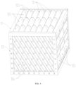
- a sedimentation plate including: a flat plate; a plurality of first rib plates, arranged at intervals, parallel to each other, and perpendicular to a first surface of the flat plate; and a plurality of second rib plates, arranged at intervals, parallel to each other, and perpendicular to a second surface of the flat plate; where, the first rib plates are perpendicular to the second rib plates; a water channel is formed between each two adjacent first rib plates; and a mud channel is formed between each two adjacent second rib plates.
- a height ratio of the first rib plate to the second rib plate is 1.5-5.
- the sedimentation plate is made of polyolefin.
- an interval between each two adjacent first rib plates is smaller than an interval between each two adjacent second rib plates.
- the second surface further protrudes to form a reinforcing rib that extends parallel to the second rib plate; and a height of the reinforcing rib is less than a height of the second rib plate.
- the present disclosure further provides a sedimentation assembly, including a box-type frame defined by a plurality of side beams and a plurality of sedimentation plates obliquely standing inside the box-type frame, where the sedimentation plate is the sedimentation plate described in the above technical solution; the first surface faces obliquely downward, and the second surface faces obliquely upward; and for each two adjacent sedimentation plates, the first rib plate of one sedimentation plate abuts against the second rib plate of the other sedimentation plate.
- an angle between the flat plate and a bottom surface of the box-type frame is 60°.
- At least one of the side beams is provided with a groove with an opening inclined to the bottom surface of the box-type frame; and the sedimentation plate is tightly inserted into the groove.
- the side beams are detachably connected by threaded fasteners.
- the sedimentation assembly further includes a flushing mechanism for injecting a flushing liquid into the mud channel;
- the flushing mechanism includes a bracket fixed above the side beams and a plurality of first flushing pipes installed on the bracket; and the first flushing pipes are horizontally arranged and provided with first water spray ports opening downward.
- the flushing mechanism further includes a plurality of second flushing pipes communicated with the first flushing pipes; and the plurality of second flushing pipes are erected on a side of the box-type frame and provided with second water spray ports facing the sedimentation plate.
- a plurality of second flushing pipes are erected on the side of the box-type frame adjacent to an upper end of the sedimentation plate.
- the present disclosure further provides a sedimentation module, including: a housing, provided with a water inlet, a water outlet, and a mud outlet; a sedimentation assembly, constructed as the sedimentation assembly described in the above technical solution, and provided inside the housing; and a sediment handling mechanism, provided below the sedimentation assembly to discharge settled sediment through the mud outlet.
- a sedimentation module including: a housing, provided with a water inlet, a water outlet, and a mud outlet; a sedimentation assembly, constructed as the sedimentation assembly described in the above technical solution, and provided inside the housing; and a sediment handling mechanism, provided below the sedimentation assembly to discharge settled sediment through the mud outlet.
- the sedimentation module further includes a water distribution mechanism, where the water distribution mechanism includes a first water distribution plate provided between a water input side of the sedimentation assembly and the water inlet and a second water distribution plate provided between a water output side of the sedimentation assembly and the water outlet; the first water distribution plate and the second water distribution plate divide the housing into a water input chamber, a sedimentation chamber accommodating the sedimentation assembly, and a water output chamber; and water distribution pipes are uniformly distributed on the first water distribution plate and the second water distribution plate in a penetrating manner to connect two adjacent chambers.
- the water distribution mechanism includes a first water distribution plate provided between a water input side of the sedimentation assembly and the water inlet and a second water distribution plate provided between a water output side of the sedimentation assembly and the water outlet; the first water distribution plate and the second water distribution plate divide the housing into a water input chamber, a sedimentation chamber accommodating the sedimentation assembly, and a water output chamber; and water distribution pipes are uniformly distributed on the first water distribution plate and the second water distribution plate in
- each of the first water distribution plate and the second water distribution plate is a hollow plate with a cavity; a surface of each of the first water distribution plate and the second water distribution plate facing the water channel is provided with a plurality of nozzles communicated with the cavity; positions of the nozzles correspond to a position of the water channel; and the first water distribution plate and the second water distribution plate are connected to a water supply pipe for supplying water to the cavity.
- the plurality of first rib plates and the plurality of second rib plates of the sedimentation plate are perpendicular to the flat plate.
- the first rib plates and the second rib plates can act as reinforcing ribs, which increase the rigidity of the sedimentation plate while reducing the thickness of the sedimentation plate.
- the also design reduces the difficulty of withdrawing during the production of the sedimentation plate, thereby improving production efficiency and reducing production costs.
- the mud channel of each sedimentation plate faces obliquely upward and the water channel thereof faces obliquely downward.
- the first rib plates on the upper sedimentation plate are perpendicular to the mud channel of the lower sedimentation plate.
- the first rib plates avoid blocking the mud channel.
- the design facilitates direct and rapid sedimentation of the sediment into the mud channel, thereby improving settling efficiency and increasing the utilization of the water flow cross-section of the water channel.
- the second rib plates stop in the water flow direction to prevent the sediment settled into the mud channel from re-entering the water flow, thereby improving the separation rate between the sediment and water.
- the sedimentation assembly of the present disclosure has the same technical effect as the sedimentation plate in the above technical solution, which is not described here to avoid unnecessary repetition.
- the sedimentation module provided by the present disclosure has the same technical effects as the sedimentation assembly in the above technical solution, which is not described here to avoid unnecessary repetition.
- the sediment discharged from the mud channel to the bottom of the housing is quickly discharged through the mud outlet under the guidance of the sediment handling mechanism, preventing the sediment from accumulating in the housing to clog the mud channel.
- orientation terms such as “upper” and “lower” are usually intended to indicate upper and lower positions along the direction of gravity, while “inner” and “outer” indicate inner and outer positions relative to the contour of the part.
- first and second are intended to distinguish one element from another and do not have order or importance.
- the sedimentation plate 10 includes flat plate 101.
- the flat plate 101 includes first surface 1011 and second surface 1012 that are opposite to each other.
- a plurality of first rib plates 102 are arranged at intervals, parallel to each other, and perpendicular to the first surface 1011.
- a plurality of second rib plates 103 are arranged at intervals, parallel to each other, and perpendicular to the second surface 1012 of the flat plate 101.
- the first rib plates 102 are perpendicular to the second rib plates 103.
- Water channel 104 is formed between each two adjacent first rib plates 102
- mud channel 105 is formed between each two adjacent second rib plates 103.
- the plurality of first rib plates 102 and the plurality of second rib plates 103 of the sedimentation plate 10 are perpendicular to the flat plate 101.
- the first rib plates 102 and the second rib plates 103 can act as reinforcing ribs, which increase the rigidity of the sedimentation plate 10 while reducing the thickness of the sedimentation plate 10.
- the also design reduces the difficulty of withdrawing during the production of the sedimentation plate 10, thereby improving production efficiency and reducing production costs.
- the mud channel 105 of each sedimentation plate 10 faces obliquely upward and the water channel 104 thereof faces obliquely downward.
- the first rib plates 102 on the upper sedimentation plate 10 are perpendicular to the mud channel 105 of the lower sedimentation plate 10. Therefore, along a sedimentation direction of sediment, the first rib plates 102 avoid blocking the mud channel 105.
- the design facilitates direct and rapid sedimentation of the sediment into the mud channel 105, thereby improving settling efficiency and increasing the utilization of the water flow cross-section of the water channel 104.
- the second rib plates 103 stop in the water flow direction to prevent the sediment settled into the mud channel 105 from re-entering the water flow, thereby improving the separation rate between the sediment and water.
- a height ratio of the first rib plate 102 to the second rib plate 103 is 1.5-5.
- the height of the first rib plate 102 and the second rib plate 103 refers to the size of a portion protruding from the flat plate.
- the height ratio of the first rib plate 102 to the second rib plate 103 is 16:9.
- the sedimentation plate 10 is made of polyolefin.
- the sedimentation plate can be made of polyvinyl chloride (PVC), polypropylene (PP) or polyethylene (PE).
- PVC polyvinyl chloride
- PP polypropylene
- PE polyethylene
- the sedimentation plate 10 can be molded in one piece by injection molding, and the sedimentation plate 10 is lightweight, facilitating transportation and assembly.
- the sedimentation plate 10 made of these materials also has corrosion resistance and long service life.
- an interval between each two adjacent first rib plates 102 is smaller than an interval between each two adjacent second rib plates 103. That is, the mud channel 105 is wider to avoid the mud channel 105 from being clogged by sediment.
- the second surface 1012 further protrudes to form reinforcing rib 106 that extends parallel to the second rib plate 103 to increase the strength of the sedimentation plate 10 and prevent bending deformation of the sedimentation plate 10 when there is a lot of sediment.
- the height of the reinforcing rib 106 is less than that of the second rib plate 103 to avoid interference of the reinforcing rib 106 with the water flow in the water channel 104.
- the surface of the first rib plate 102 can also form a reinforcing rib perpendicular to the flat plate 101 to prevent bending deformation of the first rib plate 102.
- the present disclosure further provides sedimentation assembly 1.
- the sedimentation assembly 1 includes box-type frame 11 defined by a plurality of side beams 111 and a plurality of sedimentation plates 10 obliquely standing inside the box-type frame 11.
- the sedimentation plate 10 is the sedimentation plate 10 in the above technical solution.
- the first surface 1011 faces obliquely downward, and the second surface 1012 faces obliquely upward.
- the first rib plate 102 of one sedimentation plate abuts against the second rib plate 103 of the other sedimentation plate.
- the water channel 104 and the mud channel 105 are mutually perpendicular, and the water channel 104 is above the mud channel 105.
- the sediment is settled into the mud channel 105 under the action of gravity.
- the mud channel 105 extends obliquely downward, and after entering the mud channel 105, the sediment flows downward and is discharged along the mud channel 105.
- the sedimentation assembly of the present disclosure has the same technical effect as the sedimentation plate in the above technical solution, which is not described here to avoid unnecessary repetition.
- the water flow direction is the same as the extension direction of the water channel 104.
- Water enters the water channel 104 from a water input side of the sedimentation assembly 1 and flows out of the water channel 104 from a water output side of the sedimentation assembly 1.
- the sedimentation assembly 1 is approximately a cube structure with a length of 2 m, a width of 3.6 m, and a height of 1.5 m. The length refers to the dimension along the water flow direction.
- the sedimentation assembly 1 can be used as a standard structure for convenient transportation and installation.
- the water flow velocity through the water channel 104 can be 8-10 mm/s to balance settling efficiency and productivity.
- an angle between the flat plate 101 and a bottom surface of the box-type frame 11 is 60°, such that an angle between the mud channel 105 and the bottom surface is greater than a dynamic angle of repose of the sediment, thereby preventing the sediment from being adhered to the mud channel 105.
- At least one of the side beams 111 is provided with a groove (not shown) with an opening inclined to the bottom surface of the box-type frame 11.
- the sedimentation plate 10 is tightly inserted into the groove and relatively fixed to the box-type frame 11.
- the sedimentation plate 10 is inserted into the groove to be assembled with the box-type frame 11, which reduces the assembly difficulty of the sedimentation assembly 1 and improves the assembly efficiency of the sedimentation assembly 1.
- the side beams 111 are detachably connected by threaded fasteners, facilitating the rapid disassembly and assembly of the box-type frame 11.
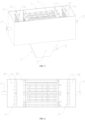
- the sedimentation assembly 1 further includes flushing mechanism 12 for injecting a flushing liquid into the mud channel 105.
- the flushing mechanism 12 includes bracket 121 fixed above the side beams 111 and a plurality of first flushing pipes 122 installed on the bracket 121.
- the first flushing pipes 122 are horizontally arranged and provided with a plurality of first water spray ports 123 opening downward.
- the plurality of first water spray ports 123 are arranged at intervals.
- the first flushing pipes 122 are communicated with a high-pressure water source to spray the flushing liquid through the first water spray ports 123 toward the mud channel 105.
- the flushing liquid flushes the sediment downward as it flows down the mud channel 105, thereby accelerating the discharge of the sediment.
- the sedimentation plates 10 are obliquely standing in the box-type frame 11. Therefore, an upper end of the mud channel 105 of at least one of the sedimentation plates 10 is located on a top surface of the box-type frame 11, while an upper end of the mud channel 105 of at least another sedimentation plate 10 is located on a side surface of the box-type frame 11. Since the first water spray ports 123 cannot spray the cleaning liquid into the mud channel 105 with its upper end located on the side surface of the box-type frame 11. As shown in FIGS. 2 and 7 , the flushing mechanism 12 further includes a plurality of second flushing pipes 124 communicated with the first flushing pipes 122.
- the plurality of second flushing pipes 124 are erected on a side of the box-type frame 11. Specifically, they are erected on the side adjacent to the upper end of the sedimentation plate 10 and provided with second water spray ports 125 facing the sedimentation plate 10. The second water spray ports 125 spray the flushing liquid into the mud channel 105 with its upper end located on the side surface of the box-type frame 11 so as to flush the sediment downward.
- the present disclosure further provides a sedimentation module.
- the sedimentation module includes housing 2, sedimentation assembly 1, and sediment handling mechanism 3.
- the sedimentation assembly 1 is the sedimentation assembly 1 in the above technical solution.
- the sedimentation assembly 1 is provided inside the housing 2.
- the housing 2 is provided with water inlet 21, water outlet 22, and mud outlet 23.
- the water inlet 21 is adjacent to the water input side of the sedimentation assembly 1
- the water outlet 22 is adjacent to the water output side of the sedimentation assembly 1
- the mud outlet 23 is provided at a bottom of the housing 2.
- the sediment handling mechanism 3 is provided below the sedimentation assembly 1 to discharge the settled sediment through the mud outlet 23.
- the sediment handling mechanism 3 is a funnel-shaped structure composed of a plurality of inclined mud guide plates 31.
- the mud outlet 23 is provided at a bottom of the funnel-shaped structure to facilitate smooth discharge of the sediment.
- the sedimentation module provided by the present disclosure has the same technical effects as the sedimentation assembly 1 in the above technical solution, which is not described here to avoid unnecessary repetition.
- the sediment discharged from the mud channel 105 to the bottom of the housing 2 is quickly discharged through the mud outlet 23 under the guidance of the sediment handling mechanism 3, preventing the sediment from accumulating in the housing 2 to clog the mud channel 105.
- the sedimentation module further includes water distribution mechanism 4.
- the water distribution mechanism 4 includes first water distribution plate 41 provided between the water input side of the sedimentation assembly 1 and the water inlet 21 and second water distribution plate 42 provided between the water output side of the sedimentation assembly 1 and the water outlet 22.
- the first water distribution plate 41 and the second water distribution plate 42 divide the housing 2 into water input chamber 201, sedimentation chamber 202 accommodating the sedimentation assembly 1, and water output chamber 203.
- Water distribution pipes 43 are uniformly distributed on the first water distribution plate 41 and the second water distribution plate 42 in a penetrating manner to connect two adjacent chambers.
- the evenly distributed water distribution pipes 43 on the first water distribution plate 41 evenly introduce water from the water input chamber 201 into the sedimentation chamber 202. In this way, the water flow enters a plurality of water channels 104 evenly and stably, ensuring the sedimentation stability.
- the evenly distributed water distribution pipes 43 on the second water distribution plate 42 evenly and stably introduce water from the sedimentation chamber 202 into the water output chamber 203, such that the settled water is stably and gently discharged through the water outlet 22 to the next process.
- each of the first water distribution plate 41 and the second water distribution plate 42 is a hollow plate with a cavity (not shown).
- a surface of each of the first water distribution plate 41 and the second water distribution plate 42 facing the water channel 104 is provided with a plurality of nozzles 44 communicated with the cavity.
- the positions of the nozzles 44 correspond to the position of the water channel 104.
- the first water distribution plate 41 and the second water distribution plate 42 are connected to water supply pipe 45 for supplying water to the cavity.
- the water supply pipe 45 is communicated with a high-pressure water source to spray high-pressure water through the nozzles 44 into the water channel 104 so as to clean the water channel 104.
Landscapes
- Chemical & Material Sciences (AREA)
- Chemical Kinetics & Catalysis (AREA)
- Sewage (AREA)
- Filtration Of Liquid (AREA)
Applications Claiming Priority (3)
| Application Number | Priority Date | Filing Date | Title |
|---|---|---|---|
| CN202111210735.3A CN113750579A (zh) | 2021-10-18 | 2021-10-18 | 一种侧向流平板沉淀模块 |
| CN202111583428.XA CN114405073B (zh) | 2021-10-18 | 2021-12-22 | 沉淀板、沉淀模组以及沉淀模块 |
| PCT/CN2022/125788 WO2023066218A1 (zh) | 2021-10-18 | 2022-10-17 | 沉淀板、沉淀模组以及沉淀模块 |
Publications (4)
| Publication Number | Publication Date |
|---|---|
| EP4403239A1 true EP4403239A1 (de) | 2024-07-24 |
| EP4403239A4 EP4403239A4 (de) | 2025-04-02 |
| EP4403239C0 EP4403239C0 (de) | 2025-11-05 |
| EP4403239B1 EP4403239B1 (de) | 2025-11-05 |
Family
ID=78799733
Family Applications (1)
| Application Number | Title | Priority Date | Filing Date |
|---|---|---|---|
| EP22882824.0A Active EP4403239B1 (de) | 2021-10-18 | 2022-10-17 | Niederschlagsplatte, niederschlagseinheit und niederschlagsmodul |
Country Status (5)
| Country | Link |
|---|---|
| US (1) | US12214300B2 (de) |
| EP (1) | EP4403239B1 (de) |
| JP (1) | JP7753562B2 (de) |
| CN (3) | CN113750579A (de) |
| WO (1) | WO2023066218A1 (de) |
Families Citing this family (5)
| Publication number | Priority date | Publication date | Assignee | Title |
|---|---|---|---|---|
| CN113750579A (zh) * | 2021-10-18 | 2021-12-07 | 山东华通环境科技股份有限公司 | 一种侧向流平板沉淀模块 |
| CN216798821U (zh) * | 2021-12-22 | 2022-06-24 | 山东华通环境科技股份有限公司 | 用于侧向流沉淀的配水装置和沉淀模块 |
| CN114681961A (zh) * | 2022-02-15 | 2022-07-01 | 新疆兵团勘测设计院(集团)有限责任公司 | 串联式斜板构造双层沉淀池 |
| WO2024227147A1 (en) * | 2023-04-28 | 2024-10-31 | Battelle Memorial Institute | Material separating assemblies and methods |
| CN117263347A (zh) * | 2023-11-08 | 2023-12-22 | 山东金镐源环保科技有限公司 | 一种污水处理池及沉淀机构 |
Family Cites Families (20)
| Publication number | Priority date | Publication date | Assignee | Title |
|---|---|---|---|---|
| US3491892A (en) * | 1968-04-15 | 1970-01-27 | Neptune Microflo Inc | Multichannel device for liquid treatment |
| US3615025A (en) * | 1969-12-19 | 1971-10-26 | Neptune Microfloc Inc | Solids-liquid separator with vertically spaced tube-settlers |
| JPS49119267A (de) * | 1973-03-17 | 1974-11-14 | ||
| US3898164A (en) * | 1974-06-24 | 1975-08-05 | Neptune Microfloc Inc | Perforated tube module for liquid treatment |
| NL9301589A (nl) * | 1993-09-14 | 1995-04-03 | Hollandsche Betongroep Nv | Bezinkinrichting met plaatseparator. |
| US5736037A (en) * | 1996-08-29 | 1998-04-07 | Meurer; Charles Lonnie | Foldable tube settler and method of installing tube settler |
| US6817476B2 (en) | 2003-01-31 | 2004-11-16 | Aerex Industries, Inc. | Water clarification system |
| CN100551482C (zh) | 2006-11-24 | 2009-10-21 | 珠海九通水务有限公司 | 水平管沉淀分离装置 |
| CN201370979Y (zh) | 2009-01-19 | 2009-12-30 | 大连绿诺环境工程科技有限公司 | 三级连续沉降斜板管沉淀器 |
| CN102284200A (zh) | 2011-06-07 | 2011-12-21 | 珠海九通水务有限公司 | 装填水平管沉淀分离装置的沉淀池 |
| DE102013101848A1 (de) | 2013-02-25 | 2014-08-28 | Faritec GmbH & Co. KG | Lamellenklärer |
| CN105617725B (zh) * | 2016-03-24 | 2017-07-21 | 许红兵 | 斜板沉淀装置及沉淀池 |
| CN106215469B (zh) | 2016-09-21 | 2019-08-02 | 武汉兴天宇环境股份有限公司 | 一种浸入式沉淀装置及沉淀系统 |
| CN106310728A (zh) | 2016-11-19 | 2017-01-11 | 无锡博进精密机械制造有限公司 | 带清洗功能的水处理箱 |
| CN106943776A (zh) * | 2017-05-03 | 2017-07-14 | 刘文义 | 侧向流斜管沉淀分离装置及沉淀池 |
| CN110711409B (zh) * | 2019-10-28 | 2024-09-03 | 北京北排装备产业有限公司 | 一种多向流沉淀单元及其使用方法 |
| CN213555521U (zh) * | 2020-10-20 | 2021-06-29 | 邵永玲 | 一种环保污水处理填料斜板式污水沉淀池 |
| CN112426756A (zh) | 2020-11-19 | 2021-03-02 | 李济平 | 一种污水处理用沉淀装置 |
| KR102295811B1 (ko) * | 2021-04-14 | 2021-08-31 | 효림산업주식회사 | 모듈형 라비린스 경사판 침전장치 |
| CN113750579A (zh) | 2021-10-18 | 2021-12-07 | 山东华通环境科技股份有限公司 | 一种侧向流平板沉淀模块 |
-
2021
- 2021-10-18 CN CN202111210735.3A patent/CN113750579A/zh active Pending
- 2021-12-22 CN CN202111583428.XA patent/CN114405073B/zh active Active
- 2021-12-22 CN CN202123254296.4U patent/CN216798810U/zh active Active
-
2022
- 2022-10-17 EP EP22882824.0A patent/EP4403239B1/de active Active
- 2022-10-17 WO PCT/CN2022/125788 patent/WO2023066218A1/zh not_active Ceased
- 2022-10-17 JP JP2024546355A patent/JP7753562B2/ja active Active
- 2022-10-17 US US18/701,665 patent/US12214300B2/en active Active
Also Published As
| Publication number | Publication date |
|---|---|
| EP4403239C0 (de) | 2025-11-05 |
| JP2024537549A (ja) | 2024-10-10 |
| JP7753562B2 (ja) | 2025-10-14 |
| CN216798810U (zh) | 2022-06-24 |
| CN114405073B (zh) | 2023-07-25 |
| EP4403239B1 (de) | 2025-11-05 |
| US12214300B2 (en) | 2025-02-04 |
| US20240325944A1 (en) | 2024-10-03 |
| EP4403239A4 (de) | 2025-04-02 |
| WO2023066218A1 (zh) | 2023-04-27 |
| CN113750579A (zh) | 2021-12-07 |
| CN114405073A (zh) | 2022-04-29 |
Similar Documents
| Publication | Publication Date | Title |
|---|---|---|
| EP4403239A1 (de) | Niederschlagsplatte, niederschlagseinheit und niederschlagsmodul | |
| CN108545844B (zh) | 一种污水处理的节能高效多重曝气系统及其方法 | |
| CN103285630A (zh) | 均匀布水均匀收水的斜板沉淀池 | |
| CN218478605U (zh) | 一种脉冲曝气装置 | |
| WO2015135503A1 (zh) | 一种液体导流装置 | |
| CN114751505A (zh) | 具有保险缺口的脉冲曝气装置 | |
| US9233865B2 (en) | Bioreactor comprising a mixing chamber | |
| CN203291567U (zh) | 均匀布水均匀收水的斜板沉淀池 | |
| CN219836149U (zh) | 沉降腔 | |
| CN212914627U (zh) | 一种移动式高速泥水分离设备 | |
| CN216798821U (zh) | 用于侧向流沉淀的配水装置和沉淀模块 | |
| CN216499202U (zh) | 导流型非金属液体分布器 | |
| CN214344966U (zh) | 一种汽水分流装置 | |
| CN211863979U (zh) | 沉淀池进水区结构 | |
| CN221734185U (zh) | 一种双氧水树脂清洗装置 | |
| CN205995091U (zh) | 一种均布沉淀池 | |
| CN223209058U (zh) | 一种色母料挤出机冷凝水沉淀池 | |
| CN218572883U (zh) | 一种脱出率及脱气率高的脱气罐 | |
| CN102649103B (zh) | 一种多边形筒体的旋流喷射浮选柱 | |
| CN219840631U (zh) | 一种高产量原油稳定塔 | |
| CN220939251U (zh) | 一种泥水分离循环水箱 | |
| CN223833406U (zh) | 一种高效稳流的浇铸溜槽 | |
| CN114394663B (zh) | 布气装置 | |
| CN222657859U (zh) | 一种砂水分离器 | |
| CN205516659U (zh) | 一种多级废水处理池 |
Legal Events
| Date | Code | Title | Description |
|---|---|---|---|
| STAA | Information on the status of an ep patent application or granted ep patent |
Free format text: STATUS: THE INTERNATIONAL PUBLICATION HAS BEEN MADE |
|
| PUAI | Public reference made under article 153(3) epc to a published international application that has entered the european phase |
Free format text: ORIGINAL CODE: 0009012 |
|
| STAA | Information on the status of an ep patent application or granted ep patent |
Free format text: STATUS: REQUEST FOR EXAMINATION WAS MADE |
|
| 17P | Request for examination filed |
Effective date: 20240416 |
|
| AK | Designated contracting states |
Kind code of ref document: A1 Designated state(s): AL AT BE BG CH CY CZ DE DK EE ES FI FR GB GR HR HU IE IS IT LI LT LU LV MC ME MK MT NL NO PL PT RO RS SE SI SK SM TR |
|
| DAV | Request for validation of the european patent (deleted) | ||
| DAX | Request for extension of the european patent (deleted) | ||
| A4 | Supplementary search report drawn up and despatched |
Effective date: 20250228 |
|
| RIC1 | Information provided on ipc code assigned before grant |
Ipc: B01D 21/00 20060101ALI20250224BHEP Ipc: B01D 21/04 20060101AFI20250224BHEP |
|
| GRAP | Despatch of communication of intention to grant a patent |
Free format text: ORIGINAL CODE: EPIDOSNIGR1 |
|
| STAA | Information on the status of an ep patent application or granted ep patent |
Free format text: STATUS: GRANT OF PATENT IS INTENDED |
|
| INTG | Intention to grant announced |
Effective date: 20250626 |
|
| GRAS | Grant fee paid |
Free format text: ORIGINAL CODE: EPIDOSNIGR3 |
|
| GRAA | (expected) grant |
Free format text: ORIGINAL CODE: 0009210 |
|
| STAA | Information on the status of an ep patent application or granted ep patent |
Free format text: STATUS: THE PATENT HAS BEEN GRANTED |
|
| AK | Designated contracting states |
Kind code of ref document: B1 Designated state(s): AL AT BE BG CH CY CZ DE DK EE ES FI FR GB GR HR HU IE IS IT LI LT LU LV MC ME MK MT NL NO PL PT RO RS SE SI SK SM TR |
|
| P01 | Opt-out of the competence of the unified patent court (upc) registered |
Free format text: CASE NUMBER: UPC_APP_8321_4403239/2025 Effective date: 20250929 |
|
| REG | Reference to a national code |
Ref country code: CH Ref legal event code: F10 Free format text: ST27 STATUS EVENT CODE: U-0-0-F10-F00 (AS PROVIDED BY THE NATIONAL OFFICE) Effective date: 20251105 Ref country code: GB Ref legal event code: FG4D |
|
| REG | Reference to a national code |
Ref country code: DE Ref legal event code: R096 Ref document number: 602022024667 Country of ref document: DE |
|
| REG | Reference to a national code |
Ref country code: IE Ref legal event code: FG4D |
|
| U01 | Request for unitary effect filed |
Effective date: 20251203 |
|
| U07 | Unitary effect registered |
Designated state(s): AT BE BG DE DK EE FI FR IT LT LU LV MT NL PT RO SE SI Effective date: 20251211 |
|
| P04 | Withdrawal of opt-out of the competence of the unified patent court (upc) registered |
Free format text: CASE NUMBER: UPC_APP_8321_4403239_1/2025 Effective date: 20251211 |