EP4403207A1 - Elektrisches muskelstimulationssystem mit am körper tragbarem elektrischem unterwassermuskelstimulationsanzug - Google Patents
Elektrisches muskelstimulationssystem mit am körper tragbarem elektrischem unterwassermuskelstimulationsanzug Download PDFInfo
- Publication number
- EP4403207A1 EP4403207A1 EP21908119.7A EP21908119A EP4403207A1 EP 4403207 A1 EP4403207 A1 EP 4403207A1 EP 21908119 A EP21908119 A EP 21908119A EP 4403207 A1 EP4403207 A1 EP 4403207A1
- Authority
- EP
- European Patent Office
- Prior art keywords
- buoy
- muscle stimulation
- electrical muscle
- communication module
- module
- Prior art date
- Legal status (The legal status is an assumption and is not a legal conclusion. Google has not performed a legal analysis and makes no representation as to the accuracy of the status listed.)
- Withdrawn
Links
Images


Classifications
-
- A—HUMAN NECESSITIES
- A41—WEARING APPAREL
- A41D—OUTERWEAR; PROTECTIVE GARMENTS; ACCESSORIES
- A41D1/00—Garments
-
- A—HUMAN NECESSITIES
- A41—WEARING APPAREL
- A41D—OUTERWEAR; PROTECTIVE GARMENTS; ACCESSORIES
- A41D7/00—Bathing gowns; Swim-suits, drawers, or trunks; Beach suits
-
- A—HUMAN NECESSITIES
- A61—MEDICAL OR VETERINARY SCIENCE; HYGIENE
- A61N—ELECTROTHERAPY; MAGNETOTHERAPY; RADIATION THERAPY; ULTRASOUND THERAPY
- A61N1/00—Electrotherapy; Circuits therefor
- A61N1/02—Details
- A61N1/04—Electrodes
-
- A—HUMAN NECESSITIES
- A61—MEDICAL OR VETERINARY SCIENCE; HYGIENE
- A61N—ELECTROTHERAPY; MAGNETOTHERAPY; RADIATION THERAPY; ULTRASOUND THERAPY
- A61N1/00—Electrotherapy; Circuits therefor
- A61N1/02—Details
- A61N1/04—Electrodes
- A61N1/0404—Electrodes for external use
- A61N1/0408—Use-related aspects
- A61N1/0452—Specially adapted for transcutaneous muscle stimulation [TMS]
-
- A—HUMAN NECESSITIES
- A61—MEDICAL OR VETERINARY SCIENCE; HYGIENE
- A61N—ELECTROTHERAPY; MAGNETOTHERAPY; RADIATION THERAPY; ULTRASOUND THERAPY
- A61N1/00—Electrotherapy; Circuits therefor
- A61N1/02—Details
- A61N1/04—Electrodes
- A61N1/0404—Electrodes for external use
- A61N1/0472—Structure-related aspects
- A61N1/0484—Garment electrodes worn by the patient
-
- A—HUMAN NECESSITIES
- A61—MEDICAL OR VETERINARY SCIENCE; HYGIENE
- A61N—ELECTROTHERAPY; MAGNETOTHERAPY; RADIATION THERAPY; ULTRASOUND THERAPY
- A61N1/00—Electrotherapy; Circuits therefor
- A61N1/18—Applying electric currents by contact electrodes
- A61N1/32—Applying electric currents by contact electrodes alternating or intermittent currents
- A61N1/36—Applying electric currents by contact electrodes alternating or intermittent currents for stimulation
- A61N1/36003—Applying electric currents by contact electrodes alternating or intermittent currents for stimulation of motor muscles, e.g. for walking assistance
-
- A—HUMAN NECESSITIES
- A61—MEDICAL OR VETERINARY SCIENCE; HYGIENE
- A61N—ELECTROTHERAPY; MAGNETOTHERAPY; RADIATION THERAPY; ULTRASOUND THERAPY
- A61N1/00—Electrotherapy; Circuits therefor
- A61N1/18—Applying electric currents by contact electrodes
- A61N1/32—Applying electric currents by contact electrodes alternating or intermittent currents
- A61N1/36—Applying electric currents by contact electrodes alternating or intermittent currents for stimulation
- A61N1/36014—External stimulators, e.g. with patch electrodes
- A61N1/3603—Control systems
Definitions
- the present disclosure relates to an electrical muscle stimulation system in which a buoy module floating on water is connected to an electrical muscle stimulation suit, which is worn by a user under water, to wirelessly make communication with a control device.
- an electrical muscle stimulation (EMS) device has been attached to a partial surface region of a human body and used to enhance effects of a massage, treatment, an exercise.
- the EMS may be expected in rapidly enhancing strength of a muscle of a user and rapidly recovering the fatigue of the muscle of the user without requiring an additional exercise or without a burden on a joint due to the exercise, by electrically stimulating muscles adjacent to the attached place to contract the muscles.
- An aspect of the present disclosure may provide an electrical muscle stimulation system, capable of transmitting, to an electrical muscle stimulation suit, a wireless control signal of a control device more securely and seamlessly, even if a user is equipped with the electrical muscle stimulation suit under water.
- Another aspect of the present disclosure may provide an electrical muscle stimulation system capable of lowering the risk in which the communication module or the power supply unit connected to the electrical muscle stimulation suit is submerged, as the communication module or the power supply unit is positioned outside water, and of more simply exhibiting a waterproof effect, even if the user is equipped with the electrical muscle stimulation suit under water.
- an electrical muscle stimulation system may include an electrical muscle stimulation suit to be worn by a user under water, a control device to generate a wireless control signal for controlling an operation of the electrical muscle stimulation suit, and a buoy module to float on a surface of the surface.
- the electrical muscle stimulation suit may include at least one electrode pad attached to a region corresponding to each muscle part of the user, the buoy module may include a first communication module provided at a position of the buoy module, for transmitting the wireless control signal through air, without passing through water, and the wireless control signal may be transmitted to the electrode pad through wired connection to the electrode pad.
- the electrical muscle stimulation system may further include a waterproof cable connected between the buoy module and the electrical muscle stimulation suit to transmit the wireless control signal from the buoy module to the electrode pad.
- the first communication module may be provided in an upper end region of the buoy module which is not submerged, and the waterproof cable may be connected to a lower region of the buoy module.
- the waterproof cable may be detachable from the electrical muscle stimulation suit.
- the electrical muscle stimulation system may further include a processor.
- the electric muscle stimulation suit may include a second communication module to receive the wireless con troll signal, and the processor may control the second communication module to receive the wireless control signal through the second communication module, when the waterproof cable is separated.
- the electrical muscle stimulation system may further include a processor
- the buoy module may include a first submerging sensor to sense whether the first communication module is submerged
- the processor may include control the first communication module to be turned off, when a submerging sensing signal is received from the first submerging sensor
- the electrical muscle stimulation suit may include a second communication module to receive the wireless con troll signal, and a second submerging sensor to sense whether the second communication module is submerged
- the processor may control the second communication module to receive the wireless control signal through the second communication module, when receiving the submerging sensing signal from the first submerging sensor, instead of receiving the submerging sensing signal form the second submerging sensor, and control the first communication module to receive the wireless control signal through the first communication module, when receiving the submerging sensing signal from the second submerging sensor, instead of receiving the submerging sensing signal from the first submerging sensor.
- the electrical muscle stimulation suit may include a second communication module to transmit a buoy module connection request signal to the control device, when at least one of the buoy module or the waterproof cable is not electrically connected to the electrical muscle stimulation suit.
- control device may include a notification unit to notify a buoy module connection request message to a user, when receiving the buoy module connection request signal
- the buoy module may include a buoy device provided in the first communication module, and a waterproof case to receive the buoy device, such that the buoy device is sealed from an outside to prevent the buoy device from being submerged.
- the buoy device may include a power supply unit to supply power to the electrical muscle stimulation suit.
- the buoy device may include a first submerging sensor to sense whether the first communication module is submerged.
- the buoy module further may include a floating unit to be detachable from the waterproof case, and the floating unit may be configured such that additional buoyancy is applied to the buoy module in addition to the buoyancy caused by the waterproof case.
- the wireless control signal of the control device may be transmitted to the electrical muscle stimulation suit more securely and seamlessly, even if the user is equipped with the electrical muscle stimulation suit under water.
- the risk in which the communication module or the power supply unit connected to the electrical muscle stimulation suit is submerged, may be lowered, as the communication module or the power supply unit is positioned outside water, and the waterproof effect may be more simply exhibited, even if the user is equipped with the electrical muscle stimulation suit under water.
- ⁇ module or “-unit” may be implemented in software or hardware. According to embodiments, a plurality of modules and a plurality of parts can be implemented by using one component or one module or one part can include a plurality of components.
- module or “-unit” used herein may refer to software, field programmable gate array (FPGA), or hardware component serving as a unit to perform at least one function or operation.
- a function provided in the term “-module” or “-unit” may be performed separately in the form of a plurality of components or “-unit”, and may be integrated with another additional component.
- the term “-module” or “-unit” may be configured to exist in an addressable storage medium without the limitation to software or hardware or may be configured to operate one or more processors.
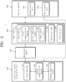
- FIG. 1 is a view illustrating an electrical muscle stimulation system according to an embodiment.
- the electrical muscle stimulation system 1 may include an electrical muscle stimulation suit 100, a waterproof cable 200, a buoy module 300, and a control device 400.
- an electrical muscle stimulation device is used in a manner to apply appropriate electrical simulation to each muscle of a user, as the user wears a suit-form device in the air.
- the user may receive underwater health care or underwater rehabilitation in a manner of electrically stimulating the muscle of the user in the state that the user equipped with the electrical muscle simulation device enters water.
- the electrical muscle stimulation suit 100 may be worn by a user under water. Meanwhile, the electrical muscle stimulation suit 100 may be worn and used even in the air outside the water according to a user selection.
- the control device 400 may generate a wireless control signal for controlling an operation of the electrical muscle stimulation suit 100.
- the communication unit 410 provided in the control device 400 may transmit various wireless control signals to the buoy module 300 and the electrical muscle stimulation suit 100 or receive various wireless control signals through a wireless communication network.
- the wireless control signal refers to a wireless signal wireless transmitted and received between various communication modules.
- the wireless control signal includes, but is not limited to, a Wi-Fi signal, a 3G signal, a 4G signal, or a 5G signal.
- the buoy module 300 may be configured to float on the surface of water.
- the user may naturally float the buoy module 300 on the surface of water such as the pool, as the user wearing the suit enters the swimming pool.
- the buoy module 300 may float on water because the density thereof is lower than the density of water used, based on the overall volume.
- FIG. 2 is a block diagram of an electrical muscle stimulation system according to an embodiment.
- the electrical muscle stimulation suit 100 may include at least one electrode pad 110 attached to a region corresponding to each muscle part of the user.
- the buoy module 300 may include a first communication module 311.
- the first communication module 311 may be provided at a position of the buoy module 300, for transmitting a wireless control signal through air, without passing through water.
- the buoy module 300 may be wired to the electrode pad 110 to transmit the wireless control signal, which is received by the first communication module 311, to the electrode pad 110.
- Each electrode pad 110 may provide electrical stimulation to a human body depending on mutually different current intensities or frequencies, based on the wireless control signal.
- the control device 400 may separately set a master level and a level for each part.
- the master level may be a level for controlling the current intensity and frequency of the entire electrode pad 110
- the level for each part may be a level for controlling the current intensity and frequency of each of the electrode pads 110.
- the control device 400 may be, but is not limited to, a user terminal in which an electrical muscle stimulation application is installed.
- the buoy module 300 may include a buoy device 310, a waterproof case 320, and a floating unit 330.
- the buoy device 310 may include the first communication module 311, a first submerging sensor 312, and a power supply unit 313.
- the electrical muscle stimulation system 1 may include a waterproof cable 200 connected between the buoy module 300 and the electrical muscle stimulation suit 100 to transmit the wireless control signal from the buoy module 300 to the electrode pad 110.
- the waterproof cable 200 may be configured to be detachable from the electrical muscle stimulation suit 100.
- the electrical muscle stimulation suit 100 may include a second communication module 120 configured to receive the wireless control signal.
- the second communication module 120 may transmit the received wireless control signal to the electrode pad 110.
- the electrical muscle stimulation system 1 may include a processor.
- the processor may be provided in any one of the components, such as the electrical muscle stimulation suit 100, the control device 400, and the buoy module 300, of the electrical muscle stimulation system 1, and a plurality of processors may be provided in the electrical muscle stimulation suit 100, the control device 400, and the buoy module 300.
- the processor may control the second communication module 120 to receive the wireless control signal through the second communication module 120, when the waterproof cable 200 is separated from one of the electrical muscle stimulation suit 100 or the buoy module 300.
- the second communication module 120 provided in the electrical muscle stimulation suit 100 may receive a wireless control signal to control the electrode pad 110.
- the buoy device 310 may include the first submerging sensor 312.
- the first submerging sensor 312 may sense whether the first communication module 311 is submerged. When the first communication module 311 is submerged, the first submerging sensor 312 may generate a submerging sensing signal and transmit the submerging sensing signal to the processor.
- the processor may control the first communication module 311 such that the first communication module 311 is turned off, when the submerging sensing signal is received from the first submerging sensor 312.
- the electrical muscle stimulation suit 100 may include a second submerging sensor 130.
- the second submerging sensor 130 may sense whether the second communication module 120 is submerged.
- the processor may control the second communication module 120 to receive a wireless control signal through the second communication module 120.
- the processor may control the first communication module 311 to receive the wireless control signal through the first communication module 311.
- the electrical muscle stimulation system 1 may selectively use the communication module of the buoy module 300 or the communication module of the electrical muscle stimulation suit 100, depending on whether an inner part of the buoy module 300 or the electrical muscle stimulation suit 10 is submerged, due to carelessness or damage of the user, such that safe treatment or rehabilitation may be provided to the user.
- the second communication module 120 may transmit a buoy module connection request signal to the control device 400, when at least one of the buoy module 300 or the waterproof cable 200 is not electrically connected to the electrical muscle stimulation suit 100.
- the control device 400 may include a notification unit 420.
- the notification unit 420 may be a component which notifies various types of information to a user.
- the notification unit 420 may notify the information to the user, regardless of any one of a manner of displaying information on a display screen or a manner of outputting a sound through a speaker.
- the notification unit 420 may notify the buoy module connection request message to user.
- the buoy module connection request message may be displayed on a display, or may be output in the form of a sound from a speaker.
- the method for controlling the electrical stimulation system according to the embodiment of the present disclosure described until now and an embodiment described to be described may be implemented in the form of a program which may be driven by a processor.
- the program may include program instructions, data files, data structures, etc. independently or may include a combination thereof.
- the program may be designed and implemented by using machine codes or high-level language codes.
- the program may be specifically designed to implement a method for correcting the above-described signs or may be implemented by using various functions or definitions which are well known or available to those skilled in a computer software field.
- the program for implementing the method for indicating the above-described information may be recoded in a recording medium readable by the processor.
- the recording medium may be a memory.
- the memory may store a program for executing the above-described operation and the operation to be described.
- the memory is to execute the stored program.
- the memory may include a volatile memory such as a static random access memory (S-RAM) to temporarily memorize data or a dynamic random access memory (D-RAM).
- the memory may include a non-volatile memory, such as a read only memory (ROM), an erasable programmable read only memory (EPROM), an electrically erasable programmable read only (EEPROM) to store a control program and control data in a long term.
- the processor may include various logic circuits and computing circuits, may process data depending on a program provided from the memory, and may generate a control signal depending on the processing result.
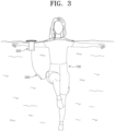
- FIG. 3 is a view illustrating a user using an electric muscle stimulation suit and a buoy according to an embodiment.
- a user may receive treatment in a swimming pool while wearing the electrical muscle stimulation suit 100.
- the control device 400 and the electrical muscle stimulation suit 100 may not smoothly make communication with each other.
- the communication module which receives the wireless control signal of the control device 400 and transmits the wireless control signal to the electrical muscle stimulation suit 100, may be positioned on the water surface or be at least close to the water surface, the communication module may smoothly receive the wireless control signal.
- the first communication module 311 may be positioned on the water surface.
- the signal wirelessly received by the first communication module 311 from the control device 400 may be transmitted to the electrical muscle stimulation suit 100, which is positioned under the water surface, through the waterproof cable 200.
- the electrical muscle stimulation suit 100 may wirelessly receive the control signal.
- the communication module may receive the wireless control signal from the control device 400 without distortion or interruption of the signal.
- the risk in which the communication module or the power supply unit 313 is submerged may be lowered.
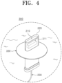
- FIG. 4 is a view illustrating a buoy module floating on a water surface according to an embodiment.
- the buoy module 300 may be configured in a form in which the buoy device 310, the waterproof case 320, and the floating unit 330 are combined.
- the first communication module 311 may be provided in an upper end region of the buoy module 300 which is not submerged. Specifically, the first communication module 311 may be provided in a region positioned on the water surface, even in the buoy device 310, when the buoy module 300 is floating under water.
- the first communication module 311 since the first communication module 311 is provided in a region, which is positioned on the water surface, of the buoy device 310, the first communication module 311 may wirelessly receive a control signal through the air, without worrying about signal distortion or disconnection due to water.
- the waterproof cable 200 may be configured to be connected to a lower region of the buoy module 300.
- the waterproof cable 200 may be connected to a lower end region of the buoy module 300, to continuously maintain the center of gravity of the buoy module 300 to be stable, such that the buoy module 300 is not overturned.
- the first communication module 311 of the buoy module 300 may be continuously positioned outside the water to stably receive the wireless control signal.
- the floating unit 330 may be configured to be detachable from the waterproof case 320.
- the floating unit 330 may be configured such that additional buoyancy is applied to the buoy module 300 in addition to the buoyancy caused by the waterproof case 320.
- the floating unit 330 may be connected to the outside of the waterproof case 320 to provide additional buoyancy to the buoy module 300.
- the floating unit 330 may be configured to stably float on the water surface without being overturned or severely shaken.
- the buoy module 300 is not necessarily configured in a form in which the buoy device 310, the waterproof case 320, and the floating unit 330 are combined.
- the buoy module 300 may be configured in a form in which the buoy device 310 is provided inside the waterproof case 320 and combined with the waterproof case 320.
- the buoy module 300 may include only one buoy device 310.
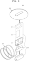
- FIG. 5 is a view illustrating a process of assembling the buoy module by combining the buoy device and the waterproof case 320 according to an embodiment.
- the buoy module 300 may be simply assembled by coupling the buoy device 310, such that the buoy device 310 is positioned inside the waterproof case 320.
- the waterproof case 320 may receive the buoy device 310 such that the buoy device 310 is sealed from the outside to be prevented from being submerged.
- the buoy device 310 may be provided inside the waterproof case 320, and the waterproof case 320 may be sealed to prevent external water from flowing into the waterproof case 320.
- the waterproof case 320 may be formed by coupling two closely contactable components to each other. Accordingly, when the waterproof case 310 is not used, the two components are simply coupled to each other through a hinge. When the waterproof case is used, the two components make close contact with each other, such that the inner part of the waterproof case 320 is sealed from the outside.
- the waterproof cable 200 connected to the buoy device 310 may extend from the inside of the waterproof case 320 to the outside of the waterproof case 320, through a through hole provided in the waterproof case 320.
- a rubber material may be provided in the contact region between the waterproof cable 200 and the waterproof case 320 to maintain the inside of the waterproof cable 200 to be sealed such that a gap is not formed.
- the shape of the waterproof case 320 is not limited to those illustrated in FIG. 5 , and a manner in which the buoy device 310 and the waterproof case 320 are coupled to each other is not limited to those illustrated in FIG. 5 .
- FIG. 6 is a view illustrating a configuration of a buoy module, according to an embodiment.
- the waterproof case 320 may be separately divided into two or more components, such as a main body and a lid, when not used, and the inner part of the waterproof case 320 may be sealed from the outside, as the lid is covered on the main body, when used.
- the waterproof cable 200 connected to the buoy device 310 may be connected from the inside of the waterproof case 320 to the outside of the waterproof case 320 through the through the hole provided in the lid.
- the end of the waterproof cable 200 connected to the buoy device 310 may be configured as a portion, which functions as a lid, of the waterproof case 320.
- the buoy device 310 may include the power supply unit 313 configured to supply power to the electrical muscle stimulation suit 100.
- the power supply unit 313 may include a large-capacity battery.
- the power supply unit 313 is positioned in the buoy device 310 rather than the electrical muscle stimulation suit 100 submerged under water, such that power is more safely supplied to the electrode pad 110.
- the waterproof case 320 having the buoy device 310 mounted therein and covered and sealed with the lid may be coupled to the floating unit 330.
- the waterproof case 320 may be coupled to the floating unit 330, as an outer surface of the waterproof case 320 is merely fitted into a through hole provided in the floating unit 330, the coupling scheme between the waterproof case 320 and the floating unit 330 is not limited thereto. In other words, as long as the floating unit 330 is configured to apply additional buoyancy to the buoy module 300 in addition to the buoyancy caused by the waterproof case 320, the waterproof case 320 and the floating unit 330 may be coupled to each other through various coupling schemes.
- the buoy module 300 is not one single detachable device.
- the buoy module 300 is basically divided into the buoy device 310, the waterproof case 320, and the floating unit 330.
- the user may put the buoy device 310 into the waterproof case 320, may close and seal the lid of the waterproof case 320, may mount the floating unit 330 in the waterproof case 320, thereby simply manufacturing the buoy module 300.
- the user may dismantle the buoy module 300 such that the buoy device 310 is separated from the waterproof case 320 and the floating unit 330, and may only the buoy device 310.
- At least one component may be added or deleted to correspond to the performance of the components described above. Furthermore, it will be easily understood by a person with ordinary skill in the art to which the present disclosure pertains that the mutual positions of components may be changed to correspond to the performance or structure of the system.
Landscapes
- Health & Medical Sciences (AREA)
- Life Sciences & Earth Sciences (AREA)
- Engineering & Computer Science (AREA)
- Biomedical Technology (AREA)
- Nuclear Medicine, Radiotherapy & Molecular Imaging (AREA)
- Radiology & Medical Imaging (AREA)
- Animal Behavior & Ethology (AREA)
- General Health & Medical Sciences (AREA)
- Public Health (AREA)
- Veterinary Medicine (AREA)
- Physical Education & Sports Medicine (AREA)
- Biophysics (AREA)
- Heart & Thoracic Surgery (AREA)
- Textile Engineering (AREA)
- Electrotherapy Devices (AREA)
Applications Claiming Priority (3)
| Application Number | Priority Date | Filing Date | Title |
|---|---|---|---|
| KR20210123852 | 2021-09-16 | ||
| KR1020210169705A KR102663464B1 (ko) | 2021-09-16 | 2021-12-01 | 수중에서 착용 가능한 전기적 근육 자극 슈트를 포함하는 전기적 근육 자극 시스템 |
| PCT/KR2021/095121 WO2023042979A1 (ko) | 2021-09-16 | 2021-12-13 | 수중에서 착용 가능한 전기적 근육 자극 슈트를 포함하는 전기적 근육 자극 시스템 |
Publications (2)
| Publication Number | Publication Date |
|---|---|
| EP4403207A1 true EP4403207A1 (de) | 2024-07-24 |
| EP4403207A4 EP4403207A4 (de) | 2025-05-14 |
Family
ID=85603034
Family Applications (1)
| Application Number | Title | Priority Date | Filing Date |
|---|---|---|---|
| EP21908119.7A Withdrawn EP4403207A4 (de) | 2021-09-16 | 2021-12-13 | Elektrisches muskelstimulationssystem mit am körper tragbarem elektrischem unterwassermuskelstimulationsanzug |
Country Status (3)
| Country | Link |
|---|---|
| US (1) | US12280252B2 (de) |
| EP (1) | EP4403207A4 (de) |
| WO (1) | WO2023042979A1 (de) |
Family Cites Families (13)
| Publication number | Priority date | Publication date | Assignee | Title |
|---|---|---|---|---|
| US4927041A (en) * | 1988-07-15 | 1990-05-22 | Hepburn Michael J | Self-stabilizing floating cooler |
| JP4500900B2 (ja) * | 2002-10-24 | 2010-07-14 | 小川 秀和 | 整復装置および衣類 |
| JP2007133459A (ja) * | 2005-11-08 | 2007-05-31 | Yamaguchi Univ | 入浴監視装置 |
| JP5144224B2 (ja) * | 2007-11-15 | 2013-02-13 | 国立大学法人 筑波大学 | 入浴監視システム |
| RU2415054C1 (ru) * | 2009-12-28 | 2011-03-27 | Учреждение Российской академии наук Государственный Научный Центр РФ Институт медико-биологических проблем РАН | Тренировочный/лечебный низкочастотный электромиостимуляционный костюм |
| WO2016131935A1 (de) * | 2015-02-18 | 2016-08-25 | Wearable Life Science Gmbh | System zur steuerung von stimulations-impulsen |
| US10806925B2 (en) * | 2015-02-27 | 2020-10-20 | Mtg Co., Ltd. | Muscle electrostimulation device |
| WO2016154271A1 (en) * | 2015-03-23 | 2016-09-29 | Tau Orthopedics, Llc | Dynamic proprioception |
| AU2017238726A1 (en) | 2016-03-22 | 2018-11-08 | Powerdot, Inc. | Compact muscle stimulator |
| KR102103052B1 (ko) * | 2016-08-05 | 2020-04-21 | 오병선 | 수중 헬스케어용 저주파 자극기 |
| US9662489B1 (en) * | 2016-12-02 | 2017-05-30 | George S. Cargill, III | Electro-hydro massage device |
| CN112135661B (zh) * | 2018-05-21 | 2024-11-19 | 深江技术有限责任公司 | 低频电刺激装置用防水壳体、防水型低频电刺激装置和低频电刺激用绝缘体电极 |
| WO2022169491A1 (en) * | 2021-02-05 | 2022-08-11 | Theragen, Inc. | Systems, methods and devices for electrical stimulation therapy |
-
2021
- 2021-12-13 EP EP21908119.7A patent/EP4403207A4/de not_active Withdrawn
- 2021-12-13 US US17/790,142 patent/US12280252B2/en active Active
- 2021-12-13 WO PCT/KR2021/095121 patent/WO2023042979A1/ko not_active Ceased
Also Published As
| Publication number | Publication date |
|---|---|
| EP4403207A4 (de) | 2025-05-14 |
| US20240198087A1 (en) | 2024-06-20 |
| WO2023042979A1 (ko) | 2023-03-23 |
| US12280252B2 (en) | 2025-04-22 |
Similar Documents
| Publication | Publication Date | Title |
|---|---|---|
| KR102113383B1 (ko) | 러시안 전류를 통한 코어근육자극 휴대용 바디슬리머 | |
| EP3175883B1 (de) | Am körper tragbares kardioverter-defibrillator-system mit einem messkreis umfassend einen isolierkreis | |
| US8070807B2 (en) | Wireless breach detection | |
| US11305117B2 (en) | Terminal device, control method, program, and treatment system | |
| US20200139116A1 (en) | Electrical treatment device, electronic device, and terminal device | |
| CN109394506A (zh) | 一种缓解腿部痉挛的束缚带 | |
| US12280252B2 (en) | Electrical muscle stimulation system including electrical muscle stimulation suit wearable under water | |
| CN109528158B (zh) | 一种智能睡眠质量检测装置及检测系统 | |
| KR102663464B1 (ko) | 수중에서 착용 가능한 전기적 근육 자극 슈트를 포함하는 전기적 근육 자극 시스템 | |
| KR101669861B1 (ko) | 휴대용 전위 치료장치 | |
| TWI530918B (zh) | 浴間安全裝置 | |
| CN107440217A (zh) | 计步鞋及计步系统 | |
| KR101892194B1 (ko) | 요동형 알람 장치 | |
| WO2013090822A1 (en) | Implanted devices and related user interfaces | |
| KR102533606B1 (ko) | 전기 자극을 주는 슈트를 이용한 운동 시스템 | |
| CN201004287Y (zh) | 人体反射区电子展示立体模型 | |
| CN212808937U (zh) | 一种智能枕头及智能枕头系统 | |
| CN211642553U (zh) | 基于柔性传感器的智能泳衣 | |
| CN211324976U (zh) | 一种新型多功能瘤胃监测装置 | |
| CN208865043U (zh) | 一种面瘫微电极康复面罩 | |
| KR102700094B1 (ko) | 전극 패드가 마련된 전기적 근육 자극 매트 | |
| JP4455894B2 (ja) | 浴槽用玩具 | |
| CN207370269U (zh) | 一种校园一卡通防折断多功能卡套 | |
| CN206119333U (zh) | 一种智能养生鞋 | |
| CN218546883U (zh) | 一种关节置换物智能监测胶囊的老化监测装置 |
Legal Events
| Date | Code | Title | Description |
|---|---|---|---|
| STAA | Information on the status of an ep patent application or granted ep patent |
Free format text: STATUS: UNKNOWN |
|
| STAA | Information on the status of an ep patent application or granted ep patent |
Free format text: STATUS: THE INTERNATIONAL PUBLICATION HAS BEEN MADE |
|
| PUAI | Public reference made under article 153(3) epc to a published international application that has entered the european phase |
Free format text: ORIGINAL CODE: 0009012 |
|
| STAA | Information on the status of an ep patent application or granted ep patent |
Free format text: STATUS: REQUEST FOR EXAMINATION WAS MADE |
|
| 17P | Request for examination filed |
Effective date: 20220701 |
|
| AK | Designated contracting states |
Kind code of ref document: A1 Designated state(s): AL AT BE BG CH CY CZ DE DK EE ES FI FR GB GR HR HU IE IS IT LI LT LU LV MC MK MT NL NO PL PT RO RS SE SI SK SM TR |
|
| RAP3 | Party data changed (applicant data changed or rights of an application transferred) |
Owner name: COREMOVEMENT CO., LTD. |
|
| DAV | Request for validation of the european patent (deleted) | ||
| DAX | Request for extension of the european patent (deleted) | ||
| A4 | Supplementary search report drawn up and despatched |
Effective date: 20250414 |
|
| RIC1 | Information provided on ipc code assigned before grant |
Ipc: A41D 7/00 20060101ALI20250408BHEP Ipc: A41D 1/00 20180101ALI20250408BHEP Ipc: A61N 1/04 20060101ALI20250408BHEP Ipc: A61N 1/36 20060101AFI20250408BHEP |
|
| STAA | Information on the status of an ep patent application or granted ep patent |
Free format text: STATUS: THE APPLICATION IS DEEMED TO BE WITHDRAWN |
|
| 18D | Application deemed to be withdrawn |
Effective date: 20251104 |