EP4402379B1 - Leichtgewicht-kompositaktuator - Google Patents
Leichtgewicht-kompositaktuator Download PDFInfo
- Publication number
- EP4402379B1 EP4402379B1 EP22840180.8A EP22840180A EP4402379B1 EP 4402379 B1 EP4402379 B1 EP 4402379B1 EP 22840180 A EP22840180 A EP 22840180A EP 4402379 B1 EP4402379 B1 EP 4402379B1
- Authority
- EP
- European Patent Office
- Prior art keywords
- liner
- housing assembly
- actuator housing
- compression block
- tension
- Prior art date
- Legal status (The legal status is an assumption and is not a legal conclusion. Google has not performed a legal analysis and makes no representation as to the accuracy of the status listed.)
- Active
Links
Images


Classifications
-
- F—MECHANICAL ENGINEERING; LIGHTING; HEATING; WEAPONS; BLASTING
- F15—FLUID-PRESSURE ACTUATORS; HYDRAULICS OR PNEUMATICS IN GENERAL
- F15B—SYSTEMS ACTING BY MEANS OF FLUIDS IN GENERAL; FLUID-PRESSURE ACTUATORS, e.g. SERVOMOTORS; DETAILS OF FLUID-PRESSURE SYSTEMS, NOT OTHERWISE PROVIDED FOR
- F15B15/00—Fluid-actuated devices for displacing a member from one position to another; Gearing associated therewith
- F15B15/08—Characterised by the construction of the motor unit
- F15B15/14—Characterised by the construction of the motor unit of the straight-cylinder type
- F15B15/1423—Component parts; Constructional details
- F15B15/1428—Cylinders
-
- B—PERFORMING OPERATIONS; TRANSPORTING
- B29—WORKING OF PLASTICS; WORKING OF SUBSTANCES IN A PLASTIC STATE IN GENERAL
- B29C—SHAPING OR JOINING OF PLASTICS; SHAPING OF MATERIAL IN A PLASTIC STATE, NOT OTHERWISE PROVIDED FOR; AFTER-TREATMENT OF THE SHAPED PRODUCTS, e.g. REPAIRING
- B29C63/00—Lining or sheathing, i.e. applying preformed layers or sheathings of plastics; Apparatus therefor
- B29C63/02—Lining or sheathing, i.e. applying preformed layers or sheathings of plastics; Apparatus therefor using sheet or web-like material
- B29C63/04—Lining or sheathing, i.e. applying preformed layers or sheathings of plastics; Apparatus therefor using sheet or web-like material by folding, winding, bending or the like
-
- F—MECHANICAL ENGINEERING; LIGHTING; HEATING; WEAPONS; BLASTING
- F15—FLUID-PRESSURE ACTUATORS; HYDRAULICS OR PNEUMATICS IN GENERAL
- F15B—SYSTEMS ACTING BY MEANS OF FLUIDS IN GENERAL; FLUID-PRESSURE ACTUATORS, e.g. SERVOMOTORS; DETAILS OF FLUID-PRESSURE SYSTEMS, NOT OTHERWISE PROVIDED FOR
- F15B15/00—Fluid-actuated devices for displacing a member from one position to another; Gearing associated therewith
- F15B15/08—Characterised by the construction of the motor unit
- F15B15/14—Characterised by the construction of the motor unit of the straight-cylinder type
- F15B15/1423—Component parts; Constructional details
- F15B15/1433—End caps
-
- F—MECHANICAL ENGINEERING; LIGHTING; HEATING; WEAPONS; BLASTING
- F15—FLUID-PRESSURE ACTUATORS; HYDRAULICS OR PNEUMATICS IN GENERAL
- F15B—SYSTEMS ACTING BY MEANS OF FLUIDS IN GENERAL; FLUID-PRESSURE ACTUATORS, e.g. SERVOMOTORS; DETAILS OF FLUID-PRESSURE SYSTEMS, NOT OTHERWISE PROVIDED FOR
- F15B15/00—Fluid-actuated devices for displacing a member from one position to another; Gearing associated therewith
- F15B15/08—Characterised by the construction of the motor unit
- F15B15/14—Characterised by the construction of the motor unit of the straight-cylinder type
- F15B15/1423—Component parts; Constructional details
- F15B15/1438—Cylinder to end cap assemblies
-
- F—MECHANICAL ENGINEERING; LIGHTING; HEATING; WEAPONS; BLASTING
- F15—FLUID-PRESSURE ACTUATORS; HYDRAULICS OR PNEUMATICS IN GENERAL
- F15B—SYSTEMS ACTING BY MEANS OF FLUIDS IN GENERAL; FLUID-PRESSURE ACTUATORS, e.g. SERVOMOTORS; DETAILS OF FLUID-PRESSURE SYSTEMS, NOT OTHERWISE PROVIDED FOR
- F15B15/00—Fluid-actuated devices for displacing a member from one position to another; Gearing associated therewith
- F15B15/08—Characterised by the construction of the motor unit
- F15B15/14—Characterised by the construction of the motor unit of the straight-cylinder type
- F15B15/1423—Component parts; Constructional details
- F15B15/1466—Hollow piston sliding over a stationary rod inside the cylinder
-
- F—MECHANICAL ENGINEERING; LIGHTING; HEATING; WEAPONS; BLASTING
- F16—ENGINEERING ELEMENTS AND UNITS; GENERAL MEASURES FOR PRODUCING AND MAINTAINING EFFECTIVE FUNCTIONING OF MACHINES OR INSTALLATIONS; THERMAL INSULATION IN GENERAL
- F16J—PISTONS; CYLINDERS; SEALINGS
- F16J10/00—Engine or like cylinders; Features of hollow, e.g. cylindrical, bodies in general
- F16J10/02—Cylinders designed to receive moving pistons or plungers
- F16J10/04—Running faces; Liners
-
- F—MECHANICAL ENGINEERING; LIGHTING; HEATING; WEAPONS; BLASTING
- F15—FLUID-PRESSURE ACTUATORS; HYDRAULICS OR PNEUMATICS IN GENERAL
- F15B—SYSTEMS ACTING BY MEANS OF FLUIDS IN GENERAL; FLUID-PRESSURE ACTUATORS, e.g. SERVOMOTORS; DETAILS OF FLUID-PRESSURE SYSTEMS, NOT OTHERWISE PROVIDED FOR
- F15B15/00—Fluid-actuated devices for displacing a member from one position to another; Gearing associated therewith
- F15B15/08—Characterised by the construction of the motor unit
- F15B15/14—Characterised by the construction of the motor unit of the straight-cylinder type
- F15B15/1423—Component parts; Constructional details
- F15B15/1438—Cylinder to end cap assemblies
- F15B15/1442—End cap sealings
-
- F—MECHANICAL ENGINEERING; LIGHTING; HEATING; WEAPONS; BLASTING
- F15—FLUID-PRESSURE ACTUATORS; HYDRAULICS OR PNEUMATICS IN GENERAL
- F15B—SYSTEMS ACTING BY MEANS OF FLUIDS IN GENERAL; FLUID-PRESSURE ACTUATORS, e.g. SERVOMOTORS; DETAILS OF FLUID-PRESSURE SYSTEMS, NOT OTHERWISE PROVIDED FOR
- F15B2215/00—Fluid-actuated devices for displacing a member from one position to another
- F15B2215/30—Constructional details thereof
- F15B2215/305—Constructional details thereof characterised by the use of special materials
Definitions
- the present invention generally relates to actuators. More particularly, the present invention relates to a lightweight actuator housing assembly utilizing advanced composites and manufacturing techniques.
- Some manufacturers produce lightweight actuators by using a thin-walled metal liner for the cylinder that is then overwrapped with composites, such as fiber reinforced composites, for added strength.
- composites such as fiber reinforced composites
- these actuators also use metal end pieces to manage the various three-dimensional stresses incurred. These end pieces, such as the clevis and rod ends, have considerable weight. Therefore, the overall weight of the actuator is still higher than desired.
- a fluid actuator known from US 4 685 384 A includes a composite cylinder having circumferential hoop stress windings wrapped about a liner member forming the piston chamber wall, and longitudinal tension windings extending from the outboard end of the cylinder along one side thereof and around the inboard end of the cylinder to the other side and back to the outboard end where they are secured to the cylinder.
- a compression column of composite material is provided between a cylinder end wall and a permanent structure mount at the inboard end of the cylinder to extend the length of the cylinder to accommodate a tail stock on the piston of a pressure balanced actuator.
- a dual-direction piston-based actuator housing assembly of the present invention comprises the features set forth in claim 1.
- the actuator housing assembly is generally made from the following major components: a tension strap, a compression block, a piston housing, a liner, an overwind layer and a tension clip.
- the components are each made from fiber reinforced thermoplastic composite materials, thus enabling a weight savings over prior art designs.
- the present invention uses an Automated Fiber Placement (AFP) manufacturing process to combine and adjoin Continuous Fiber Reinforced Plastic (CFRP) composite structural elements.
- AFP Automated Fiber Placement
- CFRP Continuous Fiber Reinforced Plastic
- the present invention facilitates translating tensile stress in the tension strap to tensile stress in the cylinder housing, through the Automated Fiber Placement, by including a compression block as a substrate and an overwind layer as a structural element.
- the present invention enables translating compressive stress via the compression block to the clevis pin, while the overwind prevents expansion of the compression block.
- the tension strap may utilize continuous fibers which run from the strap to the rod end of the piston housing and changes angle over a given axial distance, to then wind around the housing to better solidify and secure the components together.
- the actuator housing assembly is only part of a fully functioning actuator which would include several other components including but not limited to the following: a piston, a piston rod, a balance tube, static seals, dynamic seals, input and output fluid ports and/or a position sensor.
- the dual-direction aspect is belabored due to highly anisotropic nature of the materials used in the present invention. This is significant since the actuator housing assembly will be loaded in separate scenarios of tension and compression to provide dual direction linear motion. Traditional metallic structural elements have nearly isotropic strengths (i.e. same strength in all directions) such dual direction loading is less a design consideration. However, with the composite mechanical behavior of the present invention being drastically different when a fiber is loaded in either tension, compression, or traverse (across fiber) loading, the design must accommodate each loading case and accordingly use separate structural elements for separate cases.
- the tension strap is part of the actuator's clevis, the clevis being a structural element with a hole designed for a mating pin or shaft to transfer a load from the pin/shaft to structure.
- the load is translated from the pin to the clevis via bearing stress and transfers up the structural element of the clevis.
- that structural element in the tension loading scenario is the tension strap.
- the tension strap can be made without co-curing elements, as with competing thermoset materials, which then removes the problem of mismatched thermal expansion rates across components and the subsequent debonding of structural elements from each other.
- thermosetting type of polymer such as epoxy
- the resin is in a 'precursor' state, in that it is not a polymer at this point, but rather many smaller molecules that need to be combined to make the polymer.
- This state makes the resin soft and pliable, allowing it to be shaped as required by the part.
- curing chemical reaction
- This chemical reaction requires some catalyst to make the reaction happen. This often includes heat.
- the tension strap transfers tension load in the strap by shearing it through the bonded surfaces of both the compression block and the overwind.
- the strap may be slightly wedge-shaped in the circumferential or radial direction to further impart shearing load onto these two adjacent elements.
- the piston disposed within the housing travels away from the clevis end and loads the compression block, which in turn loads the pin through the clevis hole. It is the overwind which then keeps the compression block from expanding.
- the compression block is designed with chopped fiber filled thermoplastic composite and services to both transfer load between internal piston fluid and clevis pin (pin in hole not pictured) for the compression loading configuration, and secondly, to be the substrate for the tension strap of a same resin base, thus ensuring tension strap stay in place during tension load configuration.
- the liner and the housing components are manufactured sequentially, for example, with AFP.
- the liner serves as a smooth sliding seal surface for the piston traveling within and also a polymeric barrier for fluid containment.
- the liner material comes in a tape form similar to the CFRP material.
- the liner may have a solid lubricant dispersed throughout the thermoplastic to reduce coefficient of friction.
- the housing is comprised of CFRP and is melt-bonded to a polymer liner or a neat polymer liner of same resin, ensuring a solidified single structural element.
- a neat polymer is essentially a polymer without any fillers or reinforcements, that is no fibers either continuous or short fibers.
- Liner material options include polymers, neat polymers, neat polymers with solid internal lubricant, CFRP (composite), ceramics and/or metal.
- the overwind layer ties the tension strap and compression block to the piston housing and provides radial compressive force on the tension strap to secure it to the compression block for both loading scenarios.
- the overwind layer of the present invention is preferably done with Automated Fiber Placement.
- This structural element (currently only metallic component of the invention) translates a massive shear load imparted on the clip, over a very small area of the clip, into a normal bearing stress between the tension clip and the adjacent composite housing.
- Metal is used currently to withstand the high shear stress induced. This may include aluminum, titanium or steel.
- a 3D woven composite tension clip may withstand such high shear stress as well as a metal, but is not yet part of the current design.
- thermoplastic composite balance tube and/or a thermoplastic composite piston may be used.
- a composite through wall port for fluid connections may be used.
- multiple materials such as fiberglass, aramid fiber, boron fiber may be used to improve damage tolerance, damage detection, controlled failure modes.
- a low friction liner may be used for the cylinder, rod and balance tube, such as but not limited to, fluoropolymer, graphite and molydenum disulfide filled polymer.
- the radial holes pictured in the figures are the various input and output fluid ports that are used to form the overall actuator assembly. Therefore, it is understood by those skilled in the art that their number of and placement of could vary depending on the specific actuator being designed.
- the present invention has, but is not limited to, the following advantages: lower weight; improved damage tolerance over thermoset composites; improved fatigue life; improved corrosion resistance, chemical and environmental resistance; lower friction for greater efficiency; recycleability; and safety (fail gracefully, not catastrophically).
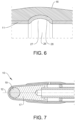
- FIGURES 1-7 An exemplary embodiment of the present invention is shown in FIGURES 1-7 disclosing a dual-direction piston-based actuator housing assembly 10.
- a hollow cylindrical liner 11 extends along a longitudinal axis 12 defining a proximal end 13 opposite a distal end 14.
- the liner may be made from graphite, molydenum disulfide filled polymer, fluoropolymer, PEEK, polymers, neat polymers, neat polymers with solid internal lubricant, CFRP (composite) or even metal.
- a housing 16 is disposed over the liner also extending along the longitudinal axis from the proximal end to the distal end of the liner 11.
- the housing 16 may be made from a continuous fiber reinforced plastic composite, where the continuous fiber reinforced plastic composite of the housing comprises a plurality of continuous fibers wrapped about the longitudinal axis.
- the liner and the housing may be made from a same base resin, as this reduces any mismatches due to differing thermal expansion coefficients.
- the housing may be melt-bonded to the liner.
- a compression block 17 is disposed adjacent to the proximal end of the liner.
- An engagement hole 18 is formed in the compression block configured to accept a pin 19 for attachment when in use as is best shown in FIG. 7 .
- the compression block may be made from a chopped fiber filled thermoplastic composite as its loading is mostly in compression due to the design of the present invention.
- a tension strap 20 is disposed over the compression block.
- the tension strap starts from a first end 21 near the proximal end of the liner and extends around the engagement hole and back to a second end 22 also near the proximal end of the liner.
- the first end and second end are opposite one another disposed approximately 180 degrees apart about the longitudinal axis.
- the tension strap may be made from a continuous fiber reinforced plastic composite.
- the continuous fiber reinforced plastic composite of the tension strap may comprise a plurality of continuous fibers starting from the first end, extending around the engagement hole of the compression block and extending to the second end.
- the tension strap 20 could also extend onto the housing 16.
- the tension strap may be wedge-shaped in a circumferential or a radial direction at the first and second ends, as this helps secure the tension strap in position once the overwind is later applied as discussed below.
- the tension strap may not comprise co-curing elements as was done in the prior art.
- the tension strap and the compression block may comprise a same resin base, as this reduces any mismatches due to differing thermal expansion coefficients.
- An overwind 24 extends at least over the first and second ends of the tension strap, at least partially over the compression block, and at least partially over the proximal end of the housing.
- the overwind secures the tension strap to the compression block while also securing the tension strap and compression block to the housing and liner.
- the overwind may be made from a continuous fiber reinforced plastic composite, where the continuous fiber reinforced plastic composite of the overwind comprises a plurality of continuous fibers wrapped about the longitudinal axis.
- a tension clip 26 is disposed at the distal end of the liner and embedded within the housing.
- the tension clip has a recess 27 formed on an inside surface 28 of the tension clip.
- the recess is annularly disposed about the longitudinal axis.
- the tension clip may be made from a metal, such as aluminum, titanium or steel.
- the liner is configured to accept a movable piston 15 disposed therein.
- An axial support 30 keeps the piston aligned in relation to the liner.
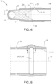
- the axial support 30 is supported in a recess 31 (See FIG. 4 ) of the compression block 17.
- pressure is created on both sides of the piston through a variety of ports.
- a proximally disposed port 23 See FIG. 4
- a distally disposed port 25 See FIG. 5
- a multitude of ports could be used rather than just a single port on each side of the movable piston 15.
- the dual-direction piston-based actuator housing assembly 10 is generally made up of cylindrical parts, such that the parts are circular in cross section.
- the cross sections are oval, triangular, square, rectangular or polygonal such as pentagons, hexagons, octagons and the like.
- FIGURE 8 is an enlarged view similar to FIG. 5 now showing additional parts disposed therein.
- the piston 15 has a multitude of dynamic seals 34, shown herein as o-rings, which create a pressurized seal between the piston 15 and the hollow cylindrical liner 11 or the axial support (i.e. balance tube) 30.
- the seals 34 are dynamic in that movement occurs relative to the seals when the piston 15 moves relative to the liner and the axial support.
- a gland 33 which has a static seal 35 on one side and then a dynamic seal 34 on the other side.
- the static seal 35 is static in that it does not have any movement relative to its use and structural position.
- the dynamic seals 34 of the gland 33 see movement as the piston moves thereby. It will be understood by those skilled in the art that any number of static and/or dynamic seals could be used with the present invention as the invention is not to be limited to the precise forms shown and taught herein.
- the gland 33 is locked into place by a retaining clip 32 which engages both the gland and the tension clip 26. In this manner, the gland is locked into position such that it cannot move within or relative to the liner 11 and housing 16. It is also understood that the retaining clip 32 may be introduced (or removed) into its position from a side hole (not shown) through the housing and liner.
Landscapes
- Engineering & Computer Science (AREA)
- General Engineering & Computer Science (AREA)
- Mechanical Engineering (AREA)
- Physics & Mathematics (AREA)
- Fluid Mechanics (AREA)
- Chemical & Material Sciences (AREA)
- Combustion & Propulsion (AREA)
- Manufacturing & Machinery (AREA)
- Actuator (AREA)
- Pistons, Piston Rings, And Cylinders (AREA)
Claims (15)
- Bidirektionale kolbenbasierte Aktuatorgehäuseanordnung (10), umfassend:- eine hohle zylindrische Buchse (11), die sich entlang einer Längsachse (12) erstreckt und ein proximales Ende (13) gegenüber einem distalen Ende (14) definiert, wobei die Buchse (11) so ausgebildet ist, dass sie einen darin angeordneten, beweglichen Kolben (15) aufnimmt;- ein Gehäuse (16), das über der Buchse (11) angeordnet ist und sich auch entlang der Längsachse (12) von dem proximalen Ende (13) zu dem distalen Ende (14) erstreckt;- einen Kompressionsblock (17), der angrenzend an das proximale Ende (13) der Buchse (11) angeordnet ist;- ein in dem Kompressionsblock (17) gebildetes Eingriffsloch (18), das so ausgebildet ist, dass es einen Stift (19) zur Befestigung bei Gebrauch aufnimmt;- einen Spanngurt (20), der über dem Kompressionsblock (17) angeordnet ist, wobei der Spanngurt (20) sich beginnend von einem ersten Ende (21) nahe des proximalen Endes (13) der Buchse (11) um das Eingriffsloch (18) herum und zurück zu einem zweiten Ende (22) nahe des proximalen Endes (13) der Buchse (11) erstreckt, wobei das erste Ende (21) und das zweite Ende (22) einander gegenüberliegend um 180° voneinander beabstandet um die Längsachse (12) angeordnet sind;- eine Überwicklung (24), die sich zumindest über das erste und das zweite Ende (21, 22) des Spanngurts (20), zumindest teilweise über den Kompressionsblock (17) und zumindest teilweise über das proximale Ende des Gehäuses (16) erstreckt; und- eine Spannklemme (26), die an dem distalen Ende (14) der Buchse (11) angeordnet ist und in dem Gehäuse (16) eingebettet ist, wobei die Spannklemme (26) eine Aussparung (27) hat, die an einer Innenfläche (28) der Spannklemme (26) gebildet ist, wobei die Aussparung (27) ringförmig um die Längsachse (12) angeordnet ist.
- Aktuatorgehäuseanordnung (10) nach Anspruch 1, dadurch gekennzeichnet, dass der Spanngurt (20) einen endlosfaserverstärkten Kunststoffverbundwerkstoff umfasst.
- Aktuatorgehäuseanordnung (10) nach Anspruch 2, dadurch gekennzeichnet, dass der endlosfaserverstärkte Kunststoffverbundwerkstoff des Spanngurts (20) eine Vielzahl von Endlosfasern umfasst, die sich beginnend von dem ersten Ende (21) um das Eingriffsloch (18) des Kompressionsblocks (17) herum und zu dem zweiten Ende (22) erstrecken, wobei vorzugsweise der Spanngurt (20) in einer Umfangsrichtung oder radialen Richtung an dem ersten und dem zweiten Ende (21, 22) keilförmig ist.
- Aktuatorgehäuseanordnung (10) nach Anspruch 2, dadurch gekennzeichnet, dass der Spanngurt (20) keine gleichzeitig härtenden Elemente umfasst.
- Aktuatorgehäuseanordnung (10) nach Anspruch 1, dadurch gekennzeichnet, dass der Kompressionsblock (17) einen mit geschnittenen Fasern gefüllten thermoplastischen Verbundwerkstoff umfasst.
- Aktuatorgehäuseanordnung nach Anspruch 1, dadurch gekennzeichnet, dass der Spanngurt (20) und der Kompressionsblock (17) dasselbe Basisharz umfassen.
- Aktuatorgehäuseanordnung (10) nach Anspruch 1, dadurch gekennzeichnet, dass die Buchse (11) Graphit, ein mit Molybdendisulfid gefülltes Polymer, Fluorpolymer oder PEEK umfasst.
- Aktuatorgehäuseanordnung (10) nach Anspruch 1, dadurch gekennzeichnet, dass die Buchse (11) und das Gehäuse (16) dasselbe Basisharz umfassen.
- Aktuatorgehäuseanordnung (10) nach Anspruch 1, dadurch gekennzeichnet, dass das Gehäuse (16) mit der Buchse (11) schmelzverbunden ist.
- Aktuatorgehäuseanordnung (10) nach Anspruch 1, dadurch gekennzeichnet, dass die Überwicklung (24) einen endlosfaserverstärkten Kunststoffverbundwerkstoff umfasst, der vorzugsweise eine Vielzahl von Endlosfasern aufweist, die um die Längsachse (12) gewickelt sind.
- Aktuatorgehäuseanordnung (10) nach Anspruch 1, dadurch gekennzeichnet, dass das Gehäuse (16) einen endlosfaserverstärkten dadurch gekennzeichnet, umfasst, der vorzugsweise eine Vielzahl von Endlosfasern aufweist, die um die Längsachse (12) gewickelt sind.
- Aktuatorgehäuseanordnung (10) nach Anspruch 1, dadurch gekennzeichnet, dass die Spannklemme (26) ein Metall umfasst.
- Aktuatorgehäuseanordnung (10) nach Anspruch 1,wobei das Gehäuse (16) einen endlosfaserverstärkten Kunststoffverbundwerkstoff umfasst, wobei der endlosfaserverstärkte Kunststoffverbundwerkstoff des Gehäuses (16) eine Vielzahl von Endlosfasern aufweist, die um die Längsachse (12) gewickelt sind;wobei der Kompressionsblock (17) einen mit geschnittenen Fasern gefüllten thermoplastischen Verbundwerkstoff umfasst;wobei der Spanngurt (20) einen endlosfaserverstärkten Kunststoffverbundwerkstoff umfasst, wobei der endlosfaserverstärkte Kunststoffverbundwerkstoff des Spanngurts (20) eine Vielzahl von Endlosfasern aufweist, die sich beginnend von dem ersten Ende (21) um das Eingriffsloch (18) des Kompressionsblocks (17) herum zu dem zweiten Ende (22) erstrecken; undwobei die Überwicklung (24) einen endlosfaserverstärkten Kunststoffverbundwerkstoff umfasst, wobei der endlosfaserverstärkte Kunststoffverbundwerkstoff der Überwicklung (24) eine Vielzahl von Endlosfasern aufweist, die um die Längsachse (12) gewickelt sind.
- Aktuatorgehäuseanordnung (10) nach Anspruch 13, dadurch gekennzeichnet, dass die Buchse (11) und das Gehäuse (16) dasselbe erste Basisharz umfassen, wobei der Spanngurt (20) und der Kompressionsblock (17) vorzugsweise dasselbe zweite Basisharz umfassen.
- Aktuatorgehäuseanordnung (10) nach Anspruch 13,wobei die Buchse (11) und das Gehäuse (16) dasselbe erste Basisharz umfassen;wobei der Spanngurt (20) und der Kompressionsblock (17) dasselbe zweite Basisharz umfassen;und wobei die Spannklemme (26) ein Metall umfasst.
Applications Claiming Priority (2)
| Application Number | Priority Date | Filing Date | Title |
|---|---|---|---|
| US17/647,437 US11493063B1 (en) | 2022-01-07 | 2022-01-07 | Lightweight composite actuator |
| PCT/EP2022/087014 WO2023131520A1 (en) | 2022-01-07 | 2022-12-20 | Lightweight composite actuator |
Publications (3)
| Publication Number | Publication Date |
|---|---|
| EP4402379A1 EP4402379A1 (de) | 2024-07-24 |
| EP4402379B1 true EP4402379B1 (de) | 2025-01-29 |
| EP4402379C0 EP4402379C0 (de) | 2025-01-29 |
Family
ID=83902585
Family Applications (1)
| Application Number | Title | Priority Date | Filing Date |
|---|---|---|---|
| EP22840180.8A Active EP4402379B1 (de) | 2022-01-07 | 2022-12-20 | Leichtgewicht-kompositaktuator |
Country Status (4)
| Country | Link |
|---|---|
| US (1) | US11493063B1 (de) |
| EP (1) | EP4402379B1 (de) |
| CN (1) | CN118401757B (de) |
| WO (1) | WO2023131520A1 (de) |
Families Citing this family (1)
| Publication number | Priority date | Publication date | Assignee | Title |
|---|---|---|---|---|
| US12180837B1 (en) * | 2023-08-28 | 2024-12-31 | Goodrich Corporation | Composite actuator systems and methods of making the same |
Family Cites Families (32)
| Publication number | Priority date | Publication date | Assignee | Title |
|---|---|---|---|---|
| JPS55159310A (en) * | 1979-05-29 | 1980-12-11 | Celanese Corp | Fiberrreinforced composit shaft with metallic connector sleeve fitted by mechanical interlock |
| US4685384A (en) | 1984-08-20 | 1987-08-11 | Pneumo Corporation | Fluid actuator including composite cylinder assembly |
| CA1251379A (en) * | 1984-08-20 | 1989-03-21 | William Dirkin | Fluid actuator including composite cylinder assembly |
| US4777869A (en) | 1986-03-28 | 1988-10-18 | Pneumo Abex Corporation | Fluid actuator including a composite piston rod |
| US4872370A (en) | 1987-04-06 | 1989-10-10 | Pneumo Abex Corporation | Piston rod assembly including preloaded piston head and composite rod |
| US4773282A (en) | 1987-04-06 | 1988-09-27 | Pneumo Abex Corporation | Piston rod assembly including an injection bonded piston head and fabrication method |
| US4802404A (en) | 1987-04-06 | 1989-02-07 | Pneumo Abex Corporation | Composite cylinder assembly with removable liner assembly |
| US4971846A (en) | 1987-11-16 | 1990-11-20 | Tre Corporation | Thermoplastic cylinder and process for manufacturing same |
| US5101556A (en) | 1990-12-17 | 1992-04-07 | Allied-Signal Inc. | Method of manufacturing a piston |
| US5154109A (en) | 1990-12-17 | 1992-10-13 | Allied-Signal Inc. | Composite piston assembly |
| US5415079A (en) | 1992-05-13 | 1995-05-16 | Hr Textron, Inc. | Composite cylinder for use in aircraft hydraulic actuator |
| EA006268B1 (ru) | 1999-04-22 | 2005-10-27 | Нвб Интернэшнл | Устройство, содержащее комбинацию камеры и поршня |
| US20020170426A1 (en) | 2001-05-16 | 2002-11-21 | Braatz James D. | Pneumatic cylinder for railroad track switch operator |
| DE10138322B4 (de) | 2001-08-10 | 2004-01-29 | Deutsches Zentrum für Luft- und Raumfahrt e.V. | Kolbenstangenanordnung |
| US20030226635A1 (en) | 2002-06-07 | 2003-12-11 | Fish Elson B. | Aeroslide bearing cylinder |
| DE102004008523B4 (de) * | 2004-02-20 | 2007-02-01 | Liebherr-Aerospace Lindenberg Gmbh | Verfahren zur Herstellung eines Druckzylinders und Kolbenstange für Aktuatoren oder Stoßdämpfer und Verfahren zu deren Herstellung |
| US20060016329A1 (en) | 2004-07-26 | 2006-01-26 | S.A. Robotics | Composite fluid actuated cylinder |
| US7617874B2 (en) | 2006-09-11 | 2009-11-17 | Schlumberger Technology Corporation | Flexible matrix composite actuator for use in subsurface wellbores |
| DE102006062414A1 (de) * | 2006-12-22 | 2008-06-26 | Technische Universität Dresden | Zylinderrohr für einen Hydraulikzylinder aus Faserverbundwerkstoff und Verfahren zu dessen Herstellung |
| US20090255400A1 (en) | 2008-04-14 | 2009-10-15 | Polygon Company | Hybrid Piston Rod |
| US8991299B2 (en) | 2011-07-06 | 2015-03-31 | Hamilton Sundstrand Corporation | Reinforced thermoplastic actuator with wear resistant plastic liner |
| DE102011087597A1 (de) * | 2011-12-01 | 2013-06-06 | Bayerische Motoren Werke Aktiengesellschaft | Leichtbau-Teleskop-Schwingungsdämpfer |
| US9611935B2 (en) | 2012-11-12 | 2017-04-04 | Ge Oil & Gas Compression Systems, Llc | Light composite piston |
| AT514081B1 (de) | 2013-03-28 | 2014-10-15 | Mark Hydraulik Gmbh | Zylindergehäuse in Leichtbau-Mischbauweise sowie Verfahren zur Herstellung desselben |
| US10295059B2 (en) | 2014-06-13 | 2019-05-21 | Cifa S.P.A. | Cylinder made of composite material for an actuator and corresponding method of production |
| US10190607B2 (en) | 2015-01-30 | 2019-01-29 | Goodrich Corporation | Composite actuator piston head assembly |
| US9873506B2 (en) | 2015-03-20 | 2018-01-23 | Goodrich Corporation | Composite actuator rod end assembly |
| EP3133298B1 (de) | 2015-08-21 | 2019-02-06 | Crompton Technology Group Limited | Verbinder |
| US10066649B2 (en) | 2015-10-13 | 2018-09-04 | Goodrich Corporation | Hybrid metallic/composite piston head joint |
| US20200018383A1 (en) * | 2018-07-13 | 2020-01-16 | Borgwarner Inc. | Hydraulic tensioner with moving sleeve |
| US11085465B2 (en) | 2019-03-11 | 2021-08-10 | Goodrich Corporation | Retention systems for light weight actuator glands |
| WO2021060603A1 (ko) | 2019-09-25 | 2021-04-01 | (주)에스에이치팩 | 유압 실린더 로드 |
-
2022
- 2022-01-07 US US17/647,437 patent/US11493063B1/en active Active
- 2022-12-20 CN CN202280078819.2A patent/CN118401757B/zh active Active
- 2022-12-20 WO PCT/EP2022/087014 patent/WO2023131520A1/en not_active Ceased
- 2022-12-20 EP EP22840180.8A patent/EP4402379B1/de active Active
Also Published As
| Publication number | Publication date |
|---|---|
| CN118401757A (zh) | 2024-07-26 |
| CN118401757B (zh) | 2025-03-07 |
| EP4402379A1 (de) | 2024-07-24 |
| US11493063B1 (en) | 2022-11-08 |
| EP4402379C0 (de) | 2025-01-29 |
| WO2023131520A1 (en) | 2023-07-13 |
Similar Documents
| Publication | Publication Date | Title |
|---|---|---|
| US20240060582A1 (en) | Composite connectors and methods of manufacturing the same | |
| US20230160505A1 (en) | Composite connectors and methods of manufacturing the same | |
| EP3719375B1 (de) | Verbundverbinder und verfahren zur herstellung davon | |
| EP0239406B1 (de) | Arbeitszylinder mit einer Kolbenstange aus Verbundmaterial | |
| EP3819507B1 (de) | Welle aus verstärkten kunststoff mit einem anschlussstück | |
| US3731367A (en) | Method of assemblying compound body | |
| EP4402379B1 (de) | Leichtgewicht-kompositaktuator | |
| EP3608089B1 (de) | Verbundverbinder und verfahren zur herstellung davon | |
| JP2022546613A (ja) | テンション-コンプレッションロッドのためのポジティブ・ロック式の荷重負荷を引き起こすための方法、およびテンション-コンプレッションロッド | |
| EP0564455B1 (de) | Verfahren zum herstellen eines kolbens sowie ein stellantrieb mit einem kolben | |
| US20060016329A1 (en) | Composite fluid actuated cylinder | |
| US5154109A (en) | Composite piston assembly | |
| JPH03236946A (ja) | 繊維強化樹脂製シリンダチューブの製造法 | |
| EP3798137B1 (de) | Rohrstruktur und künstlicher satellit, der diese verwendet | |
| US4807531A (en) | Contemporary composite polar boss | |
| EP0176212A1 (de) | Arbeitszylinder mit Verbundzylinderrohr | |
| US12180837B1 (en) | Composite actuator systems and methods of making the same | |
| JP3723849B2 (ja) | アクチュエータ | |
| EP4241968B1 (de) | Verbundmetallverbindungen für verbundstäbe | |
| Maass | Tubular Composite Compression Members-Design Considerations and Practices | |
| WO2014091514A1 (en) | Innovative connecting rod in composite material | |
| JPH0434267A (ja) | ピストンピンの製造方法 |
Legal Events
| Date | Code | Title | Description |
|---|---|---|---|
| STAA | Information on the status of an ep patent application or granted ep patent |
Free format text: STATUS: UNKNOWN |
|
| STAA | Information on the status of an ep patent application or granted ep patent |
Free format text: STATUS: THE INTERNATIONAL PUBLICATION HAS BEEN MADE |
|
| PUAI | Public reference made under article 153(3) epc to a published international application that has entered the european phase |
Free format text: ORIGINAL CODE: 0009012 |
|
| STAA | Information on the status of an ep patent application or granted ep patent |
Free format text: STATUS: REQUEST FOR EXAMINATION WAS MADE |
|
| 17P | Request for examination filed |
Effective date: 20240418 |
|
| AK | Designated contracting states |
Kind code of ref document: A1 Designated state(s): AL AT BE BG CH CY CZ DE DK EE ES FI FR GB GR HR HU IE IS IT LI LT LU LV MC ME MK MT NL NO PL PT RO RS SE SI SK SM TR |
|
| GRAP | Despatch of communication of intention to grant a patent |
Free format text: ORIGINAL CODE: EPIDOSNIGR1 |
|
| STAA | Information on the status of an ep patent application or granted ep patent |
Free format text: STATUS: GRANT OF PATENT IS INTENDED |
|
| INTG | Intention to grant announced |
Effective date: 20240916 |
|
| RIN1 | Information on inventor provided before grant (corrected) |
Inventor name: PASANEN, MICHAEL JAMES Inventor name: KIMBALL, BRETT ARNOLD |
|
| GRAS | Grant fee paid |
Free format text: ORIGINAL CODE: EPIDOSNIGR3 |
|
| GRAA | (expected) grant |
Free format text: ORIGINAL CODE: 0009210 |
|
| STAA | Information on the status of an ep patent application or granted ep patent |
Free format text: STATUS: THE PATENT HAS BEEN GRANTED |
|
| P01 | Opt-out of the competence of the unified patent court (upc) registered |
Free format text: CASE NUMBER: APP_65698/2024 Effective date: 20241212 |
|
| AK | Designated contracting states |
Kind code of ref document: B1 Designated state(s): AL AT BE BG CH CY CZ DE DK EE ES FI FR GB GR HR HU IE IS IT LI LT LU LV MC ME MK MT NL NO PL PT RO RS SE SI SK SM TR |
|
| DAV | Request for validation of the european patent (deleted) | ||
| DAX | Request for extension of the european patent (deleted) | ||
| REG | Reference to a national code |
Ref country code: GB Ref legal event code: FG4D |
|
| REG | Reference to a national code |
Ref country code: CH Ref legal event code: EP |
|
| REG | Reference to a national code |
Ref country code: DE Ref legal event code: R096 Ref document number: 602022010301 Country of ref document: DE |
|
| REG | Reference to a national code |
Ref country code: IE Ref legal event code: FG4D |
|
| U01 | Request for unitary effect filed |
Effective date: 20250130 |
|
| P04 | Withdrawal of opt-out of the competence of the unified patent court (upc) registered |
Free format text: CASE NUMBER: APP_5775/2025 Effective date: 20250204 |
|
| U07 | Unitary effect registered |
Designated state(s): AT BE BG DE DK EE FI FR IT LT LU LV MT NL PT RO SE SI Effective date: 20250206 |
|
| PG25 | Lapsed in a contracting state [announced via postgrant information from national office to epo] |
Ref country code: RS Free format text: LAPSE BECAUSE OF FAILURE TO SUBMIT A TRANSLATION OF THE DESCRIPTION OR TO PAY THE FEE WITHIN THE PRESCRIBED TIME-LIMIT Effective date: 20250429 |
|
| PG25 | Lapsed in a contracting state [announced via postgrant information from national office to epo] |
Ref country code: PL Free format text: LAPSE BECAUSE OF FAILURE TO SUBMIT A TRANSLATION OF THE DESCRIPTION OR TO PAY THE FEE WITHIN THE PRESCRIBED TIME-LIMIT Effective date: 20250129 |
|
| PG25 | Lapsed in a contracting state [announced via postgrant information from national office to epo] |
Ref country code: ES Free format text: LAPSE BECAUSE OF FAILURE TO SUBMIT A TRANSLATION OF THE DESCRIPTION OR TO PAY THE FEE WITHIN THE PRESCRIBED TIME-LIMIT Effective date: 20250129 |
|
| PG25 | Lapsed in a contracting state [announced via postgrant information from national office to epo] |
Ref country code: NO Free format text: LAPSE BECAUSE OF FAILURE TO SUBMIT A TRANSLATION OF THE DESCRIPTION OR TO PAY THE FEE WITHIN THE PRESCRIBED TIME-LIMIT Effective date: 20250429 Ref country code: IS Free format text: LAPSE BECAUSE OF FAILURE TO SUBMIT A TRANSLATION OF THE DESCRIPTION OR TO PAY THE FEE WITHIN THE PRESCRIBED TIME-LIMIT Effective date: 20250529 |
|
| PG25 | Lapsed in a contracting state [announced via postgrant information from national office to epo] |
Ref country code: HR Free format text: LAPSE BECAUSE OF FAILURE TO SUBMIT A TRANSLATION OF THE DESCRIPTION OR TO PAY THE FEE WITHIN THE PRESCRIBED TIME-LIMIT Effective date: 20250129 |
|
| PG25 | Lapsed in a contracting state [announced via postgrant information from national office to epo] |
Ref country code: GR Free format text: LAPSE BECAUSE OF FAILURE TO SUBMIT A TRANSLATION OF THE DESCRIPTION OR TO PAY THE FEE WITHIN THE PRESCRIBED TIME-LIMIT Effective date: 20250430 |
|
| PG25 | Lapsed in a contracting state [announced via postgrant information from national office to epo] |
Ref country code: SM Free format text: LAPSE BECAUSE OF FAILURE TO SUBMIT A TRANSLATION OF THE DESCRIPTION OR TO PAY THE FEE WITHIN THE PRESCRIBED TIME-LIMIT Effective date: 20250129 |
|
| PG25 | Lapsed in a contracting state [announced via postgrant information from national office to epo] |
Ref country code: CZ Free format text: LAPSE BECAUSE OF FAILURE TO SUBMIT A TRANSLATION OF THE DESCRIPTION OR TO PAY THE FEE WITHIN THE PRESCRIBED TIME-LIMIT Effective date: 20250129 |
|
| PG25 | Lapsed in a contracting state [announced via postgrant information from national office to epo] |
Ref country code: SK Free format text: LAPSE BECAUSE OF FAILURE TO SUBMIT A TRANSLATION OF THE DESCRIPTION OR TO PAY THE FEE WITHIN THE PRESCRIBED TIME-LIMIT Effective date: 20250129 |
|
| PLBE | No opposition filed within time limit |
Free format text: ORIGINAL CODE: 0009261 |
|
| STAA | Information on the status of an ep patent application or granted ep patent |
Free format text: STATUS: NO OPPOSITION FILED WITHIN TIME LIMIT |
|
| 26N | No opposition filed |
Effective date: 20251030 |
|
| U20 | Renewal fee for the european patent with unitary effect paid |
Year of fee payment: 4 Effective date: 20251217 |