EP4401460A1 - Verfahren und vorrichtung zur pdcch-überwachung - Google Patents
Verfahren und vorrichtung zur pdcch-überwachung Download PDFInfo
- Publication number
- EP4401460A1 EP4401460A1 EP22880129.6A EP22880129A EP4401460A1 EP 4401460 A1 EP4401460 A1 EP 4401460A1 EP 22880129 A EP22880129 A EP 22880129A EP 4401460 A1 EP4401460 A1 EP 4401460A1
- Authority
- EP
- European Patent Office
- Prior art keywords
- time
- time windows
- drx
- configuration information
- time window
- Prior art date
- Legal status (The legal status is an assumption and is not a legal conclusion. Google has not performed a legal analysis and makes no representation as to the accuracy of the status listed.)
- Pending
Links
- 238000000034 method Methods 0.000 title claims abstract description 135
- 238000012544 monitoring process Methods 0.000 title claims abstract description 76
- 238000004891 communication Methods 0.000 claims abstract description 71
- 230000006854 communication Effects 0.000 claims abstract description 71
- 230000000694 effects Effects 0.000 claims description 43
- 238000012545 processing Methods 0.000 claims description 31
- 238000004590 computer program Methods 0.000 claims description 14
- 238000005516 engineering process Methods 0.000 abstract description 5
- 238000013461 design Methods 0.000 description 84
- 230000006870 function Effects 0.000 description 56
- 238000010586 diagram Methods 0.000 description 32
- 206010062519 Poor quality sleep Diseases 0.000 description 29
- 230000009467 reduction Effects 0.000 description 27
- 230000005540 biological transmission Effects 0.000 description 18
- 238000001228 spectrum Methods 0.000 description 9
- 230000011664 signaling Effects 0.000 description 7
- 230000003993 interaction Effects 0.000 description 6
- 230000008569 process Effects 0.000 description 6
- 238000010295 mobile communication Methods 0.000 description 5
- 230000001934 delay Effects 0.000 description 4
- 230000007246 mechanism Effects 0.000 description 4
- 230000003190 augmentative effect Effects 0.000 description 3
- 230000009286 beneficial effect Effects 0.000 description 3
- 230000006978 adaptation Effects 0.000 description 2
- 239000011521 glass Substances 0.000 description 2
- 102100022734 Acyl carrier protein, mitochondrial Human genes 0.000 description 1
- 101000678845 Homo sapiens Acyl carrier protein, mitochondrial Proteins 0.000 description 1
- 230000007175 bidirectional communication Effects 0.000 description 1
- 230000008859 change Effects 0.000 description 1
- 238000013500 data storage Methods 0.000 description 1
- 230000003111 delayed effect Effects 0.000 description 1
- 238000011161 development Methods 0.000 description 1
- 230000004069 differentiation Effects 0.000 description 1
- 239000000446 fuel Substances 0.000 description 1
- 230000003287 optical effect Effects 0.000 description 1
- 230000004044 response Effects 0.000 description 1
- 239000004065 semiconductor Substances 0.000 description 1
- 239000004984 smart glass Substances 0.000 description 1
- XLYOFNOQVPJJNP-UHFFFAOYSA-N water Substances O XLYOFNOQVPJJNP-UHFFFAOYSA-N 0.000 description 1
Images


Classifications
-
- H—ELECTRICITY
- H04—ELECTRIC COMMUNICATION TECHNIQUE
- H04W—WIRELESS COMMUNICATION NETWORKS
- H04W72/00—Local resource management
- H04W72/12—Wireless traffic scheduling
- H04W72/1263—Mapping of traffic onto schedule, e.g. scheduled allocation or multiplexing of flows
- H04W72/1273—Mapping of traffic onto schedule, e.g. scheduled allocation or multiplexing of flows of downlink data flows
-
- H—ELECTRICITY
- H04—ELECTRIC COMMUNICATION TECHNIQUE
- H04L—TRANSMISSION OF DIGITAL INFORMATION, e.g. TELEGRAPHIC COMMUNICATION
- H04L1/00—Arrangements for detecting or preventing errors in the information received
- H04L1/12—Arrangements for detecting or preventing errors in the information received by using return channel
- H04L1/16—Arrangements for detecting or preventing errors in the information received by using return channel in which the return channel carries supervisory signals, e.g. repetition request signals
- H04L1/1607—Details of the supervisory signal
- H04L1/1614—Details of the supervisory signal using bitmaps
-
- H—ELECTRICITY
- H04—ELECTRIC COMMUNICATION TECHNIQUE
- H04W—WIRELESS COMMUNICATION NETWORKS
- H04W24/00—Supervisory, monitoring or testing arrangements
- H04W24/08—Testing, supervising or monitoring using real traffic
-
- H—ELECTRICITY
- H04—ELECTRIC COMMUNICATION TECHNIQUE
- H04W—WIRELESS COMMUNICATION NETWORKS
- H04W48/00—Access restriction; Network selection; Access point selection
- H04W48/08—Access restriction or access information delivery, e.g. discovery data delivery
- H04W48/12—Access restriction or access information delivery, e.g. discovery data delivery using downlink control channel
-
- H—ELECTRICITY
- H04—ELECTRIC COMMUNICATION TECHNIQUE
- H04W—WIRELESS COMMUNICATION NETWORKS
- H04W52/00—Power management, e.g. Transmission Power Control [TPC] or power classes
- H04W52/02—Power saving arrangements
-
- H—ELECTRICITY
- H04—ELECTRIC COMMUNICATION TECHNIQUE
- H04W—WIRELESS COMMUNICATION NETWORKS
- H04W52/00—Power management, e.g. Transmission Power Control [TPC] or power classes
- H04W52/02—Power saving arrangements
- H04W52/0209—Power saving arrangements in terminal devices
- H04W52/0212—Power saving arrangements in terminal devices managed by the network, e.g. network or access point is leader and terminal is follower
- H04W52/0216—Power saving arrangements in terminal devices managed by the network, e.g. network or access point is leader and terminal is follower using a pre-established activity schedule, e.g. traffic indication frame
-
- H—ELECTRICITY
- H04—ELECTRIC COMMUNICATION TECHNIQUE
- H04W—WIRELESS COMMUNICATION NETWORKS
- H04W52/00—Power management, e.g. Transmission Power Control [TPC] or power classes
- H04W52/02—Power saving arrangements
- H04W52/0209—Power saving arrangements in terminal devices
- H04W52/0225—Power saving arrangements in terminal devices using monitoring of external events, e.g. the presence of a signal
- H04W52/0229—Power saving arrangements in terminal devices using monitoring of external events, e.g. the presence of a signal where the received signal is a wanted signal
-
- H—ELECTRICITY
- H04—ELECTRIC COMMUNICATION TECHNIQUE
- H04W—WIRELESS COMMUNICATION NETWORKS
- H04W72/00—Local resource management
- H04W72/04—Wireless resource allocation
- H04W72/044—Wireless resource allocation based on the type of the allocated resource
- H04W72/0446—Resources in time domain, e.g. slots or frames
-
- H—ELECTRICITY
- H04—ELECTRIC COMMUNICATION TECHNIQUE
- H04W—WIRELESS COMMUNICATION NETWORKS
- H04W76/00—Connection management
- H04W76/20—Manipulation of established connections
- H04W76/28—Discontinuous transmission [DTX]; Discontinuous reception [DRX]
-
- Y—GENERAL TAGGING OF NEW TECHNOLOGICAL DEVELOPMENTS; GENERAL TAGGING OF CROSS-SECTIONAL TECHNOLOGIES SPANNING OVER SEVERAL SECTIONS OF THE IPC; TECHNICAL SUBJECTS COVERED BY FORMER USPC CROSS-REFERENCE ART COLLECTIONS [XRACs] AND DIGESTS
- Y02—TECHNOLOGIES OR APPLICATIONS FOR MITIGATION OR ADAPTATION AGAINST CLIMATE CHANGE
- Y02D—CLIMATE CHANGE MITIGATION TECHNOLOGIES IN INFORMATION AND COMMUNICATION TECHNOLOGIES [ICT], I.E. INFORMATION AND COMMUNICATION TECHNOLOGIES AIMING AT THE REDUCTION OF THEIR OWN ENERGY USE
- Y02D30/00—Reducing energy consumption in communication networks
- Y02D30/70—Reducing energy consumption in communication networks in wireless communication networks
Definitions
- Embodiments of this application relate to the field of communication technologies, and in particular, to a physical downlink control channel (physical downlink control channel, PDCCH) monitoring method and apparatus.
- PDCCH physical downlink control channel
- a discontinuous reception (discontinuous reception, DRX) technology is introduced for power saving (power saving).
- a basic mechanism of DRX is to configure a DRX cycle (cycle) for a terminal device.
- a terminal device in one DRX cycle, in a DRX on duration (on duration), a terminal device normally monitors a PDCCH; and in another time period, the terminal device has an opportunity (opportunity) to enter a sleep state, and does not receive a PDCCH, to reduce power consumption.
- jitter occurs at an arrival moment of a service frame, that is, an arrival moment of the service frame is earlier or later than a specific ideal arrival moment.
- duration of a DRX on duration needs to be set to cover a time range that may be reached by the entire service frame. Consequently, time for monitoring a PDCCH by the terminal device is excessively long, and power consumption is excessively high.
- Embodiments of this application provide a communication method and apparatus, to reduce power consumption of a terminal device.
- an embodiment of this application provides a communication method.
- the method may be performed by a terminal device, or may be performed by a component (for example, a processor, a chip, or a chip system) of the terminal device, or may be implemented by a logical module or software that can implement all or some functions of the terminal device.
- the method includes: receiving configuration information from a network device; and monitoring a PDCCH in M1 first time windows in N1 first time windows of a first time period based on the configuration information, where the first time period is a DRX on duration, N1 is an integer greater than or equal to 2, and M1 is a positive integer less than N1.
- the DRX on duration is divided into a plurality of (two or more) first time windows, so that the terminal device monitors the PDCCH in some first time windows in the DRX on duration, and can enter sleep in a first time window, in the DRX on duration, in which the PDCCH does not need to be monitored. This reduces power consumption.
- the configuration information includes time window bitmap information, and the time window bitmap information is used to configure the M1 first time windows.
- the configuration information is further used to configure a value of N1 or duration of one of the N1 first time windows.
- the foregoing design provides a flexible implementation in which the network device configures, for the terminal device, the M1 first time windows used to monitor the PDCCH, and therefore helps meet different communication requirements.
- the configuration information includes time window index information, and the time window index information is used to configure the M1 first time windows.
- a first time window pattern corresponding to the M1 first time windows is one of a plurality of first time window patterns.
- information element overheads of configuring, by the network device for the terminal device, the M1 first time windows used to monitor the PDCCH are reduced, so that wireless communication resources can be saved, and utilization of wireless communication resources can be improved.
- the method further includes: sending DRX preference information to the network device, where the DRX preference information indicates a preference for power consumption and/or a preference for a delay.
- the foregoing design helps the network device deliver the configuration information to the terminal device based on the DRX preference information of the terminal device, and therefore obtains a better experience level with as low power consumption as possible while meeting performance requirements of a user on power consumption and a service delay.
- the DRX preference information may indicate the preference for power consumption, for example, a power consumption reduction proportion.
- the network device may deliver, to the terminal device based on a power consumption requirement, of the terminal device, that the power consumption reduction proportion (for example, 20%) is reduced when the first time period is totally used to monitor the PDCCH, the configuration information to configure the M1 first time windows used to monitor the PDCCH, so that the terminal device monitors the PDCCH in the M1 first time windows in the N1 first time windows of the first time period. This meets the power consumption requirement of the terminal device.
- the DRX preference information may indicate the preference for the delay, for example, an average schedule delay.
- the network device may deliver, to the terminal device based on a requirement, of the terminal device, that a delay not longer than the average schedule delay is added on a basis of a schedule delay when the first time period is totally used to monitor the PDCCH, the configuration information to configure the M1 first time windows used to monitor the PDCCH, so that the terminal device monitors the PDCCH in the M1 first time windows in the N1 first time windows of the first time period. This reduces power consumption of the terminal device, and meets the service delay requirement of the terminal device.
- the DRX preference information may alternatively indicate both the preference for power consumption and the preference for the delay, for example, a power consumption reduction proportion and an average schedule delay.
- the network device may deliver, to the terminal device based on a power consumption requirement, of the terminal device, that the power consumption reduction proportion is reduced when the first time period is totally used to monitor the PDCCH and a requirement that a delay not longer than the average schedule delay is added on a basis of a schedule delay when the first time period is totally used to monitor the PDCCH, the configuration information to configure the M1 first time windows used to monitor the PDCCH, so that the terminal device monitors the PDCCH in the M1 first time windows in the N1 first time windows of the first time period. This reduces power consumption of the terminal device, and meets the service delay requirement of the terminal device.
- the method further includes: monitoring the PDCCH in M2 second time windows in N2 second time windows of a second time period based on the configuration information, where the first time period is a DRX on duration of a long DRX cycle, the second time period is a DRX on duration of a short DRX cycle, N2 is an integer greater than or equal to 2, and M2 is a positive integer less than N2.
- the foregoing design can be used to resolve a problem that different types of service frames (for example, video frames) have different delay requirements.
- the M1 first time windows and the M2 second time windows that are used to monitor the PDCCH are configured in the DRX on duration of the long DRX cycle and the DRX on duration of the short DRX cycle respectively. This can better reduce power consumption of the terminal device while meeting the delay requirements of the different types of service frames.
- the method further includes: obtaining M2 second time windows in N2 second time windows of a second time period based on the configuration information, where the first time period is a DRX on duration of a long DRX cycle, the second time period is a DRX on duration of a short DRX cycle, N2 is an integer greater than or equal to 2, and M2 is a positive integer less than N2; and when the first time period and the second time period do not overlap in time, monitoring the PDCCH in the M2 second time windows; and the monitoring a PDCCH in M1 first time windows in N1 first time windows of a first time period includes: when the first time period and the second time period overlap in time, monitoring the PDCCH in the M1 first time windows.
- the foregoing design can be used to resolve a problem that different types of service frames (for example, video frames) have different delay requirements.
- the M1 first time windows and the M2 second time windows that are used to monitor the PDCCH are configured in the DRX on duration of the long DRX cycle and the DRX on duration of the short DRX cycle respectively. This can better reduce power consumption of the terminal device while meeting the delay requirements of the different types of service frames, and further provide a solution for a conflict between the DRX on duration of the long DRX cycle and the DRX on duration of the short DRX cycle.
- an embodiment of this application provides a communication method.
- the method may be performed by a terminal device, or may be performed by a component (for example, a processor, a chip, or a chip system) of the terminal device, or may be implemented by a logical module or software that can implement all or some functions of the terminal device.
- the method includes: receiving configuration information from a network device; and monitoring a PDCCH in M1 first time windows in N1 first time windows of a first time period based on the configuration information, where duration of the first time period is a DRX cycle, N1 is an integer greater than or equal to 3, and M1 is an integer less than N1 and greater than or equal to 2.
- the DRX cycle is divided into a plurality of (two or more) first time windows, so that the terminal device monitors the PDCCH in some first time windows in the DRX cycle, and can enter sleep in a first time window, in the DRX cycle, in which the PDCCH does not need to be monitored. This reduces power consumption.
- the at least two first time windows that are inconsecutive in the time in the M1 first time windows used to monitor the PDCCH, so that the first time windows used to monitor the PDCCH are deployed in a decentralized manner in the DRX cycle. This reduces a service delay as much as possible.
- the configuration information includes time window bitmap information, and the time window bitmap information is used to configure the M1 first time windows.
- the configuration information is further used to configure a value of N1 or duration of one of the N1 first time windows.
- the foregoing design provides a flexible implementation in which the network device configures, for the terminal device, the M1 first time windows used to monitor the PDCCH, and therefore helps meet different communication requirements.
- the configuration information includes time window index information, and the time window index information is used to configure the M1 first time windows.
- a first time window pattern corresponding to the M1 first time windows is one of a plurality of first time window patterns.
- information element overheads of configuring, by the network device for the terminal device, the M1 first time windows used to monitor the PDCCH are reduced, so that wireless communication resources can be saved, and utilization of wireless communication resources can be improved.
- the method further includes: sending DRX preference information to the network device, where the DRX preference information indicates a preference for power consumption and/or a preference for a delay.
- the foregoing design helps the network device deliver the configuration information to the terminal device based on the DRX preference information of the terminal device, and therefore obtains a better experience level with as low power consumption as possible while meeting performance requirements of a user on power consumption and a service delay.
- the DRX preference information may indicate the preference for power consumption, for example, a power consumption reduction proportion.
- the network device may deliver, to the terminal device based on a power consumption requirement, of the terminal device, that the power consumption reduction proportion (for example, 20%) is reduced when the first time period is totally used to monitor the PDCCH, the configuration information to configure the M1 first time windows used to monitor the PDCCH, so that the terminal device monitors the PDCCH in the M1 first time windows in the N1 first time windows of the first time period. This meets the power consumption requirement of the terminal device.
- the DRX preference information may indicate the preference for the delay, for example, an average schedule delay.
- the network device may deliver, to the terminal device based on a requirement, of the terminal device, that a delay not longer than the average schedule delay is added on a basis of a schedule delay when the first time period is totally used to monitor the PDCCH, the configuration information to configure the M1 first time windows used to monitor the PDCCH, so that the terminal device monitors the PDCCH in the M1 first time windows in the N1 first time windows of the first time period. This reduces power consumption of the terminal device, and meets the service delay requirement of the terminal device.
- the DRX preference information may alternatively indicate both the preference for power consumption and the preference for the delay, for example, a power consumption reduction proportion and an average schedule delay.
- the network device may deliver, to the terminal device based on a power consumption requirement, of the terminal device, that the power consumption reduction proportion is reduced when the first time period is totally used to monitor the PDCCH and a requirement that a delay not longer than the average schedule delay is added on a basis of a schedule delay when the first time period is totally used to monitor the PDCCH, the configuration information to configure the M1 first time windows used to monitor the PDCCH, so that the terminal device monitors the PDCCH in the M1 first time windows in the N1 first time windows of the first time period. This reduces power consumption of the terminal device, and meets the service delay requirement of the terminal device.
- an embodiment of this application provides a communication method.
- the method may be performed by a network device, or may be performed by a component (for example, a processor, a chip, or a chip system) of the network device, or may be implemented by a logical module or software that can implement all or some functions of the network device.
- the method includes: generating configuration information, where the configuration information is used to configure M1 first time windows in N1 first time windows of a first time period, the M1 first time windows are used to monitor a PDCCH, the first time period is a DRX on duration, N1 is an integer greater than or equal to 2, and M1 is a positive integer less than N1; and sending the configuration information to a terminal device.
- the configuration information includes time window bitmap information, and the time window bitmap information is used to configure the M1 first time windows.
- the configuration information is further used to configure a value of N1 or duration of one of the N1 first time windows.
- the configuration information includes time window index information, and the time window index information is used to configure the M1 first time windows.
- a first time window pattern corresponding to the M1 first time windows is one of a plurality of first time window patterns.
- the method further includes: receiving DRX preference information from the terminal device, where the DRX preference information indicates a preference for power consumption and/or a preference for a delay.
- the DRX preference information may indicate the preference for power consumption, for example, a power consumption reduction proportion.
- the network device may deliver, to the terminal device based on a power consumption requirement, of the terminal device, that the power consumption reduction proportion (for example, 20%) is reduced when the first time period is totally used to monitor the PDCCH, the configuration information to configure the M1 first time windows used to monitor the PDCCH, so that the terminal device monitors the PDCCH in the M1 first time windows in the N1 first time windows of the first time period. This meets the power consumption requirement of the terminal device.
- the DRX preference information may indicate the preference for the delay, for example, an average schedule delay.
- the network device may deliver, to the terminal device based on a requirement, of the terminal device, that a delay not longer than the average schedule delay is added on a basis of a schedule delay when the first time period is totally used to monitor the PDCCH, the configuration information to configure the M1 first time windows used to monitor the PDCCH, so that the terminal device monitors the PDCCH in the M1 first time windows in the N1 first time windows of the first time period. This reduces power consumption of the terminal device, and meets the service delay requirement of the terminal device.
- the DRX preference information may alternatively indicate both the preference for power consumption and the preference for the delay, for example, a power consumption reduction proportion and an average schedule delay.
- the network device may deliver, to the terminal device based on a power consumption requirement, of the terminal device, that the power consumption reduction proportion is reduced when the first time period is totally used to monitor the PDCCH and a requirement that a delay not longer than the average schedule delay is added on a basis of a schedule delay when the first time period is totally used to monitor the PDCCH, the configuration information to configure the M1 first time windows used to monitor the PDCCH, so that the terminal device monitors the PDCCH in the M1 first time windows in the N1 first time windows of the first time period. This reduces power consumption of the terminal device, and meets the service delay requirement of the terminal device.
- the configuration information is further used to configure M2 second time windows in N2 second time windows of a second time period, the M2 second time windows are used to monitor the PDCCH, the first time period is a DRX on duration of a long DRX cycle, the second time period is a DRX on duration of a short DRX cycle, N2 is an integer greater than or equal to 2, and M2 is a positive integer less than N2.
- an embodiment of this application provides a communication method.
- the method may be performed by a network device, or may be performed by a component (for example, a processor, a chip, or a chip system) of the network device, or may be implemented by a logical module or software that can implement all or some functions of the network device.
- the method includes: generating configuration information, where the configuration information is used to configure M1 first time windows in N1 first time windows of a first time period, the M1 first time windows are used to monitor a PDCCH, duration of the first time period is a DRX cycle, N1 is an integer greater than or equal to 3, and M1 is an integer less than N1 and greater than or equal to 2; and sending the configuration information to a terminal device.
- the configuration information includes time window bitmap information, and the time window bitmap information is used to configure the M1 first time windows.
- the configuration information is further used to configure a value of N1 or duration of one of the N1 first time windows.
- the configuration information includes time window index information, and the time window index information is used to configure the M1 first time windows.
- a first time window pattern corresponding to the M1 first time windows is one of a plurality of first time window patterns.
- the method further includes: receiving DRX preference information from the terminal device, where the DRX preference information indicates a preference for power consumption and/or a preference for a delay.
- the DRX preference information may indicate the preference for power consumption, for example, a power consumption reduction proportion.
- the network device may deliver, to the terminal device based on a power consumption requirement, of the terminal device, that the power consumption reduction proportion (for example, 20%) is reduced when the first time period is totally used to monitor the PDCCH, the configuration information to configure the M1 first time windows used to monitor the PDCCH, so that the terminal device monitors the PDCCH in the M1 first time windows in the N1 first time windows of the first time period. This meets the power consumption requirement of the terminal device.
- the DRX preference information may indicate the preference for the delay, for example, an average schedule delay.
- the network device may deliver, to the terminal device based on a requirement, of the terminal device, that a delay not longer than the average schedule delay is added on a basis of a schedule delay when the first time period is totally used to monitor the PDCCH, the configuration information to configure the M1 first time windows used to monitor the PDCCH, so that the terminal device monitors the PDCCH in the M1 first time windows in the N1 first time windows of the first time period. This reduces power consumption of the terminal device, and meets the service delay requirement of the terminal device.
- the DRX preference information may alternatively indicate both the preference for power consumption and the preference for the delay, for example, a power consumption reduction proportion and an average schedule delay.
- the network device may deliver, to the terminal device based on a power consumption requirement, of the terminal device, that the power consumption reduction proportion is reduced when the first time period is totally used to monitor the PDCCH and a requirement that a delay not longer than the average schedule delay is added on a basis of a schedule delay when the first time period is totally used to monitor the PDCCH, the configuration information to configure the M1 first time windows used to monitor the PDCCH, so that the terminal device monitors the PDCCH in the M1 first time windows in the N1 first time windows of the first time period. This reduces power consumption of the terminal device, and meets the service delay requirement of the terminal device.
- an embodiment of this application provides a communication apparatus.
- the apparatus has a function of implementing the method according to any one of the first aspect or the possible designs of the first aspect, or a function of implementing the method according to any one of the second aspect or the possible designs of the second aspect.
- the function of the apparatus may be implemented by hardware, or may be implemented by hardware executing corresponding software.
- the hardware or software includes one or more modules (or units) corresponding to the foregoing functions, for example, includes an interface unit and a processing unit.
- the apparatus may be a chip or an integrated circuit.
- the apparatus includes a memory and a processor.
- the memory is configured to store a program executed by the processor.
- the apparatus may perform the method according to any one of the first aspect or the possible designs of the first aspect, or the method according to any one of the second aspect or the possible designs of the second aspect.
- the apparatus may be a terminal device, or may be a component (for example, a processor, a chip, or a chip system) of the terminal device, or may be a logical module or software that can implement all or some functions of the terminal device.
- an embodiment of this application provides a communication apparatus.
- the apparatus has a function of implementing the method according to any one of the third aspect or the possible designs of the third aspect, or a function of implementing the method according to any one of the fourth aspect or the possible designs of the fourth aspect.
- the function of the apparatus may be implemented by hardware, or may be implemented by hardware executing corresponding software.
- the hardware or software includes one or more modules (or units) corresponding to the foregoing functions, for example, includes an interface unit and a processing unit.
- the apparatus may be a chip or an integrated circuit.
- the apparatus includes a memory and a processor.
- the memory is configured to store a program executed by the processor.
- the apparatus may perform the method according to any one of the third aspect or the possible designs of the third aspect, or the method according to any one of the fourth aspect or the possible designs of the fourth aspect.
- the apparatus may be a network device, or may be a component (for example, a processor, a chip, or a chip system) of the network device, or may be a logical module or software that can implement all or some functions of the network device.
- an embodiment of this application provides a communication system.
- the communication system includes a terminal device and a network device.
- the terminal device may perform the method according to any one of the first aspect or the possible designs of the first aspect, and the network device may perform the method according to any one of the third aspect or the possible designs of the third aspect.
- the terminal device may perform the method according to any one of the second aspect or the possible designs of the second aspect, and the network device may perform the method according to any one of the fourth aspect or the possible designs of the fourth aspect.
- an embodiment of this application provides a computer-readable storage medium.
- the storage medium stores a computer program or instructions.
- the method according to any one of the first aspect or the possible designs of the first aspect, or the method according to any one of the second aspect or the possible designs of the second aspect, or the method according to any one of the third aspect or the possible designs of the third aspect, or the method according to any one of the fourth aspect or the possible designs of the fourth aspect may be implemented.
- an embodiment of this application further provides a computer program product, including a computer program or instructions.
- a computer program product including a computer program or instructions.
- the method according to any one of the first aspect or the possible designs of the first aspect, or the method according to any one of the second aspect or the possible designs of the second aspect, or the method according to any one of the third aspect or the possible designs of the third aspect, or the method according to any one of the fourth aspect or the possible designs of the fourth aspect may be implemented.
- an embodiment of this application further provides a chip.
- the chip is coupled to a memory, and is configured to read and execute a program or instructions stored in the memory, to implement the method according to any one of the first aspect or the possible designs of the first aspect, or the method according to any one of the second aspect or the possible designs of the second aspect, or the method according to any one of the third aspect or the possible designs of the third aspect, or the method according to any one of the fourth aspect or the possible designs of the fourth aspect.
- FIG. 2 is a diagram of an architecture of a communication system to which an embodiment of this application is applicable.
- the communication system includes a radio access network 100 and a core network 200.
- the communication system may further include an internet 300.
- the radio access network 100 may include at least one network device, for example, 110a and 110b in FIG. 2 , and may further include at least one terminal device, for example, 120a to 120j in FIG. 2 .
- 110a is a base station
- 110b is a micro base station
- 120a, 120e, 120f, and 120j are mobile phones
- 120b is a vehicle
- 120c is a fuel dispenser
- 120d is a home access node (home access point, HAP) deployed indoors or outdoors
- 120g is a notebook computer
- 120h is a printer
- 120i is an uncrewed aerial vehicle.
- a same terminal device or network device may provide different functions in different application scenarios.
- mobile phones in FIG. 2 include 120a, 120e, 120f, and 120j.
- the mobile phone 120a may access the base station 110a, connect to the vehicle 120b, directly communicate with the mobile phone 120e, and access the HAP.
- the mobile phone 120e may access the HAP and directly communicate with the mobile phone 120a.
- the mobile phone 120f may access the micro base station 110b, connect to the notebook computer 120g, and connect to the printer 120h.
- the mobile phone 120j may control the uncrewed aerial vehicle 120i.
- the terminal device is connected to the network device, and the network device is connected to the core network.
- a core network device and the network device may be different physical devices independent of each other; functions of the core network device and logical functions of the network device may be integrated into a same physical device; or some functions of the core network device and some functions of the network device may be integrated into one physical device. Connection between terminal devices and connection between network devices may be performed in a wired or wireless manner.
- FIG. 2 is merely a diagram, and the communication system may further include other devices, for example, a wireless relay device and a wireless backhaul device not shown in FIG. 2 .
- the network device also be referred to as a radio access network device, may be a base station (base station), an evolved NodeB (evolved NodeB, eNodeB), a transmission reception point (transmission reception point, TRP), a next generation NodeB (next generation NodeB, gNB) in a 5th generation (5th generation, 5G) mobile communication system, a base station in a 6th generation (6th generation, 6G) mobile communication system, a base station in a future mobile communication system, an access node in a Wi-Fi system, or the like; and may alternatively be a module or unit that completes some functions of the base station, for example, may be a central unit (central unit, CU), or may be a distributed unit (distributed unit, DU).
- the CU herein completes functions of a radio resource control protocol and a packet data convergence protocol (packet data convergence protocol, PDCP) of the base station, and may further completes functions of a service data adaptation protocol (service data adaptation protocol, SDAP).
- the DU completes functions of a radio link control layer and a media access control (medium access control, MAC) layer of the base station, and may further complete functions of a part or all of a physical layer.
- 3rd generation partnership project 3rd generation partnership project, 3GPP.
- the network device may be a macro base station (for example, 110a in FIG. 2 ), or may be a micro base station or an indoor base station (for example, 110b in FIG.
- network device 2 may be a relay node or a donor node.
- a specific technology and a specific device form that are used by the network device are not limited in embodiments of this application. It may be understood that all or some functions of the network device in this application may alternatively be implemented by using a software function running on hardware, or may be implemented by using an instantiated virtualization function on a platform (for example, a cloud platform).
- the terminal device may also be referred to as a terminal, user equipment (user equipment, UE), a mobile station, a mobile terminal, or the like.
- the terminal device may be widely used in various scenarios, for example, a device-to-device (device-to-device, D2D) scenario, a vehicle-to-everything (vehicle-to-everything, V2X) communication scenario, a machine-type communication (machine-type communication, MTC) scenario, an internet of things (internet of things, IOT) scenario, a virtual reality scenario, an augmented reality scenario, an industrial control scenario, a self-driving scenario, a telemedicine scenario, a smart grid scenario, a smart furniture scenario, a smart office scenario, a smart wearable scenario, a smart transportation scenario, and a smart city scenario.
- a device-to-device device-to-device, D2D
- V2X vehicle-to-everything
- MTC machine-type communication
- IOT internet of
- the network device and the terminal device may be at fixed locations, or may be movable.
- the network device and the terminal device may be deployed on the land, including an indoor device, an outdoor device, a handheld device, or a vehicle-mounted device; may be deployed on the water surface; or may be deployed on a plane, a balloon, and a satellite in the air.
- An application scenario of the network device and the terminal device is not limited in embodiments of this application.
- Roles of the network device and the terminal device may be relative.
- the helicopter or the uncrewed aerial vehicle 120i in FIG. 2 may be configured as a mobile network device.
- the terminal device 120j that accesses the radio access network 100 through 120i
- the terminal device 120i is a network device.
- 120i is a terminal device, that is, 110a and 120i communicate with each other by using a radio air interface protocol.
- 110a and 120i may alternatively communicate with each other by using an interface protocol between network devices.
- compared with 110a, 120i is also a network device. Therefore, both the network device and the terminal device may be collectively referred to as communication apparatuses.
- 110a and 110b in FIG. 2 each may be referred to as a communication apparatus having a function of a network device
- 120a to 120j in FIG. 2 each may be referred to as a communication apparatus having a function of a terminal device.
- Communication may be performed between a network device and a terminal device, between network devices, or between terminal devices over a licensed spectrum, an unlicensed spectrum, or both a licensed spectrum and an unlicensed spectrum; or may be performed over a spectrum below 6 gigahertz (gigahertz, GHz), a spectrum above 6 GHz, or both a spectrum below 6 GHz and a spectrum above 6 GHz.
- a spectrum resource for wireless communication is not limited in embodiments of this application.
- the function of the network device may alternatively be performed by a module (for example, a chip) in the network device, or may be performed by a control subsystem including the function of the network device.
- the control subsystem including the function of the network device may be a control center in the foregoing application scenarios such as a smart grid, industrial control, intelligent transportation, and a smart city.
- the function of the terminal device may alternatively be performed by a module (for example, a chip or a modem) in the terminal device, or may be performed by an apparatus including the function of the terminal device.
- the network device sends a downlink signal or downlink information to the terminal device, where the downlink information is carried on a downlink channel.
- the terminal device sends an uplink signal or uplink information to the network device, where the uplink information is carried on an uplink channel.
- the terminal device needs to establish a wireless connection to a cell controlled by the network device.
- the cell that establishes the wireless connection to the terminal device is referred to as a serving cell of the terminal device.
- the terminal device is further interfered with by a signal from a neighboring cell.
- Embodiments provided in this application are applicable to a plurality of different scenarios.
- FIG. 3 to FIG. 5 are diagrams of several scenarios to which an embodiment of this application is applicable.
- FIG. 3 is a diagram of a scenario to which an embodiment of this application is applicable.
- FIG. 3 shows a system 300, including a server 310, a core network and access network 320 (which may be referred to as a transport network 320 for short, for example, an LTE, 5G, or 6G network), and a terminal device 330.
- the server 310 may be configured to encode, decode, and render XR source data
- the transport network 320 may be configured to perform XR data transmission
- the terminal device 330 provides diversified XR experience for a user by processing the XR data.
- FIG. 4 is another diagram of a scenario to which an embodiment of this application is applicable.
- FIG. 4 shows a system 400, including a terminal device 410, a core network and access network 420 (which may be referred to as a transport network 420 for short, for example, an LTE, 5G, or 6G network), and another terminal device 430.
- the another terminal device 430 is a terminal device different from the terminal device 410.
- the another terminal device 430 may perform XR data transmission with the terminal device 410 by using the transport network 420.
- the terminal device 410 is an interface between a tactile user and a manual system in a primary domain
- the other terminal device 430 is a remote control robot or remote operator in a controlled domain.
- the primary domain receives an audio/video feedback signal from the controlled domain. With the help of various commands and feedback signals, the primary domain and the controlled domain are connected through a bidirectional communication link on the transport network 420. This forms a global control ring.
- FIG. 5 is a still another diagram of a scenario to which an embodiment of this application is applicable.
- FIG. 5 shows a system 500, including a server 510, a fixed network 520, a Wi-Fi router or a Wi-Fi access point 530 (which may be referred to as a Wi-Fi apparatus 530 for short), and a terminal device 540.
- the server 510 may be configured to: encode, decode, and render XR source data, and perform XR data transmission with the terminal device 540 by using the fixed network 520 and the Wi-Fi apparatus 530.
- the fixed network 520 is an operator network
- the Wi-Fi apparatus 530 is a Wi-Fi router, a Wi-Fi access point, or a set-top box
- the server 510 performs XR data transmission or projection with the terminal device 540 by using the operator network 520 and the Wi-Fi apparatus 530.
- FIG. 3 to FIG. 5 show merely examples of the several scenarios to which embodiments of this application are applicable, and do not limit an applicable scenario of embodiments of this application.
- a battery life of the terminal device becomes a focus of attention of a user.
- a user increasingly expects to improve experience by using a head mounted terminal device like a head mounted display (head mounted display, HMD) or smart glasses (such as VR glasses and augmented reality (augmented reality, AR) glasses).
- the head mounted terminal device is limited by a size, has a low battery capacity, and is expected to be worn for a long time. Therefore, power consumption control of the head mounted terminal device becomes an important part in a process of using the head-mounted terminal device.
- a user also expects that a battery of a terminal device has a long battery life. Therefore, power consumption control of the terminal device is also an important part in a process of using the terminal device.
- service frames of a media service usually arrive periodically based on a frame rate.
- the service frames do not strictly arrive periodically when arriving at a network device.
- a frame interval is 1/60s, that is, one service frame arrives at an interval of 16.67 ms.
- the frame interval is no longer 16.67 ms, that is, a jitter occurs when a service frame arrives.
- jitter values comply with truncated Gaussian distribution in which an average value is 0, a standard deviation is 2 ms, and a value range is [-4 ms, 4 ms].
- a DRX on duration needs to be set to a time range that may be reached by the entire service frame, that is, a DRX cycle is set to 16.67 ms, and the DRX on duration is set to 8 ms, so that the time range [-4 ms, 4 ms] that may be reached by the entire service frame can be covered.
- a terminal device needs to monitor a PDCCH in almost half of time in the DRX cycle, resulting in excessively high power consumption.
- the DRX on duration needs to be set to be equal to the DRX cycle. In other words, the terminal device needs to always monitor the PDCCH in the DRX cycle, and power consumption is higher.
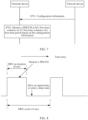
- FIG. 7 is a diagram of a communication method according to an embodiment of this application.
- a network device and a terminal device are execution bodies for interaction
- execution bodies for interaction are not limited in this application.
- the network device in FIG. 7 may be a chip, a chip system, or a processor that supports the network device in implementing the method, or may be a logical module or software that can implement all or some functions of the wireless network device.
- the terminal device in FIG. 7 may be a chip, a chip system, or a processor that supports the terminal device in implementing the method, or may be a logical module or software that can implement all or some functions of the terminal device.
- the method includes the following steps.
- S701 The network device sends configuration information to the terminal device, and the terminal device receives the configuration information from the network device.
- S702 The terminal device monitors a PDCCH in M1 first time windows in N1 first time windows of a first time period based on the configuration information.
- the configuration information may be used to configure the M1 first time windows that are in the N1 first time windows of the first time period and that are used to monitor the PDCCH.
- the first time period may be a period of continuous time in time domain.
- the first time period may be periodically distributed in time (which may also be referred to as time domain), or may be aperiodically distributed in time.
- the first time period may be a DRX on duration (on duration), and is distributed based on a DRX cycle in time.
- the first time period may be distributed based on a DRX cycle in time.
- the first time period may be a DRX cycle, that is, one DRX cycle may be one first time period, duration of the first time period is equal to a DRX cycle, and the first time period is distributed based on a DRX cycle in time.
- the first time period may be a wake-up time period of a wake-up signal (wake-up signal, WUS), or the like.
- WUS indicates the terminal device to monitor a PDCCH in a DRX on duration (which may also be referred to as a wake-up time period) of a next DRX cycle of a DRX cycle in which the WUS is received.
- the configuration information may be sent by the network device to the terminal device through radio resource control (radio resource control, RRC) signaling, downlink control information (downlink control information, DCI), or the like.
- radio resource control radio resource control, RRC
- DCI downlink control information
- the DRX on duration may alternatively be referred to as DRX duration, a DRX on period, a DRX on-time, or the like.
- the first time period is a DRX on duration.
- jitter values of service frames comply with truncated Gaussian distribution in which an average value is 0, a standard deviation is 2 ms, and a value range is [-4 ms, 4 ms], a service frame interval of the XR service is 16.67 ms.
- 16.67 ms is rounded to 16 ms in this embodiment of this application.
- a DRX cycle needs to be set to be 16 ms.
- the first time period (the DRX on duration) needs to be set to a time range that may be reached by the entire service frame, that is, the DRX on duration needs to be set to 8 ms, so that the time range [-4 ms, 4 ms] that may be reached by the entire service frame can be covered.
- the terminal device needs to monitor the PDCCH in half of time in the first time period, resulting in excessively high power consumption.
- a feature of probability distribution of the jitters of the service frames in time can be used.
- the N1 first time windows of the first time period can be set based on the configuration information, the terminal device is configured to monitor the PDCCH in the M1 first time windows of the N1 first time windows, and the terminal device does not monitor the PDCCH in remaining (N1-M1) first time windows and enters a sleep state.
- the time window may alternatively be referred to as a time raster (raster), a time sub-period, or the like.
- a name of the time window is not limited in this application.
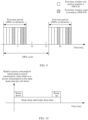
- duration of a first time window may be determined based on a slot length.
- duration of a first time window may be equal to a slot length, or may be an integer multiple of the slot length.
- a slot length is 1 ms.
- the first time period whose duration is 8 ms in FIG. 8 may include eight first time windows, the eight first time windows do not overlap each other, and duration of each first time window is 1 ms.
- the terminal device may enter the sleep state in five first time windows corresponding to duration from a 0 th ms to a 3 rd ms and duration from a 4 th ms to a 6 th ms in the first time period and do not monitor the PDCCH. This reduces power consumption.
- Table 1 shows an example of a relative power consumption value of a terminal device in a different state per unit time (for example, 1 ms).
- Table 1 shows an example of a relative power consumption value of a terminal device in a different state per unit time (for example, 1 ms).
- Table 1 shows an example of a relative power consumption value of a terminal device in a different state per unit time (for example, 1 ms).
- Table 1 shows an example of a relative power consumption value of a terminal device in a different state per unit time (for example, 1 ms).
- Table 1 shows an example of a relative power consumption value of a terminal device in a different state per unit time (for example, 1 ms).
- a power consumption value of the terminal device in the deep sleep state per unit time is represented as 1, as shown in Table 1, relative to power consumption of the terminal device in the deep sleep state per unit time, a relative power consumption value of the terminal device in the deep sleep state per unit time is 1, a relative power consumption value of the terminal device in the light sleep state per unit time is 20, a relative power consumption value of the terminal device in the micro sleep state per unit time is 45, a relative power consumption value of the terminal device per unit time is 100 when the terminal device monitors the PDCCH, and a relative power consumption value of the terminal device per unit time is 300 when both the PDCCH is monitored and a physical downlink shared channel (physical downlink shared channel, PDSCH) is received.
- a physical downlink shared channel physical downlink shared channel
- Table 1 Status Monitor a PDCCH Monitor a PDCCH+PDSCH Micro sleep (micro sleep) state Light sleep (light sleep) state Deep sleep (deep sleep) state Relative power consumption value 100 300 45 20 1
- switching time is required for the terminal device to switch from a monitoring state (for example, monitoring the PDCCH, or monitoring the PDCCH and receiving the PDSCH) to the sleep state, and then switch from the sleep state to the monitoring state, where switching time required for switching to the sleep state with lower power consumption is longer; and specific power is also consumed in a process of switching the terminal device from the monitoring state to the sleep state and then from the sleep state to the monitoring state.
- a monitoring state for example, monitoring the PDCCH, or monitoring the PDCCH and receiving the PDSCH
- Switching time required for switching from the monitoring state to a deep sleep state and then from the deep sleep state to the monitoring state and a total relative power consumption value in a switching phase are 20 ms and 450 respectively.
- Switching time required for switching from the monitoring state to a light sleep state and then from the light sleep state to the monitoring state and a total relative power consumption value in a switching phase are 60 ms and 100 respectively.
- Switching time required for switching from the monitoring state to a micro sleep state and then from the micro sleep state to the monitoring state and a total relative power consumption value in a switching phase are 0 ms and 0 respectively.
- Table 2 Sleep state Total relative power consumption value in a switching phase Switching time Deep sleep (Deep sleep) state 450 20 ms Light sleep (Light sleep) state 100 6 ms Micro sleep (Micro sleep) state 0 0 ms
- FIG. 10 is a diagram of relative power consumption values (namely, relative power consumption values relative to power consumption in the deep sleep state per unit time) required for switching from the monitoring state to the deep sleep state/light sleep state and then from the deep sleep state/light sleep state to the monitoring state.
- Duration of the deep sleep state/light sleep state includes duration of switching from the monitoring state to the deep sleep state/light sleep state and then from the deep sleep state/light sleep state to the monitoring state.
- a square box marked as ramp down (ramp down) represents relative power consumption values of switching from the monitoring state (for example, monitoring a PDCCH, or monitoring a PDCCH and receiving a PDSCH) to the deep sleep state/light sleep state.
- a square box marked as ramp up represents relative power consumption values of switching from the deep sleep state/light sleep state to the monitoring state.
- a rectangle box marked as the deep sleep state/light sleep state represents relative power consumption values of the deep sleep state/light sleep state.
- the relative power consumption values caused by one switching of the terminal device from the monitoring state to the deep sleep state/light sleep state and then from the deep sleep state/light sleep state to the monitoring state are sums of the total relative power consumption values (for example, shown in Table 2) corresponding to the deep sleep state/light sleep state in the switching phase and relative power consumption values (for example, shown in Table 1) when the terminal device is in the deep sleep state/light sleep state.
- duration of the first time period is 8 ms
- duration of each first time window is 0.5 ms
- the 16 first time windows of the first time period are sequentially a 1 st first time window, a 2 nd first time window, ..., and a 16 th first time window.
- the terminal device If the terminal device is in the deep sleep state in a non-monitoring state (a state of not monitoring the PDCCH), it takes 20 ms for the terminal device to switch from the monitoring state to the deep sleep state and then from the deep sleep state to the monitoring state. Because the maximum non-monitoring duration is 1.5 ms, the terminal device cannot switch from the non-monitoring state to the deep sleep state. Further, if the terminal device is in the light sleep state in the non-monitoring state, it takes 6 ms for the terminal device to switch from the monitoring state to the light sleep state and then from the light sleep state to the monitoring state. Because the maximum non-monitoring duration is only 1.5 ms, the terminal device cannot switch from the non-monitoring state to the light sleep state.
- the terminal device If the terminal device is in the micro sleep state in the non-monitoring state, it takes 0 ms for the terminal device to switch from the monitoring state to the micro sleep state and then from the micro sleep state to the monitoring state, that is, switching time is not required for the terminal device to switch from the monitoring state to the micro sleep state and then from the micro sleep state to the monitoring state. Therefore, the terminal device can switch from the non-monitoring state to the micro sleep state in the foregoing scenario.
- the terminal device monitors the PDCCH in the M1 first time windows in the N1 first time windows, and the terminal device may enter the sleep state in the remaining (N1-M1) first time windows. This can reduce power consumption of the terminal device.
- the network device may schedule, only in a first time window in which the terminal device monitors the PDCCH and that is closest to the first time window, the terminal device to receive the service frame. This causes a scheduling delay for transmission of the service frame.
- a probability of arrival of a service frame in an i th first time window is p i
- a quantity of first time windows is N1
- a delay corresponding to each first time window is d i .
- the first time period is a DRX on duration
- jitter values of service frames comply with truncated Gaussian distribution in which an average value is 0, a standard deviation is 2 ms, and a value range is [-4 ms, 4 ms], and duration of each first time window is 0.5 ms.
- Duration of the first time period is 8 ms, and there may be 16 first time windows of the first time period. As shown in FIG. 11 , a horizontal axis in FIG.
- a pattern, of the 16 first time windows, corresponding to the M1 first time windows is set to [0, 0, 0, 1, 0, 1, 0, 1, 0, 1, 0, 0, 0, 1], that is, the terminal device monitors the PDCCH in a 4 th first time window, a 6 th first time window, an 8 th first time window, a 10 th first time window, a 12 th first time window, and a 16 th first time window of the 16 first time windows
- the network device can not only configure, for the terminal device from a perspective of power consumption, the M1 first time windows that are in the N1 first time windows of the first time period and that are used to monitor the PDCCH, but also configure, for the terminal device from a perspective of factors such as the schedule delay or comprehensive consideration of factors such as the schedule delay and power consumption, the M1 first time windows that are in the N1 first time windows of the first time period and that are used to monitor the PDCCH.
- factors such as the schedule delay or comprehensive consideration of factors such as the schedule delay and power consumption
- a first time period is a discontinuous reception DRX on duration.
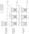
- FIG. 12 is a diagram of another communication method according to an embodiment of this application.
- a network device and a terminal device are execution bodies for interaction
- execution bodies for interaction are not limited in this application.
- the network device in FIG. 12 may be a chip, a chip system, or a processor that supports the network device in implementing the method, or may be a logical module or software that can implement all or some functions of the wireless network device.
- the terminal device in FIG. 12 may be a chip, a chip system, or a processor that supports the terminal device in implementing the method, or may be a logical module or software that can implement all or some functions of the terminal device.
- the method shown in FIG. 12 may be understood as a specific implementation of the method shown in FIG. 7 . The method includes the following steps.
- S1201 The network device sends configuration information to the terminal device, and the terminal device receives the configuration information from the network device.
- S1202 The terminal device monitors a PDCCH in M1 first time windows in N1 first time windows of a first time period based on the configuration information, where the first time period is a DRX on duration.
- the configuration information may be used to configure the M1 first time windows that are in the N1 first time windows of the first time period and that are used to monitor the PDCCH, where N1 is an integer greater than or equal to 2, and M1 is a positive integer less than N1.
- the configuration information includes time window index information, and the time window index information is used to configure the M1 first time windows.
- the M1 first time windows that are in the N1 first time windows of the first time period and that are used to monitor the PDCCH may be configured by using time window index information from the network device.
- one or more time window index tables may be configured in the network device and the terminal device in a manner of protocol predefinition, or in a manner of configuring by the network device and unicasting, multicasting, or broadcasting to the terminal device.
- Each entry in the time window index table corresponds to one first time window pattern, and each entry corresponds to one index value.
- one or more time window index tables may be configured for different service types, for example, different service frame rates, such as 60 FPS and 120 FPS, different subcarrier spacings, and a probability distribution and a value range of jitters of service frames.
- jitter values comply with truncated Gaussian distribution in which an average value is 0, a standard deviation is 2 ms, and a value range is [-4 ms, 4 ms], and a slot length is 0.5 ms.
- the first time period may be set to 8 ms, and duration of each first time window is set to 0.5 ms.
- the first time period includes 16 first time windows, and a corresponding time window index table may be shown in Table 3.
- Each first time window pattern in Table 3 includes 16 indicator bits corresponding to a 1 st first time window to a 16 th first time window of the first time period.
- An indicator bit 0 indicates that a corresponding first time window is not used to monitor a PDCCH, and an indicator bit 1 indicates that a corresponding first time window is used to monitor a PDCCH; or an indicator bit 0 indicates that a corresponding first time window is used to monitor a PDCCH, and an indicator bit 1 indicates that a corresponding first time window is not used to monitor the PDCCH.
- each entry in Table 3 corresponds to an index value, a relative power consumption value, an average schedule delay, and a first time window pattern.
- a corresponding entry may be located based on an index value.
- an entry with an index value 6 a relative power consumption value 525, an average schedule delay 0.397, and a first time window pattern [0, 0, 0, 1, 0, 0, 1, 0, 1, 0, 1, 0, 0, 1] may be located based on the index value 6.
- first time window patterns in Table 3 include different quantities of indicator bits " 1", that is, quantities of first time windows used to monitor a PDCCH are different.
- average schedule delays corresponding to all possible first time window patterns including the specific quantity of first time windows used to monitor a PDCCH may be determined in the foregoing manner of determining the average schedule delay, and a first time window pattern with a lowest average schedule delay is selected as the first time window pattern corresponding to the specific quantity of indicator bits "1".
- jitter values comply with truncated Gaussian distribution in which an average value is 0, a standard deviation is 2 ms, and a value range is [-4 ms, 4 ms], and a slot length is 1 ms.
- the first time period may be set to 8 ms, and duration of each first time window is set to 1 ms.
- the first time period includes eight first time windows, and a corresponding time window index table may be shown in Table 4.
- Each time window pattern in Table 4 includes eight indicator bits corresponding to a 1 st first time window to an 8 th first time window of the first time period.
- An indicator bit 0 indicates that a corresponding first time window is not used to monitor a PDCCH
- an indicator bit 1 indicates that a corresponding first time window is used to monitor a PDCCH.
- each entry in Table 4 corresponds to an index value, a relative power consumption value, an average schedule delay, and a first time window pattern. A corresponding entry may be located based on an index value.
- jitter values comply with truncated Gaussian distribution in which an average value is 0, a standard deviation is 3 ms, and a value range is [-6 ms, 6 ms], and a slot length is 0.25 ms.
- the first time period may be set to 12 ms, and duration of each first time window is set to 2 ms.
- the first time period includes six first time windows, and a corresponding time window index table may be shown in Table 5.
- Each time window pattern in Table 5 includes six indicator bits corresponding to a 1 st first time window to a 6 th first time window of the first time period.
- An indicator bit 0 indicates that a corresponding first time window is not used to monitor a PDCCH
- an indicator bit 1 indicates that a corresponding first time window is used to monitor a PDCCH.
- each entry in Table 5 corresponds to an index value, a relative power consumption value, an average schedule delay, and a first time window pattern. A corresponding entry may be located based on an index value.
- first time window patterns in Table 4 or Table 5 also include different quantities of indicator bits "1", that is, quantities of first time windows used to monitor a PDCCH are different.
- average schedule delays corresponding to all possible first time window patterns including the specific quantity of first time windows used to monitor a PDCCH may also be determined in the foregoing manner of determining the average schedule delay, and a first time window pattern with a lowest average schedule delay is selected as the first time window pattern corresponding to the specific quantity of indicator bits "1".
- an index value is equal to a quantity of indicator bits "1" in a first time window pattern corresponding to the index value.
- an index value may be unequal to a quantity of indicator bits "1" in a first time window pattern corresponding to the index value; or some index values are equal to quantities of indicator bits "1" in first time window patterns corresponding to the index values, and some index values are unequal to quantities of indicator bits "1" in first time window patterns corresponding to the index values. This is not limited in this application.
- Table 3 to Table 5 are merely examples. It may be understood that for different service types, for example, different jitter distribution parameters and duration of a first time window, a time window index table may change. In other words, for different service types, different time window index tables may be configured in embodiments of this application.
- some or all of the one or more time window index tables may alternatively be combined to form a new time window index table applicable to one or more different service types. For example, some entries (for example, a second row to a tenth row) in Table 3 may be extracted to form a new time window index table; or some entries in Table 3 and some entries in Table 4 may be extracted, and non-repeated index values are re-assigned to the entries to form a new time window index table.
- one of the relative power consumption value and the average schedule delay may appear in the time window index table, or the relative power consumption value and the average schedule delay may not appear in the time window index table.
- the relative power consumption value, the average schedule delay, and the like in the time window index table may alternatively be replaced with one value.
- a performance value may be used to comprehensively measure the relative power consumption value and the average schedule delay, and the performance value is used to replace the relative power consumption value and the average schedule delay in the time window index table, where the performance value may be a weighted average value, a product, or the like of the relative power consumption value and the average schedule delay.
- the network device may select, according to a specific strategy, an index value from the time window index table as the time window index information included in the configuration information. For example, the network device may select, in a random selection manner, an index value from the time window index table as the time window index information included in the configuration information; or may select an index value (for example, the index value 6) by default as the time window index information included in the configuration information; or may select an index value as the time window index information included in the configuration information based on a requirement of the terminal device on a power consumption reduction proportion (a proportion relative to a relative power consumption value when the first time period is totally used to monitor the PDCCH) or an average schedule delay; or select an index value as the time window index information included in the configuration information by comprehensively considering requirements of the terminal device on the power consumption reduction proportion and the average schedule delay.
- a power consumption reduction proportion a proportion relative to a relative power consumption value when the first time period is totally used to monitor the PDCCH
- an average schedule delay or select an index value as the time window index information included
- the time window index information may be carried (or configured) in a setting field (or an information element) in DCI or RRC signaling in the sent configuration information.
- a setting field or an information element
- the time window index information is carried in a setting field is used for description.
- a discontinuous reception on duration raster (DRX on duration raster, DODR) index (DODR-index) field is set for carrying.
- the terminal device may determine a first time window pattern based on the time window index information, monitor the PDCCH in the M1 first time windows in the first time window pattern, and do not monitor the PDCCH in the (N1-M1) first time windows. This reduces power consumption.
- the configuration information includes time window bitmap (bitmap) information, and the time window bitmap information is used to configure the M1 first time windows.
- the M1 first time windows that are in the N1 first time windows of the first time period and that are used to monitor the PDCCH may alternatively be configured by using time window bitmap information from the network device.
- the time window bitmap information may be carried (or configured) in a setting field (or an information element) in DCI or RRC signaling in the sent configuration information.
- a DODR bitmap (DODR-bitmap) field may be set in the configuration information to carry the time window bitmap information.
- a quantity of indicator bits in the time window bitmap information may be equal to N1.
- a first indicator bit in the time window bitmap information indicates whether a 1 st first time window of the first time period is used to monitor the PDCCH
- a second indicator bit in the time window bitmap information indicates whether a 2 nd first time window of the first time period is used to monitor the PDCCH
- a third indicator bit in the time window bitmap information indicates whether a 3 rd first time window of the first time period is used to monitor the PDCCH, and so on.
- an indicator bit 1 indicates that a first time window is used to monitor a PDCCH, and an indicator bit 0 indicates that a first time window is not used to monitor a PDCCH; or an indicator bit 0 indicates that a first time window is used to monitor a PDCCH, and an indicator bit 1 indicates that a first time window is not used to monitor a PDCCH.
- an indicator bit 1 indicates that a first time window is used to monitor a PDCCH
- an indicator bit 0 indicates that a first time window is not used to monitor a PDCCH
- time window bitmap information is "[0, 0, 0, 1, 0, 0, 1, 1]"
- it indicates that a 4 th first time window, a 7 th first time window, and an 8 th first time window of eight first time windows of a first time period are used to monitor a PDCCH, and other first time windows are not used to monitor the PDCCH.
- the first time window pattern in Table 3, Table 4, or Table 5 is used as an example.
- One first time window pattern corresponding to one index value in Table 3, Table 4, or Table 5 may be considered as one piece of candidate time window bitmap information.
- the network device may select, according to a specific strategy, one of pieces of candidate time window bitmap information as the time window bitmap information in the configuration information.
- one of the pieces of candidate time window bitmap information may be randomly selected as the time window bitmap information in the configuration information.
- one of the pieces of candidate time window bitmap information is selected as the time window bitmap information in the configuration information based on a priority of a lowest relative power consumption value or a lowest average schedule delay.
- the terminal device may determine, based on the time window bitmap information included in the configuration information, the M1 first time windows used to monitor the PDCCH in the first time period.
- time window bitmap information is "[0, 0, 0, 1, 0, 0, 1, 1]", and duration of a first time period is 8 ms. If a quantity of indicator bits in the time window bitmap information is 8, a quantity of first time windows of the first time period is 8.
- the terminal device determines, based on the time window bitmap information, to monitor a PDCCH in a 4 th first time window, a 7 th first time window, and an 8 th first time window of the first time period.
- a quantity of indicator bits in the DODR-bitmap field may be greater than a value of the quantity N1 of first time windows of the first time period.
- the time window bitmap information actually occupies some indicator bits in the DODR-bitmap field.
- a quantity of indicator bits in a DODR-bitmap field is 20, and a value of N1 is 8.
- time window bitmap information in configuration information occupies eight indicator bits in the DODR-bitmap field, and other indicator bits in the DODR-bitmap field may be filled with 0.
- the configuration information may alternatively be used to configure the value of N1 or duration of one of the N1 first time windows.
- the value of N1 or the duration of one of the N1 first time windows may be carried (configured) in a setting field (or an information element) in DCI or RRC signaling in the sent configuration information.
- a DODR number (DODR-num) field is set to configure the value of N1. If the duration of the first time period is 8 ms, the quantity of indicator bits in the time window bitmap information is 8, and the quantity of indicator bits in the DODR-bitmap field is 20, the network device may configure the value of N1 to 8 based on the DODR-num field.
- the terminal device may determine, in a manner such as a specification of a protocol or a configuration of the network device, eight specific indicator bits in the DODR-bitmap field are occupied by the time window bitmap information, for example, first eight indicator bits or last eight indicator bits in the DODR-bitmap field are occupied.
- a DODR time granularity (DODR-timegranularity) field is set to configure the duration of one of the N1 first time windows. If the duration of the first time period is 8 ms, the quantity N1 of first time windows of the first time period is 8, the duration of one first time window is 1 ms, the quantity of indicator bits in the time window bitmap information is 8, and the quantity of indicator bits in the DODR-bitmap field is 20, the network device may configure the duration of one of the N1 first time windows to 1 ms based on the DODR-timegranularity field.
- the terminal device may determine, based on a case that the duration of the first time period is 8 ms and the duration of one of the N1 first time windows is 1 ms, that the quantity N1 of first time windows of the first time period is 8 and the quantity of indicator bits in the time window bitmap information is 8.
- the terminal device may determine, in a manner such as a specification of a protocol or a configuration of the network device, eight specific indicator bits in the DODR-bitmap field are occupied by the time window bitmap information, for example, first eight indicator bits or last eight indicator bits in the DODR-bitmap field are occupied.
- the terminal device may also send DRX preference information to the network device, and the network device receives the DRX preference information from the terminal device.
- the DRX preference information indicates a preference for power consumption and/or a preference for a delay.
- the network device may consider power consumption reduction or an average schedule delay caused by the M1 first time windows that are in the N1 first time windows of the first time period and that are used to monitor the PDCCH and that are configured by using the configuration information, to meet the DRX preference information reported by the terminal device.
- the preference for power consumption and/or the preference for the delay may be a preference for power consumption reduction, or a preference for a low average schedule delay, or may be a power consumption level desired by the terminal device, for example, 20% power consumption reduction, or may be an average schedule delay that can be accepted by the terminal device, for example, a maximum average schedule delay is 0.3 ms.
- the terminal device may send the DRX preference information to the network device by using user assistance information (UE assistance information, UAI).
- UE assistance information UAI
- a preferred DODR type (preferred DODR-type) field may be added to the UAI to represent whether the terminal device prefers power consumption reduction or the low average schedule delay. For example, if the preferredDODR-type field is 0, it indicates that the terminal device prefers power consumption reduction; or if the preferredDODR-type field is 1, it indicates that the terminal device prefers the low average schedule delay.
- the preferredDODR-type field is an enumerated value "power”, it indicates that the terminal device prefers power consumption reduction; or if the preferredDODR-type field is an enumerated value "delay”, it indicates that the terminal device prefers the low average schedule delay.
- a preferred DODR power consumption (preferredDODR-power-consumption) field may be added to the UAI to represent the desired power consumption level.
- a DODR average schedule delay (preferredDODR-average-schedule-delay) field may alternatively be added to the UAI to represent the average schedule delay that can be accepted.
- the network device selects a first time window pattern with low power consumption (for example, a relative power consumption value) and configures the first time window pattern for the terminal device by using the configuration information. For example, the network device selects a first time window pattern from X first time window patterns with lowest power consumption and configures the first time window pattern for the terminal device by using the configuration information, where X is an integer greater than or equal to 1. In an example, a value of X may be 4. If the preferredDODR-type field in the UAI sent by the terminal device is 0, the network device may select a first time window pattern from four first time window patterns with lowest power consumption and configure the first time window pattern for the terminal device by using the configuration information.
- a first time window pattern with low power consumption for example, a relative power consumption value
- the network device selects a first time window pattern with a low average schedule delay and configures the first time window pattern for the terminal device by using the configuration information. For example, the network device selects a first time window pattern from Y first time window patterns with a lowest average schedule delay and configures the first time window pattern for the terminal device by using the configuration information, where Y is an integer greater than or equal to 1. In an example, a value of Y may be 3. If the preferredDODR-type field in the UAI sent by the terminal device is 1, the network device may select a first time window pattern from three first time window patterns with a lowest average schedule delay and configure the first time window pattern for the terminal device by using the configuration information.
- the network device may select, based on the power consumption level indicated by the preferredDODR-power-consumption field, the first time window pattern and configure the first time window pattern for the terminal device by using the configuration information. If there is the preferredDODR-average-schedule-delay field in the UAI, it indicates that there is an average schedule delay level indication. In this case, the network device may select, based on the average schedule delay level indicated by the preferredDODR-average-schedule-delay field, the first time window pattern and configure the first time window pattern for the terminal device by using the configuration information.
- the network device may select, based on the power consumption level indicated by the preferredDODR-power-consumption field and the average schedule delay level indicated by the preferredDODR-average-schedule-delay field, the first time window pattern and configure the first time window pattern for the terminal device by using the configuration information.
- an indicated power consumption level is 20% power consumption reduction.
- Table 3 is used as an example.
- the network device may select a first time window pattern from first time window patterns corresponding to the index 1 to the index 10, and configure the first time window pattern for the terminal device. Therefore, more than 20% power consumption reduction can be implemented with the first time window pattern corresponding to the index 1 to the index 10 relative to the first time window pattern corresponding to the index 16 (that is, all the first time windows are used to monitor the PDCCH).
- FIG. 13 shows a ratio of power consumption corresponding to each first time window pattern shown in Table 3 to power consumption of continuously monitoring the PDCCH in the first time period and an average schedule delay corresponding to each first time window pattern.
- each point represents one first time window pattern
- a horizontal axis represents an average schedule delay
- a vertical axis represents a ratio of power consumption of a first time window pattern to power consumption of continuously monitoring the PDCCH in the first time period
- points from left to right on the horizontal axis sequentially correspond to the first time window pattern with the index 16, the first time window pattern with the index 15, ..., and the first time window pattern with the index 1 in Table 3.
- the terminal device may configure two DRX cycles, namely, one long DRX cycle and one short DRX cycle. At a moment, the terminal device uses one of the two DRX cycles for configuration. In an example, as shown in FIG.
- the network device may configure a long DRX cycle and a short DRX cycle for the terminal device, duration of the long DRX cycle is twice duration of the short DRX cycle, and duration of a DRX on duration of the long DRX cycle may be the same as duration of a DRX on duration of the short DRX cycle.
- a group of pictures may include one I frame (intra frame) and a plurality of P frames (predicted frames).
- the I frame is an intra frame reference frame, and a terminal device restores a picture based on data of the I frame during decoding.
- the P frame is a predicted-coded frame, and represents data different from that of a picture of a previous frame.
- the terminal device needs to superimpose a previously buffered picture frame with a difference defined by the I frame to generate a picture. Because the previous picture frame needs to be referred to when the P frame is decoded, the terminal device needs longer decoding time. Therefore, it is required that an air interface should complete transmission within shorter time.
- a transmission delay budget of the air interface for the P frame may be 8 ms.
- a transmission delay budget of the air interface for the I frame may be 12 ms. Therefore, when the video service is performed, a pattern corresponding to a time window that is used to monitor a PDCCH and that has a shorter average schedule delay may be configured for the P frame, and a pattern corresponding to a time window that is used to monitor a PDCCH and that has a longer average schedule delay may be configured for the I frame.
- one GOP may include one I frame and a plurality of P frames, and an interval between two adjacent I frames is greater than an interval between two adjacent P frames.
- the network device may configure a short DRX cycle for the terminal device based on the interval between the P frames, configure a long DRX cycle for the terminal device based on the interval between the I frames, and separately configure, for a DRX on duration in the long DRX cycle and a DRX on duration in the short DRX cycle, patterns corresponding to time windows used to monitor a PDCCH with different delays.
- the first time period is a DRX on duration of the long DRX cycle.
- the configuration information sent by the network device to the terminal device may alternatively be used to configure M2 second time windows that are in N2 second time windows of a second time period and that are used to monitor the PDCCH, where the second time period is a DRX on duration of a short DRX cycle, N2 is an integer greater than or equal to 2, and M2 is a positive integer less than N2.
- the terminal device may further monitor the PDCCH in the M2 second time windows in the N2 second time windows of the second time period based on the configuration information.
- the network device configures, by using the configuration information, the M2 second time windows that are in the N2 second time windows of the second time period and that are used to monitor the PDCCH
- the network device configures, by using the configuration information, the M1 first time windows that are in the N1 first time windows of the first time period and that are used to monitor the PDCCH.
- a DODR-index2 field is added to carry time window index information of the M2 second time windows that are in the N2 second time windows of the second period and that are used to monitor the PDCCH
- a DODR-bitmap2 field is added to carry time window bitmap information of the M2 second time windows that are in the N2 second time windows of the second period and that are used to monitor the PDCCH.
- the terminal device for the first time period and the second time period that do not overlap, that is, there is no overlapping between the first time period and the second time period in time, the terminal device not only monitors the PDCCH in the M1 first time windows of the first time period, but also monitors the PDCCH in the M2 second time windows of the second time period.
- the terminal device may monitor the PDCCH only in the M1 first time windows of the first time period.
- the long DRX cycle is 30 ms
- the short DRX cycle is 10 ms
- the DRX on duration of the long DRX cycle and the DRX on duration of the short DRX cycle are both 5 ms
- duration of a first time window and duration of a second time window are both 1 ms.
- a first time window pattern of the DRX on duration of the long DRX cycle is [1, 0, 1, 0, 1]
- a second time window pattern of the DRX on duration of the short DRX cycle is [0, 1, 1, 1, 1].
- Scenario 2 Duration of a first time period is a DRX cycle.
- FIG. 16 is a diagram of another communication method according to an embodiment of this application.
- a network device and a terminal device are execution bodies for interaction
- execution bodies for interaction are not limited in this application.
- the network device in FIG. 16 may be a chip, a chip system, or a processor that supports the network device in implementing the method, or may be a logical module or software that can implement all or some functions of the wireless network device.
- the terminal device in FIG. 16 may be a chip, a chip system, or a processor that supports the terminal device in implementing the method, or may be a logical module or software that can implement all or some functions of the terminal device.
- the method shown in FIG. 16 may be understood as a specific implementation of the method shown in FIG. 7 . The method includes the following steps.
- S1601 The network device sends configuration information to the terminal device, and the terminal device receives the configuration information from the network device.
- S1602 The terminal device monitors a PDCCH in M1 first time windows in N1 first time windows of a first time period based on the configuration information, where duration of the first time period is a DRX cycle.
- the configuration information may be used to configure the M1 first time windows that are in the N1 first time windows of the first time period and that are used to monitor the PDCCH, where N1 is an integer greater than or equal to 3, and M1 is an integer less than N1 and greater than or equal to 2.
- the M1 first time windows used to monitor the PDCCH are deployed in a decentralized manner in the DRX cycle, that is, there are at least two first time windows that are inconsecutive in time in the M1 first time windows.
- the duration of the first time period is 16 ms
- a first time window pattern is [0, 0, 0, 1, 0, 0, 1, 1, 0, 0, 0, 0, 0, 0], where 1 in the first time window pattern indicates that a first time window is used to monitor a PDCCH, and 0 indicates that the first time window is not used to monitor the PDCCH.
- the first time period is divided into 16 first time windows, duration of one first time window is 1 ms, and a 4 th first time window, and a 7 th first time window and an 8 th first time window of the first time period that correspond to duration between a 3 rd ms and a 4 th ms and duration from a 6 th ms to an 8 th ms respectively are used to monitor the PDCCH, and other time windows are not used to monitor the PDCCH.
- the 4 th first time window and the 7 th first time window are inconsecutive in time.
- the configuration information includes time window index information, and the time window index information is used to configure the M1 first time windows.
- the M1 first time windows that are in the N1 first time windows of the first time period and that are used to monitor the PDCCH may be configured by using time window index information from the network device.
- one or more time window index tables may be configured in the network device and the terminal device in a manner of protocol predefinition, or in a manner of configuring by the network device and unicasting, multicasting, or broadcasting to the terminal device.
- Each entry in the time window index table corresponds to one first time window pattern, and each entry corresponds to one index value. It may be understood that at least one first time window pattern in the time window index table meets a condition that there are at least two first time windows that are inconsecutive in time in the M1 first time windows that are in the N1 first time windows of the first time period and that are used to monitor the PDCCH.
- the first time window pattern in the time window index table shown in Table 4 is used as an example.
- the first time window patterns corresponding to the index values 1, 7, and 8 in Table 4 do not meet the condition that there are at least two first time windows that are inconsecutive in time in the M1 first time windows that are in the N1 first time windows of the first time period and that are used to monitor the PDCCH. Therefore, the first time window pattern corresponding to the M1 first time windows that are in the N1 first time windows of the first time period and that are configured by the network device by using the configuration information is ensured to not correspond to the first time window patterns with the index values 1, 7, and 8.
- the entries corresponding to the index values 1, 7, and 8 in Table 4 may alternatively be deleted.
- the network device selects, from the first time window patterns corresponding to the index values 2 to 6, a first time window pattern corresponding to the M1 first time windows that are in the N1 first time windows of the first time period and that are configured by using the configuration information.
- the time window index information may be carried (or configured) in a setting field (or an information element) in DCI or RRC signaling in the sent configuration information.
- a discontinuous reception raster (DRX raster, DR) index (DR-index) field is set for carrying.
- the terminal device may determine a first time window pattern based on the time window index information, monitor the PDCCH in the M1 first time windows in the first time window pattern, and do not monitor the PDCCH in (N1-M1) first time windows.
- the M1 first time windows that are in the N1 first time windows of the first time period and that are used to monitor the PDCCH may alternatively be configured by using time window bitmap information from the network device. It should be understood that, a first time window pattern configured by using the time window bitmap information also meets that there are at least two first time windows that are inconsecutive in time in the M1 first time windows that are in the N1 first time windows of the first time period and that are used to monitor the PDCCH.
- the time window bitmap information may be carried (or configured) in a setting field (or an information element) in DCI or RRC signaling in the sent configuration information.
- a DR bitmap (DR-bitmap) field is set in the configuration information to carry the time window bitmap information.
- a quantity of indicator bits in the time window bitmap information may be equal to N1.
- a first indicator bit in the time window bitmap information indicates whether a 1 st first time window of the first time period is used to monitor the PDCCH
- a second indicator bit in the time window bitmap information indicates whether a 2 nd first time window of the first time period is used to monitor the PDCCH
- a third indicator bit in the time window bitmap information indicates whether a 3 rd first time window of the first time period is used to monitor the PDCCH, and so on.
- an indicator bit 1 indicates that a first time window is used to monitor a PDCCH, and an indicator bit 0 indicates that a first time window is not used to monitor a PDCCH; or an indicator bit 0 indicates that a first time window is used to monitor a PDCCH, and an indicator bit 1 indicates that a first time window is not used to monitor a PDCCH.
- an indicator bit 1 indicates that a first time window is used to monitor a PDCCH
- an indicator bit 0 indicates that a first time window is not used to monitor a PDCCH
- a quantity of indicator bits in the DR-bitmap field may be greater than a value of N1, and the time window bitmap information actually occupies only some indicator bits in the DR-bitmap field.
- the quantity of indicator bits in the DR-bitmap field is 20, and the value of N1 is 16.
- the time window bitmap information in the configuration information occupies 16 indicator bits in the DR-bitmap field, and other indicator bits in the DR-bitmap field may be filled with 0.
- the configuration information may alternatively be used to configure a value of N1 or duration of one of the N1 first time windows.
- the value of N1 or the duration of one of the N1 first time windows may be carried (configured) in a setting field (or an information element) in DCI or RRC signaling in the sent configuration information.
- a DR number (DR-num) field is set to configure the value of N1. If the duration of the first time period is 16 ms, the quantity of indicator bits in the time window bitmap information is 16, and the quantity of indicator bits in the DR-bitmap field is 20, the network device may configure the value of N1 to 16 based on the DR-num field.
- the terminal device may determine, in a manner such as a specification of a protocol or a configuration of the network device, 16 specific indicator bits in the DR-bitmap field are occupied by the time window bitmap information, for example, first 16 indicator bits or last 16 indicator bits in the DR-bitmap field are occupied.
- a DR time granularity (DR-timegranularity) field is set to configure the duration of one of the N1 first time windows. If the duration of the first time period is 16 ms, the quantity N1 of first time windows of the first time period is 16, the duration of one first time window is 1 ms, the quantity of indicator bits in the time window bitmap information is 16, and the quantity of indicator bits in the DR-bitmap field is 20, the network device may configure the duration of one of the N1 first time windows to 1 ms based on the DR-timegranularity field.
- the terminal device may determine, based on a case that the duration of the first time period is 16 ms and the duration of one of the N1 first time windows is 1 ms, that the quantity N1 of first time windows of the first time period is 16 and the quantity of indicator bits in the time window bitmap information is 16.
- the terminal device may determine, in a manner such as a specification of a protocol or a configuration of the network device, 16 specific indicator bits in the DR-bitmap field are occupied by the time window bitmap information, for example, first 16 indicator bits or last 16 indicator bits in the DODR-bitmap field are occupied.
- the terminal device may also send DRX preference information to the network device, and the network device receives the DRX preference information from the terminal device.
- the DRX preference information indicates a preference for power consumption and/or a preference for a delay.
- the network device may consider power consumption reduction and/or an average schedule delay caused by the M1 first time windows that are in the N1 first time windows of the first time period and that are used to monitor the PDCCH and that are configured by using the configuration information, to meet the DRX preference information reported by the terminal device.
- an implementation of sending, by the terminal device, the DRX preference information to the network device and how the network device selects a first time window pattern based on the DRX preference information and configures the first time window pattern for the terminal device by using the configuration information is similar to the implementation in Scenario 1. Details are not described again.
- the terminal device may continue to be scheduled in next several slots. If the terminal device receives or sends the data in a next DRX cycle, an extra delay is caused.
- the terminal device configures an activity period, and starts a DRX activity timer (DRX activity timer). As shown in FIG. 18 , after obtaining PDCCH scheduling in a DRX on duration, the terminal device starts a DRX activity timer, and continuously monitors a PDCCH in an activity period until the DRX activity timer expires. If there is new PDCCH scheduling during monitoring of the PDCCH, the DRX activity timer is restarted.
- the network device may send a DRX command (DRX command) to the terminal device by using a MAC CE.
- a DRX command MAC CE namely, a MAC CE carrying the DRX command
- the terminal device stops the DRX on duration and the DRX activity timer, and enters the sleep state.
- the terminal device After obtaining PDCCH scheduling in a first time window used to monitor a PDCCH, the terminal device starts a DRX activity timer, and continuously monitors the PDCCH in an activity period until the DRX activity timer expires. If there is new PDCCH scheduling during monitoring of the PDCCH, the DRX activity timer is restarted.
- the terminal device When monitoring a PDCCH in a first time window or an activity period in a DRX cycle, the terminal device stops a DRX activity timer after receiving a DRX command MAC CE, stops monitoring the PDCCH in a remaining first time window in the DRX cycle, and enters a sleep state.
- the terminal device is scheduled and receives or sends data continuously. After the terminal device is scheduled and receives or sends data in one slot, the data may be scheduled in next several slots. For example, the terminal device receives one or more data packets of a video frame in a slot, and remaining data packets of the video frame are scheduled in next several slots. Therefore, in some implementations, the terminal device receives PDCCH scheduling in a first time window used to monitor a PDCCH, and after the started DRX activity timer expires, stops monitoring the PDCCH in a remaining first time window in a current DRX cycle.
- the terminal device receives PDCCH scheduling in a first time window used to monitor a PDCCH, after the DRX activity timer is started, the terminal device continues to monitor the PDCCH only in an activity period in which the DRX activity timer does not expire in a current DRX cycle. If the DRX activity timer expires, even if there is still a first time window that can be used to monitor the PDCCH in the DRX cycle in which the DRX activity timer is started, the terminal device no longer monitors the PDCCH, but enters a sleep state. This reduces power consumption.
- duration of the first time period is a DRX cycle
- a first time window pattern is [0, 1, 0, 0, 0, 0, 1, 1, 0, 0, 0, 0, 0, 0, 0]
- duration of one first time window is 1 ms
- timing duration of a DRX activity timer is 4 ms.
- the terminal device needs to monitor the PDCCH in a 2 nd first time window, a 7 th first time window, and an 8 th first time window.
- the terminal device If the terminal device detects PDCCH scheduling in the 2 nd first time window through monitoring, the terminal device starts a DRX activity timer, and the terminal device continues to monitor the PDCCH in an activity period (a 3 rd first time window to a 6 th first time window) in which the DRX activity timer does not expire. If the terminal device does not receive PDCCH scheduling in the activity period again, after the DRX activity timer expires, the terminal device does not monitor the PDCCH in the 7 th first time window to a 16 th first time window.
- the first time window pattern is not limited to being represented in a binary form, that is, the first time window pattern is not limited to having only 0 and 1.
- the first time window pattern may alternatively be represented in an octal form, a hexadecimal form, or the like.
- an indicator bit in the first time window pattern may be any value of 0, 1, 2, 3, 4, 5, 6, 7, 8, 9, A, B, C, D, E or F.
- An indicator bit 0 indicates that a first time window corresponding to the indicator bit is not used to monitor a PDCCH, and an indicator bit (for example, any value of 1 to 9 or A to F) except the indicator bit 0 indicates that a first time window corresponding to the indicator bit is used to monitor a PDCCH.
- a network device and a terminal device include corresponding hardware structures and/or software modules for performing the functions.
- a person skilled in the art should be easily aware that, in this application, the units and method steps in the examples described with reference to embodiments disclosed in this application can be implemented by hardware or a combination of hardware and computer software. Whether a function is performed by hardware or hardware driven by computer software depends on particular application scenarios and design constraints of the technical solutions.
- FIG. 20 and FIG. 21 each are a diagram of a possible structure of a communication apparatus according to an embodiment of this application.
- the communication apparatus may be configured to implement functions of the terminal device or the network device in the foregoing method embodiments. Therefore, beneficial effect of the foregoing method embodiments can also be implemented.
- the communication apparatus may be one of the terminal devices 120a to 120j shown in FIG. 2 , or may be the network device 110a or 110b shown in FIG. 2 , or may be a module (for example, a chip) used in a terminal device or a network device.
- the communication apparatus 2000 includes a processing unit 2010 and an interface unit 2020.
- the communication apparatus 2000 is configured to implement the functions of the terminal device or the network device in the method embodiment shown in FIG. 12 or FIG. 16 .
- the communication apparatus 2000 When the communication apparatus 2000 is configured to implement the functions of the terminal device in the method embodiment shown in FIG. 12 :
- the configuration information includes time window bitmap information, and the time window bitmap information is used to configure the M1 first time windows.
- the configuration information is further used to configure a value of N1 or duration of one of the N1 first time windows.
- the configuration information includes time window index information, and the time window index information is used to configure the M1 first time windows.
- a first time window pattern corresponding to the M1 first time windows is one of a plurality of first time window patterns.
- the interface unit 2020 is further configured to send DRX preference information to the network device, where the DRX preference information indicates a preference for power consumption and/or a preference for a delay.
- the processing unit 2010 is further configured to control, based on the configuration information, the communication apparatus 2000 to monitor the PDCCH in M2 second time windows in N2 second time windows of a second time period, where the first time period is a DRX on duration of a long DRX cycle, the second time period is a DRX on duration of a short DRX cycle, N2 is an integer greater than or equal to 2, and M2 is a positive integer less than N2.
- the processing unit 2010 is further configured to obtain M2 second time windows in N2 second time windows of a second time period based on the configuration information, where the first time period is a DRX on duration of a long DRX cycle, the second time period is a DRX on duration of a short DRX cycle, N2 is an integer greater than or equal to 2, and M2 is a positive integer less than N2.
- the processing unit 2010 is further configured to: when the first time period and the second time period do not overlap in time, control the communication apparatus 2000 to monitor the PDCCH in the M2 second time windows.
- That the processing unit 2010 controls the communication apparatus 2000 to monitor the PDCCH in the M1 first time windows in the N1 first time windows of the first time period includes: when the first time period and the second time period overlap in time, controlling the communication apparatus 2000 to monitor the PDCCH in the M1 first time windows.
- the configuration information includes time window bitmap information, and the time window bitmap information is used to configure the M1 first time windows.
- the configuration information is further used to configure a value of N1 or duration of one of the N1 first time windows.
- the configuration information includes time window index information, and the time window index information is used to configure the M1 first time windows.
- a first time window pattern corresponding to the M1 first time windows is one of a plurality of first time window patterns.
- the interface unit 2020 is further configured to send DRX preference information to the network device, where the DRX preference information indicates a preference for power consumption and/or a preference for a delay.
- the communication apparatus 2000 When the communication apparatus 2000 is configured to implement the functions of the network device in the method embodiment shown in FIG. 12 :
- the configuration information includes time window bitmap information, and the time window bitmap information is used to configure the M1 first time windows.
- the configuration information is further used to configure a value of N1 or duration of one of the N1 first time windows.
- the configuration information includes time window index information, and the time window index information is used to configure the M1 first time windows.
- a first time window pattern corresponding to the M1 first time windows is one of a plurality of first time window patterns.
- the interface unit 2020 is further configured to receive DRX preference information from the terminal device, where the DRX preference information indicates a preference for power consumption and/or a preference for a delay.
- the configuration information is further used to configure M2 second time windows in N2 second time windows of a second time period, the M2 second time windows are used to monitor the PDCCH, the first time period is a DRX on duration of a long DRX cycle, the second time period is a DRX on duration of a short DRX cycle, N2 is an integer greater than or equal to 2, and M2 is a positive integer less than N2.
- the communication apparatus 2000 When the communication apparatus 2000 is configured to implement the functions of the network device in the method embodiment shown in FIG. 16 :
- the configuration information includes time window bitmap information, and the time window bitmap information is used to configure the M1 first time windows.
- the configuration information is further used to configure a value of N1 or duration of one of the N1 first time windows.
- the configuration information includes time window index information, and the time window index information is used to configure the M1 first time windows.
- a first time window pattern corresponding to the M1 first time windows is one of a plurality of first time window patterns.
- the interface unit 2020 is further configured to receive DRX preference information from the terminal device, where the DRX preference information indicates a preference for power consumption and/or a preference for a delay.
- the communication apparatus 2100 includes a processor 2110 and an interface circuit 2120.
- the processor 2110 and the interface circuit 2120 are coupled to each other.
- the interface circuit 2120 may be a transceiver or an input/output interface.
- the communication apparatus 2100 may further include a memory 2130, configured to: store instructions executed by the processor 2110, or store input data required by the processor 2110 to run the instructions, or store data generated after the processor 2110 runs the instructions.
- the processor 2110 is configured to implement the function of the processing unit 2010, and the interface circuit 2120 is configured to implement the function of the interface unit 2020.
- the chip in the terminal device implements the function of the terminal device in the foregoing method embodiments.
- the chip in the terminal device receives information from another module (for example, a radio frequency module or an antenna) in the terminal device, where the information is sent by a network device to the terminal device.
- the chip in the terminal device sends information to another module (for example, a radio frequency module or an antenna) in the terminal device, where the information is sent by the terminal device to a network device.
- the module in the network device implements a function of the network device in the foregoing method embodiments.
- the module in the network device receives information from another module (for example, a radio frequency module or an antenna) in the network device, where the information is sent by a terminal device to the network device.
- the module in the network device sends information to another module (for example, a radio frequency module or an antenna) in the network device, where the information is sent by the network device to a terminal device.
- the network device module herein may be a baseband chip of the network device, or may be a DU or another module.
- the DU herein may be a DU in an open radio access network (open radio access network, O-RAN) architecture.
- the processor in embodiments of this application may be a central processing unit (central processing unit, CPU), or may be another general-purpose processor, a digital signal processor (digital signal processor, DSP), an application-specific integrated circuit (application-specific integrated circuit, ASIC), a field programmable gate array (field programmable gate array, FPGA) or another programmable logic device, a transistor logic device, a hardware component, or any combination thereof.
- the general-purpose processor may be a microprocessor or any regular processor or the like.
- the method steps in embodiments of this application may be implemented in a hardware manner, or may be implemented in a manner of executing software instructions by the processor.
- the software instructions may include a corresponding software module.
- the software module may be stored in a random access memory, a flash memory, a read-only memory, a programmable read-only memory, an erasable programmable read-only memory, an electrically erasable programmable read-only memory, a register, a hard disk, a removable hard disk, a CD-ROM, or any other form of storage medium well-known in the art.
- a storage medium is coupled to a processor, so that the processor can read information from the storage medium and write information into the storage medium.
- the storage medium may be a component of the processor.
- the processor and the storage medium may be disposed in an ASIC.
- the ASIC may be located in a network device or a terminal device.
- the processor and the storage medium may alternatively exist as discrete components in a network device or a terminal device.
- All or some of the foregoing embodiments may be implemented by using software, hardware, firmware, or any combination thereof.
- software is used to implement the embodiments, all or a part of the embodiments may be implemented in a form of a computer program product.
- the computer program product includes one or more computer programs or instructions. When the computer programs or instructions are loaded and executed on a computer, all or some of the procedures or functions in embodiments of this application are executed.
- the computer may be a general-purpose computer, a dedicated computer, a computer network, a network device, user equipment, or another programmable apparatus.
- the computer programs or instructions may be stored in a computer-readable storage medium, or may be transmitted from a computer-readable storage medium to another computer-readable storage medium.
- the computer programs or instructions may be transmitted from a website, computer, server, or data center to another website, computer, server, or data center in a wired or wireless manner.
- the computer-readable storage medium may be any usable medium that can be accessed by the computer, or a data storage device, for example, a server or a data center, integrating one or more usable media.
- the usable medium may be a magnetic medium, for example, a floppy disk, a hard disk, or a magnetic tape; or may be an optical medium, for example, a digital video disc; or may be a semiconductor medium, for example, a solid-state drive.
- the computer-readable storage medium may be a volatile or non-volatile storage medium, or may include two types of storage media: a volatile storage medium and a non-volatile storage medium.
- information information
- a signal signal
- a message messages
- a channel channel
- meanings expressed by the terms are consistent when differences are not emphasized.
- Terms “of (of)” and “corresponding (corresponding, relevant)” may be interchangeably used sometimes. It should be noted that meanings expressed by the terms are consistent when differences of the terms are not emphasized.
- “And/or” describes an association relationship between associated objects, and represents that three relationships may exist.
- a and/or B may represent the following cases: A exists alone, both A and B exist, and B exists alone, where A and B may be singular or plural.
- the character “/” indicates an "or” relationship between the associated objects.
- the character “/” indicates a "division” relationship between the associated objects.
- “Including at least one of A, B, and C” may represent: including A; including B; including C; including A and B; including A and C; including B and C; and including A, B, and C.
Landscapes
- Engineering & Computer Science (AREA)
- Computer Networks & Wireless Communication (AREA)
- Signal Processing (AREA)
- Computer Security & Cryptography (AREA)
- Mobile Radio Communication Systems (AREA)
- Telephone Function (AREA)
Applications Claiming Priority (2)
| Application Number | Priority Date | Filing Date | Title |
|---|---|---|---|
| CN202111194278.3A CN115967975A (zh) | 2021-10-13 | 2021-10-13 | 一种pdcch监听方法及装置 |
| PCT/CN2022/121099 WO2023061189A1 (zh) | 2021-10-13 | 2022-09-23 | 一种pdcch监听方法及装置 |
Publications (2)
| Publication Number | Publication Date |
|---|---|
| EP4401460A1 true EP4401460A1 (de) | 2024-07-17 |
| EP4401460A4 EP4401460A4 (de) | 2025-01-15 |
Family
ID=85888356
Family Applications (1)
| Application Number | Title | Priority Date | Filing Date |
|---|---|---|---|
| EP22880129.6A Pending EP4401460A4 (de) | 2021-10-13 | 2022-09-23 | Verfahren und vorrichtung zur pdcch-überwachung |
Country Status (4)
| Country | Link |
|---|---|
| US (1) | US20240276493A1 (de) |
| EP (1) | EP4401460A4 (de) |
| CN (1) | CN115967975A (de) |
| WO (1) | WO2023061189A1 (de) |
Families Citing this family (2)
| Publication number | Priority date | Publication date | Assignee | Title |
|---|---|---|---|---|
| WO2024239173A1 (zh) * | 2023-05-19 | 2024-11-28 | 北京小米移动软件有限公司 | 一种传输下行控制信息的方法、装置及存储介质 |
| CN121665320A (zh) * | 2024-09-13 | 2026-03-13 | 华为技术有限公司 | 一种通信方法及装置 |
Family Cites Families (13)
| Publication number | Priority date | Publication date | Assignee | Title |
|---|---|---|---|---|
| US10321447B2 (en) * | 2015-10-26 | 2019-06-11 | Qualcomm Incorporated | Determining a DRX configuration parameter based in part on an M-PDCCH parameter |
| EP3968709B1 (de) * | 2017-03-24 | 2024-11-27 | LG Electronics Inc. | Verfahren und drahtlosvorrichtung zum empfangen einer funkrufnachricht |
| WO2019183848A1 (zh) * | 2018-03-28 | 2019-10-03 | Oppo广东移动通信有限公司 | 监听pdcch的方法、终端设备和网络设备 |
| CN111385819B (zh) * | 2018-12-28 | 2023-04-07 | 大唐移动通信设备有限公司 | 一种dci的传输方法、终端和网络侧设备 |
| EP3927025B1 (de) * | 2019-03-29 | 2024-05-01 | LG Electronics Inc. | Physikalische downlink-steuerkanalüberwachung in einem drahtlosen kommunikationssystem |
| WO2020206086A1 (en) * | 2019-04-02 | 2020-10-08 | Apple Inc. | Methods for enhanced pdcch monitoring |
| US11323995B2 (en) * | 2019-06-24 | 2022-05-03 | Lg Electronics Inc. | Method and apparatus for performing DRX operations in wireless communication system |
| CN114424629B (zh) * | 2019-09-30 | 2024-05-03 | 华为技术有限公司 | 一种唤醒信号的检测方法及装置 |
| US11729717B2 (en) * | 2019-11-19 | 2023-08-15 | Qualcomm Incorporated | Wakeup signal monitoring window |
| CN120091446A (zh) * | 2020-02-13 | 2025-06-03 | 中兴通讯股份有限公司 | 用于侧链路通信的方法和设备 |
| WO2021098053A1 (en) * | 2020-02-14 | 2021-05-27 | Zte Corporation | Power saving methods for a mobile station |
| WO2022197896A1 (en) * | 2021-03-17 | 2022-09-22 | Ofinno, Llc | Downlink control channel skipping |
| WO2022236555A1 (en) * | 2021-05-10 | 2022-11-17 | Apple Inc. | Power saving for sdt procedure |
-
2021
- 2021-10-13 CN CN202111194278.3A patent/CN115967975A/zh active Pending
-
2022
- 2022-09-23 EP EP22880129.6A patent/EP4401460A4/de active Pending
- 2022-09-23 WO PCT/CN2022/121099 patent/WO2023061189A1/zh not_active Ceased
-
2024
- 2024-04-10 US US18/631,347 patent/US20240276493A1/en active Pending
Also Published As
| Publication number | Publication date |
|---|---|
| EP4401460A4 (de) | 2025-01-15 |
| CN115967975A (zh) | 2023-04-14 |
| US20240276493A1 (en) | 2024-08-15 |
| WO2023061189A1 (zh) | 2023-04-20 |
Similar Documents
| Publication | Publication Date | Title |
|---|---|---|
| US11985642B2 (en) | Transitioning between wideband and narrowband communications | |
| US20240276493A1 (en) | Pdcch monitoring method and apparatus | |
| CN115884402A (zh) | 辅助信息上报方法、业务配置方法、终端及网络侧设备 | |
| CN115226190A (zh) | 搜索空间的监测方法及装置 | |
| WO2020221093A1 (zh) | 搜索空间的监测、配置方法及装置 | |
| KR20230128028A (ko) | 사용자 장비에 대한 향상된 불연속 수신 및 절전 | |
| US20240365431A1 (en) | Communication method and communication apparatus | |
| WO2020064908A1 (en) | Adaptive control-resource-set (coreset) and/or search-space configuration | |
| US20250247916A1 (en) | Network configuration method, apparatus, and device | |
| US20250365673A1 (en) | Wake-up method, apparatus, and system | |
| JP2024544579A (ja) | 通信の方法及び装置 | |
| EP4478791A1 (de) | Energiesparverfahren und -vorrichtung sowie speichermedium | |
| CN118283751A (zh) | 通信方法及装置 | |
| US20240323974A1 (en) | Transmission indication method and communication apparatus | |
| TW202442014A (zh) | 一種基於配置授權的通信方法及裝置 | |
| WO2024140365A1 (zh) | 一种通信方法及相关设备 | |
| US12133179B2 (en) | Transmit power allocation method, network device, and storage medium | |
| WO2023246744A1 (zh) | 一种通信方法及装置 | |
| EP3864903B1 (de) | Vorrichtung, verfahren und computerprogramm | |
| US20250203710A1 (en) | Drx configuration–based communication method, communication apparatus, and communication system | |
| EP4514011A1 (de) | Kommunikationsverfahren und zugehörige vorrichtung | |
| US20240172121A1 (en) | Method for determining transmission resource for power saving signal, terminal device, chip and storage medium | |
| US20250380252A1 (en) | Communication method and communication apparatus | |
| WO2025111802A1 (zh) | 定时器状态的调整方法、装置、设备、介质和程序产品 | |
| CN121751298A (zh) | 通信方法及相关装置 |
Legal Events
| Date | Code | Title | Description |
|---|---|---|---|
| STAA | Information on the status of an ep patent application or granted ep patent |
Free format text: STATUS: THE INTERNATIONAL PUBLICATION HAS BEEN MADE |
|
| PUAI | Public reference made under article 153(3) epc to a published international application that has entered the european phase |
Free format text: ORIGINAL CODE: 0009012 |
|
| STAA | Information on the status of an ep patent application or granted ep patent |
Free format text: STATUS: REQUEST FOR EXAMINATION WAS MADE |
|
| 17P | Request for examination filed |
Effective date: 20240411 |
|
| AK | Designated contracting states |
Kind code of ref document: A1 Designated state(s): AL AT BE BG CH CY CZ DE DK EE ES FI FR GB GR HR HU IE IS IT LI LT LU LV MC MK MT NL NO PL PT RO RS SE SI SK SM TR |
|
| A4 | Supplementary search report drawn up and despatched |
Effective date: 20241216 |
|
| RIC1 | Information provided on ipc code assigned before grant |
Ipc: H04W 24/08 20090101AFI20241210BHEP |
|
| DAV | Request for validation of the european patent (deleted) | ||
| DAX | Request for extension of the european patent (deleted) |