EP4401348A1 - Pilotfrequenzsende- und empfangsverfahren und -vorrichtung - Google Patents
Pilotfrequenzsende- und empfangsverfahren und -vorrichtung Download PDFInfo
- Publication number
- EP4401348A1 EP4401348A1 EP22863573.6A EP22863573A EP4401348A1 EP 4401348 A1 EP4401348 A1 EP 4401348A1 EP 22863573 A EP22863573 A EP 22863573A EP 4401348 A1 EP4401348 A1 EP 4401348A1
- Authority
- EP
- European Patent Office
- Prior art keywords
- pilot
- transmitting
- parameter
- transmit end
- delay
- Prior art date
- Legal status (The legal status is an assumption and is not a legal conclusion. Google has not performed a legal analysis and makes no representation as to the accuracy of the status listed.)
- Pending
Links
Images

Classifications
-
- H—ELECTRICITY
- H04—ELECTRIC COMMUNICATION TECHNIQUE
- H04L—TRANSMISSION OF DIGITAL INFORMATION, e.g. TELEGRAPHIC COMMUNICATION
- H04L5/00—Arrangements affording multiple use of the transmission path
-
- H—ELECTRICITY
- H04—ELECTRIC COMMUNICATION TECHNIQUE
- H04L—TRANSMISSION OF DIGITAL INFORMATION, e.g. TELEGRAPHIC COMMUNICATION
- H04L25/00—Baseband systems
- H04L25/02—Details ; arrangements for supplying electrical power along data transmission lines
- H04L25/0202—Channel estimation
- H04L25/0222—Estimation of channel variability, e.g. coherence bandwidth, coherence time, fading frequency
-
- H—ELECTRICITY
- H04—ELECTRIC COMMUNICATION TECHNIQUE
- H04L—TRANSMISSION OF DIGITAL INFORMATION, e.g. TELEGRAPHIC COMMUNICATION
- H04L25/00—Baseband systems
- H04L25/02—Details ; arrangements for supplying electrical power along data transmission lines
- H04L25/0202—Channel estimation
- H04L25/0224—Channel estimation using sounding signals
- H04L25/0226—Channel estimation using sounding signals sounding signals per se
-
- H—ELECTRICITY
- H04—ELECTRIC COMMUNICATION TECHNIQUE
- H04L—TRANSMISSION OF DIGITAL INFORMATION, e.g. TELEGRAPHIC COMMUNICATION
- H04L27/00—Modulated-carrier systems
- H04L27/26—Systems using multi-frequency codes
- H04L27/2601—Multicarrier modulation systems
- H04L27/2602—Signal structure
- H04L27/2605—Symbol extensions, e.g. Zero Tail, Unique Word [UW]
- H04L27/2607—Cyclic extensions
-
- H—ELECTRICITY
- H04—ELECTRIC COMMUNICATION TECHNIQUE
- H04L—TRANSMISSION OF DIGITAL INFORMATION, e.g. TELEGRAPHIC COMMUNICATION
- H04L27/00—Modulated-carrier systems
- H04L27/26—Systems using multi-frequency codes
- H04L27/2601—Multicarrier modulation systems
- H04L27/2626—Arrangements specific to the transmitter only
- H04L27/2646—Arrangements specific to the transmitter only using feedback from receiver for adjusting OFDM transmission parameters, e.g. transmission timing or guard interval length
-
- H—ELECTRICITY
- H04—ELECTRIC COMMUNICATION TECHNIQUE
- H04L—TRANSMISSION OF DIGITAL INFORMATION, e.g. TELEGRAPHIC COMMUNICATION
- H04L5/00—Arrangements affording multiple use of the transmission path
- H04L5/003—Arrangements for allocating sub-channels of the transmission path
- H04L5/0048—Allocation of pilot signals, i.e. of signals known to the receiver
-
- H—ELECTRICITY
- H04—ELECTRIC COMMUNICATION TECHNIQUE
- H04L—TRANSMISSION OF DIGITAL INFORMATION, e.g. TELEGRAPHIC COMMUNICATION
- H04L5/00—Arrangements affording multiple use of the transmission path
- H04L5/003—Arrangements for allocating sub-channels of the transmission path
- H04L5/0058—Allocation criteria
- H04L5/006—Quality of the received signal, e.g. BER, SNR, water filling
Definitions
- This application pertains to the field of communication technologies, and specifically relates to methods for transmitting and receiving a pilot and a device.
- information in a data packet with a size of MxN such as a quadrature amplitude modulation (Quadrature Amplitude Modulation, QAM) symbol, may be logically mapped to a lattice point of MxN on a two-dimensional delay-Doppler plane, that is, one QAM symbol in the data packet is modulated by using a pulse in each lattice point.
- OTFS Orthogonal Time Frequency Space
- a transmitter maps a pilot to a delay-Doppler domain
- a receiver may estimate a channel response of the delay-Doppler domain by analyzing a delay-Doppler image of a pilot, to further obtain a channel response expression of a time-frequency domain. This facilitates signal analysis and processing.
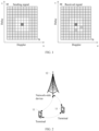
- a transmitting signal includes the following three parts: a single-point pilot at a central location of the lattice point of MxN; a guard interval (with a size of 5 ⁇ 5-1) surrounding the pilot; and data around the guard interval.
- a receive end there are two shift peaks (lattice points filled with slashes in FIG. 1 ) in the guard interval of the lattice point in the delay-Doppler domain, which means that in addition to a primary path, a channel has two secondary paths with different delay Doppler.
- FIG. 1 corresponds to a single-port scenario, that is, only one group of reference signals need to be sent.
- a plurality of pilots are generally mapped to the delay-Doppler plane.
- a transmit end Before transmitting the pilot, a transmit end generally needs to determine a transmitting parameter of the pilot, for example, determining a guard interval of the pilot and the like.
- determining the transmitting parameter of the pilot only based on a delay and Doppler of the channel cannot ensure detection performance of the pilot.
- Embodiments of this application provides methods for transmitting and receiving a pilot and a device, to resolve a problem in the related art that determining a transmitting parameter of the pilot only based on a delay and Doppler of a channel cannot ensure detection performance of the pilot.
- a method for transmitting a pilot including: A transmit end determines a transmitting parameter of the pilot, where the transmitting parameter includes at least one of the following: transmitting power and a guard interval, the transmitting parameter is determined based on first parameters, and the first parameters include a delay, Doppler, and channel quality; and the transmit end transmits the pilot based on the transmitting parameter.
- a method for receiving a pilot including: a receive end receives the pilot, where the pilot is sent by a transmit end based on a transmitting parameter, the transmitting parameter includes at least one of the following: transmitting power and a guard interval, the transmitting parameter is determined based on first parameters, and the first parameters include a delay, Doppler, and channel quality.
- an apparatus for transmitting a pilot including: a determination module, configured to determine a transmitting parameter of the pilot, where the transmitting parameter includes at least one of the following: transmitting power and a guard interval, the transmitting parameter is determined based on first parameters, and the first parameters include a delay, Doppler, and channel quality; and a transmitting module, configured to transmit the pilot based on the transmitting parameter.
- an apparatus for receiving a pilot including: a receiving module, configured to receive the pilot, where the pilot is sent by a transmit end based on a transmitting parameter, the transmitting parameter includes at least one of the following: transmitting power and a guard interval, the transmitting parameter is determined based on first parameters, and the first parameters include a delay, Doppler, and channel quality.
- a terminal includes a processor, a memory, and a program or an instruction that is stored in the memory and executable on the processor.
- the program or the instruction is executed by the processor, the method according to the first aspect or the second aspect is implemented.
- a terminal including: a processor and a communication interface.
- the processor is configured to determine a transmitting parameter of a pilot, where the transmitting parameter includes at least one of the following: transmitting power and a guard interval, the transmitting parameter is determined based on first parameters, and the first parameters include a delay, Doppler, and channel quality.
- the communication interface is configured to transmit the pilot based on the transmitting parameter; or the communication interface is configured to receive the pilot, where the pilot is sent by a transmit end based on the transmitting parameter, the transmitting parameter includes at least one of the following: the transmitting power and the guard interval, the transmitting parameter is determined based on the first parameters, and the first parameters include the delay, the Doppler, and the channel quality.
- a network-side device includes a processor, a memory, and a program or an instruction that is stored in the memory and executable on the processor.
- the program or the instruction is executed by the processor, the method according to the first aspect or the second aspect is implemented.
- a network-side device including a processor and a communication interface.
- the processor is configured to determine a transmitting parameter of a pilot, where the transmitting parameter includes at least one of the following: transmitting power and a guard interval, the transmitting parameter is determined based on first parameters, and the first parameters include a delay, Doppler, and channel quality.
- the communication interface is configured to transmit the pilot based on the transmitting parameter; or the communication interface is configured to receive the pilot, where the pilot is sent by a transmit end based on the transmitting parameter, the transmitting parameter includes at least one of the following: the transmitting power and the guard interval, the transmitting parameter is determined based on the first parameters, and the first parameters include the delay, the Doppler, and the channel quality.
- a readable storage medium stores a program or an instruction.
- the program or the instruction is executed by a processor, the method according to the first aspect or the second aspect is implemented.
- a chip includes a processor and a communication interface.
- the communication interface is coupled to the processor.
- the processor is configured to run a program or an instruction, to implement the method according to the first aspect or the second aspect.
- a computer program/program product is provided.
- the computer program/program product is stored in a storage medium.
- the program/program product is executed by at least one processor to implement the method according to the first aspect or the method in the second aspect.
- a transmit end determines a transmitting parameter of a pilot.
- the transmitting parameter includes transmitting power and/or a guard interval.
- the transmitting parameter is jointly determined based on a delay, Doppler, and channel quality.
- small-scale parameters (a delay and Doppler) and a large-scale parameter (channel quality) of a channel are comprehensively considered to determine the transmitting parameter of the pilot. This helps ensure detection performance of the pilot under various channel conditions and improve communication quality.
- technologies described in the embodiments of this application are not limited to a long term evolution (Long Term Evolution, LTE)/LTE-advanced (LTE-Advanced, LTE-A) system, and may further be used in other wireless communications systems such as code division multiple access (Code Division Multiple Access, CDMA), time division multiple access (Time Division Multiple Access, TDMA), frequency division multiple access (Frequency Division Multiple Access, FDMA), orthogonal frequency division multiple access (Orthogonal Frequency Division Multiple Access, OFDMA), single-carrier frequency-division multiple access (Single-carrier Frequency-Division Multiple Access, SC-FDMA), and another system.
- code division multiple access Code Division Multiple Access
- TDMA time division multiple access
- FDMA frequency division multiple access
- OFDMA Orthogonal frequency division multiple access
- SC-FDMA single-carrier Frequency-Division Multiple Access
- system and “network” in the embodiments of this application may be used interchangeably.
- the described technologies may be applied to both the systems and the radio technologies mentioned above as well as to other systems and radio technologies.
- the following descriptions describe a new radio (New Radio, NR) system for example purposes, and NR terms are used in most of the following descriptions.
- NR New Radio
- 6G 6 th Generation
- FIG. 2 is a schematic diagram of a wireless communication system to which an embodiment of this application can be applied.
- the wireless communication system includes a terminal 11 and a network-side device 12.
- the terminal 11 may also be referred to as a terminal device or user equipment (User Equipment, UE).
- UE User Equipment
- the terminal 11 may be a terminal-side device such as a mobile phone, a tablet personal computer (Tablet Personal Computer), a laptop computer (Laptop Computer) or a notebook computer, a personal digital assistant (Personal Digital Assistant, PDA), a palmtop computer, a netbook, an ultra-mobile personal computer (ultra-mobile personal computer, UMPC), a mobile Internet device (Mobile Internet Device, MID), an augmented reality (augmented reality, AR)/virtual reality (virtual reality, VR) device, a robot, a wearable device (Wearable Device), vehicle user equipment (VUE), pedestrian user equipment (PUE), or a smart household (a household device with a wireless communication function, such as a refrigerator, a television, a washing machine, or furniture).
- a terminal-side device such as a mobile phone, a tablet personal computer (Tablet Personal Computer), a laptop computer (Laptop Computer) or a notebook computer, a personal digital assistant (Personal Digital Assistant, PDA), a palmtop computer,
- the wearable device includes: a smart watch, a smart band, a smart headset, smart glasses, smart jewelry (a smart bracelet, a smart chain bracelet, a smart ring, a smart necklace, a smart anklet, a smart ankle chain, or the like), a smart wrist strap, smart clothes, a game console, and the like. It should be noted that a specific type of the terminal 11 is not limited in the embodiments of this application.
- the network-side device 12 may be a base station or a core network.
- the base station may be referred to as a NodeB, an evolved NodeB, an access point, a base transceiver station (Base Transceiver Station, BTS), a radio base station, a radio transceiver, a basic service set (Basic Service Set, BSS), an extended service set (Extended Service Set, ESS), a NodeB, an evolved NodeB (eNB), a next-generation NodeB (gNB), a home NodeB, a home evolved NodeB, a WLAN access point, a Wi-Fi node, a transmission and reception point (Transmission and Reception Point, TRP), or another appropriate term in the art.
- the base station is not limited to a specified technical term. It should be noted that, in the embodiments of this application, only a base station in an NR system is used as an example, but a specific type of the base station is not limited.
- the embodiments of this application may follow a general principle of power enhancement of the pilot. That is, remaining power on a blank resource element (that is, a guard interval) is used for power enhancement of the pilot. Therefore, when a transmit end needs to enhance power of the pilot, a quantity of blank resource elements may be increased (that is, the guard interval of the pilot is increased) to obtain more remaining power for use on the pilot; or power is borrowed from a data area to enhance the power of the pilot.
- a blank resource element that is, a guard interval
- a quantity of blank resource elements may be increased (that is, the guard interval of the pilot is increased) to obtain more remaining power for use on the pilot; or power is borrowed from a data area to enhance the power of the pilot.
- determination of the guard interval is only related to two small-scale parameters, that is, a delay and Doppler, of a channel.
- channel quality for example, in a specific time length, an average signal-to-noise ratio SNR among several radio frames
- determining the guard interval only based on the delay and the Doppler cannot ensure that detection performance of the pilot is optimal.
- the small-scale parameters and the large-scale parameter of the channel are comprehensively considered to determine a transmitting parameter of the pilot.
- the transmitting parameter for example, may include transmitting power and the guard interval, so as to ensure detection performance of the pilot under various channel conditions.
- a tiered/layered manner for adjusting the guard interval of the pilot is further designed in the embodiments of this application to adjust a period of corresponding signaling according to a change rule of parameters, so as to reduce feedback costs as much as possible.
- pilot/slot in the embodiments of this application may be a same concept, and represents a minimum time-frequency resource unit of a transport block (Transport Block, TB) that carries a complete encoded signal.
- Transport Block Transport Block
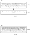
- an embodiment of this application provides a method 300 for transmitting a pilot.
- the method may be performed by a transmit end.
- the method may be performed by software or hardware installed in the transmit end.
- the transmit end may be a terminal or a network-side device. The method includes the following steps.
- the transmit end determines a transmitting parameter of the pilot, where the transmitting parameter includes at least one of the following: transmitting power and a guard interval, the transmitting parameter is determined based on first parameters, and the first parameters include a delay (delay, or referred to as a latency), Doppler, and channel quality.
- the transmitting parameter includes at least one of the following: transmitting power and a guard interval, the transmitting parameter is determined based on first parameters, and the first parameters include a delay (delay, or referred to as a latency), Doppler, and channel quality.
- the parameters for example, the transmitting parameter and the first parameters, mentioned in embodiments of this application may include specific parameter values.
- the channel quality may be a signal-to-noise ratio (Signal-to-Noise Ratio, SNR), a signal to interference and noise ratio (Signal to Interference and Noise Ratio, SINR), a channel quality indicator (Channel Quality Indicator, CQI), or the like, or the channel quality may be obtained by using a bit error rate. Subsequent embodiments use the signal-to-noise ratio as an example to describe the channel quality, and another parameter may also be implemented in a similar manner.
- SNR Signal-to-noise Ratio
- SINR Signal to interference and noise ratio
- CQI Channel Quality Indicator
- the transmit end may be a network-side device, and a receive end may be a terminal; or the transmit end may be a terminal, and the receive end may be a network-side device or another terminal.
- the transmit end may determine the transmitting parameter of the pilot based on indication information from the receive end.
- the indication information may directly indicate the transmitting parameter of the pilot, or the indication information indicates a parameter related to the transmitting parameter of the pilot.
- the transmit end determines the transmitting parameter of the pilot based on the related parameter.
- that the transmit end determines a transmitting parameter of the pilot includes: the transmit end determines the guard interval of the pilot; or the transmit end determines the transmitting power of the pilot, and determines the guard interval of the pilot based on the determined transmitting power; or the transmit end determines the transmitting power of the pilot.
- S304 The transmit end transmits the pilot based on the transmitting parameter.
- the transmit end may map the pilot to a delay-Doppler domain to transmit the pilot to the receive end.
- the transmit end may further indicate the transmitting parameter of the pilot to the receive end, so that the receive end demodulates data.
- the transmit end may indicate a determined transmitting parameter to the terminal by using downlink control information (Downlink Control Information, DCI) or radio resource control (Radio Resource Control, RRC) signaling, so that the terminal demodulates the data.
- DCI Downlink Control Information
- RRC Radio Resource Control
- the transmit end determines the transmitting parameter of the pilot.
- the transmitting parameter includes the transmitting power and/or the guard interval.
- the transmitting parameter is jointly determined based on the delay, the Doppler, and the channel quality.
- small-scale parameters (a delay and Doppler) and a large-scale parameter (channel quality) of a channel are comprehensively considered to determine the transmitting parameter of the pilot. This helps ensure detection performance of the pilot under various channel conditions and improve communication quality.
- the first parameters include the channel quality. That the transmit end determines a transmitting parameter of the pilot includes: The transmit end performs, based on the indication information, at least one of the following: increasing the transmitting power of the pilot, and increasing the guard interval of the pilot.
- the indication information is sent by the receive end when measured channel quality is greater than a first threshold; or the indication information is sent by the receive end when a measured second parameter is greater than or equal to a second threshold, where the second parameter is related to the channel quality.
- the second parameter may be the bit error rate, and the second threshold may be a threshold related to the bit error rate.
- the indication information may include a power amplification multiple of the pilot.
- the transmit end may determine the transmitting parameter of the pilot based on the power amplification multiple. For example, the transmit end increases the transmitting power of the pilot based on the power amplification multiple. For another example, the transmit end increases the guard interval of the pilot based on the power amplification multiple.
- the transmit end may increase the transmitting power of the pilot by increasing the guard interval of the pilot, or may increase the transmitting power of the pilot by reducing transmitting power of the data.
- This process may be referred to as a process in which the pilot borrows power from the data.
- An increased value of the transmitting power of the pilot is equal to a reduced value of the transmitting power of the data, and the data and the pilot are mapped to a same delay-Doppler domain.
- the first threshold may be determined by the receive end based on the foregoing formula.
- that the transmit end determines a transmitting parameter of the pilot may include: The transmit end determines the transmitting parameter of the pilot based on a first transmitting period. A length of the first transmitting period is greater than a length of a second transmitting period.
- the second transmitting period is a period for determining the transmitting parameter of the pilot. For example, the second transmitting period is the period in which the transmit end determines the transmitting parameter of the pilot based on the delay and the Doppler. This embodiment may reduce overheads of feedback signaling as much as possible.
- the foregoing embodiments mainly describe how to determine the transmitting parameter of the pilot based on the channel quality (such as the signal-to-noise ratio).
- the following describes how to determine the transmitting parameter of the pilot based on the delay and the Doppler by using several embodiments.
- the several embodiments described below may be freely combined with the foregoing embodiments.
- the first parameters include the delay and the Doppler.
- the method further includes the following steps.
- the transmit end may determine the transmitting parameter of the pilot based on the delay and the Doppler; or when the transmit end receives the guard interval of the pilot in the foregoing step (5), in S202, the transmit end may directly use the received guard interval as the guard interval of the pilot for transmitting.
- that the transmit end determines a transmitting parameter of the pilot includes: The transmit end determines the transmitting parameter of the pilot based on the second transmitting period.
- the length of the second transmitting period is greater than duration T.
- the duration T may be a length of one slot/subframe, so as to reduce the overheads of the feedback signaling as much as possible.
- the transmit end determines the transmitting parameter of the pilot based on the second transmitting period. Certainly, if the transmit end receives a third parameter in the second transmitting period, the transmit end determines the transmitting parameter of the pilot based on the third parameter.
- the third parameter is sent by the receive end when the second parameter is greater than or equal to the second threshold.
- the third parameter may be the guard interval.
- the second parameter is related to the channel quality.
- the second parameter may be the bit error rate, and the second threshold may be the threshold related to the bit error rate.
- This embodiment may break through the original second transmitting period. For example, in a feedback period (the second transmitting period), if a bit error rate ⁇ of a subframe k or bit error rates of consecutive g subframes starting from k meet ⁇ _threshold, the receive end immediately feeds back a new guard interval and indicates the guard interval to the transmit end, so that the transmit end adjusts the guard interval of the pilot in real time.
- a start location of periodic feedback is recalculated from a subframe obtained through adjustment, that is, from a (k+1)-th subframe or a (k+g+1)-th subframe.
- that the transmit end determines a transmitting parameter of the pilot includes: The transmit end increases the transmitting power of the pilot; or the transmit end reduces the transmitting power of the pilot.
- the transmit end increases the transmitting power of the pilot
- the increased value of the transmitting power of the pilot is equal to the reduced value of the transmitting power of the data
- the data and the pilot are mapped to the same delay-Doppler domain, that is, the pilot borrows power from the data.
- the example may further include the following step:
- the transmit end indicates the transmitting power of the data to the receive end, so that the receive end demodulates the data.
- the transmit end determines a transmitting parameter of the pilot includes: The transmit end determines the transmitting power of the pilot based on a power scaling coefficient, where the power scaling coefficient is selected by the receive end from a plurality of default power scaling coefficients, to reduce feedback overheads.
- that the transmit end determines the transmitting power of the pilot based on a power scaling coefficient includes: When the power scaling coefficient is greater than 1, the transmit end increases the transmitting power of the pilot based on one of the following:
- that the transmit end determines the transmitting power of the pilot based on a power scaling coefficient includes: When the power scaling coefficient is less than 1, the transmit end reduces the transmitting power of the pilot.
- the example may further include the following step:
- the transmit end increases the transmitting power of the data.
- a reduced value of the transmitting power of the pilot is equal to an increased value of the transmitting power of the data, and the data and the pilot are mapped to the same delay-Doppler domain.
- the method for transmitting a pilot according to this embodiment of this application is described in detail above with reference to FIG. 3 .
- a method for receiving a pilot according to another embodiment of this application is described in detail below with reference to FIG. 4 . It may be understood that interaction between a receive end and a transmit end described from the perspective of the receive end is the same as that described on a transmit end side in the method shown in FIG. 3 . To avoid repetition, related descriptions are appropriately omitted.
- FIG. 4 is a schematic flowchart for implementing a method for receiving a pilot according to an embodiment of this application. The method may be applied to a receive end. As shown in FIG. 4 , a method 400 includes the following steps.
- the receive end receives the pilot, where the pilot is sent by a transmit end based on a transmitting parameter, the transmitting parameter includes at least one of the following: transmitting power and a guard interval, the transmitting parameter is determined based on first parameters, and the first parameters include a delay, Doppler, and channel quality.
- the receive end receives the pilot.
- the pilot is sent by the transmit end based on the transmitting parameter.
- the transmitting parameter includes the transmitting power and/or the guard interval.
- the transmitting parameter is jointly determined based on the delay, the Doppler, and the channel quality.
- small-scale parameters (a delay and Doppler) and a large-scale parameter (channel quality) of a channel are comprehensively considered to determine the transmitting parameter of the pilot. This helps ensure detection performance of the pilot under various channel conditions and improve communication quality.
- the first parameters include the channel quality.
- the method further includes: The receive end transmits indication information when measured channel quality is greater than a first threshold; or the receive end transmits indication information when a measured second parameter is greater than or equal to a second threshold, where the second parameter is related to the channel quality.
- the indication information is used by the transmit end to perform at least one of the following: increasing the transmitting power of the pilot, and increasing the guard interval of the pilot.
- the indication information includes a power amplification multiple of the pilot.
- the transmit end is configured to determine the transmitting parameter of the pilot based on a first transmitting period.
- a length of the first transmitting period is greater than a length of a second transmitting period.
- the second transmitting period is a period in which the transmit end determines the transmitting parameter of the pilot based on the delay and the Doppler.
- the first parameters include the delay and the Doppler.
- the method further includes: The receive end receives a first pilot.
- the receive end transmits a maximum delay and maximum Doppler.
- the maximum delay and the maximum Doppler are determined by the receive end based on the first pilot, and the maximum delay and the maximum Doppler are used by the transmit end to determine a transmitting parameter of a second pilot.
- the receive end receives the second pilot, where the second pilot is sent by the transmit end based on the transmitting parameter of the second pilot.
- the receive end transmits the delay and the Doppler, where the delay and the Doppler are determined by the receive end based on the second pilot; or the receive end transmits the guard interval of the pilot, where the guard interval is determined by the receive end based on the second pilot.
- the transmit end is configured to determine the transmitting parameter of the pilot based on the second transmitting period.
- the length of the second transmitting period is greater than duration T.
- the method further includes: The receive end transmits a third parameter when the second parameter is greater than or equal to the second threshold.
- the second parameter is related to the channel quality. If the transmit end receives the third parameter in the second transmitting period, the transmit end is further configured to determine the transmitting parameter of the pilot based on the third parameter.
- the transmit end is configured to increase the transmitting power of the pilot, or reduce the transmitting power of the pilot.
- an increased value of the transmitting power of the pilot is equal to a reduced value of transmitting power of data, and the data and the pilot are mapped to a same delay-Doppler domain.
- the method further includes: The receive end receives the transmitting power of the data.
- the receive end demodulates the data based on the transmitting power of the data.
- the method further includes: The receive end selects a power scaling coefficient from a plurality of default power scaling coefficients, where the power scaling coefficient is used by the transmit end to determine the transmitting power of the pilot.
- Embodiment 1 provides a process in which a transmit end performs, based on feedback of a receive end, two tiers of dynamic adjustment on a pilot transmitting mode. This embodiment may be performed in two tiers, that is a first tier (Tier 1) and a second tier (Tier 2).
- the transmit end may obtain prior information of channel state information (Channel State Information, CSI).
- CSI Channel State Information
- the transmit end may transmit an initial pilot subframe (corresponding to the first pilot in the foregoing embodiments). It is assumed that a number is 0.
- An initial pilot frame has a small quantity of sampling points (that is, MN is small, where the MN may be a size of a lattice point of a delay-Doppler domain) to reduce overheads, and a data part is not included, so that a sufficient guard interval is ensured to roughly estimate a maximum delay ⁇ max and maximum Doppler ⁇ max of a channel.
- a set of the maximum delay and maximum Doppler estimated by the receive end by using the initial pilot frame is denoted as ( ⁇ m 0 , ⁇ m 0 ), and is fed back to the transmit end.
- the transmit end determines a guard interval of a pilot of a next frame based on this set ( ⁇ m 0 , ⁇ m 0 ).
- the transmit end transmits the pilot (corresponding to the second pilot in the foregoing embodiments) in a next subframe, that is, a frame with a number of 1.
- the guard interval of the pilot may be determined by ( ⁇ m 0 , ⁇ m 0 ).
- the receive end After receiving the subframe 1, the receive end obtains a delay and Doppler ( ⁇ m 1 , ⁇ m 1 ) through measurement, and feeds back measured ( ⁇ m 1 , ⁇ m 1 ) to the transmit end.
- a width that is of the guard interval of the pilot and that is quantized by the subframe 1 based on resolution of a delay-Doppler resource block is ( l ⁇ 0 , k ⁇ 0 ).
- the receive end calculates an updated width ( l ⁇ 1 , k ⁇ 1 ) of the guard interval of the pilot by using a pilot measurement result of the subframe 1, and directly feeds back ( l ⁇ 1 , k ⁇ 1 ) or ( l ⁇ 1 ⁇ l ⁇ 0 , k ⁇ 1 ⁇ k ⁇ 0 ) instead of ( ⁇ m 1 , ⁇ m 1 ). Because the former is an integer, and the latter is a floating point number, a part of feedback overheads may be reduced.
- the transmit end does not need to perform subframe-level feedback and update of (l ⁇ ,k ⁇ ), and may perform feedback based on a first period T 1 (corresponding to the second transmitting period in the foregoing embodiments).
- a bit error rate ⁇ may further be introduced as a basis for determining whether it is required to break the period to perform feedback in real time.
- ⁇ threshold represents a threshold of the bit error rate
- the receive end immediately performs feedback, so that the transmit end adjusts the guard interval of the pilot in real time.
- a start location of periodic feedback is recalculated from a subframe obtained through adjustment, that is, from a (k+1)-th subframe or a (k+g+1)-th subframe.
- T 2 may further be used as a second period to adjust the pilot transmitting mode based on the SNR.
- c and K are known constants, and L and corresponding h l are given based on a channel estimation result of the pilot.
- this may be achieved by increasing a transmitting power multiple c of the pilot, for example, by increasing the guard interval of the pilot.
- the transmit end may correspondingly adjust a set of values (l ⁇ ,k ⁇ ) of the guard interval of the pilot, to meet that a range of the values is greater than c new .
- the guard interval needs to be indicated to the receive end by the transmit end in DCI or RRC signaling.
- Embodiment 2 An architecture of Embodiment 2 is similar to that of Embodiment 1. A similarity lies in that an architecture having two tiers is still used. A difference lies in that, in a pilot transmitting mode in Embodiment 2, transmitting power of a pilot and a guard interval of the pilot are decoupled, that is, a transmitting power multiple of the pilot meets c ⁇ (2l ⁇ +l)(4k ⁇ +1), where (2l ⁇ +1)(4k ⁇ +1) represents a size of the guard interval of the pilot. Therefore, in this embodiment, the guard interval of the pilot is estimated and determined by using small-scale parameters of Tier 1, and the transmitting power of the pilot is estimated and determined by using a large-scale parameter of Tier 2. This embodiment may be performed in two tiers, that is a first tier (Tier 1) and a second tier (Tier 2).
- Tier 1 For Tier 1, refer to Embodiment 1. To avoid repetition, the description of Tier 1 is omitted.
- the guard interval and the transmitting power multiple may be indicated to a receive end by a transmit end in DCI or RRC signaling.
- T 2 further needs to be used as a second period to adjust the transmitting power of the pilot based on the SNR.
- K is a known constant, and L and corresponding h l are given based on a channel estimation result of the pilot.
- c indicated by the transmit end is used, so that a specific value may be calculated.
- this is achieved by increasing the transmitting power multiple c of the pilot and by increasing the guard interval of the pilot based on the increased transmitting power multiple of the pilot.
- the transmit end may correspondingly adjust the transmitting power of the pilot to c'p 0 , c' ⁇ c new .
- Embodiment 3 An architecture of Embodiment 3 is similar to that of Embodiment 2. A difference lies in that, in the pilot transmitting mode in Embodiment 2, the receive end may indicate the guard interval (l ⁇ ,k ⁇ ) of the pilot and the transmitting power multiple c of the pilot, but in Embodiment 3, the receive end may only indicate the guard interval (l ⁇ ,k ⁇ ) of the pilot, and does not need to indicate the transmitting power multiple c of the pilot.
- This embodiment may be performed in two tiers, that is a first tier (Tier 1) and a second tier (Tier 2).
- Tier 1 For Tier 1, refer to Embodiment 1. To avoid repetition, the description of Tier 1 is omitted.
- the transmit end adjusts c based on a step length preset according to a protocol.
- Embodiment 4 a process for dynamically adjusting a pilot transmitting mode is simplified. Compared with Embodiment 1, Embodiment 4 is performed in one tier instead of two tiers.
- a transmit end may obtain prior information of CSI.
- the transmit end may transmit an initial pilot subframe (corresponding to the first pilot in the foregoing embodiments). It is assumed that a number is 0.
- An initial pilot frame has a small quantity of sampling points (that is, MN is small) to reduce overheads, and a data part is not included, so that a sufficient guard interval is ensured to roughly estimate a maximum delay ⁇ max and maximum Doppler ⁇ max of a channel.
- a set of the maximum delay and maximum Doppler estimated by a receive end by using the initial pilot frame is denoted as ( ⁇ m 0 , ⁇ m 0 ), and is fed back to the transmit end.
- the transmit end determines a guard interval of a pilot of a next frame based on this set ( ⁇ m 0 , ⁇ m 0 ).
- the transmit end transmits the pilot (corresponding to the second pilot in the foregoing embodiments) in a next subframe, that is, a frame with a number of 1.
- the guard interval of the pilot may be determined by ( ⁇ m 0 , ⁇ m 0 ).
- the receive end After receiving the subframe 1, the receive end obtains ( ⁇ m 1 , ⁇ m 1 ) through measurement, and feeds back measured ( ⁇ m 1 , ⁇ m 1 ) to the transmit end.
- a width that is of the guard interval of the pilot and that is quantized by the subframe 1 based on resolution of a delay-Doppler resource block is ( l ⁇ 0 , k ⁇ 0 ).
- the receive end calculates an updated width ( l ⁇ 1 , k ⁇ 1 ) of the guard interval of the pilot by using a pilot measurement result of the subframe 1, and directly feeds back ( l ⁇ 1 , k ⁇ 1 ) or ( l ⁇ 1 ⁇ l ⁇ 0 , k ⁇ 1 ⁇ k ⁇ 0 ) instead of ( ⁇ m 1 , ⁇ m 1 ). Because the former is an integer, and the latter is a floating point number, a part of feedback overheads may be reduced.
- the transmit end does not need to perform subframe-level feedback and update of ( l ⁇ , k ⁇ ), and may perform feedback based on a first period T 1 (corresponding to the second transmitting period in the foregoing embodiments).
- This embodiment may be a supplementary solution, and may be combined with any one of the foregoing four embodiments.
- a procedure may be: A network-side device determines the guard interval based on channel characteristics ( ⁇ max and ⁇ max ) obtained by a terminal through estimation, and remains the guard interval unchanged. If the power borrowed from the guard interval still does not meet a requirement on the power of the pilot, the power is borrowed from a data area. In this case, a magnitude (an absolute value or a relative value) of the power of the data area needs to be notified to a receive end to assist in demodulating the data.
- a value of f may be ⁇ 0.8, 1, 1.2, 1.4 ⁇ or ⁇ 1, 1.5, 2, 4 ⁇ .
- the network-side device may select to remain the guard interval reported by the receive end unchanged, and borrow the power from the data (f>1); or the network-side device may increase the guard interval, and does not borrow the power from the data (f>1); or the network-side device may relatively increase the power of the data (f ⁇ 1). In all the manners, a new guard interval or a magnitude of the power borrowed from the data may both be notified to the receive end.
- the methods for transmitting and receiving a pilot provided in the embodiments of this application may be performed by apparatuses for transmitting and receiving a pilot or by control modules that are in the apparatuses for transmitting and receiving a pilot and that are configured to perform the methods for transmitting and receiving a pilot.
- apparatuses for transmitting and receiving a pilot perform the methods for transmitting and receiving a pilot is used to describe the apparatuses for transmitting and receiving a pilot provided in this embodiment of this application.
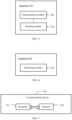
- FIG. 5 is a schematic diagram of a structure of an apparatus for transmitting a pilot according to an embodiment of this application.
- the apparatus may correspond to a transmit end in other embodiments.
- an apparatus 500 includes the following modules.
- a determination module 502 may be configured to determine a transmitting parameter of the pilot, where the transmitting parameter includes at least one of the following: transmitting power and a guard interval, the transmitting parameter is determined based on first parameters, and the first parameters include a delay, Doppler, and channel quality.
- a transmitting module 504 may be configured to transmit the pilot based on the transmitting parameter.
- the apparatus 500 determines the transmitting parameter of the pilot.
- the transmitting parameter includes the transmitting power and/or the guard interval.
- the transmitting parameter is jointly determined based on the delay, the Doppler, and the channel quality.
- small-scale parameters (a delay and Doppler) and a large-scale parameter (channel quality) of a channel are comprehensively considered to determine the transmitting parameter of the pilot. This helps ensure detection performance of the pilot under various channel conditions and improve communication quality.
- the first parameters include the channel quality.
- the determination module 502 is configured to perform, based on indication information, at least one of the following: increasing the transmitting power of the pilot, and increasing the guard interval of the pilot.
- the indication information is sent by a receive end when measured channel quality is greater than a first threshold; or the indication information is sent by the receive end when a measured second parameter is greater than or equal to a second threshold, where the second parameter is related to the channel quality.
- the indication information includes a power amplification multiple of the pilot.
- the determination module 502 may be configured to determine the transmitting parameter of the pilot based on a first transmitting period.
- a length of the first transmitting period is greater than a length of a second transmitting period.
- the second transmitting period is a period for determining the transmitting parameter of the pilot.
- the first parameters include the delay and the Doppler.
- the transmitting module 504 may be configured to transmit a first pilot.
- the apparatus further includes a receiving module for receiving a maximum delay and maximum Doppler.
- the maximum delay and the maximum Doppler are determined by the receive end based on the first pilot.
- the determination module 502 may be configured to determine a transmitting parameter of a second pilot based on the maximum delay and the maximum Doppler.
- the transmitting module 504 may be configured to transmit the second pilot based on the transmitting parameter of the second pilot.
- the receiving module may be configured to receive the delay and the Doppler, where the delay and the Doppler are determined by the receive end based on the second pilot; or the receiving module may be configured to receive the guard interval of the pilot, where the guard interval is determined by the receive end based on the second pilot.
- the determination module 502 may be configured to determine the transmitting parameter of the pilot based on the second transmitting period.
- the length of the second transmitting period is greater than duration T.
- the determination module 502 may be configured to: if the apparatus receives a third parameter in the second transmitting period, determine the transmitting parameter of the pilot based on the third parameter, where the third parameter is sent by the receive end when the second parameter is greater than or equal to the second threshold, and the second parameter is related to the channel quality.
- the determination module 502 may be configured to increase the transmitting power of the pilot, or reduce the transmitting power of the pilot.
- an increased value of the transmitting power of the pilot is equal to a reduced value of transmitting power of data, and the data and the pilot are mapped to a same delay-Doppler domain.
- the transmitting module 504 may be configured to indicate the transmitting power of the data to the receive end, so that the receive end demodulates the data.
- the determination module 502 may be configured to determine the transmitting power of the pilot based on a power scaling coefficient, where the power scaling coefficient is selected by the receive end from a plurality of default power scaling coefficients.
- the determination module 502 may be configured to increase, when the power scaling coefficient is greater than 1, the transmitting power of the pilot based on one of the following: (1) increasing the guard interval of the pilot, where the transmitting power of the pilot is coupled to the guard interval of the pilot; and (2) reducing the transmitting power of the data, where the data and the pilot are mapped to the same delay-Doppler domain.
- the determination module 502 may be configured to reduce the transmitting power of the pilot when the power scaling coefficient is less than 1.
- the determination module 502 may be configured to increase the transmitting power of the data.
- a reduced value of the transmitting power of the pilot is equal to an increased value of the transmitting power of the data, and the data and the pilot are mapped to the same delay-Doppler domain.
- the transmitting module 504 may be configured to indicate the transmitting parameter of the pilot to the receive end.
- the apparatus 500 according to this embodiment of this application may correspond to the procedures of the method 200 in the embodiment of this application, and units/modules in the apparatus 500 and the foregoing other operations and/or functions are separately for implementing the corresponding procedures in the method 200, and can achieve a same or equivalent technical effect. For brevity, details are not described herein again.
- the apparatuses for transmitting and receiving a pilot in the embodiments of this application may be apparatuses, apparatuses or electronic devices with an operating system, or components, integrated circuits, or chips in a terminal.
- the apparatus or electronic device may be a mobile terminal, or a non-mobile terminal.
- the mobile terminal may include but is not limited to the foregoing listed types of a terminal 11.
- the non-mobile terminal may be a server, a network attached storage (Network Attached Storage, NAS), a personal computer (personal computer, PC), a television (television, TV), a teller machine, a self-service machine, or the like. This is not specifically limited in the embodiments of this application.
- the apparatuses for transmitting and receiving a pilot provided in the embodiments of this application can implement the processes implemented in method embodiments from FIG. 2 to FIG. 3 , and achieve a same technical effect. To avoid repetition, details are not described herein again.
- FIG. 6 is a schematic diagram of a structure of an apparatus for receiving a pilot according to an embodiment of this application.
- the apparatus may correspond to a receive end in other embodiments.
- an apparatus 600 includes the following modules.
- a receiving module 602 may be configured to receive the pilot, where the pilot is sent by a transmit end based on a transmitting parameter, the transmitting parameter includes at least one of the following: transmitting power and a guard interval, the transmitting parameter is determined based on first parameters, and the first parameters include a delay, Doppler, and channel quality.
- the apparatus 600 receives the pilot.
- the pilot is sent by the transmit end based on the transmitting parameter.
- the transmitting parameter includes the transmitting power and/or the guard interval.
- the transmitting parameter is jointly determined based on the delay, the Doppler, and the channel quality.
- small-scale parameters (a delay and Doppler) and a large-scale parameter (channel quality) of a channel are comprehensively considered to determine the transmitting parameter of the pilot. This helps ensure detection performance of the pilot under various channel conditions and improve communication quality.
- the first parameters include the channel quality.
- the apparatus further includes a receiving module configured to transmit indication information when measured channel quality is greater than a first threshold; or transmitting indication information when a measured second parameter is greater than or equal to a second threshold, where the second parameter is related to the channel quality.
- the indication information is used to perform at least one of the following: increasing the transmitting power of the pilot, and increasing the guard interval of the pilot.
- the indication information includes a power amplification multiple of the pilot.
- the transmit end is configured to determine the transmitting parameter of the pilot based on a first transmitting period.
- a length of the first transmitting period is greater than a length of a second transmitting period.
- the second transmitting period is a period in which the transmit end determines the transmitting parameter of the pilot based on the delay and the Doppler.
- the first parameters include the delay and the Doppler.
- the receiving module 602 may be configured to receive a first pilot.
- the apparatus further includes a transmitting module configured to transmit a maximum delay and maximum Doppler.
- the maximum delay and the maximum Doppler are determined by the apparatus based on the first pilot, and the maximum delay and the maximum Doppler are used by the transmit end to determine a transmitting parameter of a second pilot.
- the receiving module 602 may be configured to receive the second pilot, where the second pilot is sent by the transmit end based on the transmitting parameter of the second pilot.
- the transmitting module is configured to transmit the delay and the Doppler, where the delay and the Doppler are determined by the apparatus based on the second pilot; or the transmitting module is configured to transmit the guard interval of the pilot, where the guard interval is determined by the apparatus based on the second pilot.
- the transmit end is configured to determine the transmitting parameter of the pilot based on the second transmitting period.
- the length of the second transmitting period is greater than duration T.
- the apparatus further includes the transmitting module configured to transmit a third parameter when the second parameter is greater than or equal to the second threshold.
- the second parameter is related to the channel quality. If the transmit end receives the third parameter in the second transmitting period, the transmit end is further configured to determine the transmitting parameter of the pilot based on the third parameter.
- the transmit end is configured to increase the transmitting power of the pilot, or reduce the transmitting power of the pilot.
- an increased value of the transmitting power of the pilot is equal to a reduced value of transmitting power of data, and the data and the pilot are mapped to a same delay-Doppler domain.
- the receiving module 602 may be configured to: receive the transmitting power of the data; and demodulate the data based on the transmitting power of the data.
- the apparatus further includes a selection module for selecting a power scaling coefficient from a plurality of default power scaling coefficients, where the power scaling coefficient is used by the transmit end to determine the transmitting power of the pilot.
- the apparatus 600 may correspond to the procedures of the method 300 in the embodiment of this application, and units/modules in the apparatus 600 and the foregoing operations and/or functions are separately for implementing the corresponding procedures of the method 300, and can achieve a same or equivalent technical effect. For brevity, details are not described herein again.
- an embodiment of this application further provides a communication device 700, including a processor 701, a memory 702, and a program or an instruction that is stored in the memory 702 and executable on the processor 701.
- a communication device 700 including a processor 701, a memory 702, and a program or an instruction that is stored in the memory 702 and executable on the processor 701.
- the communication device 700 is a terminal
- the program or the instruction is executed by the processor 701
- the processes of the foregoing embodiments of the methods for transmitting and receiving a pilot are implemented, and a same technical effect can be achieved.
- the communication device 700 is a network-side device, when the program or the instruction is executed by the processor 701, the processes in the foregoing embodiments of the methods for transmitting and receiving a pilot are implemented, and a same technical effect can be achieved.
- details are not described herein again.
- An embodiment of this application further provides a terminal, including: a processor and a communication interface.
- the processor is configured to determine a transmitting parameter of a pilot, where the transmitting parameter includes at least one of the following: transmitting power and a guard interval, the transmitting parameter is determined based on first parameters, and the first parameters include a delay, Doppler, and channel quality.
- the communication interface is configured to transmit the pilot based on the transmitting parameter; or the communication interface is configured to receive the pilot, where the pilot is sent by a transmit end based on the transmitting parameter, the transmitting parameter includes at least one of the following: the transmitting power and the guard interval, the transmitting parameter is determined based on the first parameters, and the first parameters include the delay, the Doppler, and the channel quality.
- FIG. 8 is a schematic diagram of a hardware structure of a terminal according to an embodiment of this application.
- a terminal 800 includes but is not limited to at least a part of components such as a radio frequency unit 801, a network module 802, an audio output unit 803, an input unit 804, a sensor 805, a display unit 806, a user input unit 807, an interface unit 808, a memory 809, and a processor 810.
- the terminal 800 may further include a power supply (such as a battery) that supplies power to the components.
- the power supply may be logically connected to the processor 810 by using a power supply management system, to implement functions such as charging and discharging management and power consumption management by using the power supply management system.
- the terminal structure shown in FIG. 8 constitutes no limitation on the terminal, and the terminal may include more or fewer components than those shown in the figure, or combine some components, or have different component arrangements. Details are not described herein.
- the input unit 804 may include a graphics processing unit (Graphics Processing Unit, GPU) 8041 and a microphone 8042.
- the graphics processing unit 8041 processes image data of a static picture or a video obtained by an image capture apparatus (for example, a camera) in a video capture mode or an image capture mode.
- the display unit 806 may include a display panel 8061.
- the display panel 8061 may be configured in a form such as a liquid crystal display or an organic light-emitting diode.
- the user input unit 807 includes a touch panel 8071 and another input device 8072.
- the touch panel 8071 is also referred to as a touchscreen.
- the touch panel 8071 may include two parts: a touch detection apparatus and a touch controller.
- the another input device 8072 may include but is not limited to a physical keyboard, a functional button (such as a volume control button or a power on/off button), a trackball, a mouse, and a joystick. Details are not described herein.
- the radio frequency unit 801 receives downlink data from a network side-device and then transmits the downlink data to the processor 810 for processing; and transmits uplink data to the network-side device.
- the radio frequency unit 801 includes but is not limited to an antenna, at least one amplifier, a transceiver, a coupler, a low noise amplifier, a duplexer, and the like.
- the memory 809 may be configured to store a software program or an instruction and various data.
- the memory 809 may mainly include a program or instruction storage area and a data storage area.
- the program or instruction storage area may store an operating system, an application or an instruction required by at least one function (for example, a sound playing function or an image playing function), and the like.
- the memory 809 may include a high-speed random access memory, and may further include a non-transient memory.
- the non-transient memory may be a read-only memory (Read-Only Memory, ROM), a programmable read-only memory (Programmable ROM, PROM), an erasable programmable read-only memory (Erasable PROM, EPROM), an electrically erasable programmable read-only memory (Electrically EPROM, EEPROM), or a flash memory, for example, at least one disk storage device, a flash memory device, or another non-transient solid-state storage device.
- ROM Read-Only Memory
- PROM programmable read-only memory
- Erasable PROM Erasable PROM
- EPROM electrically erasable programmable read-only memory
- EEPROM electrically erasable programmable read-only memory
- flash memory for example, at least one disk storage device, a flash memory device, or another non-transient solid-state storage device.
- the processor 810 may include one or more processing units.
- an application processor and a modem processor may be integrated into the processor 810.
- the application processor mainly processes an operating system, a user interface, an application, an instruction, or the like.
- the modem processor mainly processes wireless communication, for example, a baseband processor. It may be understood that, alternatively, the modem processor may not be integrated into the processor 810.
- the processor 810 may be configured to determine a transmitting parameter of a pilot, where the transmitting parameter includes at least one of the following: transmitting power and a guard interval, the transmitting parameter is determined based on first parameters, and the first parameters include a delay, Doppler, and channel quality.
- the radio frequency unit 801 may be configured to transmit the pilot based on the transmitting parameter; or the radio frequency unit 801 may be configured to receive the pilot, where the pilot is sent by a transmit end based on the transmitting parameter, the transmitting parameter includes at least one of the following: the transmitting power and the guard interval, the transmitting parameter is determined based on the first parameters, and the first parameters include the delay, the Doppler, and the channel quality.
- the transmitting parameter of the pilot includes the transmitting power and/or the guard interval.
- the transmitting parameter is jointly determined based on the delay, the Doppler, and the channel quality.
- small-scale parameters (a delay and Doppler) and a large-scale parameter (channel quality) of a channel are comprehensively considered to determine the transmitting parameter of the pilot. This helps ensure detection performance of the pilot under various channel conditions and improve communication quality.
- the terminal 800 provided in this embodiment of this application may further implement the processes of the foregoing embodiments of the methods for transmitting and receiving a pilot, and a same technical effect can be achieved. To avoid repetition, details are not described herein again.
- An embodiment of this application further provides a network-side device, including a processor and a communication interface.
- the processor is configured to determine a transmitting parameter of a pilot, where the transmitting parameter includes at least one of the following: transmitting power and a guard interval, the transmitting parameter is determined based on first parameters, and the first parameters include a delay, Doppler, and channel quality.
- the communication interface is configured to transmit the pilot based on the transmitting parameter; or the communication interface is configured to receive the pilot, where the pilot is sent by a transmit end based on the transmitting parameter, the transmitting parameter includes at least one of the following: the transmitting power and the guard interval, the transmitting parameter is determined based on the first parameters, and the first parameters include the delay, the Doppler, and the channel quality.
- the network-side device embodiment corresponds to the foregoing method embodiment of the network-side device. Each implementation process and implementation of the foregoing method embodiment may be applicable to the network-side device embodiment, and can achieve a same technical effect.
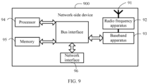
- a network-side device 900 includes an antenna 91, a radio frequency apparatus 92, and a baseband apparatus 93.
- the antenna 91 is connected to the radio frequency apparatus 92.
- the radio frequency apparatus 92 receives information through the antenna 91, and transmits the received information to the baseband apparatus 93 for processing.
- the baseband apparatus 93 processes information that needs to be sent, and transmits processed information to the radio frequency apparatus 92.
- the radio frequency apparatus 92 processes the received information, and transmits processed information through the antenna 91.
- the frequency band processing apparatus may be located in the baseband apparatus 93.
- the method performed by the network-side device in the foregoing embodiment may be implemented in the baseband apparatus 93.
- the baseband apparatus 93 includes a processor 94 and a memory 95.
- the baseband apparatus 93 may include, for example, at least one baseband board, where a plurality of chips are disposed on the baseband board. As shown in FIG. 9 , one chip is, for example, the processor 94, which is connected to the memory 95, to invoke a program in the memory 95 to perform operations of the network-side device shown in the foregoing method embodiment.
- the baseband apparatus 93 may further include a network interface 96 configured to exchange information with the radio frequency apparatus 92.
- the interface is a common public radio interface (common public radio interface, CPRI for short).
- the network-side device in this embodiment of this application further includes an instruction or a program that is stored in the memory 95 and executable on the processor 94.
- the processor 94 invokes the instruction or the program in the memory 95 to perform the method performed by the modules shown in FIG. 5 and FIG. 6 , and a same technical effect is achieved. To avoid repetition, details are not described herein again.
- An embodiment of this application further provides a readable storage medium.
- the readable storage medium stores a program or an instruction.
- the processes of the foregoing embodiments of the methods for transmitting and receiving a pilot are implemented, and a same technical effect can be achieved. To avoid repetition, details are not described herein again.
- the processor may be the processor in the terminal described in the foregoing embodiment.
- the readable storage medium includes a computer-readable storage medium, such as a computer read-only memory (Read-Only Memory, ROM), a random access memory (Random Access Memory, RAM), a magnetic disk, or an optical disc.
- An embodiment of this application further provides a chip.
- the chip includes a processor and a communication interface.
- the communication interface is coupled to the processor, and the processor is configured to run a program or an instruction to implement the processes of the foregoing embodiments of the methods for transmitting and receiving a pilot, and a same technical effect can be achieved. To avoid repetition, details are not described herein again.
- the chip mentioned in this embodiment of this application may also be called a system-level chip, a system chip, a chip system, a system on chip, or the like.
- An embodiment of this application further provides a computer program product.
- the computer program product is stored in a nonvolatile storage medium.
- the computer program product is executed by at least one processor to implement the processes of foregoing embodiments of the methods for transmitting and receiving a pilot, and a same technical effect can be achieved. To avoid repetition, details are not described herein again.
- An embodiment of this application further provides a communication device configured to perform the processes of the foregoing embodiments of pilot transmitting and receiving, and a same technical effect can be achieved. To avoid repetition, details are not described herein again.
- the computer software product is stored in a storage medium (for example, a ROM/RAM, a magnetic disk, or an optical disc), and includes several instructions for instructing a terminal (which may be a mobile phone, a computer, a server, an air conditioner, a network-side device, or the like) to perform the methods described in the embodiments of this application.
- a storage medium for example, a ROM/RAM, a magnetic disk, or an optical disc
Landscapes
- Engineering & Computer Science (AREA)
- Signal Processing (AREA)
- Computer Networks & Wireless Communication (AREA)
- Quality & Reliability (AREA)
- Power Engineering (AREA)
- Mobile Radio Communication Systems (AREA)
Applications Claiming Priority (2)
| Application Number | Priority Date | Filing Date | Title |
|---|---|---|---|
| CN202111039470.5A CN115776359A (zh) | 2021-09-06 | 2021-09-06 | 导频的发送、接收方法和设备 |
| PCT/CN2022/116477 WO2023030438A1 (zh) | 2021-09-06 | 2022-09-01 | 导频的发送、接收方法和设备 |
Publications (2)
| Publication Number | Publication Date |
|---|---|
| EP4401348A1 true EP4401348A1 (de) | 2024-07-17 |
| EP4401348A4 EP4401348A4 (de) | 2025-01-15 |
Family
ID=85387420
Family Applications (1)
| Application Number | Title | Priority Date | Filing Date |
|---|---|---|---|
| EP22863573.6A Pending EP4401348A4 (de) | 2021-09-06 | 2022-09-01 | Pilotfrequenzsende- und empfangsverfahren und -vorrichtung |
Country Status (4)
| Country | Link |
|---|---|
| US (1) | US20240214145A1 (de) |
| EP (1) | EP4401348A4 (de) |
| CN (1) | CN115776359A (de) |
| WO (1) | WO2023030438A1 (de) |
Families Citing this family (3)
| Publication number | Priority date | Publication date | Assignee | Title |
|---|---|---|---|---|
| US20250126578A1 (en) * | 2023-10-17 | 2025-04-17 | Samsung Electronics Company, Ltd. | Systems and Methods for Multiple Access Based on Controlling Transmit Power of Multiple Transmit Antennas |
| WO2025086231A1 (zh) * | 2023-10-26 | 2025-05-01 | 北京小米移动软件有限公司 | 信息传输方法、终端、网络设备 |
| CN120075015A (zh) * | 2025-02-25 | 2025-05-30 | 重庆邮电大学 | 一种速率自适应的短波otfs通探一体化传输方法 |
Family Cites Families (12)
| Publication number | Priority date | Publication date | Assignee | Title |
|---|---|---|---|---|
| JP5078610B2 (ja) * | 2005-05-26 | 2012-11-21 | パナソニック株式会社 | 無線通信装置および無線通信方法 |
| US8626223B2 (en) * | 2008-05-07 | 2014-01-07 | At&T Mobility Ii Llc | Femto cell signaling gating |
| US8718021B2 (en) * | 2008-07-07 | 2014-05-06 | Apple Inc. | Uplink control signal design for wireless system |
| CN102077657B (zh) * | 2009-05-21 | 2013-04-24 | 华为技术有限公司 | 一种功率控制方法、装置和基站 |
| EP3105875B1 (de) * | 2014-02-10 | 2020-05-13 | Telefonaktiebolaget LM Ericsson (publ) | Kopplung von referenzsignalen in einem drahtlosen netzwerk |
| EP3419201A1 (de) * | 2014-06-24 | 2018-12-26 | Huawei Technologies Co., Ltd. | Verfahren und vorrichtung für mehrfachzugriff in einem drahtloskommunikationssystem |
| CN108702271B (zh) * | 2016-02-26 | 2021-02-23 | 杜塞尔多夫华为技术有限公司 | 发送和接收设备处理合成导频信号 |
| CN112003808B (zh) * | 2019-05-27 | 2021-12-28 | 成都华为技术有限公司 | 信号处理方法及装置 |
| EP3826254B1 (de) * | 2019-11-19 | 2022-06-15 | Volkswagen AG | Differentielle leistungsanalyse zur detektion von otfs-pilotstörungen |
| WO2021128026A1 (zh) * | 2019-12-24 | 2021-07-01 | 华为技术有限公司 | 一种信息发送方法、接收方法和装置 |
| WO2021134611A1 (zh) * | 2019-12-31 | 2021-07-08 | 华为技术有限公司 | 无线充电的方法、发射端设备和无线充电设备 |
| CN111786763B (zh) * | 2020-06-23 | 2023-06-30 | Oppo广东移动通信有限公司 | 信号传输方法及装置、发射端、接收端、存储介质 |
-
2021
- 2021-09-06 CN CN202111039470.5A patent/CN115776359A/zh not_active Withdrawn
-
2022
- 2022-09-01 WO PCT/CN2022/116477 patent/WO2023030438A1/zh not_active Ceased
- 2022-09-01 EP EP22863573.6A patent/EP4401348A4/de active Pending
-
2024
- 2024-03-05 US US18/595,941 patent/US20240214145A1/en active Pending
Also Published As
| Publication number | Publication date |
|---|---|
| WO2023030438A1 (zh) | 2023-03-09 |
| EP4401348A4 (de) | 2025-01-15 |
| CN115776359A (zh) | 2023-03-10 |
| US20240214145A1 (en) | 2024-06-27 |
Similar Documents
| Publication | Publication Date | Title |
|---|---|---|
| CN115603838B (zh) | 信道状态信息csi上报处理方法、接收方法及相关设备 | |
| US20240214145A1 (en) | Methods for Transmitting and Receiving Pilot and Device | |
| EP3098976B1 (de) | Erfassungsverfahren, strahlsendeverfahren, kommunikationsknoten, system und speichermedium | |
| US20250063404A1 (en) | Method, apparatus and system for communicating wi-fi sensing measurements and feedback | |
| US12425144B2 (en) | Data transmission processing method and apparatus, communication device, and storage medium | |
| EP4459882A1 (de) | Frequenzsprungverfahren und -vorrichtung zur uplink-übertragung, anzeigeverfahren und -vorrichtung sowie endgerät und netzwerkseitige vorrichtung | |
| US20230291517A1 (en) | Communication method, communications apparatus, and communications device | |
| US20240137951A1 (en) | Method for transmission parameter of uplink channel, terminal, and network side device | |
| EP4300839A1 (de) | Verfahren und vorrichtung zur erfassung von kanalinformationen und kommunikationsvorrichtung | |
| US20250038814A1 (en) | Resource Configuration Method and Device | |
| US20240267275A1 (en) | Information Mapping Method and Communication Device | |
| US20240275551A1 (en) | Channel state information csi measurement method, terminal, and network-side device | |
| WO2024083195A1 (zh) | 资源大小的确定方法、终端及网络侧设备 | |
| EP4297321A1 (de) | Signalübertragungsverfahren und -vorrichtung sowie endgerät | |
| CN116782355A (zh) | 多天线通感一体化系统isac的功率分配方法及设备 | |
| EP4425995A1 (de) | Kanalinformationsmeldeverfahren sowie endgerät und netzwerkseitige vorrichtung | |
| CN114745786B (zh) | 准共址信息的确定、获取方法及通信设备 | |
| WO2023160456A1 (zh) | 信道信息上报方法、装置、网络侧设备、终端及介质 | |
| CN117177217A (zh) | 波束信息传输方法及相关设备 | |
| US20260031880A1 (en) | Channel state information (csi) report transmission method and apparatus, and terminal, network-side device and medium | |
| US20240340969A1 (en) | Prach transmission method and apparatus, and terminal | |
| EP4498618A1 (de) | Verfahren und vorrichtung zur übertragung von kanalinformationen und kommunikationsvorrichtung | |
| CN116684225B (zh) | 多普勒信息上报方法、终端及网络侧设备 | |
| US20250373388A1 (en) | Method for obtaining channel state information, terminal, and network-side device | |
| WO2025021005A1 (zh) | 信息传输方法、装置及终端 |
Legal Events
| Date | Code | Title | Description |
|---|---|---|---|
| STAA | Information on the status of an ep patent application or granted ep patent |
Free format text: STATUS: THE INTERNATIONAL PUBLICATION HAS BEEN MADE |
|
| PUAI | Public reference made under article 153(3) epc to a published international application that has entered the european phase |
Free format text: ORIGINAL CODE: 0009012 |
|
| STAA | Information on the status of an ep patent application or granted ep patent |
Free format text: STATUS: REQUEST FOR EXAMINATION WAS MADE |
|
| 17P | Request for examination filed |
Effective date: 20240404 |
|
| AK | Designated contracting states |
Kind code of ref document: A1 Designated state(s): AL AT BE BG CH CY CZ DE DK EE ES FI FR GB GR HR HU IE IS IT LI LT LU LV MC MK MT NL NO PL PT RO RS SE SI SK SM TR |
|
| DAV | Request for validation of the european patent (deleted) | ||
| DAX | Request for extension of the european patent (deleted) | ||
| A4 | Supplementary search report drawn up and despatched |
Effective date: 20241216 |
|
| RIC1 | Information provided on ipc code assigned before grant |
Ipc: H04L 25/02 20060101ALI20241210BHEP Ipc: H04L 5/00 20060101AFI20241210BHEP |