EP4401150A2 - Solarzelle, herstellungsverfahren dafür, photovoltaisches modul und photovoltaiksystem - Google Patents
Solarzelle, herstellungsverfahren dafür, photovoltaisches modul und photovoltaiksystem Download PDFInfo
- Publication number
- EP4401150A2 EP4401150A2 EP24178573.2A EP24178573A EP4401150A2 EP 4401150 A2 EP4401150 A2 EP 4401150A2 EP 24178573 A EP24178573 A EP 24178573A EP 4401150 A2 EP4401150 A2 EP 4401150A2
- Authority
- EP
- European Patent Office
- Prior art keywords
- etching
- lateral surfaces
- shaped textured
- substrate
- textured structures
- Prior art date
- Legal status (The legal status is an assumption and is not a legal conclusion. Google has not performed a legal analysis and makes no representation as to the accuracy of the status listed.)
- Granted
Links
Images


Classifications
-
- H—ELECTRICITY
- H10—SEMICONDUCTOR DEVICES; ELECTRIC SOLID-STATE DEVICES NOT OTHERWISE PROVIDED FOR
- H10F—INORGANIC SEMICONDUCTOR DEVICES SENSITIVE TO INFRARED RADIATION, LIGHT, ELECTROMAGNETIC RADIATION OF SHORTER WAVELENGTH OR CORPUSCULAR RADIATION
- H10F77/00—Constructional details of devices covered by this subclass
- H10F77/70—Surface textures, e.g. pyramid structures
- H10F77/707—Surface textures, e.g. pyramid structures of the substrates or of layers on substrates, e.g. textured ITO layer on a glass substrate
-
- H—ELECTRICITY
- H10—SEMICONDUCTOR DEVICES; ELECTRIC SOLID-STATE DEVICES NOT OTHERWISE PROVIDED FOR
- H10F—INORGANIC SEMICONDUCTOR DEVICES SENSITIVE TO INFRARED RADIATION, LIGHT, ELECTROMAGNETIC RADIATION OF SHORTER WAVELENGTH OR CORPUSCULAR RADIATION
- H10F77/00—Constructional details of devices covered by this subclass
- H10F77/70—Surface textures, e.g. pyramid structures
- H10F77/703—Surface textures, e.g. pyramid structures of the semiconductor bodies, e.g. textured active layers
-
- H—ELECTRICITY
- H10—SEMICONDUCTOR DEVICES; ELECTRIC SOLID-STATE DEVICES NOT OTHERWISE PROVIDED FOR
- H10F—INORGANIC SEMICONDUCTOR DEVICES SENSITIVE TO INFRARED RADIATION, LIGHT, ELECTROMAGNETIC RADIATION OF SHORTER WAVELENGTH OR CORPUSCULAR RADIATION
- H10F10/00—Individual photovoltaic cells, e.g. solar cells
- H10F10/10—Individual photovoltaic cells, e.g. solar cells having potential barriers
- H10F10/16—Photovoltaic cells having only PN heterojunction potential barriers
- H10F10/164—Photovoltaic cells having only PN heterojunction potential barriers comprising heterojunctions with Group IV materials, e.g. ITO/Si or GaAs/SiGe photovoltaic cells
- H10F10/165—Photovoltaic cells having only PN heterojunction potential barriers comprising heterojunctions with Group IV materials, e.g. ITO/Si or GaAs/SiGe photovoltaic cells the heterojunctions being Group IV-IV heterojunctions, e.g. Si/Ge, SiGe/Si or Si/SiC photovoltaic cells
- H10F10/166—Photovoltaic cells having only PN heterojunction potential barriers comprising heterojunctions with Group IV materials, e.g. ITO/Si or GaAs/SiGe photovoltaic cells the heterojunctions being Group IV-IV heterojunctions, e.g. Si/Ge, SiGe/Si or Si/SiC photovoltaic cells the Group IV-IV heterojunctions being heterojunctions of crystalline and amorphous materials, e.g. silicon heterojunction [SHJ] photovoltaic cells
-
- H—ELECTRICITY
- H10—SEMICONDUCTOR DEVICES; ELECTRIC SOLID-STATE DEVICES NOT OTHERWISE PROVIDED FOR
- H10F—INORGANIC SEMICONDUCTOR DEVICES SENSITIVE TO INFRARED RADIATION, LIGHT, ELECTROMAGNETIC RADIATION OF SHORTER WAVELENGTH OR CORPUSCULAR RADIATION
- H10F71/00—Manufacture or treatment of devices covered by this subclass
-
- H—ELECTRICITY
- H10—SEMICONDUCTOR DEVICES; ELECTRIC SOLID-STATE DEVICES NOT OTHERWISE PROVIDED FOR
- H10F—INORGANIC SEMICONDUCTOR DEVICES SENSITIVE TO INFRARED RADIATION, LIGHT, ELECTROMAGNETIC RADIATION OF SHORTER WAVELENGTH OR CORPUSCULAR RADIATION
- H10F77/00—Constructional details of devices covered by this subclass
- H10F77/30—Coatings
- H10F77/306—Coatings for devices having potential barriers
- H10F77/311—Coatings for devices having potential barriers for photovoltaic cells
-
- Y—GENERAL TAGGING OF NEW TECHNOLOGICAL DEVELOPMENTS; GENERAL TAGGING OF CROSS-SECTIONAL TECHNOLOGIES SPANNING OVER SEVERAL SECTIONS OF THE IPC; TECHNICAL SUBJECTS COVERED BY FORMER USPC CROSS-REFERENCE ART COLLECTIONS [XRACs] AND DIGESTS
- Y02—TECHNOLOGIES OR APPLICATIONS FOR MITIGATION OR ADAPTATION AGAINST CLIMATE CHANGE
- Y02P—CLIMATE CHANGE MITIGATION TECHNOLOGIES IN THE PRODUCTION OR PROCESSING OF GOODS
- Y02P70/00—Climate change mitigation technologies in the production process for final industrial or consumer products
- Y02P70/50—Manufacturing or production processes characterised by the final manufactured product
Definitions
- the present disclosure relates to the field of solar cell technologies, and in particular, to a solar cell and a manufacturing method thereof, a photovoltaic module, and a photovoltaic system.
- a solar cell in a first aspect of the embodiments of the present disclosure, includes:
- the minimum side length L1 of each of the top surfaces of the pyramid base shaped textured structures arranged on the lateral surfaces satisfies: L1 > 15 ⁇ m.
- any side length L3 of each of the top surfaces of the pyramid base shaped textured structures arranged on the lateral surfaces satisfies: 15 ⁇ m ⁇ L3 ⁇ 40 ⁇ m.
- the maximum side length L2 of each of the top surfaces of the pyramid base shaped textured structures arranged on the second surface satisfies: L2 ⁇ 15 ⁇ m.
- any side length L4 of each of the top surfaces of the pyramid base shaped textured structures arranged on the second surface satisfies: 7 ⁇ m ⁇ L4 ⁇ 10 ⁇ m.
- a top end of the pyramid base shaped textured structures is provided with depressions, and a depression depth D of each of the depressions satisfies: 50 nm ⁇ D ⁇ 1000 nm.
- the solar cell further includes:
- a solar cell in a second aspect of the embodiments of the present disclosure, includes:
- a manufacturing method of a solar cell includes:
- the element-doped conductive material layers each include an emitter material layer and a first oxide material layer located on a side of the emitter material layer that facing away from the pyramid shaped textured structures; and the step of etching and removing the element-doped conductive material layers on the second surface and the lateral surfaces, and the etching the pyramid shaped textured structures on the second surface and the lateral surfaces into pyramid base shaped textured structures include:
- an HF solution with a concentration of 2% to 35% is used for etching in the step of the etching performed in the chain machine.
- a temperature under which the step of the etching is performed in the trough machine ranges from 45°C to 90°C, and the etching is performed through a first etching solution; wherein the first etching solution includes a NaOH or KOH solution with a concentration of 5% to 20% and an organic complex additive.
- the organic complex additive includes a cationic surfactant, sodium glycolate, and sodium formate.
- the step of forming the passivated contact material layer on the second surface of the substrate includes:
- the etching is performed through a second etching solution, wherein the second etching solution includes a KOH or NaOH solution with a concentration of 5% to 30%, and ethylenediaminetetraacetic acid disodium salt, polysaccharide, and sodium formate.
- the second etching solution includes a KOH or NaOH solution with a concentration of 5% to 30%, and ethylenediaminetetraacetic acid disodium salt, polysaccharide, and sodium formate.
- a photovoltaic module in a fourth aspect of the embodiments of the present disclosure, includes at least one cell string, the cell string includes at least two solar cells described above.
- a photovoltaic system in a fifth aspect of the embodiments of the present disclosure, includes the photovoltaic module described above.
- the solar cell and the manufacturing method thereof, the photovoltaic module, and the photovoltaic system have the following beneficial effects.
- the pyramid base shaped textured structures are pyramid base shaped structures formed after the pyramid shaped textured structures are polished, if a side length of a top surface of each of the pyramid base shaped textured structures is longer, a protruding height of each of the pyramid base shaped textured structures correspondingly formed is lower, and a degree of etching is higher. On the contrary, if the side length of the top surface of each of the pyramid base shaped textured structures is shorter, the protruding height of each of the pyramid base shaped textured structures correspondingly formed is higher, and the degree of etching is lower.
- the minimum side length L1 of each of the top surfaces of the pyramid base shaped textured structures arranged on the lateral surfaces and the maximum side length L2 of each of the top surfaces of the pyramid base shaped textured structures arranged on the second surface satisfy: L1 > L2, that is, making the side lengths of the top surfaces of the pyramid base shaped textured structures arranged on the lateral surfaces being all greater than the side lengths of the top surfaces of the pyramid base shaped textured structures arranged on the second surface, the heights of the pyramid base shaped textured structures formed on the lateral surfaces are lower than the heights of the pyramid base shaped textured structures formed on the second surface. That is, compared with the second surface, the lateral surfaces are etched to a higher degree.
- portions of the lateral surfaces of the substrate where doping elements diffuse into can be removed by etching as much as possible, which can prevent formation of leakage channels on the lateral surfaces, thereby improving efficiency of the solar cell.
- orientation or position relationships indicated by the terms “center”, “longitudinal”, “transverse”, “length”, “width”, “thickness”, “upper”, “lower”, “front”, “back”, “left”, “right”, “vertical”, “horizontal”, “top”, “bottom”, “inner”, “outer”, “clockwise”, “counterclockwise”, “axial”, “radial”, “circumferential”, and the like are based on the orientation or position relationships shown in the accompanying drawings and are intended only to facilitate the description of the present disclosure and simplify the description, rather than indicating or implying that the apparatus or element referred to must have a particular orientation or be constructed and operated in a particular orientation, and therefore are not to be interpreted as limiting the present disclosure.
- first and second are used for descriptive purposes only, which cannot be construed as indicating or implying a relative importance, or implicitly specifying the number of the indicated technical features.
- the features defined with “first” and “second” may explicitly or implicitly include one or more features.
- a plurality of means two or more, such as two or three, unless specifically stated otherwise.
- the terms “mount,” “join,” “connect”, and “fix” should be understood in a broad sense, such as, a fixed connection, a detachable connection, or an integral connection; a mechanical connection, or an electrical connection; or a direct connection, an indirect connection through an intermediate medium, an internal connection between two elements, or interaction between two elements.
- the specific meanings of the foregoing terms in the present disclosure can be understood on a case-by-case basis.
- a first feature being “on” or “under” a second feature may be the case that the first feature is in direct contact with the second feature, or the first feature is in indirect contact with the second feature via an intermediate medium.
- the expression the first feature being “over”, “above”, and “on top of” the second feature may be the case that the first feature is directly above or obliquely above the second feature, or only means that the level of the first feature is higher than that of the second feature.
- first feature being "below”, “underneath”, or “under” the second feature may be the case that the first feature is directly underneath or obliquely underneath the second feature, or only means that the level of the first feature is lower than that of the second feature.
- a solar cell and a manufacturing method thereof, a photovoltaic module, and a photovoltaic system according to embodiments of the present disclosure are described below with reference to the accompanying drawings.
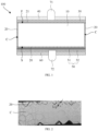
- FIG. 1 is a schematic structural diagram of a solar cell according to an embodiment of the present disclosure
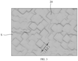
- FIG. 2 is a schematic structural diagram of a lateral surface of a substrate in the solar cell according to an embodiment of the present disclosure
- FIG. 3 is a schematic structural diagram of a second surface of the substrate in the solar cell according to an embodiment of the present disclosure.
- a solar cell 100 is provided.
- the solar cell 100 includes a substrate 10, a doped conductive layer 30, and a passivated contact layer 50.
- the substrate 10 includes a first surface F and a second surface S arranged opposite to each other and a plurality of lateral surfaces C adjacent to and located between the first surface F and the second surface S.
- a plurality of pyramid base shaped textured structures 20 are constructed on the second surface S and each of the lateral surfaces C.
- a minimum side length of each of top surfaces of the pyramid base shaped textured structures 20 arranged on the lateral surfaces C is L1
- a maximum side length of each of top surfaces of the pyramid base shaped textured structures 20 arranged on the second surface S is L2
- the doped conductive layer 30 is arranged on the first surface F.
- the passivated contact layer 50 includes a polysilicon doped conductive layer 52.
- the passivated contact layer 50 is arranged on the second surface S.
- the pyramid base shaped textured structures 20 are pyramid base shaped structures formed after the pyramid shaped textured structures 22 are polished, if a side length of a top surface of each of the pyramid base shaped textured structures 20 is longer, a protruding height of each of the pyramid base shaped textured structures 20 correspondingly formed is lower, and a degree of etching is higher. On the contrary, if the side length of the top surface of each of the pyramid base shaped textured structures 20 is shorter, the protruding height of each of the pyramid base shaped textured structures 20 correspondingly formed is higher, and the degree of etching is lower.
- the minimum side length L1 of each of the top surfaces of the pyramid base shaped textured structures 20 arranged on the lateral surfaces C and the maximum side length L2 of each of the top surfaces of the pyramid base shaped textured structures 20 arranged on the second surface S satisfy: L1 > L2, that is, making the side lengths of the top surfaces of the pyramid base shaped textured structures 20 arranged on the lateral surfaces C being all greater than the side lengths of the top surfaces of the pyramid base shaped textured structures 20 arranged on the second surface S, the heights of the pyramid base shaped textured structures 20 formed on the lateral surfaces C are lower than the heights of the pyramid base shaped textured structures 20 formed on the second surface S.
- the lateral surfaces C are etched to a higher degree.
- portions of the lateral surfaces C of the substrate 10 where doping elements diffuse into can be removed by etching as much as possible, which can prevent formation of leakage channels on the lateral surfaces C, thereby improving efficiency of the solar cell 100.
- each of the pyramid base shaped textured structures 20 is formed by etching a pyramid shaped textured structure, the each of the pyramid base shaped textured structures 20 may be in a shape of a truncated pyramid, such as a truncated triangular pyramid or a truncated quadrangular pyramid.
- the top surface of the pyramid base shaped textured structure 20 is a polygonal figure (including a case where the top of the pyramid base shaped textured structure 20 may be approximately regarded as a plane figure, and a case where the top of the pyramid base shaped textured structure 20 is a plane figure).
- the side length of the top surface of the pyramid base shaped textured structure 20 refers to a side length of the polygonal figure.
- the top surface of the pyramid base shaped textured structure 20 may be in a shape of a triangle, a quadrangle, or the like depending on the number of sides in the truncated pyramid.
- the minimum side length of the top surface of the pyramid base shaped textured structure 20 refers to the shortest side length in side lengths of the polygonal top surface of the pyramid base shaped textured structure 20.
- the maximum side length of the top surface of the pyramid base shaped textured structure 20 refers to the longest side length in the side lengths of the polygonal top surface of the pyramid base shaped textured structure 20.
- the top surface of the pyramid base shaped textured structure 20 is a regular polygon, all side lengths of the top surface are equal, thus the minimum side length of the top surface of the pyramid base shaped textured structure 20 refers to any side length of the polygonal top surface of the pyramid base shaped textured structure 20, and the maximum side length of the top surface of the pyramid base shaped textured structure 20 refers to any side length of the polygonal top surface of the pyramid base shaped textured structure 20.
- the substrate 10 is configured to receive incident light and generate photogenerated carriers.
- the solar cell 100 may be a TOPCon (Tunnel Oxide Passivated Contact) cell, and both the first surface F and the second surface S of the substrate 10 may be configured to receive incident light.
- TOPCon Tel Oxide Passivated Contact
- the solar cell 100 may include an N-type cell and a P-type cell.
- the substrate 10 of the N-type cell is doped with an N-type element
- the doped conductive layer 30 of the N-type cell is doped with a P-type element.
- the substrate 10 of the P-type cell is doped with a P-type element
- the doped conductive layer 30 of the P-type cell is doped with an N-type element.
- the doped conductive layer 30 is configured to form a PN junction with the substrate 10.
- the doped conductive layer 30 may be P-type doped, which may be, for example, a boron-doped doped conductive layer 30 (also called a P+ type emitter).
- the passivated contact layer 50 is arranged on the second surface S.
- the passivated contact layer 50 may be directly stacked on the second surface S of the substrate 10.
- the passivated contact layer 50 may reduce recombinations of carriers on a surface of the substrate 10, thereby increasing an open-circuit voltage of the solar cell 100 and improving photoelectric conversion efficiency of the solar cell 100.
- the passivated contact layer 50 may include a tunnel oxide layer 51 and a polysilicon doped conductive layer 52 sequentially stacked on the second surface S.
- the tunnel oxide layer 51 is configured to realize interface passivation on the second surface S of the substrate 10 to achieve a chemical passivation effect.
- the solar cell 100 may further include a first passivation film layer 40, a second passivation film layer 60, a first electrode 71, and a second electrode 72.
- the first passivation film layer 40 is stacked on the doped conductive layer 30.
- the first passivation film layer 40 plays surface passivation and antireflection roles in the solar cell 100, may perform better chemical passivation on dangling bonds on the surface of the substrate 10, and plays an antireflection role on the front surface of the solar cell 100.
- the first passivation film layer 40 includes a first passivation layer (not shown) and a first antireflection layer (not shown) that plays an antireflection role, which are sequentially stacked on the doped conductive layer 30.
- the second passivation film layer 60 is stacked on the passivated contact layer 50.
- the second passivation film layer 60 may also adopt a single-layer or multi-layer structure, and the second passivation film layer 60 may be made of silicon oxide, silicon nitride, or silicon oxynitride.
- the second passivation film layer 60 may play roles of passivation and antireflection at the same time.
- the first electrode 71 is arranged on the first passivation film layer 40, and the second electrode 72 is arranged on the second passivation film layer 60.
- the first electrode 71 is electrically connected to the doped conductive layer 30.
- the second electrode 72 penetrates through the second passivation film layer 60 and is electrically connected to the passivated contact layer 50.
- the minimum side length L1 of each of the top surfaces of the pyramid base shaped textured structures 20 arranged on the lateral surfaces C satisfies: L1 > 15 ⁇ m.
- any side length L3 of each of the top surfaces of the pyramid base shaped textured structures 20 arranged on the lateral surfaces C satisfies: 15 ⁇ m ⁇ L3 ⁇ 40 ⁇ m.
- portions of the lateral surfaces C where doping elements diffuse into can be removed by etching as much as possible, thereby minimizing a possibility of electric leakage.
- the maximum side length L2 of each of the top surfaces of the pyramid base shaped textured structures 20 arranged on the second surface S satisfies: L2 ⁇ 15 ⁇ m. If L2 is greater than 15 ⁇ m, the second surface S is etched to an excessively large degree, making the second surface S relatively flat, which may lead to large contact resistance between the second electrode 72 and the second surface S of the substrate 10 and result in a poor current collection effect of the solar cell 100.
- any side length L4 of each of the top surfaces of the pyramid base shaped textured structures 20 arranged on the second surface S satisfies: 7 ⁇ m ⁇ L4 ⁇ 10 ⁇ m.
- L4 is less than 7 ⁇ m
- the second surface S is etched to a relatively small degree, and the second surface S has poor flatness, which is not conducive to the passivated contact layer 50 to form close contact with the second surface S.
- the second surface S can be etched to a moderate degree, so that the passivated contact layer 50 can form good contact with the second surface S of the substrate 10, while the passivated contact layer 50 can have good adhesion, thereby reducing recombinations of photogenerated carriers on the back surface, prolonging a lifetime of minority carriers, and improving a passivation effect.
- contact resistance between a back electrode and the second surface S of the substrate 10 can also be reduced, so that the current collection effect of the solar cell 100 is better, and the efficiency of the solar cell 100 is also improved.
- a top end of the pyramid base shaped textured structures 20 is provided with depressions, and a depression depth D of each of the depressions satisfies: 50 nm ⁇ D ⁇ 1000 nm.
- the depression depth D can be within a reasonable range, so as to achieve a relative flat surface, reduce surface defect states, and improve passivation quality.
- a manufacturing method of a solar cell is provided.
- FIG. 4 is a schematic flowchart of a manufacturing method of a solar cell according to an embodiment of the present disclosure
- FIG. 5 is a schematic structural diagram of a base plate 101 in the manufacturing method of a solar cell according to an embodiment of the present disclosure
- FIG. 6 is a schematic diagram of forming pyramid base shaped textured structures 20 and a doped conductive layer 30 on a substrate 10 in the manufacturing method of a solar cell according to an embodiment of the present disclosure
- FIG. 7 is a schematic diagram of forming a passivated contact layer 50 and forming pyramid base shaped textured structures 20 on lateral surfaces C of the substrate 10 in the manufacturing method of a solar cell according to an embodiment of the present disclosure
- FIG. 8 is a schematic diagram of forming a first passivation film layer 40 and a second passivation film layer 60 in the manufacturing method of a solar cell according to an embodiment of the present disclosure.
- the manufacturing method of a solar cell provided in the embodiments of the present disclosure includes the following steps.
- a base plate 101 is provided, the base plate 101 includes a substrate 10, pyramid shaped textured structures 22 are constructed on surfaces of the substrate 10, element-doped conductive material layers 31 are stacked on the surfaces of the substrate 10, and the surfaces of the substrate 10 include a first surface F and a second surface S arranged opposite to each other and a plurality of lateral surfaces C adjacent to and located between the first surface F and the second surface S.
- the element-doped conductive material layers 31 on the second surface S and the lateral surfaces C are etched and removed, and the pyramid shaped textured structures 22 on the second surface S and the lateral surfaces C are etched into pyramid base shaped textured structures 20, to form a doped conductive layer 30 on the first surface F of the substrate 10.
- a passivated contact material layer is formed on the second surface S of the substrate 10, and the passivated contact material layer includes a polysilicon doped conductive material layer.
- the passivated contact material layer wraparound deposited on one side of the first surface F and the lateral surfaces C of the substrate 10 are etched and removed and the pyramid base shaped textured structures 20 on the lateral surfaces C are etched to form a passivated contact layer 50 on the second surface S, such that a minimum side length L1 of each of top surfaces of the pyramid base shaped textured structures 20 arranged on the lateral surfaces C and a maximum side length L2 of each of top surfaces of the pyramid base shaped textured structures 20 arranged on the second surface S satisfy: L1 > L2.
- the pyramid shaped textured structures 22 on the second surface S and the lateral surfaces C are etched into pyramid base shaped textured structures 20, and in the subsequent steps, the pyramid base shaped textured structures 20 on the lateral surfaces C are continuously etched, so that the minimum side length L1 of each of the top surfaces of the pyramid base shaped textured structures 20 arranged on the lateral surfaces C and the maximum side length L2 of each of the top surfaces of the pyramid base shaped textured structures 20 arranged on the second surface S satisfy: L1 > L2, and heights of the pyramid base shaped textured structures 20 formed on the lateral surfaces C are lower than heights of the pyramid base shaped textured structures 20 formed on the second surface S.
- the lateral surfaces C are etched to a higher degree.
- portions of the lateral surfaces C of the substrate 10 where doping elements diffuse into may be removed by etching as much as possible, which can prevent formation of leakage channels on the lateral surfaces C, thereby improving efficiency of the solar cell 100.
- the element-doped conductive material layers 31 each include an emitter material layer and a first oxide material layer (not shown) located on a side of the emitter material layer that facing away from the pyramid shaped textured structure 22.
- an emitter material layer may be formed on the first surface F of the substrate 10
- emitter material layers may be wraparound deposited on the second surface S and the lateral surfaces C
- a first oxide material layer such as borosilicate glass (BSG), also known as a silicon dioxide layer
- BSG borosilicate glass
- step S20 the step of etching and removing the element-doped conductive material layers 31 on the second surface S and the lateral surfaces C, and etching the pyramid shaped textured structures 22 on the second surface S and the lateral surfaces C into pyramid base shaped textured structures 20 includes:
- an HF solution with a concentration of 2% to 35% is used for etching in the etching step performed in the chain machine. It may be understood that during the etching, in order to prevent an influence on the emitter material layer on the first surface F, an immersion height of the etching solution of the chain machine should be lower than the first surface F of the substrate 10. Therefore, herein, the first oxide material layers on the second surface S and most regions on the lateral surfaces C close to the second surface S are actually removed.
- a temperature in the etching step performed in the trough machine ranges from 45°C to 90°C, and etching is performed through a first etching solution; wherein the first etching solution includes a NaOH or KOH solution with a concentration of 5% to 20% (further, the concentration is 8%) and an organic complex additive.
- the organic complex additive may specifically include a cationic surfactant, sodium glycolate, and sodium formate.
- the steps of etching and removing the emitter material layers and etching the pyramid shaped textured structures 22 into the pyramid base shaped textured structures 20 can be completed in a same etching process by controlling an etching speed and an etching direction, and the maximum side length L2 of each of the top surfaces of the pyramid base shaped textured structures 20 on the second surface S and the lateral surfaces C etched satisfies: L2 ⁇ 15 ⁇ m.
- the step of forming a passivated contact material layer on the second surface S of the substrate 10 includes: sequentially stacking and forming a tunnel material layer, a polysilicon doped material layer, and a second oxide material layer (which may be, for example, phosphosilicate glass (PSG)) on the second surface S of the substrate 10.
- a tunnel material layer for example, phosphosilicate glass (PSG)
- step S40 referring to FIG. 7 , the step of etching and removing the passivated contact material layer wraparound deposited on one side of the first surface F and the lateral surfaces C of the substrate 10 and etching the pyramid base shaped textured structures 20 on the lateral surfaces C includes:
- the etching is performed through a second etching solution, wherein the second etching solution includes a KOH or NaOH solution with a concentration of 5% to 30%, ethylenediaminetetraacetic acid disodium salt, polysaccharide, and sodium formate.
- the second etching solution includes a KOH or NaOH solution with a concentration of 5% to 30%, ethylenediaminetetraacetic acid disodium salt, polysaccharide, and sodium formate.
- steps of etching away the tunnel material layer and the polysilicon doping material layer and further etching the pyramid base shaped textured structures 20 on the lateral surfaces C can be completed in a same etching process by controlling an etching speed and an etching direction, and the maximum side length L1 of each of the top surfaces of the pyramid base shaped textured structures 20 on the lateral surfaces C etched satisfies: L1 > 15 ⁇ m.
- an HF solution with a concentration of 2% to 35% is used for etching in the etching step performed in the chain machine.
- the manufacturing method of a solar cell in the embodiments of the present disclosure is described below with a specific example.
- the method includes the following steps.
- step I referring to FIG. 5 , a substrate 10 is textured and boron-diffused, pyramid shaped textured structure 22 are formed on each surface of the substrate 10, and element-doped conductive material layers 31 are stacked and formed on each surface of the substrate 10, to form a base plate 101.
- step II referring to FIG. 6 , the first oxide material layers on the second surface S and the lateral surfaces C of the substrate 10 are etched and removed in a chain machine, and an HF solution with a concentration of 2% to 35% is used for etching in the etching step.
- the emitter material layers on the second surface S and the lateral surfaces C of the substrate 10 are etched and removed in a trough machine, and the pyramid shaped textured structures 22 on the second surface S and the lateral surfaces C are etched into the pyramid base shaped textured structures 20. Therefore, a textured layer 21 and the doped conductive layer 30 are formed, and any side length L4 of each of the top surfaces of the pyramid base shaped textured structures 20 arranged on the second surface S satisfies: 7 ⁇ m ⁇ L4 ⁇ 10 ⁇ m.
- a temperature of the etching ranges from 45°C to 90°C, and the etching is performed through a first etching solution.
- the first etching solution includes a NaOH or KOH solution with a concentration of 5% to 20% (further, the concentration is 8%) and an organic complex additive.
- step III referring to FIG. 7 , a tunnel material layer, a polysilicon doped material layer, and a second oxide material layer are sequentially stacked on the second surface S of the substrate 10.
- step IV the second oxide material layers on the first surface F and the lateral surfaces C of the substrate 10 are etched and removed in the chain machine, and an HF solution with a concentration of 2% to 35% is used for etching in the etching step.
- the tunnel material layer and the polysilicon doped material layer wraparound deposited on the first surface F and the lateral surfaces C of the substrate 10 are etched and removed in a trough machine, and the pyramid base shaped textured structures 20 on the lateral surfaces C are etched, to form the passivated contact layer 50, and any side length L3 of each of the top surfaces of the pyramid base shaped textured structures 20 arranged on the lateral surfaces C satisfies: 15 ⁇ m ⁇ L3 ⁇ 40 ⁇ m.
- the etching is performed through a second etching solution.
- the second etching solution includes a KOH or NaOH solution with a concentration of 5% to 30%, ethylenediaminetetraacetic acid disodium salt, polysaccharide, and sodium formate.
- etching and removing the BSG on one side of the first surface F and the PSG on one side of the second surface S of the substrate 10 may also be taken into account.
- step V referring to FIG. 1 and FIG. 8 together, a first passivation film layer 40 is formed on the doped conductive layer 30, and a second passivation film layer 60 is formed on the passivated contact layer 50.
- step VI referring to FIG. 1 , a first electrode 71 and a second electrode 72 are manufactured on the first passivation film layer 40 and the second passivation film layer 60 respectively.
- the solar cell 100 manufactured through step I to step VI above is tested for battery performance with the solar cell in the prior art.
- a reverse current IRev2 of the solar cell 100 in the embodiments of the present disclosure is reduced from 0.08 A to 0.04 A, and in a mass production line, a proportion of the reverse current IRev2 greater than 1 is reduced from 1.3% to 0.03%.
- the solar cell 100 manufactured with the method in this embodiment has higher efficiency.
- a solar cell 100 is provided. On the basis of the foregoing solar cell 100, sizes of the plurality of pyramid base shaped textured structures 20 arranged on the second surface S and the lateral surfaces C are improved. Other structures included in the solar cell 100 and the manufacturing method of a solar cell are similar to those in the foregoing embodiments. Details are not described herein again. Exemplarily, a perimeter of each of top surfaces of the pyramid base shaped textured structures 20 arranged on the lateral surfaces is C1, a perimeter of each of top surfaces of the pyramid base shaped textured structures 20 arranged on the second surface S is C2, and C1 > C2.
- the plurality of pyramid base shaped textured structures 20 are pyramid base shaped structures formed after the pyramid shaped textured structures 22 are polished, if the perimeter of the top surface of each of the pyramid base shaped textured structures 20 is longer, a protruding height of each of the pyramid base shaped textured structures 20 correspondingly formed is lower, and a degree of etching is higher. On the contrary, if the perimeter of the top surface of each of the pyramid base shaped textured structures 20 is shorter, the protruding height of each of the pyramid base shaped textured structures 20 correspondingly formed is higher, and the degree of etching is lower.
- portions of the lateral surfaces C of the substrate 10 where doping elements diffuse into can be removed by etching as much as possible, which can prevent formation of leakage channels on the lateral surfaces C, thereby improving efficiency of the solar cell 100.
- a photovoltaic module (not shown) is provided.
- the photovoltaic module includes at least one cell string.
- the cell string includes at least two solar cells 100 as described above.
- the solar cells 100 are connected together by series soldering.
- a photovoltaic system (not shown) is provided.
- the photovoltaic system includes the photovoltaic module described above.
- the photovoltaic system may be applied to photovoltaic power stations, such as ground power stations, rooftop power stations, and water surface power stations, or applied to devices or apparatuses that use solar energy to generate electricity, such as user solar power supplies, solar street lights, solar cars, and solar buildings.
- photovoltaic system may be applied to all fields required to use solar energy to generate electricity.
- the photovoltaic system may include a photovoltaic array, a combiner box, and an inverter.
- the photovoltaic array may be an array of a plurality of photovoltaic modules.
- the plurality of photovoltaic modules may form a plurality of photovoltaic arrays.
- the photovoltaic arrays are connected to the combiner box, and the combiner box may combine currents generated by the photovoltaic arrays.
- the combined current flows through the inverter and is converted into an alternating current suitable for a power grid, and then connected to the power grid to realize solar power supply.
Landscapes
- Photovoltaic Devices (AREA)
- Life Sciences & Earth Sciences (AREA)
- Engineering & Computer Science (AREA)
- Sustainable Development (AREA)
- Sustainable Energy (AREA)
Priority Applications (1)
| Application Number | Priority Date | Filing Date | Title |
|---|---|---|---|
| EP25194969.9A EP4622427A3 (de) | 2023-07-20 | 2024-05-28 | Solarzelle und herstellungsverfahren dafür, fotovoltaisches modul und fotovoltaisches system |
Applications Claiming Priority (1)
| Application Number | Priority Date | Filing Date | Title |
|---|---|---|---|
| CN202310892241.0A CN116613224B (zh) | 2023-07-20 | 2023-07-20 | 太阳能电池及其制作方法、光伏组件及光伏系统 |
Related Child Applications (2)
| Application Number | Title | Priority Date | Filing Date |
|---|---|---|---|
| EP25194969.9A Division EP4622427A3 (de) | 2023-07-20 | 2024-05-28 | Solarzelle und herstellungsverfahren dafür, fotovoltaisches modul und fotovoltaisches system |
| EP25194969.9A Division-Into EP4622427A3 (de) | 2023-07-20 | 2024-05-28 | Solarzelle und herstellungsverfahren dafür, fotovoltaisches modul und fotovoltaisches system |
Publications (4)
| Publication Number | Publication Date |
|---|---|
| EP4401150A2 true EP4401150A2 (de) | 2024-07-17 |
| EP4401150A3 EP4401150A3 (de) | 2025-01-22 |
| EP4401150C0 EP4401150C0 (de) | 2025-11-12 |
| EP4401150B1 EP4401150B1 (de) | 2025-11-12 |
Family
ID=87685771
Family Applications (2)
| Application Number | Title | Priority Date | Filing Date |
|---|---|---|---|
| EP25194969.9A Pending EP4622427A3 (de) | 2023-07-20 | 2024-05-28 | Solarzelle und herstellungsverfahren dafür, fotovoltaisches modul und fotovoltaisches system |
| EP24178573.2A Active EP4401150B1 (de) | 2023-07-20 | 2024-05-28 | Solarzelle, herstellungsverfahren dafür, fotovoltaisches modul und photovoltaiksystem |
Family Applications Before (1)
| Application Number | Title | Priority Date | Filing Date |
|---|---|---|---|
| EP25194969.9A Pending EP4622427A3 (de) | 2023-07-20 | 2024-05-28 | Solarzelle und herstellungsverfahren dafür, fotovoltaisches modul und fotovoltaisches system |
Country Status (5)
| Country | Link |
|---|---|
| US (2) | US12453209B2 (de) |
| EP (2) | EP4622427A3 (de) |
| CN (1) | CN116613224B (de) |
| AU (2) | AU2024204865B2 (de) |
| MX (1) | MX2024009002A (de) |
Cited By (2)
| Publication number | Priority date | Publication date | Assignee | Title |
|---|---|---|---|---|
| CN120456671A (zh) * | 2025-07-11 | 2025-08-08 | 鄂尔多斯市隆基光伏科技有限公司 | 一种太阳能电池和光伏组件 |
| JP7808231B1 (ja) * | 2024-09-27 | 2026-01-28 | 鄂爾多斯市隆基光伏科技有限公司 | 太陽電池及びソーラーモジュール |
Families Citing this family (5)
| Publication number | Priority date | Publication date | Assignee | Title |
|---|---|---|---|---|
| CN118016739B (zh) * | 2024-04-09 | 2025-03-11 | 浙江晶科能源有限公司 | 分片电池及其形成方法、光伏组件 |
| CN118335817A (zh) * | 2024-05-15 | 2024-07-12 | 西安隆基乐叶光伏科技有限公司 | 一种太阳能电池及其制造方法、光伏组件 |
| WO2025236816A1 (zh) * | 2024-05-15 | 2025-11-20 | 隆基绿能科技股份有限公司 | 太阳能电池及光伏组件 |
| CN118538798A (zh) * | 2024-06-14 | 2024-08-23 | 浙江爱旭太阳能科技有限公司 | 太阳能电池及光伏系统 |
| CN119584715B (zh) * | 2024-12-02 | 2025-09-02 | 隆基绿能科技股份有限公司 | 一种太阳能电池、光伏组件和半导体基片 |
Family Cites Families (25)
| Publication number | Priority date | Publication date | Assignee | Title |
|---|---|---|---|---|
| JP4557772B2 (ja) * | 2005-03-31 | 2010-10-06 | 三洋電機株式会社 | 光起電力装置 |
| JP2011258767A (ja) * | 2010-06-09 | 2011-12-22 | Sharp Corp | 太陽電池 |
| JP4980494B2 (ja) | 2010-06-25 | 2012-07-18 | 三菱電機株式会社 | 太陽電池セルおよびその製造方法 |
| DE102010035582B4 (de) * | 2010-08-27 | 2017-01-26 | Universität Konstanz | Verfahren zum Herstellen einer Solarzelle mit einer texturierten Frontseite sowie entsprechende Solarzelle |
| TWI431797B (zh) * | 2010-10-19 | 2014-03-21 | Ind Tech Res Inst | 選擇性射極之太陽能電池及其製作方法 |
| EP2562135A1 (de) * | 2011-08-22 | 2013-02-27 | ETH Zurich | Verfahren zur Herstellung und Ausrichtung von Nanowires und Anwendungen eines solchen Verfahrens |
| CN102856328B (zh) * | 2012-10-10 | 2015-06-10 | 友达光电股份有限公司 | 太阳能电池及其制作方法 |
| JPWO2014064769A1 (ja) | 2012-10-23 | 2016-09-05 | パナソニックIpマネジメント株式会社 | 太陽電池 |
| JP6311999B2 (ja) * | 2013-02-26 | 2018-04-18 | パナソニックIpマネジメント株式会社 | 太陽電池モジュールおよび太陽電池モジュールの製造方法 |
| JPWO2015068341A1 (ja) * | 2013-11-08 | 2017-03-09 | パナソニックIpマネジメント株式会社 | 太陽電池 |
| KR101740524B1 (ko) * | 2015-12-23 | 2017-06-08 | 엘지전자 주식회사 | 태양전지의 제조 방법과 이의 태양전지 |
| CN105826405A (zh) * | 2016-05-17 | 2016-08-03 | 常州天合光能有限公司 | 一种单晶硅双面太阳电池及其制备方法 |
| KR101919487B1 (ko) * | 2017-09-14 | 2018-11-19 | 한국과학기술연구원 | 반도체 기판을 텍스쳐링하는 방법과, 이 방법에 의해 제조된 반도체 기판, 그리고, 이러한 반도체 기판을 포함하는 태양 전지 |
| CN109638103A (zh) * | 2018-06-05 | 2019-04-16 | 中智(泰兴)电力科技有限公司 | 单晶硅异质结太阳电池用两面差异化绒面结构及制备方法 |
| CN110534595A (zh) * | 2019-09-06 | 2019-12-03 | 江西展宇新能源股份有限公司 | 一种perc双面太阳能电池及其制备方法 |
| JP2021057435A (ja) * | 2019-09-30 | 2021-04-08 | パナソニック株式会社 | 太陽電池セルおよび太陽電池セルの製造方法 |
| CN113224176B (zh) * | 2020-01-21 | 2022-10-04 | 隆基绿能科技股份有限公司 | 中间串联层、叠层光伏器件及生产方法 |
| CN111244208B (zh) | 2020-03-12 | 2022-02-18 | 常州时创能源股份有限公司 | 太阳能电池片及其应用 |
| JP7505123B2 (ja) | 2020-11-18 | 2024-06-24 | マープ インベンション エス.アール.オー. | 太陽光発電モジュールまたは太陽放射集光器の空間構造体 |
| GB202020727D0 (en) * | 2020-12-30 | 2021-02-10 | Rec Solar Pte Ltd | Solar cell |
| CN113594296B (zh) * | 2021-07-26 | 2025-03-11 | 西安隆基乐叶光伏科技有限公司 | 一种太阳能电池及其制造方法 |
| CN116741850A (zh) | 2022-06-08 | 2023-09-12 | 浙江晶科能源有限公司 | 一种太阳能电池及光伏组件 |
| CN115360262A (zh) | 2022-08-08 | 2022-11-18 | 江苏润阳世纪光伏科技有限公司 | 一种晶硅太阳能电池制绒工艺 |
| CN116995134A (zh) * | 2023-05-16 | 2023-11-03 | 天合光能股份有限公司 | 太阳能电池的制作方法 |
| CN116404071A (zh) * | 2023-06-07 | 2023-07-07 | 晶科能源(海宁)有限公司 | 一种太阳能电池及其制备方法、光伏组件 |
-
2023
- 2023-07-20 CN CN202310892241.0A patent/CN116613224B/zh active Active
-
2024
- 2024-05-28 EP EP25194969.9A patent/EP4622427A3/de active Pending
- 2024-05-28 EP EP24178573.2A patent/EP4401150B1/de active Active
- 2024-06-26 US US18/754,287 patent/US12453209B2/en active Active
- 2024-07-15 AU AU2024204865A patent/AU2024204865B2/en active Active
- 2024-07-19 MX MX2024009002A patent/MX2024009002A/es unknown
-
2025
- 2025-02-07 AU AU2025200841A patent/AU2025200841A1/en active Pending
- 2025-08-20 US US19/305,093 patent/US20250393339A1/en active Pending
Cited By (2)
| Publication number | Priority date | Publication date | Assignee | Title |
|---|---|---|---|---|
| JP7808231B1 (ja) * | 2024-09-27 | 2026-01-28 | 鄂爾多斯市隆基光伏科技有限公司 | 太陽電池及びソーラーモジュール |
| CN120456671A (zh) * | 2025-07-11 | 2025-08-08 | 鄂尔多斯市隆基光伏科技有限公司 | 一种太阳能电池和光伏组件 |
Also Published As
| Publication number | Publication date |
|---|---|
| US20240347653A1 (en) | 2024-10-17 |
| EP4401150A3 (de) | 2025-01-22 |
| CN116613224A (zh) | 2023-08-18 |
| AU2025200841A1 (en) | 2025-02-27 |
| AU2024204865A1 (en) | 2024-08-08 |
| EP4622427A3 (de) | 2025-12-17 |
| EP4401150C0 (de) | 2025-11-12 |
| EP4401150B1 (de) | 2025-11-12 |
| MX2024009002A (es) | 2025-02-10 |
| US20250393339A1 (en) | 2025-12-25 |
| EP4622427A2 (de) | 2025-09-24 |
| AU2024204865B2 (en) | 2025-01-02 |
| CN116613224B (zh) | 2023-09-29 |
| US12453209B2 (en) | 2025-10-21 |
Similar Documents
| Publication | Publication Date | Title |
|---|---|---|
| EP4401150B1 (de) | Solarzelle, herstellungsverfahren dafür, fotovoltaisches modul und photovoltaiksystem | |
| CN116314382B (zh) | 太阳能电池及其制作方法、光伏组件及光伏系统 | |
| US20250294913A1 (en) | Solar cell and photovoltaic module | |
| CN117637876B (zh) | 一种背接触电池及其制造方法 | |
| JP2025115934A (ja) | バックコンタクト電池及びその製造方法 | |
| CN117153953B (zh) | 开膜式双面TOPCon电池的制备方法 | |
| US20240363771A1 (en) | Solar cell, photovoltaic module, and photovoltaic system | |
| CN217881546U (zh) | 具有选择性发射极的钝化接触太阳电池及组件和系统 | |
| EP4629780A1 (de) | Solarzelle, verfahren zu ihrer herstellung und fotovoltaisches modul | |
| CN117393647A (zh) | 太阳能电池的制造方法、太阳能电池及光伏组件 | |
| CN119767836A (zh) | 背接触太阳能电池及其制作方法 | |
| CN119451313A (zh) | 背接触电池及其制作方法、光伏组件 | |
| CN119170665A (zh) | 太阳能电池及其制作方法、光伏组件 | |
| CN117727806A (zh) | 太阳能电池及其制备方法和光伏组件 | |
| US20250228036A1 (en) | Back-contact solar cell | |
| CN223402756U (zh) | 太阳能电池及太阳能电池组件 | |
| CN222941162U (zh) | 背接触电池及光伏组件 | |
| US20240395954A1 (en) | Solar cell and manufacturing method thereof, photovoltaic module and photovoltaic system | |
| CN119153549B (zh) | 隧穿氧化层钝化背接触太阳能电池及其制备方法、光伏组件、光伏系统 | |
| CN223568005U (zh) | 太阳能电池 | |
| CN120152438A (zh) | 太阳能电池及其制作方法及光伏组件 | |
| TWI535040B (zh) | 太陽能電池 | |
| CN118969875A (zh) | 背接触太阳能电池及其制备方法、光伏组件 | |
| CN119170699A (zh) | 太阳能电池及其制作方法 | |
| CN118507592A (zh) | 太阳能电池及其制作方法、光伏组件 |
Legal Events
| Date | Code | Title | Description |
|---|---|---|---|
| PUAI | Public reference made under article 153(3) epc to a published international application that has entered the european phase |
Free format text: ORIGINAL CODE: 0009012 |
|
| STAA | Information on the status of an ep patent application or granted ep patent |
Free format text: STATUS: REQUEST FOR EXAMINATION WAS MADE |
|
| 17P | Request for examination filed |
Effective date: 20240528 |
|
| AK | Designated contracting states |
Kind code of ref document: A2 Designated state(s): AL AT BE BG CH CY CZ DE DK EE ES FI FR GB GR HR HU IE IS IT LI LT LU LV MC ME MK MT NL NO PL PT RO RS SE SI SK SM TR |
|
| PUAL | Search report despatched |
Free format text: ORIGINAL CODE: 0009013 |
|
| AK | Designated contracting states |
Kind code of ref document: A3 Designated state(s): AL AT BE BG CH CY CZ DE DK EE ES FI FR GB GR HR HU IE IS IT LI LT LU LV MC ME MK MT NL NO PL PT RO RS SE SI SK SM TR |
|
| RIC1 | Information provided on ipc code assigned before grant |
Ipc: H01L 31/0216 20140101ALI20241216BHEP Ipc: H01L 31/0747 20120101ALI20241216BHEP Ipc: H01L 31/068 20120101ALI20241216BHEP Ipc: H01L 31/0236 20060101AFI20241216BHEP |
|
| REG | Reference to a national code |
Ref country code: DE Ref legal event code: R079 Free format text: PREVIOUS MAIN CLASS: H01L0031023600 Ipc: H10F0077700000 Ref country code: DE Ref legal event code: R079 Ref document number: 602024001239 Country of ref document: DE Free format text: PREVIOUS MAIN CLASS: H01L0031023600 Ipc: H10F0077700000 |
|
| GRAP | Despatch of communication of intention to grant a patent |
Free format text: ORIGINAL CODE: EPIDOSNIGR1 |
|
| STAA | Information on the status of an ep patent application or granted ep patent |
Free format text: STATUS: GRANT OF PATENT IS INTENDED |
|
| RIC1 | Information provided on ipc code assigned before grant |
Ipc: H10F 77/30 20250101ALI20250512BHEP Ipc: H10F 10/166 20250101ALI20250512BHEP Ipc: H10F 10/14 20250101ALI20250512BHEP Ipc: H10F 77/70 20250101AFI20250512BHEP |
|
| INTG | Intention to grant announced |
Effective date: 20250522 |
|
| GRAS | Grant fee paid |
Free format text: ORIGINAL CODE: EPIDOSNIGR3 |
|
| GRAA | (expected) grant |
Free format text: ORIGINAL CODE: 0009210 |
|
| STAA | Information on the status of an ep patent application or granted ep patent |
Free format text: STATUS: THE PATENT HAS BEEN GRANTED |
|
| AK | Designated contracting states |
Kind code of ref document: B1 Designated state(s): AL AT BE BG CH CY CZ DE DK EE ES FI FR GB GR HR HU IE IS IT LI LT LU LV MC ME MK MT NL NO PL PT RO RS SE SI SK SM TR |
|
| REG | Reference to a national code |
Ref country code: CH Ref legal event code: F10 Free format text: ST27 STATUS EVENT CODE: U-0-0-F10-F00 (AS PROVIDED BY THE NATIONAL OFFICE) Effective date: 20251112 Ref country code: GB Ref legal event code: FG4D |
|
| REG | Reference to a national code |
Ref country code: IE Ref legal event code: FG4D |
|
| REG | Reference to a national code |
Ref country code: DE Ref legal event code: R096 Ref document number: 602024001239 Country of ref document: DE |
|
| U01 | Request for unitary effect filed |
Effective date: 20251211 |
|
| U07 | Unitary effect registered |
Designated state(s): AT BE BG DE DK EE FI FR IT LT LU LV MT NL PT RO SE SI Effective date: 20251217 |