EP4399552B1 - Dispositif électroluminescent - Google Patents
Dispositif électroluminescent Download PDFInfo
- Publication number
- EP4399552B1 EP4399552B1 EP22769307.4A EP22769307A EP4399552B1 EP 4399552 B1 EP4399552 B1 EP 4399552B1 EP 22769307 A EP22769307 A EP 22769307A EP 4399552 B1 EP4399552 B1 EP 4399552B1
- Authority
- EP
- European Patent Office
- Prior art keywords
- solid
- light
- state light
- light source
- state
- Prior art date
- Legal status (The legal status is an assumption and is not a legal conclusion. Google has not performed a legal analysis and makes no representation as to the accuracy of the status listed.)
- Active
Links
Images


Classifications
-
- F—MECHANICAL ENGINEERING; LIGHTING; HEATING; WEAPONS; BLASTING
- F21—LIGHTING
- F21K—NON-ELECTRIC LIGHT SOURCES USING LUMINESCENCE; LIGHT SOURCES USING ELECTROCHEMILUMINESCENCE; LIGHT SOURCES USING CHARGES OF COMBUSTIBLE MATERIAL; LIGHT SOURCES USING SEMICONDUCTOR DEVICES AS LIGHT-GENERATING ELEMENTS; LIGHT SOURCES NOT OTHERWISE PROVIDED FOR
- F21K9/00—Light sources using semiconductor devices as light-generating elements, e.g. using light-emitting diodes [LED] or lasers
- F21K9/60—Optical arrangements integrated in the light source, e.g. for improving the colour rendering index or the light extraction
- F21K9/61—Optical arrangements integrated in the light source, e.g. for improving the colour rendering index or the light extraction using light guides
-
- F—MECHANICAL ENGINEERING; LIGHTING; HEATING; WEAPONS; BLASTING
- F21—LIGHTING
- F21K—NON-ELECTRIC LIGHT SOURCES USING LUMINESCENCE; LIGHT SOURCES USING ELECTROCHEMILUMINESCENCE; LIGHT SOURCES USING CHARGES OF COMBUSTIBLE MATERIAL; LIGHT SOURCES USING SEMICONDUCTOR DEVICES AS LIGHT-GENERATING ELEMENTS; LIGHT SOURCES NOT OTHERWISE PROVIDED FOR
- F21K9/00—Light sources using semiconductor devices as light-generating elements, e.g. using light-emitting diodes [LED] or lasers
- F21K9/20—Light sources comprising attachment means
- F21K9/23—Retrofit light sources for lighting devices with a single fitting for each light source, e.g. for substitution of incandescent lamps with bayonet or threaded fittings
- F21K9/232—Retrofit light sources for lighting devices with a single fitting for each light source, e.g. for substitution of incandescent lamps with bayonet or threaded fittings specially adapted for generating an essentially omnidirectional light distribution, e.g. with a glass bulb
-
- F—MECHANICAL ENGINEERING; LIGHTING; HEATING; WEAPONS; BLASTING
- F21—LIGHTING
- F21K—NON-ELECTRIC LIGHT SOURCES USING LUMINESCENCE; LIGHT SOURCES USING ELECTROCHEMILUMINESCENCE; LIGHT SOURCES USING CHARGES OF COMBUSTIBLE MATERIAL; LIGHT SOURCES USING SEMICONDUCTOR DEVICES AS LIGHT-GENERATING ELEMENTS; LIGHT SOURCES NOT OTHERWISE PROVIDED FOR
- F21K9/00—Light sources using semiconductor devices as light-generating elements, e.g. using light-emitting diodes [LED] or lasers
- F21K9/60—Optical arrangements integrated in the light source, e.g. for improving the colour rendering index or the light extraction
- F21K9/65—Optical arrangements integrated in the light source, e.g. for improving the colour rendering index or the light extraction specially adapted for changing the characteristics or the distribution of the light, e.g. by adjustment of parts
-
- G—PHYSICS
- G02—OPTICS
- G02B—OPTICAL ELEMENTS, SYSTEMS OR APPARATUS
- G02B6/00—Light guides; Structural details of arrangements comprising light guides and other optical elements, e.g. couplings
- G02B6/0001—Light guides; Structural details of arrangements comprising light guides and other optical elements, e.g. couplings specially adapted for lighting devices or systems
- G02B6/0011—Light guides; Structural details of arrangements comprising light guides and other optical elements, e.g. couplings specially adapted for lighting devices or systems the light guides being planar or of plate-like form
- G02B6/0033—Means for improving the coupling-out of light from the light guide
- G02B6/0035—Means for improving the coupling-out of light from the light guide provided on the surface of the light guide or in the bulk of it
- G02B6/0036—2-D arrangement of prisms, protrusions, indentations or roughened surfaces
-
- G—PHYSICS
- G02—OPTICS
- G02B—OPTICAL ELEMENTS, SYSTEMS OR APPARATUS
- G02B6/00—Light guides; Structural details of arrangements comprising light guides and other optical elements, e.g. couplings
- G02B6/0001—Light guides; Structural details of arrangements comprising light guides and other optical elements, e.g. couplings specially adapted for lighting devices or systems
- G02B6/0011—Light guides; Structural details of arrangements comprising light guides and other optical elements, e.g. couplings specially adapted for lighting devices or systems the light guides being planar or of plate-like form
- G02B6/0066—Light guides; Structural details of arrangements comprising light guides and other optical elements, e.g. couplings specially adapted for lighting devices or systems the light guides being planar or of plate-like form characterised by the light source being coupled to the light guide
- G02B6/0068—Arrangements of plural sources, e.g. multi-colour light sources
-
- G—PHYSICS
- G02—OPTICS
- G02B—OPTICAL ELEMENTS, SYSTEMS OR APPARATUS
- G02B6/00—Light guides; Structural details of arrangements comprising light guides and other optical elements, e.g. couplings
- G02B6/0001—Light guides; Structural details of arrangements comprising light guides and other optical elements, e.g. couplings specially adapted for lighting devices or systems
- G02B6/0011—Light guides; Structural details of arrangements comprising light guides and other optical elements, e.g. couplings specially adapted for lighting devices or systems the light guides being planar or of plate-like form
- G02B6/0066—Light guides; Structural details of arrangements comprising light guides and other optical elements, e.g. couplings specially adapted for lighting devices or systems the light guides being planar or of plate-like form characterised by the light source being coupled to the light guide
- G02B6/0073—Light emitting diode [LED]
-
- F—MECHANICAL ENGINEERING; LIGHTING; HEATING; WEAPONS; BLASTING
- F21—LIGHTING
- F21V—FUNCTIONAL FEATURES OR DETAILS OF LIGHTING DEVICES OR SYSTEMS THEREOF; STRUCTURAL COMBINATIONS OF LIGHTING DEVICES WITH OTHER ARTICLES, NOT OTHERWISE PROVIDED FOR
- F21V2200/00—Use of light guides, e.g. fibre optic devices, in lighting devices or systems
- F21V2200/20—Use of light guides, e.g. fibre optic devices, in lighting devices or systems of light guides of a generally planar shape
-
- F—MECHANICAL ENGINEERING; LIGHTING; HEATING; WEAPONS; BLASTING
- F21—LIGHTING
- F21Y—INDEXING SCHEME ASSOCIATED WITH SUBCLASSES F21K, F21L, F21S and F21V, RELATING TO THE FORM OR THE KIND OF THE LIGHT SOURCES OR OF THE COLOUR OF THE LIGHT EMITTED
- F21Y2105/00—Planar light sources
- F21Y2105/10—Planar light sources comprising a two-dimensional [2D] array of point-like light-generating elements
- F21Y2105/14—Planar light sources comprising a two-dimensional [2D] array of point-like light-generating elements characterised by the overall shape of the two-dimensional [2D] array
- F21Y2105/18—Planar light sources comprising a two-dimensional [2D] array of point-like light-generating elements characterised by the overall shape of the two-dimensional [2D] array annular; polygonal other than square or rectangular, e.g. for spotlights or for generating an axially symmetrical light beam
-
- F—MECHANICAL ENGINEERING; LIGHTING; HEATING; WEAPONS; BLASTING
- F21—LIGHTING
- F21Y—INDEXING SCHEME ASSOCIATED WITH SUBCLASSES F21K, F21L, F21S and F21V, RELATING TO THE FORM OR THE KIND OF THE LIGHT SOURCES OR OF THE COLOUR OF THE LIGHT EMITTED
- F21Y2107/00—Light sources with three-dimensionally disposed light-generating elements
- F21Y2107/90—Light sources with three-dimensionally disposed light-generating elements on two opposite sides of supports or substrates
-
- F—MECHANICAL ENGINEERING; LIGHTING; HEATING; WEAPONS; BLASTING
- F21—LIGHTING
- F21Y—INDEXING SCHEME ASSOCIATED WITH SUBCLASSES F21K, F21L, F21S and F21V, RELATING TO THE FORM OR THE KIND OF THE LIGHT SOURCES OR OF THE COLOUR OF THE LIGHT EMITTED
- F21Y2115/00—Light-generating elements of semiconductor light sources
- F21Y2115/10—Light-emitting diodes [LED]
Definitions
- US 2018/0283620 A1 discloses a lighting device which includes a filament, a filament fixing element, a driving circuit, a lamp holder and a bulb shell.
- the filament has a long strip bottom, installed with a plurality of LED modules.
- the filament fixing element has a bearing surface and a heat dissipation part. The bearing surface connects to the long strip bottom of the filament. The heat dissipation part is connected to the bearing surface to dissipate the heat.
- the driving circuit provides a suitable current to the filament for emitting light.
- the lamp holder houses the drive circuit and carries the filament fixing element.
- the bulb shell and the lamp holder constitute an accommodating space for receiving the filament and the filament fixing element.
- WO 2018/202625 discloses a light emitting device.
- Such a light emitting device is thereby provided with an improved appearance.
- a light emitting device in a lamp or a luminaire in turn provides for a lamp or a luminaire with a light output having an improved appearance.
- the one of the first side and the second side of the carrier being optically coupled to the light guide is further physically coupled to the light guide e.g. via an encapsulant.
- the light guide comprises a first major surface, a second major surface and at least one edge surface extending between the first major surface and the second major surface, and wherein the first solid-state light source filament is optically coupled to the at least one edge surface.
- the surface area of the first major surface and/or the second major surface may be at least 4 cm 2 , preferably at least 8 cm 2 , more preferably at least 10 cm 2 , most preferably at least 12 cm 2 .
- the first major surface and/or the second major surface of the light guide have a polygonal shape having at least 3 sides, preferably 4 sides.
- the first major surface and/or the second major surface of the light guide have a longest length, wherein the longest length of the first major surface and/or the second major surface of the light guide is larger than the length of the first and/or second solid-state light source filaments.
- the light guide is flat or non-flat e.g. curved.
- a light emitting device which ensures a more directionally focused light output.
- the first solid-state light source filament is further physically coupled to the at least one edge surface.
- the light guide comprises a shape selected from the group comprising flat, crown-shaped, twisted and helix-shaped.
- a light emitting device is provided for which may be adapted for a wide variety of uses and appearances.
- the light guide comprises light-outcoupling elements, where at least a part of the light which is coupled into the light guide is guided in the light guide, and where at least part of the light which is guided in the light guide is coupled out of the light guide via the light-outcoupling elements.
- a light emitting device with a further improved spectral light distribution and a further improved spatial light distribution is provided. Further, it is ensured that light is coupled out of the light guide at a desired location and in a desired direction.
- the light-outcoupling elements are arranged on a surface extending opposite to a surface to which the carrier is optically coupled.
- a light emitting device is provided with which it is ensured that light is coupled out of the light guide in such a location and manner that minimal interference with the solid-state light source filament is ensured.
- the light-outcoupling elements are chosen from the group comprising refractive elements, reflective elements, diffractive elements, scattering elements and combinations thereof.
- the first solid-state light source filament comprises a first encapsulant encapsulating the first plurality of solid-state light sources and a second encapsulant encapsulating the second plurality of solid-state light sources.
- the solid-state light source filaments may be protected from outside influences, such that a particularly robust and durable light emitting device is provided for.
- At least one of the first solid-state light source filament and the second solid-state light source filament is flexible.
- the carrier may be flexible.
- the encapsulant comprises a luminescent material adapted for converting at least a part of light emitted by one or more of the first plurality of solid-state light sources and the second plurality of solid-state light sources of the first solid-state light source filament and the plurality of solid-state light sources of the second solid-state light source filament.
- the first encapsulant comprises any one or more of a first light scattering material adapted for scattering the first solid-state light source light emitted by the first plurality of solid-state light sources of the first solid-state light source filament, and a first luminescent material adapted for converting at least a part of the first solid-state light source light emitted by the first plurality of solid-state light sources of the first solid-state light source filament
- the second encapsulant comprises any one or more of a second light scattering material adapted for scattering the second solid-state light source light emitted by the second plurality of solid-state light sources of the first solid-state light source filament, and a second luminescent material adapted for converting at least a part of the second solid-state light source light emitted by the second plurality of solid-state light sources of the first solid-state light source filament.
- the first encapsulant and the second encapsulant differ in terms of any one or more of (i) a concentration of luminescent material in the respective encapsulant, (ii) a type of luminescent material in the respective encapsulant, and (iii) a layer thickness of the respective encapsulant.
- the difference between the first output light and the second output light in terms of any one or more of different color points and different correlated color temperatures may be obtained by use and choice of the luminescent material.
- the first and second solid-state light sources may be identical solid-state light sources, such as e.g. solid-state light sources emitting blue light of the same wavelength.
- the first and second light exit surfaces of the solid-state light source filament corresponds to respective outer surfaces of a respective encapsulant.
- one of the first plurality of solid-state light sources and the second plurality of solid-state light sources is adapted for providing first light in a direction away from a first surface of the carrier and the other one of the first plurality of solid-state light sources and the second plurality of solid-state light sources is adapted for providing second light in a direction away from a second surface of the carrier opposite to the first surface of the carrier.
- one of the first plurality of solid-state light sources and the second plurality of solid-state light sources is adapted for providing first light in a direction away from the light guide and the other one of the first plurality of solid-state light sources and the second plurality of solid-state light sources is adapted for providing second light in a direction towards the light guide.
- a light emitting device is provided with which a light output with a more complex pattern may be obtained, and with which light output in two different directions may be obtained simultaneously.
- the first solid-state light source light emitted by the first solid-state light source filament is white light and the second solid-state light source light emitted by the second solid-state light source filament is colored light.
- the first solid-state light source light emitted by the first solid-state light source filament is white light comprising a first color temperature, CT1
- the second solid-state light source light emitted by the second solid-state light source filament is light comprising a second color temperature, CT2, being different from the first color temperature.
- the first color temperature is less than 2500 K, less than 2300 K, less than 2200 K, or even less than 2100 K, such as for example 2000 K.
- the second color temperature is at least 2700 K, at least 3000 K, at least 3300 K, or at least 3500 K, such as for example 4000 K.
- is at least 300 K, at least 500 K, at least 700 K, or at least 900 K, such as for example 1000 K.
- the luminaire or lamp may further comprise a controller for individually controlling at least the first plurality of solid-state light sources and the second plurality of solid-state light sources.
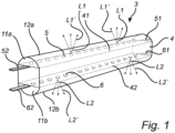
- the first plurality of solid-state light sources 5 are arranged on the first side 41 of the carrier 4.
- the second plurality of solid-state light sources 6 are arranged on the second side 42 of the carrier 4.
- the first solid-state light sources 5 of the light source filament 3 is adapted for providing first solid-state light source light L1 in a direction A away from a first surface 41 of the carrier 4 and the second solid-state light sources 6 of the light source filament 3 is adapted for providing second solid-state light source light L2 in a direction B away from a second surface 42 of the carrier 4 opposite to the first surface 41 of the carrier 4, or vice versa.
- the first solid-state light source light L1, or at least a majority thereof, provided by the first solid-state light sources 5 is coupled into the light guide 2, while the second solid-state light source light L2, or at least a majority thereof, provided by the second solid-state light sources 6 is not coupled into the light guide 2, or vice versa.
- the solid-state light source filament 3 further comprises a first light exit surface 12a and a second light exit surface 12b.
- the first light exit surface 12a and the second light exit surface 12b are surfaces of a first encapsulant 11a and a second encapsulant 11b, respectively, to be described in further detail below.
- the first light exit surface 12a and the second light exit surface 12b may be equivalent to surfaces of the first solid-state light sources 5 and the second solid-state light sources 6, respectively.
- the first solid state light source light L1 is emitted from the first light exit surface 12a of the solid-state light source filament 3 as first output light L1'
- the second solid-state light source light L2 is emitted from the second light exit surface 12b of the solid-state light source filament 3 as second output light L2'.
- the first plurality of solid-state light sources 5 is adapted for, in operation, emitting first solid-state light source light L1.
- the second plurality of solid-state light sources 6 are adapted for, in operation, emitting second solid-state light source light L2.
- the first solid-state light source light L1 comprises a first color point and a first color temperature.
- the second solid-state light source light L2 comprises a second color point and a second color temperature. At least one of, on the one hand the first color point and the second color point, and on the other hand the first color temperature and the second color temperature, are mutually different.
- the first plurality of solid-state light sources 5 and the second plurality of solid-state light sources 6 of the first solid-state light source filament 3 are chosen from the group comprising laser light sources, LEDs, UV LEDs, blue LEDs and white LEDs.
- the first plurality of solid-state light sources 5 further comprise connection elements 51, 52 adapted for connection to an energy source for providing electrical energy to the first plurality of solid-state light sources 5.
- the second plurality of solid-state light sources 6 further comprise connection elements 61, 62 adapted for connection to an energy source for providing electrical energy to the first plurality of solid-state light sources 6.
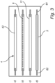
- Figs. 2 and 3 show top views of the opposite sides of a solid-state light source filament 3 of a light emitting device 1 according to the invention, featuring from the top down the different components thereof.
- Figs. 2 and 3 further illustrate a possible order of assembly of a solid-state light source filament 3 of a light emitting device according to the invention during manufacture.
- Fig. 2 shows a) the solid-state light source filament 3 seen form the first side 41 of the carrier 4, on which the electrical connection elements 51 and 52 are arranged, and b) on which the first plurality of solid-state light sources 5 are arranged.
- encapsulant 11 is provided, and the carrier 4 with connection elements 51, 52 and solid-state light sources 5 are d) encapsulated in the encapsulant 11.
- Fig. 3 shows a) the solid-state light source filament 3 seen form the second side 42 of the carrier 4, on which the electrical connection elements 61 and 62 are arranged, and b) on which the second plurality of solid-state light sources 6 are arranged.
- c) an encapsulant 11 is provided, and the carrier 4 with connection elements 61, 62 and solid-state light sources 6 are d) encapsulated in the encapsulant 11.
- the encapsulation with the encapsulant 11 may be performed separately for each side, or for both sides at the same time.
- the encapsulant 11 is generally an optically transparent material which is resistant to wear and deterioration caused by the light emitted by the solid-state light sources.
- the encapsulant 11 may comprise a light scattering material.
- the encapsulant may comprise a luminescent material adapted for converting at least a part of light emitted by the one or more solid-state light sources.
- the encapsulant 11 may enclose at least a part of the solid-state light sources 5 and 6, and the encapsulant 11 may furthermore encapsulate at least a part of the carrier 4.
- the encapsulant 11 encapsulating the first and second solid-state light sources 5 and 6 may be the same encapsulant.
- the first solid-state light source filament 3 may comprise a first encapsulant 11a encapsulating the first plurality of solid-state light sources 5 at least partially and a second encapsulant 11b encapsulating the second plurality of solid-state light sources 6 at least partially.
- the first encapsulant 11a may comprises any one or more of a first light scattering material adapted for scattering light emitted by the first plurality of solid-state light sources 5, and a first luminescent material adapted for converting at least a part of light emitted by the first plurality of solid-state light sources 5.
- the first plurality of solid-state light sources 5 and the second plurality of solid-state light sources 6 of the first solid-state light source filament 3 may both be, e.g., blue LEDs and the difference in color points or correlated color temperatures may be obtained by the light scattering material or the luminescent material converting the solid state light source light into converted solid state light source light.
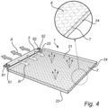
- Fig. 4 shows a perspective view of a light emitting device 1 according to a first embodiment of the invention.
- the light emitting device 1 generally comprises a light source filament 3 as described above and a light guide 2.
- the light guide 2 comprises a first major surface 21, a second major surface 22 and at least one edge surface 23.
- the edge surface 23 extends between the first major surface 21 and the second major surface 22 of the light guide 2.
- the carrier 4 of the light source filament 3 is optically coupled to the light guide 2 with one of the first side 41 and the second side 42.
- the one of the first side 41 and the second side 42 of the carrier 4 coupled optically to the light guide 2 may further be physically coupled to the light guide 2.
- first solid-state light source filament 3 is optically coupled to the at least one edge surface 23 of the light guide. Further, the first solid-state light source filament 3 may be physically coupled to the at least one edge surface 23 of the light guide 2.
- the first solid-state light sources 5 are arranged and adapted for providing first light in a direction A away from the light guide 2, and as shown more particularly the edge surface 23 of the light guide 2, and the second solid-state light sources 6 are adapted for providing second light in a direction B towards the light guide 2, and as shown more particularly the edge surface 23 of the light guide 2, or vice versa.
- the light guide 2 may further comprise light-outcoupling elements 7 arranged at an edge surface 24 of the light guide 2 opposite to the edge surface 23 to which the first solid-state light source filament 3 is coupled.
- the light guide 2 may also comprise light-outcoupling elements 8 arranged at a major surface, e.g. the major surface 21, of the light guide 2.
- Fig. 6 shows a perspective view of a light emitting device 101 according to a second embodiment of the invention.
- the light emitting device 101 differs from the light emitting devices 1 and 100 shown in Figs. 4 and 5 , respectively, and described above in that it comprises a further, second, solid-state light source filament 9.
Landscapes
- Physics & Mathematics (AREA)
- Engineering & Computer Science (AREA)
- Optics & Photonics (AREA)
- Microelectronics & Electronic Packaging (AREA)
- General Physics & Mathematics (AREA)
- General Engineering & Computer Science (AREA)
- Non-Portable Lighting Devices Or Systems Thereof (AREA)
Claims (15)
- Dispositif émetteur de lumière (1) comprenant un guide de lumière (2) et un premier filament source de lumière à semi-conducteurs (3) ;- le premier filament source de lumière à semi-conducteurs comprenant un support (4) comprenant un premier côté (41) et un second côté (42) opposé au premier côté, une première pluralité de sources de lumière à semi-conducteurs (5) étant agencée sur le premier côté du support, et une seconde pluralité de sources de lumière à semi-conducteurs (6) étant agencée sur le second côté du support ;- dans lequel la première pluralité de sources de lumière à semi-conducteurs sont conçues pour, en fonctionnement, émettre de la lumière de première source de lumière à semi-conducteurs (L1), la lumière de première source de lumière à semi-conducteurs étant émise par une première surface de sortie de lumière (12a) du premier filament source de lumière à semi-conducteurs en guise de première lumière de sortie (L1'), et la seconde pluralité de sources de lumière à semi-conducteurs étant conçue pour, en fonctionnement, émettre de la lumière de seconde source de lumière à semi-conducteurs (L2), la lumière de seconde source de lumière à semi-conducteurs étant émise par une seconde surface de sortie de lumière (12b) du premier filament source de lumière à semi-conducteurs en guise de seconde lumière de sortie (L2'), la première lumière de sortie (L1') étant différente de la seconde lumière de sortie (L2') en termes de l'un quelconque ou de plusieurs quelconques parmi des points de couleur et des températures de couleur corrélées ; et- dans lequel un seul parmi le premier côté (41) et le second côté (42) du support est couplé optiquement au guide de lumière (2).
- Dispositif émetteur de lumière selon la revendication 1, dans lequel celui du premier côté (41) et du second côté (42) du support étant couplé optiquement au guide de lumière est en outre accouplé physiquement au guide de lumière (2).
- Dispositif émetteur de lumière selon l'une quelconque des revendications précédentes, dans lequel le guide de lumière comprend une première surface principale (21), une seconde surface principale (22) et au moins une surface de bord (23) s'étendant entre la première surface principale et la seconde surface principale, et dans lequel le premier filament source de lumière à semi-conducteurs (3) est couplé optiquement à l'au moins une surface de bord (23).
- Dispositif émetteur de lumière selon la revendication 3, dans lequel le premier filament source de lumière à semi-conducteurs (3) est en outre accouplé physiquement à l'au moins une surface de bord (23).
- Dispositif émetteur de lumière selon l'une quelconque des revendications précédentes, dans lequel le guide de lumière (2) comprend une forme choisie dans le groupe comprenant plate, en forme de couronne, torsadée et en forme d'hélice.
- Dispositif émetteur de lumière selon l'une quelconque des revendications précédentes, dans lequel le guide de lumière (2) comprend des éléments de découplage de lumière (7 ; 8), dans lequel au moins une partie de la lumière qui est couplée dans le guide de lumière est guidée dans et à travers le guide de lumière, et dans lequel au moins une partie de la lumière qui est guidée dans et à travers le guide de lumière est découplée du guide de lumière par l'intermédiaire des éléments de découplage de lumière (7 ; 8).
- Dispositif émetteur de lumière selon la revendication 6, dans lequel les éléments de découplage de lumière (7 ; 8) sont un ou plusieurs parmiagencés sur une surface s'étendant opposée à une surface à laquelle le support est couplé optiquement, etchoisis dans le groupe comprenant des éléments réfractifs, des éléments réfléchissants, des éléments diffractifs, des éléments de diffusion et des combinaisons de ceux-ci.
- Dispositif émetteur de lumière selon l'une quelconque des revendications 3 à 7 précédentes, et comprenant un second filament source de lumière à semi-conducteurs (9), le second filament source de lumière à semi-conducteurs étant couplé optiquement à l'au moins une surface de bord (23) dans une position différente d'une position du premier filament source de lumière à semi-conducteurs (3).
- Dispositif émetteur de lumière selon la revendication 8, dans lequel le second filament source de lumière à semi-conducteurs (9) est en outre accouplé physiquement à l'au moins une surface de bord dans la position différente d'une position du premier filament source de lumière à semi-conducteurs.
- Dispositif émetteur de lumière selon la revendication 8 ou 9, dans lequel au moins l'un parmi le premier filament source de lumière à semi-conducteurs (3) et le second filament source de lumière à semi-conducteurs (9) est encapsulé par un agent d'encapsulation (11), ou selon l'une quelconque des revendications ci-dessus dans lequel
le premier filament source de lumière à semi-conducteurs (3) comprend un premier agent d'encapsulation (11a) encapsulant la première pluralité de sources de lumière à semi-conducteurs (5) et un second agent d'encapsulation (11b) encapsulant la seconde pluralité de sources de lumière à semi-conducteurs (6). - Dispositif émetteur de lumière selon la revendication 10, dans lequel l'agent d'encapsulation (11) comprend l'un quelconque ou plusieurs quelconques parmi :un matériau de diffusion de lumière conçu pour diffuser de la lumière émise par une ou plusieurs parmi la première pluralité de sources de lumière à semi-conducteurs (5) et la seconde pluralité de sources de lumière à semi-conducteurs (6) du premier filament source de lumière à semi-conducteurs (3) et une pluralité de sources de lumière à semi-conducteurs du second filament source de lumière à semi-conducteurs (9), etun matériau luminescent conçu pour convertir au moins une partie de la lumière émise par une ou plusieurs parmi la première pluralité de sources de lumière à semi-conducteurs (5) et la seconde pluralité de sources de lumière à semi-conducteurs (6) du premier filament source de lumière à semi-conducteurs (3) et la pluralité de sources de lumière à semi-conducteurs du second filament source de lumière à semi-conducteurs (9).
- Dispositif émetteur de lumière selon la revendication 10, dans lequel le premier agent d'encapsulation (11a) comprend l'un quelconque ou plusieurs quelconques parmi :un premier matériau de diffusion de lumière conçu pour diffuser la lumière de première source de lumière à semi-conducteurs (L1) émise par la première pluralité de sources de lumière à semi-conducteurs (5) du premier filament source de lumière à semi-conducteurs (3), etun premier matériau luminescent conçu pour convertir au moins une partie de la lumière de première source de lumière à semi-conducteurs (L1) émise par la première pluralité de sources de lumière à semi-conducteurs (5) du premier filament source de lumière à semi-conducteurs (3),et dans lequel le second agent d'encapsulation (11b) comprend l'une quelconque ou plusieurs quelconques parmi :un second matériau de diffusion de lumière conçu pour diffuser la lumière de seconde source de lumière à semi-conducteurs (L2) émise par la seconde pluralité de sources de lumière à semi-conducteurs (6) du premier filament source de lumière à semi-conducteurs (3), etun second matériau luminescent conçu pour convertir au moins une partie de la lumière de seconde source de lumière à semi-conducteurs (L2) émise par la seconde pluralité de sources de lumière à semi-conducteurs (6) du premier filament source de lumière à semi-conducteurs (3).
- Dispositif émetteur de lumière selon l'une quelconque des revendications précédentes, dans lequel l'une parmi la première pluralité de sources de lumière à semi-conducteurs (5) et la seconde pluralité de sources de lumière à semi-conducteurs (6) est conçue pour fournir de la première lumière dans une direction (A) à l'écart de la première surface (41) du support et l'autre parmi la première pluralité de sources de lumière à semi-conducteurs (5) et la seconde pluralité de sources de lumière à semi-conducteurs (6) est conçue pour fournir de la seconde lumière dans une direction (B) à l'écart de la seconde surface (42) du support opposée à la première surface du support.
- Dispositif émetteur de lumière selon l'une quelconque des revendications 8 à 13 précédentes, dans lequel la lumière de première source de lumière à semi-conducteurs émise par le premier filament source de lumière à semi-conducteurs (3) est de la lumière blanche et la lumière de seconde source de lumière à semi-conducteurs émise par le second filament source de lumière à semi-conducteurs (9) est de la lumière colorée, ou
dans lequel la lumière de première source de lumière à semi-conducteurs émise par le premier filament source de lumière à semi-conducteurs (3) est de la lumière blanche comprenant une première température de couleur et la lumière de seconde source de lumière à semi-conducteurs émise par le second filament source de lumière à semi-conducteurs (9) est de la lumière comprenant une seconde température de couleur différente de la première température de couleur. - Luminaire ou lampe (200) comprenant au moins un dispositif émetteur de lumière (1) selon l'une quelconque des revendications précédentes.
Applications Claiming Priority (2)
| Application Number | Priority Date | Filing Date | Title |
|---|---|---|---|
| EP21195005 | 2021-09-06 | ||
| PCT/EP2022/074277 WO2023031314A1 (fr) | 2021-09-06 | 2022-09-01 | Dispositif électroluminescent |
Publications (3)
| Publication Number | Publication Date |
|---|---|
| EP4399552A1 EP4399552A1 (fr) | 2024-07-17 |
| EP4399552C0 EP4399552C0 (fr) | 2025-04-16 |
| EP4399552B1 true EP4399552B1 (fr) | 2025-04-16 |
Family
ID=77640562
Family Applications (1)
| Application Number | Title | Priority Date | Filing Date |
|---|---|---|---|
| EP22769307.4A Active EP4399552B1 (fr) | 2021-09-06 | 2022-09-01 | Dispositif électroluminescent |
Country Status (6)
| Country | Link |
|---|---|
| US (1) | US12331893B2 (fr) |
| EP (1) | EP4399552B1 (fr) |
| CN (1) | CN117916638A (fr) |
| ES (1) | ES3031686T3 (fr) |
| PL (1) | PL4399552T3 (fr) |
| WO (1) | WO2023031314A1 (fr) |
Family Cites Families (13)
| Publication number | Priority date | Publication date | Assignee | Title |
|---|---|---|---|---|
| US9052416B2 (en) * | 2008-11-18 | 2015-06-09 | Cree, Inc. | Ultra-high efficacy semiconductor light emitting devices |
| US9028120B2 (en) * | 2011-08-08 | 2015-05-12 | Quarkstar Llc | Illumination devices including multiple light emitting elements |
| US9677738B2 (en) * | 2013-03-15 | 2017-06-13 | 1947796 Ontario Inc. | Optical device and system for solid-state lighting |
| CN106062479A (zh) * | 2014-02-24 | 2016-10-26 | 飞利浦照明控股有限公司 | 灯组件 |
| CN204254304U (zh) | 2014-09-24 | 2015-04-08 | 浙江承康机电制造有限公司 | 一种led灯 |
| CN207279318U (zh) | 2017-04-01 | 2018-04-27 | 漳州立达信光电子科技有限公司 | Led照明灯 |
| JP7080253B2 (ja) | 2017-05-02 | 2022-06-03 | シグニファイ ホールディング ビー ヴィ | 照明デバイス及び照明器具 |
| CN207424459U (zh) | 2017-10-23 | 2018-05-29 | 合肥惠科金扬科技有限公司 | 侧入式显示模组结构及显示器 |
| WO2020083647A1 (fr) | 2018-10-25 | 2020-04-30 | Signify Holding B.V. | Panneau de del utilisant des filaments de del pour fournir un éclairage efficace et homogène |
| US11519563B2 (en) | 2019-04-09 | 2022-12-06 | Signify Holding B.V. | Light-emitting device |
| CN114731748B (zh) * | 2019-11-15 | 2025-08-26 | 昕诺飞控股有限公司 | Led灯丝以及led灯丝灯 |
| CN212132369U (zh) * | 2020-04-26 | 2020-12-11 | 漳州立达信光电子科技有限公司 | 面环防水结构及防水灯具 |
| EP4189275B1 (fr) * | 2020-07-27 | 2024-09-11 | Signify Holding B.V. | Dispositif émetteur de lumière |
-
2022
- 2022-09-01 CN CN202280059920.3A patent/CN117916638A/zh active Pending
- 2022-09-01 PL PL22769307.4T patent/PL4399552T3/pl unknown
- 2022-09-01 ES ES22769307T patent/ES3031686T3/es active Active
- 2022-09-01 WO PCT/EP2022/074277 patent/WO2023031314A1/fr not_active Ceased
- 2022-09-01 US US18/689,203 patent/US12331893B2/en active Active
- 2022-09-01 EP EP22769307.4A patent/EP4399552B1/fr active Active
Also Published As
| Publication number | Publication date |
|---|---|
| ES3031686T3 (en) | 2025-07-10 |
| EP4399552C0 (fr) | 2025-04-16 |
| EP4399552A1 (fr) | 2024-07-17 |
| US20250129901A1 (en) | 2025-04-24 |
| WO2023031314A1 (fr) | 2023-03-09 |
| PL4399552T3 (pl) | 2025-07-07 |
| CN117916638A (zh) | 2024-04-19 |
| US12331893B2 (en) | 2025-06-17 |
Similar Documents
| Publication | Publication Date | Title |
|---|---|---|
| US10240724B2 (en) | LED filament | |
| US9275979B2 (en) | Enhanced color rendering index emitter through phosphor separation | |
| US12117132B2 (en) | Lighting emitting device | |
| CN114423988B (zh) | Led灯丝灯 | |
| US11739884B2 (en) | LED filaments with light-reflective particles for providing sparkle | |
| EP2542824B1 (fr) | Émetteur à indice de rendu des couleurs amélioré obtenu par séparation de luminophores | |
| US20140264420A1 (en) | Photoluminescence wavelength conversion components | |
| US10679975B2 (en) | Lighting device with UV LED | |
| WO2012090350A1 (fr) | Dispositif émetteur de lumière et lampe | |
| EP3987218B1 (fr) | Dispositif d'éclairage à température de couleur commandable comprenant différents filaments à del | |
| EP4038311B1 (fr) | Agencement de filament à del | |
| JP7461956B2 (ja) | Ledフィラメント構成 | |
| WO2020173895A1 (fr) | Dispositif d'éclairage | |
| EP4399552B1 (fr) | Dispositif électroluminescent | |
| JP2022524356A (ja) | Ledフィラメント構成 | |
| WO2025201945A1 (fr) | Filament de del | |
| WO2025252451A1 (fr) | Agencement de filament de del | |
| WO2026093176A1 (fr) | Agencement de filaments de del comprenant un ou plusieurs filaments de del | |
| WO2026017508A1 (fr) | Filament de del | |
| CN119137409A (zh) | Led灯丝 |
Legal Events
| Date | Code | Title | Description |
|---|---|---|---|
| STAA | Information on the status of an ep patent application or granted ep patent |
Free format text: STATUS: UNKNOWN |
|
| STAA | Information on the status of an ep patent application or granted ep patent |
Free format text: STATUS: THE INTERNATIONAL PUBLICATION HAS BEEN MADE |
|
| PUAI | Public reference made under article 153(3) epc to a published international application that has entered the european phase |
Free format text: ORIGINAL CODE: 0009012 |
|
| STAA | Information on the status of an ep patent application or granted ep patent |
Free format text: STATUS: REQUEST FOR EXAMINATION WAS MADE |
|
| 17P | Request for examination filed |
Effective date: 20240408 |
|
| AK | Designated contracting states |
Kind code of ref document: A1 Designated state(s): AL AT BE BG CH CY CZ DE DK EE ES FI FR GB GR HR HU IE IS IT LI LT LU LV MC MK MT NL NO PL PT RO RS SE SI SK SM TR |
|
| GRAP | Despatch of communication of intention to grant a patent |
Free format text: ORIGINAL CODE: EPIDOSNIGR1 |
|
| STAA | Information on the status of an ep patent application or granted ep patent |
Free format text: STATUS: GRANT OF PATENT IS INTENDED |
|
| DAV | Request for validation of the european patent (deleted) | ||
| DAX | Request for extension of the european patent (deleted) | ||
| INTG | Intention to grant announced |
Effective date: 20241112 |
|
| GRAS | Grant fee paid |
Free format text: ORIGINAL CODE: EPIDOSNIGR3 |
|
| GRAA | (expected) grant |
Free format text: ORIGINAL CODE: 0009210 |
|
| STAA | Information on the status of an ep patent application or granted ep patent |
Free format text: STATUS: THE PATENT HAS BEEN GRANTED |
|
| AK | Designated contracting states |
Kind code of ref document: B1 Designated state(s): AL AT BE BG CH CY CZ DE DK EE ES FI FR GB GR HR HU IE IS IT LI LT LU LV MC MK MT NL NO PL PT RO RS SE SI SK SM TR |
|
| REG | Reference to a national code |
Ref country code: GB Ref legal event code: FG4D |
|
| REG | Reference to a national code |
Ref country code: CH Ref legal event code: EP Ref country code: DE Ref legal event code: R096 Ref document number: 602022013313 Country of ref document: DE |
|
| REG | Reference to a national code |
Ref country code: IE Ref legal event code: FG4D |
|
| U01 | Request for unitary effect filed |
Effective date: 20250509 |
|
| U07 | Unitary effect registered |
Designated state(s): AT BE BG DE DK EE FI FR IT LT LU LV MT NL PT RO SE SI Effective date: 20250515 |
|
| REG | Reference to a national code |
Ref country code: ES Ref legal event code: FG2A Ref document number: 3031686 Country of ref document: ES Kind code of ref document: T3 Effective date: 20250710 |
|
| PG25 | Lapsed in a contracting state [announced via postgrant information from national office to epo] |
Ref country code: NO Free format text: LAPSE BECAUSE OF FAILURE TO SUBMIT A TRANSLATION OF THE DESCRIPTION OR TO PAY THE FEE WITHIN THE PRESCRIBED TIME-LIMIT Effective date: 20250716 Ref country code: GR Free format text: LAPSE BECAUSE OF FAILURE TO SUBMIT A TRANSLATION OF THE DESCRIPTION OR TO PAY THE FEE WITHIN THE PRESCRIBED TIME-LIMIT Effective date: 20250717 |
|
| PGFP | Annual fee paid to national office [announced via postgrant information from national office to epo] |
Ref country code: PL Payment date: 20250822 Year of fee payment: 4 |
|
| PG25 | Lapsed in a contracting state [announced via postgrant information from national office to epo] |
Ref country code: HR Free format text: LAPSE BECAUSE OF FAILURE TO SUBMIT A TRANSLATION OF THE DESCRIPTION OR TO PAY THE FEE WITHIN THE PRESCRIBED TIME-LIMIT Effective date: 20250416 |
|
| PG25 | Lapsed in a contracting state [announced via postgrant information from national office to epo] |
Ref country code: RS Free format text: LAPSE BECAUSE OF FAILURE TO SUBMIT A TRANSLATION OF THE DESCRIPTION OR TO PAY THE FEE WITHIN THE PRESCRIBED TIME-LIMIT Effective date: 20250716 |
|
| PG25 | Lapsed in a contracting state [announced via postgrant information from national office to epo] |
Ref country code: IS Free format text: LAPSE BECAUSE OF FAILURE TO SUBMIT A TRANSLATION OF THE DESCRIPTION OR TO PAY THE FEE WITHIN THE PRESCRIBED TIME-LIMIT Effective date: 20250816 |
|
| U20 | Renewal fee for the european patent with unitary effect paid |
Year of fee payment: 4 Effective date: 20250925 |
|
| PG25 | Lapsed in a contracting state [announced via postgrant information from national office to epo] |
Ref country code: SM Free format text: LAPSE BECAUSE OF FAILURE TO SUBMIT A TRANSLATION OF THE DESCRIPTION OR TO PAY THE FEE WITHIN THE PRESCRIBED TIME-LIMIT Effective date: 20250416 |
|
| PG25 | Lapsed in a contracting state [announced via postgrant information from national office to epo] |
Ref country code: CZ Free format text: LAPSE BECAUSE OF FAILURE TO SUBMIT A TRANSLATION OF THE DESCRIPTION OR TO PAY THE FEE WITHIN THE PRESCRIBED TIME-LIMIT Effective date: 20250416 |
|
| PG25 | Lapsed in a contracting state [announced via postgrant information from national office to epo] |
Ref country code: SK Free format text: LAPSE BECAUSE OF FAILURE TO SUBMIT A TRANSLATION OF THE DESCRIPTION OR TO PAY THE FEE WITHIN THE PRESCRIBED TIME-LIMIT Effective date: 20250416 |
|
| PGFP | Annual fee paid to national office [announced via postgrant information from national office to epo] |
Ref country code: ES Payment date: 20251015 Year of fee payment: 4 |
|
| PLBE | No opposition filed within time limit |
Free format text: ORIGINAL CODE: 0009261 |
|
| STAA | Information on the status of an ep patent application or granted ep patent |
Free format text: STATUS: NO OPPOSITION FILED WITHIN TIME LIMIT |
|
| REG | Reference to a national code |
Ref country code: CH Ref legal event code: L10 Free format text: ST27 STATUS EVENT CODE: U-0-0-L10-L00 (AS PROVIDED BY THE NATIONAL OFFICE) Effective date: 20260225 |
|
| 26N | No opposition filed |
Effective date: 20260119 |