EP4398495A2 - Kanalzugriffsverfahren für richtungssysteme in unlizenzierten bändern - Google Patents
Kanalzugriffsverfahren für richtungssysteme in unlizenzierten bändern Download PDFInfo
- Publication number
- EP4398495A2 EP4398495A2 EP24177702.8A EP24177702A EP4398495A2 EP 4398495 A2 EP4398495 A2 EP 4398495A2 EP 24177702 A EP24177702 A EP 24177702A EP 4398495 A2 EP4398495 A2 EP 4398495A2
- Authority
- EP
- European Patent Office
- Prior art keywords
- lbt
- transmission
- edcts
- node
- gnb
- Prior art date
- Legal status (The legal status is an assumption and is not a legal conclusion. Google has not performed a legal analysis and makes no representation as to the accuracy of the status listed.)
- Pending
Links
Images


Classifications
-
- H—ELECTRICITY
- H04—ELECTRIC COMMUNICATION TECHNIQUE
- H04W—WIRELESS COMMUNICATION NETWORKS
- H04W74/00—Wireless channel access
- H04W74/08—Non-scheduled access, e.g. ALOHA
- H04W74/0808—Non-scheduled access, e.g. ALOHA using carrier sensing, e.g. carrier sense multiple access [CSMA]
- H04W74/0816—Non-scheduled access, e.g. ALOHA using carrier sensing, e.g. carrier sense multiple access [CSMA] with collision avoidance
-
- H—ELECTRICITY
- H04—ELECTRIC COMMUNICATION TECHNIQUE
- H04B—TRANSMISSION
- H04B7/00—Radio transmission systems, i.e. using radiation field
- H04B7/02—Diversity systems; Multi-antenna system, i.e. transmission or reception using multiple antennas
- H04B7/04—Diversity systems; Multi-antenna system, i.e. transmission or reception using multiple antennas using two or more spaced independent antennas
- H04B7/06—Diversity systems; Multi-antenna system, i.e. transmission or reception using multiple antennas using two or more spaced independent antennas at the transmitting station
- H04B7/0686—Hybrid systems, i.e. switching and simultaneous transmission
- H04B7/0695—Hybrid systems, i.e. switching and simultaneous transmission using beam selection
- H04B7/06952—Selecting one or more beams from a plurality of beams, e.g. beam training, management or sweeping
- H04B7/0696—Determining beam pairs
Definitions
- the present disclosure is generally directed to methods and procedures related to channel access procedures for directional system in unlicensed bands. More particularly, the present disclosure relates to method performed by a receiving node to reserve a directional channel.
- Wireless communications may be deployed using licensed and/or unlicensed spectrums.
- An unlicensed spectrum may be used for non-cellular services and/or other applications (e.g., Wi-Fi).
- An unlicensed spectrum may be considered by cellular operators as a complementary tool.
- an unlicensed spectrum may augment a cellular operator's service offerings by meeting a high demand for broadband data.
- An unlicensed spectrum may pose additional constraints on the use of the spectrum since, for example, an unlicensed spectrum may be shared by users. Users may interfere with each other.
- Methods and systems are described herein for reserving a directional channel in the presence of potentially interfering nodes(s), such as in an unlicensed spectrum for instance.
- a method performed by a receiving node to reserve a directional channel includes: receiving a directional Request-to-Send (DRTS) message from a transmitting node; transmitting a directional Clear-to-Send (DCTS) message using one or more first beams, with at least one first beam being directed in a first direction towards the transmitting node; determining a second direction, the second direction being a different direction than the first direction; and transmitting at least one additional DCTS message using one or more second beams, with at least one second beam being directed in the second direction towards a potentially interfering node.
- the receiving node may be a wireless transmit/receive unit
- the transmitting node may be a base station.
- the method may be performed by the receiving node to reserve the directional channel in an unlicensed spectrum.
- the second direction may be determined based on information from a listen-before-talk (LBT) assessment of the directional channel.
- the message may contain an indication of the second direction, and the second direction may be determined based on the indication in the DRTS message.
- the second direction may be determined based on directional channel measurements.
- the at least one additional DCTS message includes multiple enhanced DCTS (eDCTS) messages.
- the at least one additional DCTS message may be transmitted multiple times within a maximum channel occupancy time (MCOT).
- the method further includes: receiving data from the transmitting node; and in between receiving the data from the transmitting node, periodically transmitting subsequent one or more additional DCTS messages in at least the second direction within a MCOT.
- transmitting the at least one additional DCTS message using the one or more second beams includes transmitting the at least one additional DCTS message on different beams.
- the method further includes: receiving a second DRTS message from the transmitting node; and transmitting a directional Deny-to-Send (DDTS) message to the transmitting node in response to the second DRTS message when the receiving node detects potential directional interference.
- the DDTS message may be an enhanced DDTS (eDDTS) message, and the eDDTS message may identify a node transmitting an interfering signal.
- the method further includes: performing a first directional listen-before-talk (LBT) assessment in a direction towards another node to which the receiving node intends to transmit, wherein the another node is different from the transmitting node; determining if a channel between the receiving node and the another node is busy based on the performed first directional LBT assessment; performing a second directional LBT assessment in a reverse direction; and determining if an interfering signal is detected from the reverse direction so as to either proceed with a transmission to the another node or defer the transmission if the interfering signal is detected.
- LBT listen-before-talk
- a wireless transmit/receive unit e.g., having a processor and a non-transitory computer-readable medium storing instructions for execution by the processor) to perform the methods described herein.
- a receiving node configured (e.g., having a processor and a non-transitory computer-readable medium storing instructions for execution by the processor) to perform the methods described herein.
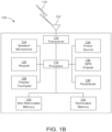
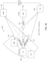
- FIG. 1A is a diagram illustrating an example communications system 100 in which one or more disclosed embodiments may be implemented.
- the communications system 100 may be a multiple access system that provides content, such as voice, data, video, messaging, broadcast, etc., to multiple wireless users.
- the communications system 100 may enable multiple wireless users to access such content through the sharing of system resources, including wireless bandwidth.
- the communications system 100 may include wireless transmit/receive units (WTRUs) 102a, 102b, 102c, 102d, a RAN 104/113, a CN 106/115, a public switched telephone network (PSTN) 108, the Internet 110, and other networks 112, though it will be appreciated that the disclosed embodiments contemplate any number of WTRUs, base stations, networks, and/or network elements.
- WTRUs 102a, 102b, 102c, 102d may be any type of device configured to operate and/or communicate in a wireless environment.
- the WTRUs 102a, 102b, 102c, 102d may be configured to transmit and/or receive wireless signals and may include a user equipment (UE), a mobile station, a fixed or mobile subscriber unit, a subscription-based unit, a pager, a cellular telephone, a personal digital assistant (PDA), a smartphone, a laptop, a netbook, a personal computer, a wireless sensor, a hotspot or Mi-Fi device, an Internet of Things (IoT) device, a watch or other wearable, a head-mounted display (HMD), a vehicle, a drone, a medical device and applications (e.g., remote surgery), an industrial device and applications (e.g., a robot and/or other wireless devices operating in an industrial and/or an automated processing chain contexts), a consumer electronics device, a device operating on commercial and/or industrial wireless networks, and the like.
- UE user equipment
- PDA personal digital assistant
- smartphone a laptop
- a netbook a personal computer
- the communications systems 100 may also include a base station 114a and/or a base station 114b.
- Each of the base stations 114a, 114b may be any type of device configured to wirelessly interface with at least one of the WTRUs 102a, 102b, 102c, 102d to facilitate access to one or more communication networks, such as the CN 106/115, the Internet 110, and/or the other networks 112.
- the base station 114a may be part of the RAN 104/113, which may also include other base stations and/or network elements (not shown), such as a base station controller (BSC), a radio network controller (RNC), relay nodes, etc.
- BSC base station controller
- RNC radio network controller
- the base station 114a and/or the base station 114b may be configured to transmit and/or receive wireless signals on one or more carrier frequencies, which may be referred to as a cell (not shown). These frequencies may be in licensed spectrum, unlicensed spectrum, or a combination of licensed and unlicensed spectrum.
- a cell may provide coverage for a wireless service to a specific geographical area that may be relatively fixed or that may change over time.
- the cell may further be divided into cell sectors. For example, the cell associated with the base station 114a may be divided into three sectors.
- the base station 114a may include three transceivers, i.e., one for each sector of the cell.
- the base station 114a may employ multiple-input multiple output (MIMO) technology and may utilize multiple transceivers for each sector of the cell.
- MIMO multiple-input multiple output
- beamforming may be used to transmit and/or receive signals in desired spatial directions.
- the base stations 114a, 114b may communicate with one or more of the WTRUs 102a, 102b, 102c, 102d over an air interface 116, which may be any suitable wireless communication link (e.g., radio frequency (RF), microwave, centimeter wave, micrometer wave, infrared (IR), ultraviolet (UV), visible light, etc.).
- the air interface 116 may be established using any suitable radio access technology (RAT).
- RAT radio access technology
- the communications system 100 may be a multiple access system and may employ one or more channel access schemes, such as CDMA, TDMA, FDMA, OFDMA, SC-FDMA, and the like.
- the base station 114a in the RAN 104/113 and the WTRUs 102a, 102b, 102c may implement a radio technology such as Universal Mobile Telecommunications System (UMTS) Terrestrial Radio Access (UTRA), which may establish the air interface 115/116/117 using wideband CDMA (WCDMA).
- WCDMA may include communication protocols such as High-Speed Packet Access (HSPA) and/or Evolved HSPA (HSPA+).
- HSPA may include High-Speed Downlink (DL) Packet Access (HSDPA) and/or High-Speed UL Packet Access (HSUPA).
- the base station 114a and the WTRUs 102a, 102b, 102c may implement a radio technology such as Evolved UMTS Terrestrial Radio Access (E-UTRA), which may establish the air interface 116 using Long Term Evolution (LTE) and/or LTE-Advanced (LTE-A) and/or LTE-Advanced Pro (LTE-A Pro).
- E-UTRA Evolved UMTS Terrestrial Radio Access
- LTE Long Term Evolution
- LTE-A LTE-Advanced
- LTE-A Pro LTE-Advanced Pro
- the base station 114a and the WTRUs 102a, 102b, 102c may implement a radio technology such as NR Radio Access, which may establish the air interface 116 using New Radio (NR).
- a radio technology such as NR Radio Access, which may establish the air interface 116 using New Radio (NR).
- the base station 114a and the WTRUs 102a, 102b, 102c may implement radio technologies such as IEEE 802.11 (i.e., Wireless Fidelity (WiFi), IEEE 802.16 (i.e., Worldwide Interoperability for Microwave Access (WiMAX)), CDMA2000, CDMA2000 1X, CDMA2000 EV-DO, Interim Standard 2000 (IS-2000), Interim Standard 95 (IS-95), Interim Standard 856 (IS-856), Global System for Mobile communications (GSM), Enhanced Data rates for GSM Evolution (EDGE), GSM EDGE (GERAN), and the like.
- IEEE 802.11 i.e., Wireless Fidelity (WiFi)
- IEEE 802.16 i.e., Worldwide Interoperability for Microwave Access (WiMAX)
- CDMA2000, CDMA2000 1X, CDMA2000 EV-DO Code Division Multiple Access 2000
- IS-95 Interim Standard 95
- IS-856 Interim Standard 856
- GSM Global System for
- the MME 162 may be connected to each of the eNode-Bs 162a, 162b, 162c in the RAN 104 via an S1 interface and may serve as a control node.
- the MME 162 may be responsible for authenticating users of the WTRUs 102a, 102b, 102c, bearer activation/deactivation, selecting a particular serving gateway during an initial attach of the WTRUs 102a, 102b, 102c, and the like.
- the MME 162 may provide a control plane function for switching between the RAN 104 and other RANs (not shown) that employ other radio technologies, such as GSM and/or WCDMA.
- the available frequency bands which may be used by 802.11ah, are from 902 MHz to 928 MHz. In Korea, the available frequency bands are from 917.5 MHz to 923.5 MHz. In Japan, the available frequency bands are from 916.5 MHz to 927.5 MHz. The total bandwidth available for 802.11ah is 6 MHz to 26 MHz depending on the country code.
- WTRUs 102a, 102b, 102c may communicate with gNBs 180a, 180b, 180c using signals in an unlicensed band.
- WTRUs 102a, 102b, 102c may communicate with/connect to gNBs 180a, 180b, 180c while also communicating with/connecting to another RAN such as eNode-Bs 160a, 160b, 160c.
- WTRUs 102a, 102b, 102c may implement DC principles to communicate with one or more gNBs 180a, 180b, 180c and one or more eNode-Bs 160a, 160b, 160c substantially simultaneously.
- eNode-Bs 160a, 160b, 160c may serve as a mobility anchor for WTRUs 102a, 102b, 102c and gNBs 180a, 180b, 180c may provide additional coverage and/or throughput for servicing WTRUs 102a, 102b, 102c.
- Listening and/or determining the usage of another may include and/or be based on measurements. Measurements may include energy detection.
- Frame based equipment may refer to equipment for which transmit/receive timing may be fixed and/or structured.
- Load based equipment (LBE) may not perform LBT/CCA according to a certain frame structure (e.g., at a fixed and/or defined time).
- LBE may perform LBT/CCA, for example, when it has data to transmit.
- Equipment may refer to a node and/or device that may transmit and/or receive on a licensed or unlicensed channel.
- equipment may include a UE, eNB, gNB, TRP, STA, and/or AP.
- Idle period may be the time (e.g., a consecutive period of time) during which the equipment may not transmit on the channel.
- the idle period may have a minimum requirement. The minimum requirement may be based on a COT. For example, the idle period may be 5% of the COT.
- the idle period may be used by the equipment, for example for the current fixed frame period.
- an operating channel(s) may transmit on the clear channel(s).
- the transmission may be immediate.
- the equipment may not transmit on the channel. For example, the equipment may not transmit on the channel until it performs a subsequent LBT/CCA, e.g., that finds the channel clear.
- the equipment may not transmit on that channel. For example, it may not transmit on the channel during the next fixed frame period.
- An LBT/CCA may be performed subsequent to a previous LBT/CCA.
- the previous LBT/CCA may have determined that a channel may not be clear.
- the subsequent LBT/CCA may involve a wait and/or backoff time before checking whether the channel may be clear.
- a UE may perform CCA to determine whether a channel may be free. If the UE determines the channel is not free, the UE may add an additional backoff and/or wait time (e.g., a contention window amount of time). If, for example, the UE determines the channel is free, the UE may check the channel again. This check may be before an actual transmission, for example, if the actual transmission may not begin right after the channel is determined to be free.
- an additional backoff and/or wait time e.g., a contention window amount of time.
- the UE may perform CCA for (e.g., at least) a check-window (e.g., a check window period of time) prior to an actual transmission.
- the UE may (e.g., only) transmit if, for example, the channel is determined to be free for a (e.g., at least a) part of the check-window.
- a CCA may be a full CCA or a short CCA.
- a full CCA may include adding a (e.g., one or more) backoff times. For example, a full CCA may be performed when a channel is determined to be busy.
- a short CCA may be a quick check (e.g., an energy detection check). For example, short CCA may be performed in a check-window prior to the start of transmission, and/or an intended and/or planned transmission.
- a UE may perform a full CCA, which may determine whether the channel is free.
- the UE may perform a short CCA prior to an actual transmission.
- the short CCA may be performed, for example, to re-check that the channel is still free. This may occur if there is a gap between the end of the full CCA and the start of the transmission.
- Access, use of resources, and/or transmission of resources on a channel, in cell, to a cell, to a TRP and/or another node may be grant-based, allocation-based, and/or scheduler-based.
- a grant and/or allocation may be provided (e.g., explicitly). For example, an allocation may be provided in a DL control information (DCI).
- DCI DL control information
- a grant and/or allocation may be configured, for example, by higher layer signaling.
- a grant and/or allocation may be used by the UE when the UE has data to transmit.
- Access, use of resources, and/or transmission on resources on a channel, in cell, to a cell, to a TRP and/or another node may be grant-less and/or grant-free. Grant-less and grant-free may be used interchangeably herein. Resources may be time and/or frequency resources.
- a UE may transmit on a (e.g., a set) of resources when the UE has a transmission to make.
- the UE may determine and/or select the resources on which to transmit from one or more resource(s).
- the resource(s) may be, for example, a configured set of resources.
- Resource(s) may be shared and/or used by another UE.
- the resource(s) may be referred to as contention-based resources.
- the transmissions of a (e.g., multiple) UEs may collide when the UEs choose and/or transmit on the same resources at the same time.
- Resource selection may be determined randomly (e.g., partially randomly). Resource selection may be a function of a UE-ID. Different UE(s) (e.g., groups of UE(s)) may be configured with different resources (e.g., sets of resources).
- direcocedures may be designed for omni-directional based systems.
- transmission energy may be propagated (e.g., equally) in (e.g., all) directions. This may be sensed, for example, by devices (e.g. all devices) residing within the channel sense range of the receivers.
- the signal energy for a transmission may concentrate in a spatial region (e.g., a narrow spatial region) covered by the transmitted beam.
- Devices located in the region of the transmitted beam may sense the presence of the transmissions.
- Devices located outside of the region of the transmitted beam may not be able to sense the transmission.
- a device may sense the channel as clear to send. The device may start transmission, which may interfere and/or collide with an ongoing transmission.
- an eDCTS-to-Self message may be configured differently from the eDCTS message. For example, a successful eDRTS and eDCTS transmission may be followed by multiple eDCTS-to-Self transmissions. The multiple eDCTS-to-Self transmissions may be sent on multiple beams. Dynamic downlink/uplink (DL/UL) switching configurations may be used, which may cause other device transmissions not to interfere with an ongoing transmission.
- DL/UL Dynamic downlink/uplink
- implementations for directional new radio (NR)-WiGig system coexistence in unlicensed bands may be performed.
- DL/UL switching configurations for a NR link may be determined based on a minimum distributed inter frame spacing (DIFS) duration in the WiGig system.
- Transmissions may be configured to be performed in a reverse direction per each window (e.g., DIFS period). Multiple block transmissions in the reverse direction may be sent. The transmit power of the transmissions may be increased.
- a listen-before-talk may be performed in paired directions (e.g., in the direction of a receiver and in an opposite direction). This may reduce a number of hidden nodes that may interfere with an ongoing transmission.
- LBT parameters e.g., beamwidth, energy detection (ED) thresholds
- ED energy detection
- a transmit and receive strategy may be determined based on a function of the sensed power/energy during the LBT.
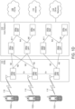
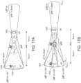
- one NR system may include, e.g., a UE 208 (also denoted as “UE 1”) and/or gNB 210 (also denoted as “gNB 1"), and another NR system may include, e.g., a UE 212 (also denoted as “UE 2”) and/or a gNB 214 (also denoted as "gNB 2").
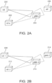
- the STA 308 is placed between the gNB 304 as the transmitting node and the UE receiver, and/or the STA 308 is not sensed by legacy LBT (see, e.g., FIG. 3B ), interference may be received at the STA 308.
- interference problems due to directional hidden nodes may arise when a transmitting node is, e.g., a UE and a receiving node is, e.g., a gNB.
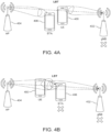
- FIG. 4A illustrates an example of a carrier sense in a LBT with interference from an AP received at a gNB.
- FIG. 4B illustrates an example of a carrier sense in a LBT with interference from a UE received at a STA and/or from an AP at a gNB.
- implementations associated with coexistence of directional NR-NR systems in unlicensed bands may be provided.
- the transmission may be configured so that other transmission(s) from other device(s), which may interfere with the transmission between the transmitting node and the receiving node may not be started.
- the configuration of such DL/UL switching may be done through eDRTS and/or eDCTS message(s).
- the transmitting node may not start its transmission if, for example, it does not receive the eDCTS from the receiving node (e.g., within a configurable amount of time). For example, upon transmitting the eDRTS, the transmitting node may start a timer. If, for example, it does not receive the eDCTS before expiration of the timer, the transmitting node may consider the CCA procedure unsuccessful.
- a NR New Radio
- a NR utilizes a beam management procedure through which UE may dynamically report to a gNB, e.g., the best transmit (Tx) beam/beam ID (e.g., from the perspective of the UE) for transmitting to that UE.
- the gNB may then use that Tx beam to transmit any data intended for the UE.
- An eDRTS message on a Tx beam corresponding to a Rx beam (e.g., from the perspective of a transmitting node), on which the transmitting node may perform a successful CCA, may comprise one or more of the example information indications in Table 1, in accordance with some embodiments.
- the "Transmitter Identification” and "Receiver Identification” fields may be used by other nodes to infer a direction of upcoming transmission(s) indirectly (e.g., the ID fields may map to such direction indirectly).
- the Receiver identification may be used by other node(s) to determine whether they are intended recipient(s) of a given transmission.
- DL/UL switching configuration This configuration may be used after the successful channel reservation process (e.g., after the successful reception of eDCTS at the UE/gNB transmitter). This information may be included when the UE/gNB transmitter has the knowledge (e.g., complete knowledge) of the resource allocation for this transmission. For example, if a UE sends eDRTS when it does not have granted resources, it may not include the DL/UL switching configuration.
- the DL/UL switching configuration may also indicate a slot size to use for an upcoming transmission occasion.
- the information provided are examples of what an enhanced message may include in accordance with some embodiments.
- the eDCTS message may be configured, for example, with a subset (e.g., different subset) of the example information in Table 2, in accordance with some embodiments. For example, if a UE sends eDCTS after receiving the eDRTS from the gNB with DL/UL switching configuration and/or signal type, the UE may include the remaining duration of the complete transmission, transmitter identification, and/or receiver identification in the eDCTS.
- This may include UE's C-RNTI, gNB's cell ID, and/or the like. This information may be available to the UE/gNB if, for example, it successfully decodes an eDRTS/eDCTS exchange between interfering entities.
- interfering Receiver Identifier Identifies the receiver of the interfering signal. This may include UE's C-RNTI, gNB's cell ID, and/or the like. This information may be available to the UE/gNB if it successfully decodes an eDRTS/eDCTS exchange between interfering entities.
- Defer Duration Specifies the amount of time for which the transmission may be deferred.
- the eDDTS message may be configured with a subset (e.g., a different subset) of the example information in Table 3, in some embodiments.
- the eDDTS may include a (e.g., just a) transmitter identifier and/or receiver identifier field(s).
- the eDDTS may comprise (e.g., all) the fields listed in Table 3.
- a transmitting node e.g., a gNB or a receiving node (e.g., UE) may transmit an enhanced Directional Clear-to-Send (eDCTS) to self, or an enhanced Directional Clear-to-Send-to-Self (eDCTS-to-Self), for example, to reserve a directional channel for a (e.g., planned) directional transmission(s) with (e.g., one or more) respective receiving node(s) (e.g., UE(s)) or transmitting node(s) (e.g., gNB(s)).
- An eDCTS-to-Self transmission may and/or may not be preceded by an eDRTS transmission or reception.
- the eDCTS-to-Self message may be an eDCTS message sent by, e.g., a receiving node to itself.
- an eDCTS-to-Self message may be configured differently than an eDCTS message, e.g., with one or more different fields, formats, or information.
- the number of eDCTS-to-Self transmissions, and the directions for the eDCTS-to-Self transmissions may be known to a UE or a gNB through measurements.
- the UE or gNB may determine an absence or a presence of interfering links via measurements and eDCTS-to-Self transmissions may occur only in directions or antenna configurations or beams that are known to be interfere-prone.
- the DCI may be configured differently (e.g., the DCI may contain one or more different fields, additional field(s), and/or less fields than disclosed herein).
- the eDCTS message may also contain a subset of the following information, as shown by way of example in Table 7, in accordance with some embodiments.
- Start Time Indicates a start time of DL data transmission. This field may be present when a transmission duration field, i.e., Remaining duration of the complete transmission indicates a duration for DL data transmission only.
- Remaining eDCTS count Indicates a number of remaining eDCTS transmissions in a current sequence. This field may be present when a transmission Duration field indicates a duration for DL data transmission only.
- Tx Beam ID This field identifies an antenna configuration, e.g., a beam intended for use during subsequent DL data transmission by a requesting node, e.g., eNB/gNB.
- a Receiver ID may be the same as UE's C-RNTI.
- the Receiver ID may be a different ID that is configured using e.g., control channel signal(s), higher layer signaling, etc.
- a UE may transmit an eDRTS message to request an uplink transmission, or a eDCTS message in response to a eDRTS message received from a BS (base station) associated with the UE, or eDCTS-to-Self transmissions which may be transmitted in various ways as described hereinabove.
- the UE may receive control channel transmission in a common channel (e.g. PDCCH).
- the received control information may include a DCI containing a grant for an uplink transmission in a shared channel, e.g. a Physical Uplink Shared Channel (PUSCH).
- PUSCH Physical Uplink Shared Channel
- the UE may transmit an eDRTS/eDCTS to the associated BS first in a sequence of multiple eDRTS/eDCTS transmissions. In other embodiments, the UE may transmit an eDRTS/eDCTS to the associated BS last in a sequence of multiple eDRTS/eDCTS transmissions. In one embodiment, the UE may not include a field to indicate a total number of eDRTS/eDCTS transmissions in a current sequence. In yet another embodiment, the UE may transmit an eDRTS/eDCTS to the associated BS in a random location in the current sequence of multiple eDRTS/eDCTS transmissions.
- the UE may be configured to transmit multiple eDRTS/eDCTS messages. Successive eDRTS/eDCTS transmissions may use different antenna configurations, e.g., different beams.
- the UE may change the contents of the eDRTS/eDCTS message transmitted using different antenna configurations, e.g., different beams.
- the UE may decrement a transmission duration field in each successive transmission of the eDRTS/eDCTS message by an amount required for a single eDRTS/eDCTS message transmission.
- eDRTS, eDCTS, and eDCTS-to-Self transmission may occur using an uplink common channel.
- a UE may not receive any specific UL resource grant in advance from an associated BS associated with the UE, e.g., an eNB/gNB, for the purpose of eDRTS/eDCTS/eDCTS-to-Self transmission. If the UE determines that no resource(s) were granted for the eDRTS/eDCTS/eDCTS-to-Self transmission, then, in some embodiments, the UE may transmit an eDCTS message using UL Grant-less resource(s).
- the UL Grant-less Channel may be, by way of example, designed in one or more of the following ways, as described, e.g., below.
- the UL Grant-less Channel may be located in one or more subframes in each frame or certain frame(s), e.g., frame(s) with certain SFN number(s) or frame(s) with SFN(s) with certain properties.
- the subframes and/or frames and/or frame properties may be fixed or may be a function of a cell's physical ID (cell ID).
- the UE may be previously configured with a location of the UL Grant-less Channel, e.g., via System Information, a downlink Broadcast Information, or UE-specific signaling.
- a sequence and/or identifier to be used for scrambling of the UL Grant-less Channel may be common to a group of cells, e.g., CGS.
- a common CGS may be used for the entire operator network.
- a single CGS may be frequency channel or sub-band specific (e.g., all devices operating in a frequency channel or sub-band support the same CGS.
- a UE may be configured with multiple CGSs.
- the gNBs and/or UEs may be configured to listen and decode the UL Grant-less Channel.
- DM-RS Demodulation Reference Signal
- the sequence to derive the DM-RS may be based on a common sequence, e.g., a CGS. In one embodiment, the sequence to derive DM-RS may be based on a UE-specific sequence.
- the position of the DM-RS in the dedicated resources may be fixed, known or configured.
- the eDRTS on the dedicated resources may be scrambled using UE-specific scrambling sequence.
- the UE may be previously configured with dedicated resource allocation, and further configured with a UE-specific scrambling sequence, e.g., via higher layer signaling message, e.g., a RRC Connection Setup or via System Information.
- a UE-specific scrambling sequence e.g., via higher layer signaling message, e.g., a RRC Connection Setup or via System Information.
- a non-targeted UE or a neighboring BS that receives an eDRTS or/and eDCTS or/and eDCTS-to-Self transmission that includes another Cell'd ID or another UE's ID may not transmit on a channel for transmission duration indicated in the message.
- the transmission duration may be specified for the entire message exchange including remaining eDRTS, eDCTS, eDCTS-to-Self transmissions and subsequent data transmission. Alternately, the transmission duration may be specified in terms of start time and a duration.
- a UE belonging to a neighboring cell or a neighboring BS that receives an eDRTS or/and an eDCTS or/and an eDCTS-to-Self transmissions that includes another Cell's ID or UE's ID may transmit on a frequency channel or sub-band if it determines that doing so will not cause interference to subsequent transmission associated with the received eDRTS/eDCTS/eDCTS-to-Self message.
- a non-targeted UE belonging to a neighboring cell or a neighboring BS may determine whether its directional transmission (e.g., UL or DL transmission) may not interfere with the directional transmission between the BS and targeted UE, following exchange of eDRTS, eDCTS, and eDCTS-to-Self (if any), then that UE or neighboring BS may perform concurrent (e.g., simultaneous) directional transmissions.
- eDRTS e.g., UL or DL transmission
- the UE or the BS may first determine if the channel may be free for transmission for a specified duration prior to any subsequent transmissions.
- the monitoring duration may be previously configured or may be known to the UE or BS.
- the UE may perform a CCA (e.g., a LBT) for the monitoring duration.
- the determination (e.g., the CCA) may be performed before the time when the transmission may start.
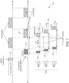
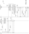
- a transmitting node such as a gNB in FIG. 33 , may first perform a CCA to determine if the channel is clear/free for transmission. Once the gNB determines that the channel is clear, at 2702, it may transmit a new DCI on a downlink common channel, such as a PDCCH, to a receiving node, which in FIG. 33 , is a targeted UE.
- the DCI may be scrambled using a common RNTI.
- the common RNTI may be common to more than one UE or common throughout a network, such as, e.g., a SI-RNTI.
- the targeted UE may decode the eDRTS and determine that the UE ID included in the eDRTS corresponds to an ID of the targeted UE.
- the non-targeted UE and/or the neighboring gNB may decode the eDRTS and determine that the UE ID included in the eDRTS does not match an ID of the targeted UE.
- the non-targeted UE and/or the neighboring gNB may obtain from the decoded eDRTS the transmission duration (or at least an indication thereof).
- the non-targeted UE and/or the neighboring gNB may not initiate transmission(s) for the Tx duration obtained from the received eDRTS.
- the non-targeted UE and/or the neighboring gNB may be prevented from interfering with the transmissions between the gNB and the targeted UE during at least that time period.
- the DL data transmission may be followed by one or more eDCTS-to-Self transmissions during a period T (denoted by 2724 in FIG. 33 ) that may, for example, correspond to a minimum LBT duration.
- the gNB may perform multiple repeated eDCTS-to-Self transmissions 2722 in multiple directions, if so configured, during the period 2724.
- the eDCTS-to-Self transmission(s) may be performed to keep the (directional) channel between the gNB and the targeted UE reserved from access by potentially interfering node(s).
- the gNB If the gNB has additional data to send, at 2726, it transmits the additional DL data to the targeted UE.
- the DL data transmission may be again followed by one or more eDCTS-to-Self transmissions from the gNB.
- the gNB may perform multiple repeated eDCTS-to-Self transmissions 2722 in multiple directions (if so configured).
- FIG. 34 illustrates an example of a behavior at a non-targeted UE 2800 after receiving an eDRTS and an eDCTS from another cell, in accordance with some embodiments.
- the non-targeted UE determines a non-interfering transmission direction and sends an eDRTS using an uplink common channel to a BS associated with the UE to start an uplink transmission.
- a transmitting node such as a gNB1 in FIG. 34 may transmit on a downlink shared channel, such as a PDSCH, multiple eDRTSs, including at least one eDRTS transmitted in a direction of a receiving node, e.g., a targeted UE associated with the gNB1, and at least one eDRTS transmitted in a direction of a non-targeted UE associated, e.g., with a neighboring gNB (gNB2), as shown in FIG. 34 .
- the gNB1 may perform repeated eDRTS transmissions 2802 in multiple directions, as shown in FIG. 34 .
- each transmitted eDRTS may be scrambled using a CGS and include a target UE ID, a requestor (gNB 1) ID, a transmission duration (Tx duration), a start time, a Tx (transmit) beam ID, etc.
- the CGS may be common to a group of cells.
- the targeted UE may decode the eDRTS and determine that the UE ID included in the eDRTS corresponds to an ID of the targeted UE.
- the respective location and orientation of the transmitter/receiver can be used to identify a beam that the non-targeted UE may use for a transmission that will not, e.g., interfere with a reception at the targeted UE.
- the non-targeted UE may have historical measurements from which the non-targeted UE can extract information regarding the non-interfering transmission direction.
- the non-targeted UE may perform one or more eDRTS transmissions directed towards the gNB2 associated with that UE. For example, as shown in FIG. 34 , the non-targeted UE may perform multiple repeated eDRTS transmissions 2818 in multiple directions if so configured. Each eDRTS transmitted by the non-targeted UE may be scrambled using an associated CGS and sent on a common or grant-less uplink channel.
- the gNB2 may transmit a new DCI on a downlink common channel, such as a PDCCH, to the non-targeted UE.
- implementations associated with a coexistence of directional NR-WiGig systems in unlicensed bands may be also provided.
- a WiGig device may use a detection threshold (e.g., higher detection threshold) against a non-WiGig system transmission(s), which may not have a (e.g., special) preamble when processing CCA.
- the WiGig device may back-off if, for example, it senses a higher interference from non-WiGig devices than it senses from WiGig devices.
- a NR transmission may use short periodic transmissions (e.g., minislot duration) in a reverse direction (e.g., opposite to the intended communication direction). This may cause WiGig devices to back off.
- a limit which may be defined in a reverse link, to indicate a number of D blocks 952 (M) (e.g., an allowable number of D blocks) used at a given power.
- M e.g., an allowable number of D blocks
- the value of M may be determined based on the QoS and/or mapped to a finite integer number.
- the same DL/UL switching configuration method may be, for example, applied for all type(s) of QoS(s) and/or mapping(s).
- the transmission of the multiple blocks 952 in the reverse direction may also be used in a NR-NR coexistence scenario.
- a transmission using higher power in the reverse direction may be used for a NR-NR coexistence scenario as well.
- a directional LBT assessment may be done towards the direction of the receiving node (as in legacy LBT, or in WiGig), and/or its opposite direction(s). For example, this may avoid the interference situation illustrated in FIGs. 3A and/or 3B or 4Aand/or 4B.
- LBT may be done in an (e.g., opposite) direction(s) dir+X°.
- the direction(s) may denote: a single direction (e.g., dir, dir+180°, the supplementary direction) and/or a set of directions (e.g., dir+180°, dir+160°, dir+200°).
- a transmitting node may be the gNB, and a receiving node may be the UE.
- the gNB performs paired LBT (e.g. to assess the channel availability)
- the AP transmission may be detected at the gNB and/or the gNB transmission may be deferred. This may avoid the interference from the AP to the UE (as seen in FIGs. 3A and/or 3B), and/or may avoid the interference from gNB to the STA (as seen in FIG. 3B ).
- the transmitting node may be a UE, and the receiving node may be a gNB.
- the UE performs paired LBT (e.g., to assess the channel availability)
- the UE may detect the channel busy, which may be due to an AP transmission, and/or the UE transmission may be deferred. This may avoid interference from the AP to the gNB (as seen in FIGs. 4A and/or 4B), and may avoid the interference from the UE to the STA (as seen in FIG. 4B ).
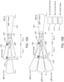
- FIGs. 15A and 15B illustrate situations assuming beam modelling.
- the transmitting node may perform a LBT on a Tx beam direction (e.g., the beam that the transmitting node may use for data transmission towards the receiving node) aligned towards the receiving node direction "dir" and a beamwidth ⁇ Tx (LBT dir ).
- the transmitting node may (e.g., simultaneously) perform: a LBT in a single opposite direction (e.g., LBT dir+180° ) with a beam aligned towards an opposite direction dir+180°, mainlobe beamwidth ⁇ sup , and/or a mainlobe gain G sup,m (as seen in FIG.
- optimization of a beam may be used at transmitting node for LBT in an opposite direction.
- a beam pattern e.g. the mainlobe beamwidth and/or mainlobe gain
- a transmitting node for LBT in opposite (e.g., supplementary paired) direction(s) may be set as a function of a system parameter(s) and/or report(s) from a Receiving node, e.g., when a single opposite direction may be used.
- a number of beams to be used at a transmitting node for a LBT in opposite directions may be determined, e.g., optimized.
- a number of beams to be used at a transmitting node for LBT in opposite (e.g., supplementary paired) directions may be set as a function of system parameters and/or reports from the receiving node. This may occur if multiple opposite (e.g., supplementary paired) directions are used (e.g., when the set of beams at a transmitter is predefined and may not be dynamically modified).
- An example of this is illustrated in FIG. 15B .
- the number of beams for LBT in opposite (e.g., supplementary paired) directions may be set, to maximize the number of solved hidden nodes while the number of exposed nodes remains limited.
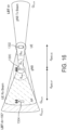
- FIGs. 17A and 17B illustrate examples of an effect of increasing an ED threshold for a LBT in opposite direction(s).
- FIG. 17A illustrates an example of an effect of increasing an ED threshold for a LBT in a single opposite direction with an optimized beam shape, in accordance with some embodiments.
- FIG. 17B illustrates an example of an effect of increasing an ED threshold for a LBT in multiple opposite directions with predefined beams, in accordance with some embodiments.
- FIGs. 17A and 17B A (e.g., optimal) result is depicted in FIGs. 17A and 17B for the case of performing: (a) a single LBT in opposite (e.g., supplementary paired) direction (e.g., 180°, see FIG. 17A ), or (b) multiple LBTs in multiple opposite (e.g., supplementary paired) directions (e.g., 160°, 180°, 200°, see FIG. 17B ).
- opposite (e.g., supplementary paired) direction e.g., 180°, see FIG. 17A
- multiple LBTs in multiple opposite (e.g., supplementary paired) directions e.g., 160°, 180°, 200°, see FIG. 17B .
- TH leg denotes an ED threshold of a LBT in a receiving node direction (which may be -72 dBm in LTE-LAA for a bandwidth of 20 MHz)
- TH sup denotes an ED threshold of the opposite (e.g., supplementary paired) direction(s) (e.g., LBT dir+180 ).
- the farther the receiving node is from a transmitting node e.g., as the transmitter-receiver distance increases
- the more TH sup may be increased.
- an ED threshold for a LBT in opposite direction(s) may be configured to be larger than the one used for a LBT in a receiving node direction (e.g., TH sup > TH leg ). This may occur if the receiving node's information is not available at a transmitting node.
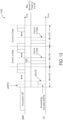
- FIG. 18 is an example flow diagram 1500 for adjusting parameters associated with a LBT in opposite direction(s), in accordance with some embodiments.
- the flow diagram 1500 illustrated in FIG. 18 may apply in the case in which parameters for a LBT in opposite direction(s) are adjusted (e.g., optimally adjusted) based on information from a receiving node and/or system configuration.
- discovery information may include, e.g., characteristics of an Rx beam of the receiving node.
- discovery information may be sent from the receiving to the transmitting node.
- the discovery information may include parameters that are established during a discovery procedure or based on continuing neighboring measurements.
- the parameters may include, e.g., a mainlobe beamwidth and mainlobe gain of an Rx beam of the receiving node.
- parameters of a paired LBT may be dynamically adapted based on a receiver feedback.
- the parameters may be dynamically updated when Rx beam information of a receiving node and/or a transmitter-receiver distance are not known at a transmitting node.
- the adaptation of the LBT parameters for the opposite (e.g., supplementary paired) direction may be done based on the HARQ feedback from a receiving node. In this case, for example, adaptation may be based on statistics for the number of HARQ NACKs received.
- the transmitting node may determine that the receiver node is in an interference-limited scenario and it may: increase the mainlobe beamwidth ( ⁇ sup ) in the opposite (e.g., supplementary paired) direction; use more beams for LBT in opposite direction(s); and/or decrease the ED threshold (TH sup ) for LBT in opposite direction(s), for example to increase the region of detected hidden nodes.
- Transmission from the receiving node to the transmitting node may be prevented, except, for example, to send an ACK/NACK. This may avoid interference generation onto the AP and/or the STA.
- An ED threshold may indicate the power control for a transmission from the receiving node towards the transmitting node.
- a transmitting node may implement an adaptive MCS selection that may depend on the power level sensed in the LBT ED towards the opposite direction(s). For example, if LBT in opposite direction(s) denotes a channel as busy, then, even if channel conditions in transmitter-receiver link are favorable, the transmitting node may transmit at a lower MCS that may be adapted based on the sensed power at LBT in opposite (i.e. supplementary paired) direction(s). This may be performed in a way such that decoding may be possible at a receiving node, even if the receiving node is interfered. Transmission from the transmitting node may be allowed since the transmitting node may not interfering the AP/STA.
- G sup , m C ⁇ sup ⁇ sup
- C may be a constant that depends on the type of 3D antenna pattern (e.g., elliptical, rectangular).
- G sup, m may have a maximum value that depends on the number of antenna elements at the gNB.
- the value of ⁇ Tx (gNB) may be lower than the value of ⁇ Rx (UE), and an adjustment may provide ⁇ sup > ⁇ Tx ( i.e ., a feasible mainlobe beamwidth).
- Uncoordinated LBT mechanism among different nodes of, e.g., the same RAT that can generally implement transmit coordination (or coordination of transmissions between nodes) may result in an unnecessary LBT blocking. It may further result in a poor channel utilization.
- Cellular networks are typically designed to allow a reuse (e.g., a reuse of radio resource(s) (e.g., frequency, time, etc.)), for example, one full reuse, by utilizing a number of interference management techniques (e.g., an adaptive rate control, a power control, a coordinated multi-point (CoMP), an enhanced inter-cell interference coordination (eICIC), etc.) to mitigate an inter-cell interference within the nodes of, e.g., a single RAT (e.g., NR from a specific operator/wireless carrier).
- a reuse e.g., a reuse of radio resource(s) (e.g., frequency, time, etc.)
- interference management techniques e.g., an adaptive rate control, a power control
- LBT blocking may have negative effects as it, for example, prevents a spatial reuse.
- a spatial reuse refers to enabling time and frequency resource utilization in different locations.
- interfering beams may hinder (e.g., due to collisions) a spatial reuse of radio resources.
- a gNB e.g., the gNB1 shown in FIG. 25B
- the gNB could send a message over to that node, e.g., via an Xn interface as in NR (or an X2 interface as in LTE) to request a LBT coordination (referred to herein as "LBT-C-RQ") in an effort to avoid unnecessary LBT blocking.
- FIG. 26 illustrates an example of a scenario of LBT coordination, in accordance with some embodiments.
- a detection of the presence of device(s) of the same RAT may be based on an assumption that nodes of the same RAT will generally be able to decode their own RAT messages (e.g., a PDCCH or eDRTS (enhanced directional RTS)).
- a PDCCH or eDRTS enhanced directional RTS
- transmit coordination may be performed in multiple domains, such as time, frequency, space, power, and/or rate. However, note that, in some embodiments, some level and/or form of transmit coordination may be needed to complete the LBT backoff procedure. In some embodiments, the LBT coordination may be either in a frequency domain or a time domain.
- FIGs. 27A and 27B illustrate, respectively, examples of a LBT coordination in (A) frequency-domain and (B) time-domain, in accordance with some embodiments.
- an example procedure to complete a LBT backoff and subsequently use any suitable transmit coordination strategy for transmission may be, by way of example, as follows.
- a gNB2 upon receipt of a LBT-C-RQ 2400 and, e.g., an indication of a backoff time from a gNB1, may release some resource blocks (RBs) or a BWP (bandwidth part) for a certain period, and may indicate so to a gNB1 through a frequency-related coordination acceptance (message) 2402 (referred to herein as "LBT-C-A-f").
- the gNB2 may also provide, for example, indication(s) of parameters such as, but not limited to, released resources, a transmit coordination strategy, a start time for transmit coordination, and/or a time-to-MCOT limit.
- the gNB1 upon receipt of the information/message(s) from the gNB2, may change from a wide-band LBT to a BWP LBT (or sub-band LBT) within the indicated frequency resource(s) (or BWP) released by the gNB2.
- a release of some RBs and the gNB1 having an ability to implement the BWP LBT in those RBs may (i) enable the gNB1 to complete the LBT backoff procedure in accordance with applicable unlicensed spectrum regulation(s), and (ii) subsequently transmit by exploiting a spatial reuse (e.g., by fully exploiting the spatial reuse within an allocated BWP).
- an example procedure to complete a LBT backoff (b)), and subsequently use any suitable transmit coordination strategy for transmission may be, by way of example as follows
- a time remaining in the backoff (e.g., at the gNB1) may be concurrently or jointly sent with the LBT-C-RQ 2400 and/or 2404, respectively, so that the gNB2 can properly configure the released resources (e.g., a BWP or some temporal symbols) for the gNB1 to complete a LBT.
- the BWP that is released and/or the temporal symbol(s) that are released to complete the back-off are specified, as well as the information about the start time plus coordination strategy that, e.g., may permit full reuse plus end time (MCOT limit).
- some embodiments described herein may not only provide for a spatial reuse but may also reduce a channel access delay.
- a coordinated LBT Enabled Signaling (referred to herein as "LBTES") is disclosed.
- the LBTES may be sent through Xn by a gNB that occupies the channel and receives the LBTRS.
- the LBTES may include the following (but not limited to) information: (i) a frequency-domain LBT coordination acceptance to complete a backoff (LBT-C-A-f), (ii) released resources in a frequency domain (e.g., BWP), (iii) a time-domain LBT coordination acceptance to complete a backoff (LBT-C-A-t), (iv) a start time of a transmit coordination, (iv) a transmit coordination strategy (time, freq, power, space, CoMP,etc.), (v) a time to MCOT limit, (vi) a requesting gNB identification, and/or (vii) a requested gNB identification.
- LBT-C-A-f frequency-domain LBT coordination acceptance to complete a backoff
- the use of the requesting gNB identification (e.g., an ID of a gNB1) and a requested gNB identification (e.g., an ID of a gNB2) in, e.g., the LBTRS enable the coordination between specific gNBs, rather than being directed towards, e.g., all of the nodes (e.g., all of gNBs) of a given RAT.
- some embodiments disclosed herein may provide signaling to request for coordination of LBT backoff procedures (either in time or in frequency (e.g., a BWP)) after, e.g., detecting ongoing transmissions of TRPs of the same RAT that can be coordinated for transmission.
- LBT backoff procedures either in time or in frequency (e.g., a BWP)
- some embodiments disclosed herein provide ways to ensure fairness among different RATs in unlicensed band/spectrum.
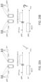
- FIG. 28A illustrates an example of a behavior of an omnidirectional LBT, in accordance with some embodiments.
- FIG. 28B illustrates an example of a behavior of a directional LBT for directional transmissions/receptions, in accordance with some embodiments.
- a directional LBT may not create overprotection because it may typically only sense a spatial direction in which a transmission will be carried out (see FIG. 28B (top) (a case 2454 of non-aligned transmissions)).
- FIG. 28B (top) a case 2454 of non-aligned transmissions
- FIG. 28B (bottom) a case 2456 of aligned transmissions
- the best physical carrier sense scheme from among a directional LBT, a paired LBT (also referred to herein as "pairLBT"), and an omni directional LBT) (at least in terms of performance) varies in accordance with a network density and employed beamwidths. For example, for a low network density, a directional LBT may be enough, while for a high network density, an omnidirectional LBT may be enough. Similarly, for narrow beamwidths, a directional LBT may be enough, while for wide beamwidths, an omnidirectional LBT may be enough. Additionally, a complexity of a given LBT mode maybe taken into account when selecting a LBT mode. Generally, an omnidirectional LBT, e.g., may be considered to be the simplest one.
- methods and systems disclosed herein provide a LBT switching mechanism that addresses at least some of the shortcomings associated with, for example, the use of omnidirectional LBT and/or directional LBT in cases of directional transmissions and receptions, as illustrated in FIGs. 28A and 28B .
- switching from a directional LBT to an omnidirectional LBT may be done when the directional LBT senses a channel as idle, but a hidden node problem arises.
- the switching may be performed based on HARQ-ACK feedback. For example, if multiple HARQ-ACK feedbacks are NACKs, then a transmitting node (TX) may switch to an omnidirectional LBT. Otherwise, it may continue with the directional LBT.
- TX transmitting node
- a NACK may typically be determined either when an incorrect reception arises (e.g., a control channel was decoded but data could not be decoded) or when no feedback is received (e.g., a control channel could not be decoded, or a NACK feedback was not correctly decoded or blocked, e.g., due to a LBT).
- Switching from a directional LBT to an omnidirectional LBT may be implemented based, e.g., on information such as a HARQ-ACK feedback. More specifically, in some embodiments, the transmitting node may average the collected information for a DL (downlink) case. In one example embodiment, the transmitting node in the DL case, such as a gNB, may collect HARQ-ACK feedback from a UE, and may determine to switch from a directional LBT to an omnidirectional LBT when a number of NACKs exceeds a particular threshold within a given time period or over a certain number of received HARQ feedbacks.
- switching from an omnidirectional LBT to a directional LBT may be done when the omniLBT prevents a number (e.g., a predetermined number or a number exceeding a certain threshold) of accesses to a channel, such as due to exposed nodes rather than due to interference situations.
- the LBT switching may be performed based on reported information from a receiving node (RX) according to the following example mechanism described below.
- a TX transmitting node
- the TX may send information to the RX regarding the time instants of prevented channel accesses.
- the RX may perform a continuous ED (energy detection) carrier sense, with an antenna configuration or beam that it would normally use for data reception from TX, while in a Radio Resource Control (RRC) connected mode, and may save result(s) in memory.
- RRC Radio Resource Control
- the RX may compare those time instants with the results of the ED carrier sense and respond to the TX if the RX senses signal energy larger than a threshold using the antenna configuration or beam that is used for the data reception from the TX.
- FIG. 29 illustrates a procedure 2500 for an omnidirectional LBT overprotective detection, in accordance with some embodiments.
- Such procedure may involve, by way of example, the following: (i) sensing information 2506 transmitted from a transmitting node 2502 (also denoted as "TX"), e.g., slot and/or OFDM symbol (OS) indexes in which a channel access was attempted (and found busy)( ⁇ x, y, z ⁇ , as, e.g., shown in FIG. 29 ); and/or (ii) a response 2508 to the sensing information 2506 sent from a receiving node 2504 (also denoted as "RX").
- TX transmitting node 2502
- OS OFDM symbol
- multiple response options may be available, some examples of which include one or more of the following: (1) slot/OS indexes in which a sensed node was detected, (2) a percentage of attempts 2508 (as shown in FIG. 29 ) during which the channel was found busy on the RX side, and/or (3) a switching (or switch) indicator 2510 (as shown in FIG. 29 ).
- the RX may respond to the TX with a value that includes this information as, e.g., a percentage or fraction (see, e.g., the percentage 2508 in FIG. 29 (left side)) or may send a switch indicator (see, e.g., the switch indicator 2510 in FIG. 29 (right side)) to inform the TX to switch a LBT mode.
- a percentage or fraction see, e.g., the percentage 2508 in FIG. 29 (left side)
- a switch indicator see, e.g., the switch indicator 2510 in FIG. 29 (right side)
- reporting (3) has a lower overhead but provides less detailed information on a TX side (e.g., a UE side) than (1) and (2).
- a base station e.g., an eNB
- the UE reports based on formats (1) and (2) may provide additional information to the base station, relative to format (3), to make the switch decision, but use of these UE report formats may, e.g., require a higher signaling overhead than (3).
- a number of switching indicators received may be, e.g., required to exceed a particular threshold in order to perform the switching.
- the TX e.g., a UE
- the TX may communicate with different TRPs through different beams
- reporting (1), (2), and/or (3) may be equivalent because no averaging is required at the TX (e.g., a UE).
- proposed mechanisms used to switch LBT strategy may, for example, include a switch (i) from an omniLBT to a pairLBT (a soft change), (ii) from an omniLBT to a dirLBT (a drastic change, if it is determined that the omniLBT results in more missed channel access occasions than necessary) or (iii) from a pairLBT to a dirLBT.
- CWS contention window size
- a CWS is updated based on HARQ feedbacks. If, e.g., 80% of HARQ feedbacks of one reference subframe is a NACK, the CWS is increased; otherwise it is not. It may be desirable to implement some form of a CWS adaptation procedure based on observed (data) collisions in a NR-U framework. However, in a case of, for example, a directional transmission, CWS adaptation procedure(s) adapted for use in LAA may not be appropriate and different CWS adaptation procedure(s) may, e.g., be needed.
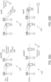
- FIGs. 30A and 30B illustrate examples of a CWS adaptation in multi-cell scenarios.
- LBTs represented by respective beams 2604 and 2606 of a gNB 2600 and a gNB 2602 (also denoted as “gNB1" and "gNB2", respectively) are not aligned and both gNBs 2600 and 2602 may listen to a channel during a DIFS. Since a transmission of one gNB may not or cannot be heard by the other gNB, the channel is sensed free for both of the gNBs 2600 and 2602. Therefore, both gNBs access the channel substantially at the same time, and a collision results.
- both gNBs may exponentially increase the CWS. Both gNBs listen again during a DIFS, sense the channel to be free again, and another collision occurs. Hence, the same procedure will continue repeatedly. In such case, since LBTs are not aligned (as shown in FIG. 30A ), increasing the CWS based on HARQ procedure may not be appropriate.
- the described CWS adaptation procedure may, e.g., only be appropriate for a scenario shown in FIG. 30B , when respective LBTs (represented by respective beams 2608 and 2610) of both of the gNBs 2600 and 2602 are aligned. If the gNBs 2600 and 2602 see each other, they likely would backoff and randomize their channel access by adapting their respective CWS.
- a CWS adaptation at a gNB may be based on a statistical paired sensing at a targeted UE, in a direction of a transmitting beam. This may include channel sensing in a direction of a receive beam and also in the opposite direction that is intended to cover the gNB transmit beam direction.
- the targeted UE may suggest the most appropriate CWS over the transmission beam line, based, for example, on a percentage of busy slots sensed during a sensing phase.
- a CWS adaptation based on, e.g., HARQ NACKs/ACKs may be used, if, for instance, the NACK includes directional information from sensing, indicating whether a source of interference aligned with a transmission beam exists, where such source may have caused a collision.
- a transmission at mmW frequencies may, e.g., require a directional Tx-Rx (transmit-receive) operation.
- transmissions at unlicensed frequencies may, e.g., require channel sensing to determine if the channel is free.
- Simply performing, e.g., a directional LBT and a RTS/CTS in a direction of the intended transmission/reception, may in some implementations not be sufficient to correctly determine a channel utilization status due to, e.g., a potential existence of directional hidden nodes.
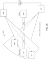
- FIG. 35 illustrates an example scenario 2850 involving directional RTS/CTS in NR-U to NR-U coexistence in the presence of interfering nodes.
- methods and systems disclosed herein in accordance with some embodiments address challenges relating to how to reserve an unlicensed channel using directional Tx-Rx in the presence of hidden nodes.
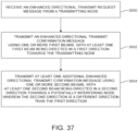
- FIG. 36 is a flow chart illustrating a method for reserving a directional channel, in accordance with some embodiments.
- the method may be performed by a receiving node, such a wireless transmit/receive unit (e.g., a UE).
- a receiving node such a wireless transmit/receive unit (e.g., a UE).
- the receiving node receives a directional Request-to-Send (DRTS) message from a transmitting node.
- DRTS Request-to-Send
- DCTS Clear-to-Send
- an enhanced directional messaging e.g., an eDCTS and/or an eDCTS-to-Self message
- an eDRTS may contain scheduling information of data and an eDCTS-to-Self and/or interfering node locations and orientations.
- an eDCTS-to-Self may be targeted towards direction(s) of, e.g., potentially (e.g., known) interfering node(s) (e.g. obtained from a gNB or via measurement(s)).
- the eDCTS-to-Self transmission may be repeated once every T (or every given time period) (e.g., based on a minimum CCA duration).
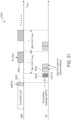
- the eDCTS-to-Self may contain remaining MCOT duration information. Referencing FIG. 31 , for example, a MCOT may, e.g., begin just prior to an eDRTS being sent or just after a (e.g., successful) LBT and may include multiple periods T.
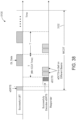
- FIG. 38 illustrates an example of a series of transmissions 3100, including eDRTS and eDCTS-to-Self transmissions, in accordance with some embodiments.
- FIG. 38 shows an example of MCOT duration 3102 and periodic eDCTS-to-Self transmissions within the MCOT.
- a method performed by a UE to reserve a channel may include: receiving an enhanced directional request-to-send (eDRTS) message from a transmitting node; transmitting an enhanced directional clear-to-send (eDCTS) message in a first direction toward the transmitting node; and transmitting an additional eDCTS message in a second direction toward a potentially interfering node.
- eDRTS enhanced directional request-to-send
- eDCTS enhanced directional clear-to-send
- a method of addressing, at a receiving device, a potential interference from one or more potentially hidden network nodes during directional transmission and reception between the receiving node and a transmitting node at unlicensed frequencies may include the receiving node performing a directional channel access using enhanced messaging in multiple directions to reserve a directional channel between the receiving node and the transmitting node.
- the receiving node is a UE
- the transmitting node is a base station (e.g., a gNB).
- the first and second directions are different and at least one of the first and the second directions is a direction towards a potentially interfering node.
- the direction towards the potentially interfering node may be indicated by the first type of message.
- the second type of message is an enhanced Directional Clear-To-Send-to-Self (eDCTS-to-Self) message.
- the second type of message is an eDCTS, and the eDCTS may be sent repeatedly multiple times by the device within a given time duration, such as a maximum channel occupancy time (MCOT).
- MCOT maximum channel occupancy time
- a method performed at a transmitting node includes: performing a first listen-before-talk (LBT) in a direction of a transmitting beam towards a receiving node; determining if a channel is busy based on the performed first LBT in the direction of the transmitting beam; performing a second LBT in a reverse direction; and determining if an interfering signal is detected from the reverse direction.
- the method may further include deferring a transmission if the interfering signal is detected. Deferring the transmission may, for example, include waiting a backoff time and performing the first and second LBTs again.
- various parameters including for example, a configuration of a beam width, a number of predefined beams, an energy detection threshold, and/or MCS selection for a communication link may be adaptively chosen.
- the first and second nodes may be associated with a given radio access technology (RAT), such as the same RAT, and/or with a given operator, such as the same operator. Further, the first and second nodes may be coordinated for transmission in an unlicensed band, such as, e.g., a 5 GHz or 60 GHz band. In yet other embodiments, the method for the coordinated LBT signaling may further include providing, by the first node, to the second node at least one of a start time for transmit coordination and a transmit coordination strategy to be used after the LBT backoff is completed.
- RAT radio access technology
- the method for the coordinated LBT signaling may further include providing, by the first node, to the second node at least one of a start time for transmit coordination and a transmit coordination strategy to be used after the LBT backoff is completed.
- a method includes providing signaling associated with a listen-before-talk (LBT) coordination that is suitable for use over a 5G Xn interface.
- the signaling associated with the LBT coordination may include a coordinated LBT request signaling (LBTRS).
- LBTRS may be sent over the Xn interface by, e.g., a gNB detecting a busy channel due to a presence of a node that shares a radio access technology (RAT) with the gNB.
- RAT radio access technology
- the at least two different types of LBT may include an omnidirectional LBT and a directional LBT.
- the switching may include switching (i) from an omnidirectional LBT to a paired LBT, (ii) from an omnidirectional LBT to a directional LBT, or (iii) from a paired LBT to a directional LBT.
- a method of modifying a contention window size (CWS) for directional transmissions includes a user device, such as, e.g., a user equipment (UE), requesting a backoff from a base station, such as, e.g., a gNB.
- a user device such as, e.g., a user equipment (UE)
- UE user equipment
- a base station such as, e.g., a gNB.
- a method of modifying a contention window size (CWS) for directional transmissions at a base station e.g., a gNB
- Such method is based on a paired sensing at a targeted user device (e.g., a user equipment (UE)).
- UE user equipment
Landscapes
- Engineering & Computer Science (AREA)
- Computer Networks & Wireless Communication (AREA)
- Signal Processing (AREA)
- Mobile Radio Communication Systems (AREA)
Applications Claiming Priority (4)
| Application Number | Priority Date | Filing Date | Title |
|---|---|---|---|
| US201762574548P | 2017-10-19 | 2017-10-19 | |
| US201862689046P | 2018-06-22 | 2018-06-22 | |
| EP18800377.6A EP3698599B1 (de) | 2017-10-19 | 2018-10-17 | Kanalzugangsverfahren für richtungssysteme in unlizenzierten bändern |
| PCT/US2018/056353 WO2019079500A1 (en) | 2017-10-19 | 2018-10-17 | CHANNEL ACCESS PROCEDURES FOR DIRECTIONAL SYSTEMS IN BANDS WITHOUT LICENSE |
Related Parent Applications (2)
| Application Number | Title | Priority Date | Filing Date |
|---|---|---|---|
| EP18800377.6A Division EP3698599B1 (de) | 2017-10-19 | 2018-10-17 | Kanalzugangsverfahren für richtungssysteme in unlizenzierten bändern |
| EP18800377.6A Division-Into EP3698599B1 (de) | 2017-10-19 | 2018-10-17 | Kanalzugangsverfahren für richtungssysteme in unlizenzierten bändern |
Publications (2)
| Publication Number | Publication Date |
|---|---|
| EP4398495A2 true EP4398495A2 (de) | 2024-07-10 |
| EP4398495A3 EP4398495A3 (de) | 2024-10-16 |
Family
ID=64267911
Family Applications (2)
| Application Number | Title | Priority Date | Filing Date |
|---|---|---|---|
| EP18800377.6A Active EP3698599B1 (de) | 2017-10-19 | 2018-10-17 | Kanalzugangsverfahren für richtungssysteme in unlizenzierten bändern |
| EP24177702.8A Pending EP4398495A3 (de) | 2017-10-19 | 2018-10-17 | Kanalzugriffsverfahren für richtungssysteme in unlizenzierten bändern |
Family Applications Before (1)
| Application Number | Title | Priority Date | Filing Date |
|---|---|---|---|
| EP18800377.6A Active EP3698599B1 (de) | 2017-10-19 | 2018-10-17 | Kanalzugangsverfahren für richtungssysteme in unlizenzierten bändern |
Country Status (5)
| Country | Link |
|---|---|
| US (2) | US11497056B2 (de) |
| EP (2) | EP3698599B1 (de) |
| JP (3) | JP7277448B2 (de) |
| CN (2) | CN111480388B (de) |
| WO (1) | WO2019079500A1 (de) |
Cited By (1)
| Publication number | Priority date | Publication date | Assignee | Title |
|---|---|---|---|---|
| US20250193928A1 (en) * | 2023-12-08 | 2025-06-12 | Apple Inc. | Directional Listen Before Talk for sub-THz Access Points |
Families Citing this family (77)
| Publication number | Priority date | Publication date | Assignee | Title |
|---|---|---|---|---|
| TWI720052B (zh) * | 2015-11-10 | 2021-03-01 | 美商Idac控股公司 | 無線傳輸/接收單元和無線通訊方法 |
| CN111133787B (zh) * | 2017-11-28 | 2021-09-24 | 上海朗帛通信技术有限公司 | 一种被用于无线通信的用户设备、基站中的方法和装置 |
| CN110062395B (zh) * | 2018-01-18 | 2020-10-30 | 维沃移动通信有限公司 | 用于信道侦听的方法和通信设备 |
| US10912128B2 (en) * | 2018-01-23 | 2021-02-02 | Samsung Electronics Co., Ltd. | Listen-before-talk for wideband operations of NR unlicensed spectrum |
| US11457475B2 (en) * | 2018-02-14 | 2022-09-27 | Idac Holdings, Inc. | Methods, apparatus, and system using multiple antenna techniques for new radio (NR) operations in unlicensed bands |
| CN112737752B (zh) * | 2018-02-14 | 2022-07-12 | 华为技术有限公司 | 一种确定竞争窗大小的方法和装置 |
| CN110167077A (zh) * | 2018-02-14 | 2019-08-23 | 华为技术有限公司 | 一种发送资源预留消息的方法及装置 |
| WO2019157753A1 (zh) * | 2018-02-14 | 2019-08-22 | Oppo广东移动通信有限公司 | 侦听方法和设备 |
| US11582797B2 (en) * | 2018-04-05 | 2023-02-14 | Lg Electronics Inc. | Method and device for mitigating interference in unlicensed band |
| KR20210003171A (ko) * | 2018-04-25 | 2021-01-11 | 광동 오포 모바일 텔레커뮤니케이션즈 코포레이션 리미티드 | 신호 전송 방법 및 통신 기기 |
| KR102574099B1 (ko) * | 2018-07-24 | 2023-09-04 | 주식회사 아이티엘 | 차량 통신을 지원하는 무선통신 시스템에서 무선 통신을 수행하는 방법 및 그 장치 |
| US11595823B2 (en) * | 2018-07-25 | 2023-02-28 | Qualcomm Incorporated | Medium reservation using energy detection and receiver assisted clear channel assessment |
| CN112703813B (zh) * | 2018-09-13 | 2023-11-21 | 索尼集团公司 | 用于增强型通信的方法和设备 |
| GB2577867B (en) * | 2018-09-28 | 2022-10-26 | Tcl Communication Ltd | Conflict avoidance in a cellular network |
| CN109699085A (zh) * | 2018-10-17 | 2019-04-30 | 华为技术有限公司 | 一种传输数据的方法以及终端设备 |
| WO2020089709A1 (en) * | 2018-11-02 | 2020-05-07 | Telefonaktiebolaget Lm Ericsson (Publ) | Adaptive sensing mechanism for unlicensed networks |
| US11382129B2 (en) * | 2018-11-08 | 2022-07-05 | Acer Incorporated | Device and method for handling channel access procedure |
| US11115110B2 (en) * | 2018-12-14 | 2021-09-07 | Qualcomm Incorporated | Default beam selection based on a subset of coresets |
| US11324041B2 (en) * | 2018-12-14 | 2022-05-03 | Qualcomm Incorporated | Signaling of default and scheduled beam in cot |
| KR102811191B1 (ko) * | 2018-12-26 | 2025-05-22 | 삼성전자주식회사 | 무선 통신 시스템에서 방향을 추정하기 위한 장치 및 방법 |
| US11381981B2 (en) * | 2019-01-31 | 2022-07-05 | Qualcomm Incorporated | Listen-before-talk schemes for directional communications |
| US11395154B2 (en) * | 2019-04-18 | 2022-07-19 | Qualcomm Incorporated | Methods and apparatuses for determining sensing beam for an LBT procure |
| JP7642303B2 (ja) * | 2019-04-24 | 2025-03-10 | キヤノン株式会社 | 通信装置、制御方法、及び、プログラム |
| US11882461B2 (en) * | 2019-07-08 | 2024-01-23 | Qualcomm Incorporated | Bidirectional listen-before-talk operation |
| EP4669006A3 (de) * | 2019-08-14 | 2026-03-18 | Koninklijke Philips N.V. | Vorrichtungen und verfahren für drahtlose kommunikation |
| CN114402692B (zh) * | 2019-08-16 | 2025-03-14 | 交互数字专利控股公司 | mmW操作中的非许可频谱的信道接入 |
| WO2021033880A1 (ko) * | 2019-08-19 | 2021-02-25 | 엘지전자 주식회사 | 저지연을 위한 ofdma 랜덤 액세스 방법 |
| WO2021038121A1 (en) * | 2019-08-27 | 2021-03-04 | Nokia Technologies Oy | Channel access for wireless communications |
| EP3959928B1 (de) * | 2019-09-13 | 2024-10-30 | Aalyria Technologies, Inc. | Weiterreichungskoordination für grossflächige versorgung |
| US11184265B2 (en) * | 2019-10-16 | 2021-11-23 | Cisco Technology, Inc. | Inter-protocol interference reduction for hidden nodes |
| CN113141618A (zh) * | 2020-01-20 | 2021-07-20 | 索尼公司 | 电子设备、无线通信方法和计算机可读存储介质 |
| US12531626B2 (en) * | 2020-01-27 | 2026-01-20 | Qualcomm Incorporated | Asymmetric uplink-downlink beam training in frequency bands |
| US11856570B2 (en) | 2020-01-27 | 2023-12-26 | Qualcomm Incorporated | Dynamic mixed mode beam correspondence in upper millimeter wave bands |
| US12407385B2 (en) | 2020-01-27 | 2025-09-02 | Qualcomm Incorporated | Signaling of beam correlation across millimeter wave frequency bands |
| US11831383B2 (en) | 2020-01-27 | 2023-11-28 | Qualcomm Incorporated | Beam failure recovery assistance in upper band millimeter wave wireless communications |
| EP4097870A1 (de) | 2020-01-27 | 2022-12-07 | Qualcomm Incorporated | Antennengruppenauswahl und -anzeige in frequenzbändern |
| US12401403B2 (en) | 2020-01-27 | 2025-08-26 | Qualcomm Incorporated | Antenna group-specific parameter configuration in millimeter wave communications |
| CN113225814B (zh) | 2020-02-04 | 2022-11-01 | 上海朗帛通信技术有限公司 | 一种被用于无线通信的节点中的方法和装置 |
| EP4101194A1 (de) * | 2020-02-06 | 2022-12-14 | Telefonaktiebolaget LM Ericsson (publ) | Empfängerunterstützte richtungsabhängige kanalabtastung für nr-u |
| US12374787B2 (en) | 2020-02-11 | 2025-07-29 | Qualcomm Incorporated | Adjusting communications operations for changes to configurations for quasi co-location and number of antenna elements |
| US11764855B2 (en) * | 2020-02-12 | 2023-09-19 | Qualcomm Incorporated | Managing beam selection |
| WO2021159520A1 (en) * | 2020-02-14 | 2021-08-19 | Nokia Shanghai Bell Co., Ltd. | Apparatus, method and computer program |
| CN111405678B (zh) * | 2020-02-19 | 2023-02-17 | 重庆邮电大学 | 一种基于虚拟载波侦听和优先级调度的csma-ca方法 |
| US12177896B2 (en) * | 2020-03-17 | 2024-12-24 | Qualcomm Incorporated | Proxy sensing-based channel access for shared spectrum |
| WO2021207448A1 (en) * | 2020-04-08 | 2021-10-14 | Gogo Business Aviation Llc | Systems and methods to control access in air-to-ground networks operating in unlicensed spectrum |
| CN113543141B (zh) * | 2020-04-21 | 2024-06-04 | 维沃移动通信有限公司 | 传输确认方法、终端设备及传输节点 |
| CN113541860B (zh) * | 2020-04-22 | 2023-08-22 | 维沃移动通信有限公司 | 控制信令格式确定方法、指示方法及设备 |
| CN113556826B (zh) * | 2020-04-24 | 2022-07-01 | 上海朗帛通信技术有限公司 | 一种被用于无线通信的节点中的方法和装置 |
| US11792666B2 (en) | 2020-06-04 | 2023-10-17 | Qualcomm Incorporated | Location assistance data for wideband positioning |
| US12476685B2 (en) * | 2020-06-18 | 2025-11-18 | Beijing Xiaomi Mobile Software Co., Ltd. | Information transmission method and apparatus, communication device, and storage medium |
| CN115885535B (zh) * | 2020-06-29 | 2026-03-24 | 株式会社Ntt都科摩 | 无线基站、终端以及通信方法 |
| WO2022021293A1 (zh) * | 2020-07-31 | 2022-02-03 | Oppo广东移动通信有限公司 | 信道侦听的方法及设备 |
| CN114070362B (zh) * | 2020-08-03 | 2023-04-07 | 上海朗帛通信技术有限公司 | 一种被用于无线通信的节点及其方法 |
| WO2022027227A1 (zh) * | 2020-08-04 | 2022-02-10 | 深圳传音控股股份有限公司 | 干扰消除方法、设备和计算机可读存储介质 |
| US11956818B2 (en) * | 2020-08-06 | 2024-04-09 | Samsung Electronics Co., Ltd. | Multi-beam LBT for NR-U at 60 GHz |
| CN115669173B (zh) * | 2020-10-14 | 2025-11-25 | 中兴通讯股份有限公司 | 用于无线通信的方法、设备和计算机程序产品 |
| CN116368856A (zh) * | 2020-10-14 | 2023-06-30 | 瑞典爱立信有限公司 | 用于通信管理的方法和装置 |
| US20230413068A1 (en) * | 2020-10-15 | 2023-12-21 | Panasonic Intellectual Property Corporation Of America | Wireless apparatus and wireless method |
| US11627606B2 (en) * | 2020-10-16 | 2023-04-11 | Samsung Electronics Co., Ltd | Receiver-assisted listen before talk for new radio unlicensed spectrum |
| US11516844B2 (en) * | 2020-10-22 | 2022-11-29 | Telefonaktiebolaget Lm Ericsson (Publ) | Beamforming in listen-before-talk environments |
| US12013478B2 (en) * | 2020-10-26 | 2024-06-18 | Qualcomm Incorporated | Timing for listen before talk for radar |
| WO2022154406A1 (ko) | 2021-01-15 | 2022-07-21 | 엘지전자 주식회사 | 채널 접속 절차를 수행하는 방법 및 이를 위한 장치 |
| WO2022164597A1 (en) * | 2021-01-29 | 2022-08-04 | Qualcomm Incorporated | Transmit receive point directional transmission for channel sensing |
| US12058735B2 (en) | 2021-01-29 | 2024-08-06 | Qualcomm Incorporated | Transmit receive point directional transmission for channel sensing |
| WO2022165715A1 (zh) * | 2021-02-04 | 2022-08-11 | 北京小米移动软件有限公司 | 一种非授权信道的检测方法、装置、设备及存储介质 |
| US12041658B1 (en) * | 2021-03-24 | 2024-07-16 | Meta Platforms Technologies, Llc | Systems and methods for performing coexistence operations in wireless spectrums |
| WO2022200825A1 (en) * | 2021-03-26 | 2022-09-29 | Orope France Sarl | Apparatus and method of wireless communication |
| WO2022205298A1 (en) * | 2021-04-01 | 2022-10-06 | Qualcomm Incorporated | Selective receiver-assisted channel sensing |
| CN113489556B (zh) * | 2021-07-08 | 2023-07-28 | 维沃移动通信有限公司 | 信号接收方法、装置、电子设备和存储介质 |
| JP2024535707A (ja) * | 2021-09-01 | 2024-10-02 | インターデイジタル パテント ホールディングス インコーポレイテッド | サイドリンクリソース割り当て用の方法、アーキテクチャ、装置及びシステム |
| JP7804373B2 (ja) | 2022-02-14 | 2026-01-22 | ウィルス インスティテュート オブ スタンダーズ アンド テクノロジー インコーポレイティド | 無線通信システムにおいて信号を送信する方法及び装置 |
| US12557137B2 (en) | 2022-08-01 | 2026-02-17 | Qualcomm Incorporated | Channel occupancy sharing conditions for beam-based channel access |
| US12402168B2 (en) * | 2022-08-15 | 2025-08-26 | Qualcomm Incorporated | Techniques for normalizing narrow beam channel access parameters based on bandwidth in wireless communications |
| EP4643565A4 (de) * | 2022-12-27 | 2026-02-18 | Rakuten Symphony Inc | Systeme und verfahren zur optimierung der antennenneigung an einem zellularen standort |
| US20250056608A1 (en) * | 2023-08-08 | 2025-02-13 | Qualcomm Incorporated | Techniques for full-duplex channel access in shared radio frequency spectrum |
| US20250193929A1 (en) * | 2023-12-08 | 2025-06-12 | Apple Inc. | Flexible Frame Structures for Directional Unlicensed Access in Sub-Terahertz Band |
| CN118301782B (zh) * | 2024-03-29 | 2024-12-31 | 重庆赛力斯凤凰智创科技有限公司 | 一种多路访问方法和装置 |
Family Cites Families (23)
| Publication number | Priority date | Publication date | Assignee | Title |
|---|---|---|---|---|
| JP2002057677A (ja) | 2000-08-09 | 2002-02-22 | Nippon Telegr & Teleph Corp <Ntt> | 無線パケット送信方法 |
| US6611231B2 (en) * | 2001-04-27 | 2003-08-26 | Vivato, Inc. | Wireless packet switched communication systems and networks using adaptively steered antenna arrays |
| US7075902B2 (en) * | 2002-02-11 | 2006-07-11 | Hrl Laboratories, Llc | Apparatus, method, and computer program product for wireless networking using directional signaling |
| CN1567869B (zh) * | 2003-06-30 | 2010-05-05 | 叶启祥 | 可避免干扰损坏并增加空间再用率的干扰控制方法 |
| KR101042763B1 (ko) | 2005-07-07 | 2011-06-20 | 삼성전자주식회사 | 이기종 시스템 간의 핸드오버 방법 및 장치 |
| US8897268B2 (en) | 2008-03-11 | 2014-11-25 | Intel Corporation | Apparatus and method adapted for directional bandwidth reservation with fixed announcement slot in wireless networks |
| US9066267B2 (en) | 2008-08-29 | 2015-06-23 | Intel Corporation | Device, method and system of establishing a protected time during an allocated time |
| US8730873B2 (en) * | 2008-11-04 | 2014-05-20 | Nokia Corporation | Asymmetric beam steering protocol |
| DK2540108T3 (da) | 2010-02-24 | 2014-09-01 | Interdigital Patent Holdings | Kommunikation ved hjælp af retningsbestemte antenner |
| CN103052077B (zh) * | 2012-12-18 | 2015-09-16 | 东南大学 | 一种无线局域网obss站点空分干扰避免方法 |
| CN104639289B (zh) * | 2015-01-28 | 2018-01-30 | 西安电子科技大学 | 一种wlan中空闲节点辅助的定向接入控制方法 |
| JP6488424B2 (ja) | 2015-08-06 | 2019-03-20 | テレフオンアクチーボラゲット エルエム エリクソン(パブル) | リスニングベースの送信のための方法および装置 |
| US10129870B2 (en) | 2015-09-01 | 2018-11-13 | Qualcomm Incorporated | Separation of control and data subbands in unlicensed spectrum |
| CN113014367B (zh) | 2015-10-12 | 2024-05-31 | 纽瑞科姆有限公司 | 用于无线传输的保护方法 |
| US10362586B2 (en) * | 2015-10-13 | 2019-07-23 | Futurewei Technologies, Inc. | System and method for spatial reuse in directional random access |
| EP3400745B1 (de) * | 2016-01-06 | 2024-10-02 | Apple Inc. | Verfahren und vorrichtung für kanalzugriff zur übertragung von pusch- und ul-steuerung |
| WO2017132840A1 (en) | 2016-02-02 | 2017-08-10 | Nec Corporation | Methods and apparatuses for performing uplink scheduling and ul transmission |
| MX389732B (es) * | 2016-02-05 | 2025-03-11 | Ericsson Telefon Ab L M | Eschuchar antes de hablar para transmision de enlace ascendente. |
| KR102307242B1 (ko) * | 2016-05-20 | 2021-09-30 | 텔레호낙티에볼라게트 엘엠 에릭슨(피유비엘) | 비면허 스펙트럼에서의 다수의 서브프레임들의 스케줄링 |
| CN107888256B (zh) | 2016-09-30 | 2022-12-02 | 中兴通讯股份有限公司 | 数据传输、接收方法、装置、基站及终端 |
| US10257848B2 (en) * | 2016-10-04 | 2019-04-09 | Qualcomm Incorporated | Directional channel reservation for time-division multiplexing downlink and uplink data burst transmission |
| US10645727B2 (en) * | 2016-12-28 | 2020-05-05 | Qualcomm Incorporated | Directional reception and periodic RTS/CTS transmission to estimate interference |
| US11277865B2 (en) * | 2017-05-30 | 2022-03-15 | Huawei Technologies Co., Ltd. | Methods and system for LBT threshold setting for directional reception and transmission |
-
2018
- 2018-10-17 WO PCT/US2018/056353 patent/WO2019079500A1/en not_active Ceased
- 2018-10-17 JP JP2020521462A patent/JP7277448B2/ja active Active
- 2018-10-17 EP EP18800377.6A patent/EP3698599B1/de active Active
- 2018-10-17 US US16/754,355 patent/US11497056B2/en active Active
- 2018-10-17 CN CN201880079232.7A patent/CN111480388B/zh active Active
- 2018-10-17 CN CN202311492388.7A patent/CN117767986A/zh active Pending
- 2018-10-17 EP EP24177702.8A patent/EP4398495A3/de active Pending
-
2022
- 2022-09-23 US US17/951,969 patent/US12256433B2/en active Active
-
2023
- 2023-05-08 JP JP2023076722A patent/JP7538385B2/ja active Active
-
2024
- 2024-06-27 JP JP2024104079A patent/JP7776581B2/ja active Active
Non-Patent Citations (3)
| Title |
|---|
| EUROPEAN TELECOMMUNICATIONS STANDARDS INSTITUTE (ETSI: "EN 302 567 Broadband Radio Access Networks (BRAN) V2.1.1", EN 302 567 BRAN, July 2017 (2017-07-01) |
| HUAWEIHISILICON: "Coexistence and channel access for NR unlicensed band operation", R1-1713785, August 2017 (2017-08-01) |
| HUAWEIHISILICON: "Coexistence and channel access for NR-based unlicensed band Operation", 3GPP R1-1719841, November 2017 (2017-11-01) |
Cited By (1)
| Publication number | Priority date | Publication date | Assignee | Title |
|---|---|---|---|---|
| US20250193928A1 (en) * | 2023-12-08 | 2025-06-12 | Apple Inc. | Directional Listen Before Talk for sub-THz Access Points |
Also Published As
| Publication number | Publication date |
|---|---|
| RU2020113353A3 (de) | 2022-02-01 |
| CN117767986A (zh) | 2024-03-26 |
| US12256433B2 (en) | 2025-03-18 |
| JP2021500791A (ja) | 2021-01-07 |
| JP7538385B2 (ja) | 2024-08-22 |
| CN111480388A (zh) | 2020-07-31 |
| JP7776581B2 (ja) | 2025-11-26 |
| EP4398495A3 (de) | 2024-10-16 |
| US20200314906A1 (en) | 2020-10-01 |
| EP3698599B1 (de) | 2024-07-03 |
| US20230015536A1 (en) | 2023-01-19 |
| WO2019079500A1 (en) | 2019-04-25 |
| CN111480388B (zh) | 2023-11-24 |
| JP2024123260A (ja) | 2024-09-10 |
| JP7277448B2 (ja) | 2023-05-19 |
| RU2020113353A (ru) | 2021-10-13 |
| US11497056B2 (en) | 2022-11-08 |
| EP3698599A1 (de) | 2020-08-26 |
| JP2023109816A (ja) | 2023-08-08 |
Similar Documents
| Publication | Publication Date | Title |
|---|---|---|
| US12256433B2 (en) | Channel access procedures for directional systems in unlicensed bands | |
| US20220330337A1 (en) | Methods, apparatus, and system using multiple antenna techniques for new radio (nr) operations in unlicensed bands | |
| US20250159731A1 (en) | Methods, apparatus and systems for system access in unlicensed spectrum | |
| US20250158655A1 (en) | Channel access in unlicensed spectrum | |
| US11553526B2 (en) | Receiver assisted transmissions in NRU | |
| US20230300645A1 (en) | Methods and apparatus for beam failure recovery | |
| US20250038937A1 (en) | Methods for using in-carrier guard bands | |
| JP2025514739A (ja) | ビーム失敗検出及び回復のための方法 | |
| EP4133882A1 (de) | Empfangsknotenkanalbeurteilung | |
| JP2025505380A (ja) | サイドリンク送信電力決定用の方法、アーキテクチャ、装置及びシステム | |
| RU2776135C2 (ru) | Процедуры доступа к каналам для направленных систем в нелицензированных полосах |
Legal Events
| Date | Code | Title | Description |
|---|---|---|---|
| PUAI | Public reference made under article 153(3) epc to a published international application that has entered the european phase |
Free format text: ORIGINAL CODE: 0009012 |
|
| STAA | Information on the status of an ep patent application or granted ep patent |
Free format text: STATUS: THE APPLICATION HAS BEEN PUBLISHED |
|
| AC | Divisional application: reference to earlier application |
Ref document number: 3698599 Country of ref document: EP Kind code of ref document: P |
|
| AK | Designated contracting states |
Kind code of ref document: A2 Designated state(s): AL AT BE BG CH CY CZ DE DK EE ES FI FR GB GR HR HU IE IS IT LI LT LU LV MC MK MT NL NO PL PT RO RS SE SI SK SM TR |
|
| REG | Reference to a national code |
Ref country code: DE Ref legal event code: R079 Free format text: PREVIOUS MAIN CLASS: H04B0007060000 Ipc: H04W0074080000 |
|
| PUAL | Search report despatched |
Free format text: ORIGINAL CODE: 0009013 |
|
| AK | Designated contracting states |
Kind code of ref document: A3 Designated state(s): AL AT BE BG CH CY CZ DE DK EE ES FI FR GB GR HR HU IE IS IT LI LT LU LV MC MK MT NL NO PL PT RO RS SE SI SK SM TR |
|
| RIC1 | Information provided on ipc code assigned before grant |
Ipc: H04W 74/08 20240101AFI20240906BHEP |
|
| STAA | Information on the status of an ep patent application or granted ep patent |
Free format text: STATUS: REQUEST FOR EXAMINATION WAS MADE |
|
| 17P | Request for examination filed |
Effective date: 20250403 |