EP4398379A1 - Secondary battery control device, secondary battery system, and secondary battery capacity recovery method - Google Patents
Secondary battery control device, secondary battery system, and secondary battery capacity recovery method Download PDFInfo
- Publication number
- EP4398379A1 EP4398379A1 EP22864132.0A EP22864132A EP4398379A1 EP 4398379 A1 EP4398379 A1 EP 4398379A1 EP 22864132 A EP22864132 A EP 22864132A EP 4398379 A1 EP4398379 A1 EP 4398379A1
- Authority
- EP
- European Patent Office
- Prior art keywords
- battery
- discharge
- secondary battery
- operation mode
- voltage
- Prior art date
- Legal status (The legal status is an assumption and is not a legal conclusion. Google has not performed a legal analysis and makes no representation as to the accuracy of the status listed.)
- Pending
Links
Images



Classifications
-
- H—ELECTRICITY
- H01—ELECTRIC ELEMENTS
- H01M—PROCESSES OR MEANS, e.g. BATTERIES, FOR THE DIRECT CONVERSION OF CHEMICAL ENERGY INTO ELECTRICAL ENERGY
- H01M10/00—Secondary cells; Manufacture thereof
- H01M10/42—Methods or arrangements for servicing or maintenance of secondary cells or secondary half-cells
- H01M10/48—Accumulators combined with arrangements for measuring, testing or indicating the condition of cells, e.g. the level or density of the electrolyte
-
- H—ELECTRICITY
- H01—ELECTRIC ELEMENTS
- H01M—PROCESSES OR MEANS, e.g. BATTERIES, FOR THE DIRECT CONVERSION OF CHEMICAL ENERGY INTO ELECTRICAL ENERGY
- H01M10/00—Secondary cells; Manufacture thereof
- H01M10/42—Methods or arrangements for servicing or maintenance of secondary cells or secondary half-cells
-
- H—ELECTRICITY
- H01—ELECTRIC ELEMENTS
- H01M—PROCESSES OR MEANS, e.g. BATTERIES, FOR THE DIRECT CONVERSION OF CHEMICAL ENERGY INTO ELECTRICAL ENERGY
- H01M10/00—Secondary cells; Manufacture thereof
- H01M10/42—Methods or arrangements for servicing or maintenance of secondary cells or secondary half-cells
- H01M10/425—Structural combination with electronic components, e.g. electronic circuits integrated to the outside of the casing
-
- H—ELECTRICITY
- H01—ELECTRIC ELEMENTS
- H01M—PROCESSES OR MEANS, e.g. BATTERIES, FOR THE DIRECT CONVERSION OF CHEMICAL ENERGY INTO ELECTRICAL ENERGY
- H01M10/00—Secondary cells; Manufacture thereof
- H01M10/42—Methods or arrangements for servicing or maintenance of secondary cells or secondary half-cells
- H01M10/44—Methods for charging or discharging
-
- H—ELECTRICITY
- H01—ELECTRIC ELEMENTS
- H01M—PROCESSES OR MEANS, e.g. BATTERIES, FOR THE DIRECT CONVERSION OF CHEMICAL ENERGY INTO ELECTRICAL ENERGY
- H01M10/00—Secondary cells; Manufacture thereof
- H01M10/42—Methods or arrangements for servicing or maintenance of secondary cells or secondary half-cells
- H01M10/44—Methods for charging or discharging
- H01M10/441—Methods for charging or discharging for several batteries or cells simultaneously or sequentially
-
- H—ELECTRICITY
- H01—ELECTRIC ELEMENTS
- H01M—PROCESSES OR MEANS, e.g. BATTERIES, FOR THE DIRECT CONVERSION OF CHEMICAL ENERGY INTO ELECTRICAL ENERGY
- H01M10/00—Secondary cells; Manufacture thereof
- H01M10/42—Methods or arrangements for servicing or maintenance of secondary cells or secondary half-cells
- H01M10/48—Accumulators combined with arrangements for measuring, testing or indicating the condition of cells, e.g. the level or density of the electrolyte
- H01M10/482—Accumulators combined with arrangements for measuring, testing or indicating the condition of cells, e.g. the level or density of the electrolyte for several batteries or cells simultaneously or sequentially
-
- H—ELECTRICITY
- H02—GENERATION; CONVERSION OR DISTRIBUTION OF ELECTRIC POWER
- H02J—ELECTRIC POWER NETWORKS; CIRCUIT ARRANGEMENTS OR SYSTEMS FOR SUPPLYING OR DISTRIBUTING ELECTRIC POWER; SYSTEMS FOR STORING ELECTRIC ENERGY
- H02J7/00—Circuit arrangements for charging or discharging batteries or for supplying loads from batteries
- H02J7/50—Circuit arrangements for charging or discharging batteries or for supplying loads from batteries acting upon multiple batteries simultaneously or sequentially
- H02J7/52—Circuit arrangements for charging or discharging batteries or for supplying loads from batteries acting upon multiple batteries simultaneously or sequentially for charge balancing, e.g. equalisation of charge between batteries
- H02J7/54—Passive balancing, e.g. using resistors or parallel MOSFETs
-
- H—ELECTRICITY
- H02—GENERATION; CONVERSION OR DISTRIBUTION OF ELECTRIC POWER
- H02J—ELECTRIC POWER NETWORKS; CIRCUIT ARRANGEMENTS OR SYSTEMS FOR SUPPLYING OR DISTRIBUTING ELECTRIC POWER; SYSTEMS FOR STORING ELECTRIC ENERGY
- H02J7/00—Circuit arrangements for charging or discharging batteries or for supplying loads from batteries
- H02J7/80—Circuit arrangements for charging or discharging batteries or for supplying loads from batteries including monitoring or indicating arrangements
- H02J7/84—Control of state of health [SOH]
-
- H—ELECTRICITY
- H02—GENERATION; CONVERSION OR DISTRIBUTION OF ELECTRIC POWER
- H02J—ELECTRIC POWER NETWORKS; CIRCUIT ARRANGEMENTS OR SYSTEMS FOR SUPPLYING OR DISTRIBUTING ELECTRIC POWER; SYSTEMS FOR STORING ELECTRIC ENERGY
- H02J7/00—Circuit arrangements for charging or discharging batteries or for supplying loads from batteries
- H02J7/875—Charging or discharging for charge maintenance, battery initiation or rejuvenation
-
- H—ELECTRICITY
- H01—ELECTRIC ELEMENTS
- H01M—PROCESSES OR MEANS, e.g. BATTERIES, FOR THE DIRECT CONVERSION OF CHEMICAL ENERGY INTO ELECTRICAL ENERGY
- H01M10/00—Secondary cells; Manufacture thereof
- H01M10/42—Methods or arrangements for servicing or maintenance of secondary cells or secondary half-cells
- H01M10/425—Structural combination with electronic components, e.g. electronic circuits integrated to the outside of the casing
- H01M2010/4271—Battery management systems including electronic circuits, e.g. control of current or voltage to keep battery in healthy state, cell balancing
-
- Y—GENERAL TAGGING OF NEW TECHNOLOGICAL DEVELOPMENTS; GENERAL TAGGING OF CROSS-SECTIONAL TECHNOLOGIES SPANNING OVER SEVERAL SECTIONS OF THE IPC; TECHNICAL SUBJECTS COVERED BY FORMER USPC CROSS-REFERENCE ART COLLECTIONS [XRACs] AND DIGESTS
- Y02—TECHNOLOGIES OR APPLICATIONS FOR MITIGATION OR ADAPTATION AGAINST CLIMATE CHANGE
- Y02E—REDUCTION OF GREENHOUSE GAS [GHG] EMISSIONS, RELATED TO ENERGY GENERATION, TRANSMISSION OR DISTRIBUTION
- Y02E60/00—Enabling technologies; Technologies with a potential or indirect contribution to GHG emissions mitigation
- Y02E60/10—Energy storage using batteries
Definitions
- the present invention relates to a secondary battery control device, a secondary battery system, and a secondary battery capacity recovery method.
- the capacity recovery control includes a discharge mode and a capacity recovery mode.
- the discharge mode the ECU 960 discharges the battery pack 10 up to a predetermined over-discharging range.
- the capacity recovery mode the ECU 960 repeatedly executes, in the over-discharging range, voltage raising of the lithium ion secondary battery with discharging stopped and pulse discharging in which the lithium ion secondary battery is discharged while a discharging current is vibrated.
- paragraph 0080 of the specification of PTL 2 below describes as follows: "As described above, according to the present invention, the situation of the charge-discharge curve of the entire positive electrode and the charge-discharge curve of the entire negative electrode inside the secondary battery can be seen in a non-destructive manner. This makes it possible to specify the cause of battery deterioration in a non-destructive manner, and determine the life with high accuracy. Furthermore, according to the present invention, by applying the result of the reproduction calculation, it is also possible to determine in a non-destructive manner an appropriate use range of the deteriorated battery with high accuracy, and acquire the amount of decrease in charge and discharge reactive species". The descriptions of these documents are included as part of the present specification.
- the present invention has been made in view of the above circumstances, and an object of the present invention is to provide a secondary battery control device, a secondary battery system, and a secondary battery capacity recovery method, which are capable of appropriately recovering the capacity of the secondary battery.
- a secondary battery control device is a secondary battery control device that includes: an operation mode selection part that selects one of a first operation mode and a second operation mode as an operation mode; a first discharge control part that stops discharging the secondary battery when the operation mode selection part selects the first operation mode, and upon a terminal voltage of one of the plurality of the battery cells falling below a first voltage; and a second discharge control part that applies a discharge current to the secondary battery when the operation mode selection part selects the second operation mode, such that a terminal voltage of one of the plurality of the battery cells satisfying a predetermined deterioration condition is lower than the first voltage, and a terminal voltage of each of the other battery cells is equal to or higher than the first voltage.
- the capacity of the secondary battery can be appropriately recovered.
- a lithium-ion battery is one of nonaqueous electrolyte secondary batteries, and due to its high energy density, the lithium-ion battery is also used as a battery of a portable device or a battery of an electric vehicle in recent years.
- a lithium-ion battery deteriorates with use, resulting in a decrease in battery capacity.
- a lithium metal oxide is used as an active material of a positive electrode
- a carbon material such as graphite is used as an active material of a negative electrode.
- the positive electrode and the negative electrode of the lithium-ion battery are formed by adding a binder, a conductive agent, and the like to a minute active material particle group to form a slurry, which is then applied to a metal foil.
- lithium ions released from the active material of the positive electrode become occluded in the active material of the negative electrode during charging, and the lithium ions occluded in the active material of the negative electrode are released and become occluded in the active material of the positive electrode during discharging.
- a current flows between the electrodes of the external circuit.
- the factor (3) above is caused by solidification of lithium ions as a film on the surface of the negative electrode or binding of lithium ions in the negative electrode due to the decomposition of the electrolyte.
- the capacity decrease due to the binding of lithium ions in the negative electrode can be recovered by electrochemical treatment. For example, by raising the potential of the negative electrode above a normal use range, lithium ions bound to the negative electrode are released, and the capacity is recovered. This corresponds to overdischarging the battery, and means lowering a state of charge (SOC) of the battery defined by the use voltage range of the battery below 0%.
- SOC state of charge
- a secondary battery pack includes one cell
- overdischarge conditions can be set according to the deterioration state of the cell.
- the secondary battery pack is configured by connecting a plurality of cells in series or in parallel, cells with different degrees of deterioration coexist, so that deterioration in a cell that has not seriously deteriorated may be accelerated depending on overdischarge conditions.
- the cell is a minimum constituent unit of the secondary battery pack, and means a secondary battery including a positive electrode, a negative electrode, and an electrolyte.
- a capacity recovery method capable of effectively recovering the capacity of the lithium-ion secondary battery in a short time can be provided. That is, after the lithium-ion secondary battery is discharged to the overdischarge region, it is considered possible to repeatedly execute a voltage increase due to the stop of discharge, and pulse discharge for discharging the lithium-ion secondary battery while vibrating the discharge current. As a result, it is considered possible to realize a reduction in the time required for capacity recovery.
- an embodiment to be described later solves the problem described above by selectively recovering the capacity of a cell with greater deterioration in a secondary battery pack to which a plurality of cells are connected.
- the battery cell 10 is a cell of a lithium-ion battery, and includes an energy storage element 1, a positive electrode terminal 2, a negative electrode terminal 3, and an exterior material 6.
- a separator 5 is included in the energy storage element 1.
- the exterior material 6 is configured using a laminate film or a material similar thereto. Note that the shape of the battery cell 10 is not limited to a square shape as illustrated in FIG. 1 , but may be a cylindrical shape although not illustrated.
- FIG. 2 is a schematic side view of the energy storage element 1.
- the positive electrode 12 and the negative electrode 13 are each prepared by applying a mixture of an appropriate electrode active material, a conductive agent, a binder, and the like to an appropriate metal current collecting foil.
- a metal tab is connected to each of the current collecting foils of the positive electrode 12 and the negative electrode 13.
- the exterior material 6 is sealed such that only the tab portion is exposed to the outside of the exterior material 6. This makes the tabs the positive electrode terminal 2 and the negative electrode terminal 3 in FIG. 1 .
- the potentials of the positive electrode 12 and the negative electrode 13 are referred to as a positive electrode potential Ep and a negative electrode potential En.
- a difference therebetween, that is, "Ep - En" is a voltage between the positive electrode terminal 2 and the negative electrode terminal 3, and this is referred to as a cell voltage V.
- an aluminum foil having a thickness of 10 to 100 um, a perforated aluminum foil having a thickness of 10 to 100 um and a hole diameter of 0.1 to 10 mm, an expanded metal, a foamed metal plate, or the like is used.
- aluminum, stainless steel, titanium, and the like can also be applied as the material of the current collecting foil.
- any current collector can be used without being limited by a material, a shape, a manufacturing method, and the like.
- the electrode active material of the positive electrode 12 desirably contains reactive species therein.
- the reactive species of the lithium-ion battery are lithium ions.
- the electrode active material of the positive electrode 12 contains a lithium-containing compound capable of reversibly inserting and desorbing lithium ions.
- the type of the electrode active material of the positive electrode 12 is not particularly limited, and examples thereof include lithium transition metal phosphates such as lithium cobaltate, manganese-substituted lithium cobaltate, lithium manganate, lithium nickelate, and olivine type lithium iron phosphate, and Li w Ni x Co y Mn z O 2 (where w, x, y, and z are 0 or positive values.).
- the electrode active material of the positive electrode 12 one kind alone or two or more kinds of the above materials may be contained.
- a copper foil having a thickness of 10 to 100 um, a perforated copper foil having a thickness of 10 to 100 ⁇ m and a hole diameter of 0.1 to 10 mm, an expanded metal, a foamed metal plate, or the like is used.
- copper, stainless steel, titanium, and the like can also be applied as the material of the current collecting foil.
- any current collector can be used without being limited by a material, a shape, a manufacturing method, and the like.
- the electrode active material of the negative electrode 13 contains a material capable of reversibly inserting and desorbing lithium ions.
- the type of the electrode active material of the negative electrode 13 is not particularly limited, and it is possible to apply, for example, natural graphite, a composite carbonaceous material obtained by forming a film on natural graphite by a dry chemical vapor deposition (CVD) method or a wet spraying method, artificial graphite produced by firing using a resin material such as epoxy or phenol or a pitch-based material obtained from petroleum or coal as a raw material, silicon (Si), graphite obtained by mixing silicon, a non-graphitizable carbon material, lithium titanate Li 4 Ti 5 O 12 , niobium titanium-based oxide TiNb 2 O 7 , and the like.
- the negative electrode active material may contain one kind alone or two or more kinds of the above materials.
- the electrolyte may be obtained by dissolving, in a mixed solvent of two or more of these organic compounds, a lithium salt such as lithium hexafluorophosphate, lithium tetrafluoroborate, lithium perchlorate, lithium iodide, lithium chloride, lithium bromide, LiB[OCOCF 3 ] 4 , LiB [OCOCF 2 CF 3 ] 4 , LiPF 4 (CF 3 ) 2 , LiN(SO 2 CF 3 ) 2 , LiN(SO 2 CF 2 CF 3 ) 2 , or a mixed lithium salt of two or more of these.
- a lithium salt such as lithium hexafluorophosphate, lithium tetrafluoroborate, lithium perchlorate, lithium iodide, lithium chloride, lithium bromide, LiB[OCOCF 3 ] 4 , LiB [OCOCF 2 CF 3 ] 4 , LiPF 4 (CF 3 ) 2 , LiN(SO 2 CF 3
- a solid electrolyte may be used instead of the electrolyte.
- the solid electrolyte is not particularly limited, and examples thereof include ion conductive polymers such as polyethylene oxide, polyacrylonitrile, polyvinylidene fluoride, polymethyl methacrylate, polyhexafluoropropylene, and polyethylene oxide. When these solid polymer electrolytes are used, the separator 5 can be omitted.
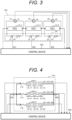
- FIG. 3 is a schematic block diagram illustrating a configuration of a battery module (basic battery unit) 100 applied to the present embodiment.
- the battery module 100 includes three battery cells 10-1, 10-2, 10-3 connected in series, three voltage sensors 16, and a balancing circuit 20.
- Each of the three battery cells 10-1 to 10-3 is equal to the battery cell 10 illustrated in FIG. 1 , and hereinafter, the battery cells 10-1 to 10-3 may be collectively referred to as the "battery cell 10".
- the three voltage sensors 16 output measurement results of cell voltages V1, V2, V3 (terminal voltages) of the battery cells 10-1 to 10-3.
- the balancing circuit 20 includes three switches 22 and three resistors 24 connected in series to these switches 22, respectively. Series circuits of the switches 22 and the resistors 24 are connected in parallel to the battery cells 10-1 to 10-3, respectively.
- the battery module 100 outputs the measurement results of the cell voltages V1 to V3 to a control device 500.
- FIG. 4 is a schematic block diagram illustrating a configuration of a battery pack 510 applied to the present embodiment.
- the battery pack 510 includes a positive electrode terminal 502, a negative electrode terminal 503, three battery modules 100-1,100-2,100-3, and three switches 110.
- Each of the battery modules 100-1 to 100-3 is equal to the battery module 100 illustrated in FIG. 3 . Therefore, the battery modules 100-1 to 100-3 may be collectively referred to as the "battery module 100".
- the battery pack 510 notifies the control device 500 of the measurement results of cell voltages V11, V12, V13, V21, V22, V23, V31, V32, V33 (terminal voltages) of these battery cells.
- the control device 500 controls the on/off states of the plurality of switches 110.
- the control device 500 can thus control the flow of the current according to the degree of deterioration in each module 100.
- the switch 110 is not an essential component, and can be omitted. That is, the battery modules 100-1 to 100-3 may be connected in parallel between the positive electrode terminal 502 and the negative electrode terminal 503. The cost can be reduced by omitting the switch 110, and the power loss due to the on-resistance of the switch 110 can also be reduced.
- the battery pack 510 includes the three battery modules 100-1 to 100-3, but the number of battery modules 100 included in the battery pack 510 is not particularly limited.
- the battery pack 510 may include only one module 100.
- the battery pack 510 may include a voltage sensor and a current sensor that measure the voltage and current of each of the battery modules 100-1 to 100-3, or may include a thermometer for measuring the internal temperature of the battery pack 510.
- the secondary battery system SY includes a battery pack 510 (secondary battery) and a control device 500 (secondary battery control device).
- the battery pack 510 is connected to the control device 500 via the positive electrode terminal 502 and the negative electrode terminal 503.
- the control part 570 outputs control signals to the switches 560,562,564, the variable resistor 553, and the power converter 554, based on the various input data.
- the control part 570 also outputs various image data to an external display 600. Note that the configuration of the control device 500 is not limited to that of FIG. 5 , and it is possible to adopt various circuit configurations capable of controlling the input current to the battery pack 510 based on the input signal from the battery pack 510.
- the computer 900 includes a CPU 901, a RAM 902, a ROM 903, an HDD 904, a communication interface (I/F) 905, an input-output I/F 906, and a media I/F 907.
- the communication I/F 905 is connected to an external communication circuit 915.
- the input-output I/F 906 is connected to the input-output device 916.
- the media I/F 907 reads and writes data from and in a recording medium 917.
- the ROM 903 stores a control program executed by the CPU, various data, and the like.
- the CPU 901 implements various functions by executing an application program read into the RAM 902.
- control part 570 includes a battery state acquisition part 400, a battery state determination part 401, a storage part 403, a battery state calculation part 404, a timer part 405, a normal operation control part 410 (first discharge control part), a capacity recovery control part 412 (second discharge control part), and an operation mode selection part 420.
- the battery state acquisition part 400 receives measurement signals from the battery pack 510, the ammeter 551, the voltmeter 552, and the like illustrated in FIG. 5 , and outputs measurement values such as the detected voltage value and current value to the battery state determination part 401.
- the timer part 405 acquires various types of time information such as a charging time and a discharging time of the battery pack 510.
- the calculation method for the battery SOC is not limited to the method shown here, and the battery SOC can be calculated using any method.
- the configuration of the control part 570 is not limited to that illustrated in FIG. 7 , but only needs to be a configuration that makes it possible to determine the state of the battery pack 510, apply a specific discharge current to the battery pack 510 for a specific time, and hold the battery in an open circuit state.
- the operation mode selection part 420 selects either the normal mode Mn or the capacity recovery mode Mr as the operation mode of the control device 500, based on a user operation.
- the operation mode selection part 420 can automatically select the operation mode, based on the determination result of the battery state determination part 401 regardless of a user operation. That is, when the battery state determination part 401 determines that "the capacity recovery control is necessary", the capacity recovery mode Mr can be selected, and in other cases, the normal mode Mn can be selected.
- the battery state determination part 401 may determine the necessity of the capacity recovery control, based on the use history of the battery pack 510, the SOC of the battery pack 510 at the present time, and the like.
- the normal operation control part 410 controls the discharge current of the battery pack 510 to prevent any of the cell voltages V11 to V33 from becoming a predetermined lower limit voltage V low .
- the switch 560 (cf. FIG. 5 ) is set to the OFF state, and the discharging of the battery pack 510 is forcibly terminated. Note that the lower limit voltage V low is stored in the storage part 403.
- the battery state calculation part 404 executes a step of determining the degree of deterioration for each battery cell 10 (a first step of evaluating the deterioration state) .
- the criterion for determining the degree of deterioration is not particularly limited, and for example, the battery pack 510 is brought into an open circuit state at a predetermined SOC, and the degree of deterioration can be determined based on the cell voltages V11 to V33 at that time.
- the battery state calculation part 404 obtains a positive electrode active material amount m p , a negative electrode active material amount m n , an index C p of the positional relationship of the discharge curve of the positive electrode, and an index C n of the positional relationship of the discharge curve of the negative electrode as the correction parameters, and stores these in the storage part 403.
- the battery state calculation part 404 multiplies the discharge amount of the positive electrode 12 (cf. FIG. 2 ) by the positive electrode active material amount m p , multiplies the discharge amount of the negative electrode 13 (cf. FIG. 2 ) by the positive electrode active material amount m p , and obtains calculated values of the positive electrode discharge curve and the negative electrode discharge curve, based on the reference mass of the positive electrode 12 and the reference mass of the negative electrode 13.
- FIG. 8 is a diagram illustrating an example of a charge-discharge curve obtained by calculation for a deterioration progression cell.
- the horizontal axis represents a discharge amount Q [Ah], the value "0" represents the fully charged state, and the negative value represents the overcharged state.
- the vertical axis on the left side of FIG. 8 represents the potential and the voltage.
- the vertical axis on the right side of FIG. 8 is a potential based on the lithium electrode.
- the potential based on the lithium electrode is expressed in units of "V vs. Li/Li + ".
- the positive electrode discharge curve calculation value Epc, the negative electrode discharge curve calculation value Enc, and the battery discharge curve calculation value Vc illustrated in FIG. 8 are examples obtained by such reproduction calculation processing.
- the illustrated example shows a state in which a capacity deviation has occurred between the positive electrode and the negative electrode, and the discharge end of the negative electrode discharge curve calculation value Enc and the discharge end of the battery discharge curve calculation value Vc coincide with each other.
- the capacity recovery control part 412 sets the energization electricity amount Qr in the capacity recovery control to satisfy: Qm ⁇ Qr ⁇ Q p0 ⁇ Q n0
- the battery cell 10-2 was a cell with the maximum degree of deterioration
- the battery cells 10-1, 10-3 were cells with a lesser degree of deterioration.
- the battery module 100 was discharged at a discharge rate of 1C until the cell voltage V2 of the battery cell 10-2 reached the lower limit voltage V low . That is, discharging of the individual battery cells 10 using the balancing circuit 20 was not performed.
- a state in which the cell voltage V2 has caused to reach the lower limit voltage V low in this manner is referred to as a "capacity recovery preparation state”.
- the "discharge rate of 1C" means a current density at which the battery capacity is discharged in one hour.
- the capacity recovery control was executed.
- a discharge pulse was applied to the battery module 100 in the capacity recovery preparation state at a discharge rate of 6 C for 10 seconds, and then the battery module 100 was held in an open circuit state for 15 minutes.
- the cell voltages V1, V2, V3 satisfy the voltage condition of Expression (1), that is, "V2 ⁇ V low ⁇ V1, V3".
- the capacity recovery rate is a percentage of the recovered capacity with respect to the initial capacity.
- the positive electrode utilization rate corresponds to the positive electrode active material amount m p described above, and is a value normalized by taking m p in its initial state as 100%. The decrease in the positive electrode utilization rate means that the positive electrode has deteriorated.
- the capacity recovery rate of the battery cell 10-2 was 2.2%.
- the amounts of change in the positive electrode utilization rates of the battery cells 10-1, 10-2, 10-3 were -0.8%, 0%, and -0.5%, respectively.
- the capacity recovery rate of the battery cell 10-2 was 2.8%, and a higher capacity recovery rate than in the first example was obtained.
- the positive electrode utilization rates of the battery cells 10-1, 10-3 are greatly reduced, accelerating the deterioration in the battery cells 10-1, 10-3 that have not deteriorated so much, which has been problematic.
- FIG. 10 is a diagram illustrating the capacity recovery rate and the amount of change in the positive electrode utilization rate of the deterioration progression cell in each of the second example and a comparative example.
- Comparative Example #1 in the drawing is the same as that illustrated in FIG. 9 . According to the present example, a higher capacity recovery rate than that of Comparative Example #1 can be realized, and a decrease in the positive electrode utilization rate is also reduced. As described above, according to the second embodiment, it is possible to realize a larger capacity recovery rate while further inhibiting a decrease in the positive electrode utilization rate.
- charging and discharging were repeated for the battery pack 510 illustrated in FIG. 4 , and the capacities of the battery modules 100-1, 100-2, 100-3 were reduced to 80%, 70%, and 80% of the initial capacity, respectively.
- the capacities of the battery modules 100-1, 100-2, 100-3 were reduced to 80%, 70%, and 80% of the initial capacity, respectively.
- the capacity of the battery cell 10-22 decreases to 70% with respect to the initial capacity, and the capacity of the other eight battery cells 10 holds 80% with respect to the initial capacity.
- the embodiment described above is a capacity recovery method for a secondary battery (510) including a plurality of battery cells 10, the capacity recovery method including: a first step of evaluating a deterioration state of each of the plurality of battery cells 10; and a second step of applying a discharge current to the secondary battery (510) such that a voltage of the battery cell 10 with greater deterioration among the plurality of battery cells 10 is lower than an end-of-discharge voltage (V low ) of the battery cell 10 in normal use, and a terminal voltage of each of the other batter cells 10 is equal to or higher than the end-of-discharge voltage (V low ).
Landscapes
- Engineering & Computer Science (AREA)
- Manufacturing & Machinery (AREA)
- Chemical & Material Sciences (AREA)
- Chemical Kinetics & Catalysis (AREA)
- Electrochemistry (AREA)
- General Chemical & Material Sciences (AREA)
- Power Engineering (AREA)
- Microelectronics & Electronic Packaging (AREA)
- Secondary Cells (AREA)
- Charge And Discharge Circuits For Batteries Or The Like (AREA)
Abstract
Description
- The present invention relates to a secondary battery control device, a secondary battery system, and a secondary battery capacity recovery method.
- As the background art of the present technical field, the abstract of
PTL 1 below describes as follows: "An ECU 960 controls a PCU 920 to execute capacity recovery control to recover the capacity of abattery pack 10. The capacity recovery control includes a discharge mode and a capacity recovery mode. In the discharge mode, the ECU 960 discharges thebattery pack 10 up to a predetermined over-discharging range. In the capacity recovery mode, the ECU 960 repeatedly executes, in the over-discharging range, voltage raising of the lithium ion secondary battery with discharging stopped and pulse discharging in which the lithium ion secondary battery is discharged while a discharging current is vibrated". - Further, paragraph 0080 of the specification of
PTL 2 below describes as follows: "As described above, according to the present invention, the situation of the charge-discharge curve of the entire positive electrode and the charge-discharge curve of the entire negative electrode inside the secondary battery can be seen in a non-destructive manner. This makes it possible to specify the cause of battery deterioration in a non-destructive manner, and determine the life with high accuracy. Furthermore, according to the present invention, by applying the result of the reproduction calculation, it is also possible to determine in a non-destructive manner an appropriate use range of the deteriorated battery with high accuracy, and acquire the amount of decrease in charge and discharge reactive species". The descriptions of these documents are included as part of the present specification. -
- PTL 1:
JP 2019-106333 A - PTL 2:
JP 4884404 B2 - Meanwhile, in the technology described above, there is a demand to recover the capacity of the secondary battery in a more appropriate manner.
- The present invention has been made in view of the above circumstances, and an object of the present invention is to provide a secondary battery control device, a secondary battery system, and a secondary battery capacity recovery method, which are capable of appropriately recovering the capacity of the secondary battery.
- In order to solve the above problems, a secondary battery control device according to the present invention is a secondary battery control device that includes: an operation mode selection part that selects one of a first operation mode and a second operation mode as an operation mode; a first discharge control part that stops discharging the secondary battery when the operation mode selection part selects the first operation mode, and upon a terminal voltage of one of the plurality of the battery cells falling below a first voltage; and a second discharge control part that applies a discharge current to the secondary battery when the operation mode selection part selects the second operation mode, such that a terminal voltage of one of the plurality of the battery cells satisfying a predetermined deterioration condition is lower than the first voltage, and a terminal voltage of each of the other battery cells is equal to or higher than the first voltage.
- According to the present invention, the capacity of the secondary battery can be appropriately recovered.
-
- [
FIG. 1] FIG. 1 is a schematic cross-sectional view of a bipolar battery cell. - [
FIG. 2] FIG. 2 is a schematic side view of an energy storage element. - [
FIG. 3] FIG. 3 is a schematic block diagram illustrating a configuration of a battery module. - [
FIG. 4] FIG. 4 is a schematic block diagram illustrating a configuration of a battery pack. - [
FIG. 5] FIG. 5 is a block diagram conceptually illustrating an example of a control device. - [
FIG. 6] FIG. 6 is a block diagram of a computer included in a control part. - [
FIG. 7] FIG. 7 is a block diagram illustrating functions of a control part. - [
FIG. 8] FIG. 8 is a diagram illustrating discharge characteristics of a battery cell. - [
FIG. 9] FIG. 9 is a diagram illustrating a capacity recovery rate and an amount of change in positive electrode utilization rate in each of a first example and comparative examples. - [
FIG. 10] FIG. 10 is a diagram illustrating a capacity recovery rate and an amount of change in positive electrode utilization rate in a second example and a comparative example. - [
FIG. 11] FIG. 11 is a diagram illustrating a capacity recovery rate and an amount of change in positive electrode utilization rate in a third example and a comparative example. - A lithium-ion battery is one of nonaqueous electrolyte secondary batteries, and due to its high energy density, the lithium-ion battery is also used as a battery of a portable device or a battery of an electric vehicle in recent years. However, it is known that a lithium-ion battery deteriorates with use, resulting in a decrease in battery capacity.
- In a lithium-ion battery, generally, a lithium metal oxide is used as an active material of a positive electrode, and a carbon material such as graphite is used as an active material of a negative electrode. The positive electrode and the negative electrode of the lithium-ion battery are formed by adding a binder, a conductive agent, and the like to a minute active material particle group to form a slurry, which is then applied to a metal foil.
- Inside the lithium-ion battery, lithium ions released from the active material of the positive electrode become occluded in the active material of the negative electrode during charging, and the lithium ions occluded in the active material of the negative electrode are released and become occluded in the active material of the positive electrode during discharging. As the lithium ions move between the electrodes as described above, a current flows between the electrodes of the external circuit.
- In such a lithium-ion battery, the capacity decreases due to:
- (1) electrical isolation of the positive electrode active material,
- (2) electrical isolation of the negative electrode active material; and
- (3) immobilization of lithium ions traveling between electrodes.
- The factor (3) above is caused by solidification of lithium ions as a film on the surface of the negative electrode or binding of lithium ions in the negative electrode due to the decomposition of the electrolyte. Of these, the capacity decrease due to the binding of lithium ions in the negative electrode can be recovered by electrochemical treatment. For example, by raising the potential of the negative electrode above a normal use range, lithium ions bound to the negative electrode are released, and the capacity is recovered. This corresponds to overdischarging the battery, and means lowering a state of charge (SOC) of the battery defined by the use voltage range of the battery below 0%.
- However, overdischarging the secondary battery that has not seriously deteriorated may accelerate the material deterioration of the positive and negative electrodes and the decomposition of the electrolyte, which may rather accelerate deterioration in the secondary battery. When a secondary battery pack includes one cell, overdischarge conditions can be set according to the deterioration state of the cell. However, when the secondary battery pack is configured by connecting a plurality of cells in series or in parallel, cells with different degrees of deterioration coexist, so that deterioration in a cell that has not seriously deteriorated may be accelerated depending on overdischarge conditions. Note that the cell is a minimum constituent unit of the secondary battery pack, and means a secondary battery including a positive electrode, a negative electrode, and an electrolyte.
- According to the technology to which the content of
PTL 1 described above is applied, it is considered that a capacity recovery method capable of effectively recovering the capacity of the lithium-ion secondary battery in a short time can be provided. That is, after the lithium-ion secondary battery is discharged to the overdischarge region, it is considered possible to repeatedly execute a voltage increase due to the stop of discharge, and pulse discharge for discharging the lithium-ion secondary battery while vibrating the discharge current. As a result, it is considered possible to realize a reduction in the time required for capacity recovery. - However, there is room for improvement in the method for recovering the capacity of the battery by pulse discharge in the overdischarge region as described above. For example, when a lithium-ion secondary battery pack includes a plurality of cells connected in series or in parallel, the uniform application (flow) of pulse discharge may accelerate deterioration in a cell with a degree of deterioration that is not serious.
- Therefore, an embodiment to be described later solves the problem described above by selectively recovering the capacity of a cell with greater deterioration in a secondary battery pack to which a plurality of cells are connected.
- First, a structure example of a bipolar battery cell applicable to the embodiment will be described with reference to
FIGS. 1 and 2 . -
FIG. 1 is a schematic cross-sectional view of abipolar battery cell 10. - In
FIG. 1 , thebattery cell 10 is a cell of a lithium-ion battery, and includes anenergy storage element 1, apositive electrode terminal 2, anegative electrode terminal 3, and anexterior material 6. Aseparator 5 is included in theenergy storage element 1. Theexterior material 6 is configured using a laminate film or a material similar thereto. Note that the shape of thebattery cell 10 is not limited to a square shape as illustrated inFIG. 1 , but may be a cylindrical shape although not illustrated. -
FIG. 2 is a schematic side view of theenergy storage element 1. - As illustrated in
FIG. 2 , in theenergy storage element 1, a plurality ofpositive electrodes 12 and a plurality ofnegative electrodes 13 are alternately stacked with theseparator 5 interposed therebetween. Theenergy storage element 1 illustrated inFIG. 1 corresponds to a region where thepositive electrode 12 and thenegative electrode 13 are seen to overlay each other. Note that the structure of theenergy storage element 1 is not limited to the stacked type as illustrated inFIG. 2 . That is, although not illustrated in the drawing, thepositive electrode 12 and thenegative electrode 13 may be stacked to face each other with theseparator 5 interposed therebetween, and then wound to produce a wound type. Theenergy storage element 1 further includes an electrolyte (not illustrated), and the electrolyte is impregnated into the micropores of thepositive electrode 12, thenegative electrode 13, theseparator 5 and the like. As theseparator 5, for example, polypropylene can be applied. However, in addition to polypropylene, a microporous film made of polyolefin such as polyethylene, a nonwoven fabric, and the like can also be applied as theseparator 5. - The
positive electrode 12 and thenegative electrode 13 are each prepared by applying a mixture of an appropriate electrode active material, a conductive agent, a binder, and the like to an appropriate metal current collecting foil. A metal tab is connected to each of the current collecting foils of thepositive electrode 12 and thenegative electrode 13. Theexterior material 6 is sealed such that only the tab portion is exposed to the outside of theexterior material 6. This makes the tabs thepositive electrode terminal 2 and thenegative electrode terminal 3 inFIG. 1 . Hereinafter, the potentials of thepositive electrode 12 and thenegative electrode 13 are referred to as a positive electrode potential Ep and a negative electrode potential En. A difference therebetween, that is, "Ep - En" is a voltage between thepositive electrode terminal 2 and thenegative electrode terminal 3, and this is referred to as a cell voltage V. - As the current collecting foil of the
positive electrode 12, an aluminum foil having a thickness of 10 to 100 um, a perforated aluminum foil having a thickness of 10 to 100 um and a hole diameter of 0.1 to 10 mm, an expanded metal, a foamed metal plate, or the like is used. In addition to aluminum, stainless steel, titanium, and the like can also be applied as the material of the current collecting foil. In the present embodiment, any current collector can be used without being limited by a material, a shape, a manufacturing method, and the like. - The electrode active material of the
positive electrode 12 desirably contains reactive species therein. The reactive species of the lithium-ion battery are lithium ions. In this case, the electrode active material of thepositive electrode 12 contains a lithium-containing compound capable of reversibly inserting and desorbing lithium ions. The type of the electrode active material of thepositive electrode 12 is not particularly limited, and examples thereof include lithium transition metal phosphates such as lithium cobaltate, manganese-substituted lithium cobaltate, lithium manganate, lithium nickelate, and olivine type lithium iron phosphate, and LiwNixCoyMnzO2 (where w, x, y, and z are 0 or positive values.). As the electrode active material of thepositive electrode 12, one kind alone or two or more kinds of the above materials may be contained. - As the current collecting foil of the
negative electrode 13, a copper foil having a thickness of 10 to 100 um, a perforated copper foil having a thickness of 10 to 100 µm and a hole diameter of 0.1 to 10 mm, an expanded metal, a foamed metal plate, or the like is used. In addition to copper, stainless steel, titanium, and the like can also be applied as the material of the current collecting foil. In the present embodiment, any current collector can be used without being limited by a material, a shape, a manufacturing method, and the like. - The electrode active material of the
negative electrode 13 contains a material capable of reversibly inserting and desorbing lithium ions. The type of the electrode active material of thenegative electrode 13 is not particularly limited, and it is possible to apply, for example, natural graphite, a composite carbonaceous material obtained by forming a film on natural graphite by a dry chemical vapor deposition (CVD) method or a wet spraying method, artificial graphite produced by firing using a resin material such as epoxy or phenol or a pitch-based material obtained from petroleum or coal as a raw material, silicon (Si), graphite obtained by mixing silicon, a non-graphitizable carbon material, lithium titanate Li4Ti5O12, niobium titanium-based oxide TiNb2O7, and the like. The negative electrode active material may contain one kind alone or two or more kinds of the above materials. - The
energy storage element 1 is impregnated with an electrolyte. The electrolyte is not particularly limited, and in the case of a lithium-ion battery, it is possible to apply, for example, an aprotic organic solvent such as ethylene carbonate (EC), propylene carbonate (PC), butylene carbonate (BC), dimethyl carbonate (DMC), ethyl methyl carbonate (EMC), diethyl carbonate (DEC), methyl propyl carbonate (MPC), or ethyl propyl carbonate (EPC). - The electrolyte may be obtained by dissolving, in a mixed solvent of two or more of these organic compounds, a lithium salt such as lithium hexafluorophosphate, lithium tetrafluoroborate, lithium perchlorate, lithium iodide, lithium chloride, lithium bromide, LiB[OCOCF3]4, LiB [OCOCF2CF3]4, LiPF4(CF3)2, LiN(SO2CF3)2, LiN(SO2CF2CF3)2, or a mixed lithium salt of two or more of these.
- A solid electrolyte may be used instead of the electrolyte. The solid electrolyte is not particularly limited, and examples thereof include ion conductive polymers such as polyethylene oxide, polyacrylonitrile, polyvinylidene fluoride, polymethyl methacrylate, polyhexafluoropropylene, and polyethylene oxide. When these solid polymer electrolytes are used, the
separator 5 can be omitted. -
FIG. 3 is a schematic block diagram illustrating a configuration of a battery module (basic battery unit) 100 applied to the present embodiment. - In
FIG. 3 , thebattery module 100 includes three battery cells 10-1, 10-2, 10-3 connected in series, threevoltage sensors 16, and abalancing circuit 20. Each of the three battery cells 10-1 to 10-3 is equal to thebattery cell 10 illustrated inFIG. 1 , and hereinafter, the battery cells 10-1 to 10-3 may be collectively referred to as the "battery cell 10". The threevoltage sensors 16 output measurement results of cell voltages V1, V2, V3 (terminal voltages) of the battery cells 10-1 to 10-3. - The balancing
circuit 20 includes threeswitches 22 and threeresistors 24 connected in series to theseswitches 22, respectively. Series circuits of theswitches 22 and theresistors 24 are connected in parallel to the battery cells 10-1 to 10-3, respectively. Thebattery module 100 outputs the measurement results of the cell voltages V1 to V3 to acontrol device 500. - The on/off states of the
respective switches 22 are controlled based on control signals SD1, SD2, SD3 supplied from thecontrol device 500. Based on the measurement results of the cell voltages V1 to V3, thecontrol device 500 outputs the control signals SD1, SD2, SD3 to reduce the difference among the cell voltages V1 to V3, thereby discharging thebattery cell 10 having a high voltage. - In the following description, a "battery cell" may be simply referred to as a "cell", and a "battery module" may be simply referred to as a "module". In the example illustrated in
FIG. 3 , onebattery module 100 includes threebattery cells 10, but the number ofbattery cells 10 included in onebattery module 100 may be any number equal to or more than one. - In the example illustrated in
FIG. 3 , for simplicity of description, a passive type including theswitch 22 and theresistor 24 is shown as the balancingcircuit 20. However, the balancingcircuit 20 may adopt an active type balancing circuit (not illustrated). That is, a balancing circuit that charges a cell having a low cell voltage by a charge of a cell having a high cell voltage may be adopted. -
FIG. 4 is a schematic block diagram illustrating a configuration of abattery pack 510 applied to the present embodiment. - In
FIG. 4 , thebattery pack 510 includes apositive electrode terminal 502, anegative electrode terminal 503, three battery modules 100-1,100-2,100-3, and threeswitches 110. Each of the battery modules 100-1 to 100-3 is equal to thebattery module 100 illustrated inFIG. 3 . Therefore, the battery modules 100-1 to 100-3 may be collectively referred to as the "battery module 100". - An on/off state of each
switch 110 is set based on a command supplied from thecontrol device 500. When all theswitches 110 are turned on, the battery modules 100-1 to 100-3 are connected in parallel between thepositive electrode terminal 502 and thenegative electrode terminal 503 of thebattery pack 510. Thebattery cells 10, three of which are included in each of the three battery modules 100-1 to 100-3, are referred to as battery cells 10-11, 10-12, 10-13, 10-21, 10-22, 10-23, 10-31, 10-32, 10-33. - The
battery pack 510 notifies thecontrol device 500 of the measurement results of cell voltages V11, V12, V13, V21, V22, V23, V31, V32, V33 (terminal voltages) of these battery cells. As described above, thecontrol device 500 controls the on/off states of the plurality ofswitches 110. Thecontrol device 500 can thus control the flow of the current according to the degree of deterioration in eachmodule 100. - However, the
switch 110 is not an essential component, and can be omitted. That is, the battery modules 100-1 to 100-3 may be connected in parallel between thepositive electrode terminal 502 and thenegative electrode terminal 503. The cost can be reduced by omitting theswitch 110, and the power loss due to the on-resistance of theswitch 110 can also be reduced. In the illustrated example, thebattery pack 510 includes the three battery modules 100-1 to 100-3, but the number ofbattery modules 100 included in thebattery pack 510 is not particularly limited. For example, thebattery pack 510 may include only onemodule 100. Thebattery pack 510 may include a voltage sensor and a current sensor that measure the voltage and current of each of the battery modules 100-1 to 100-3, or may include a thermometer for measuring the internal temperature of thebattery pack 510. -
FIG. 5 is a block diagram illustrating a configuration of a secondary battery system SY according to a first embodiment. - In
FIG. 5 , the secondary battery system SY includes a battery pack 510 (secondary battery) and a control device 500 (secondary battery control device). Thebattery pack 510 is connected to thecontrol device 500 via thepositive electrode terminal 502 and thenegative electrode terminal 503. - The
control device 500 includes anammeter 551, avoltmeter 552, avariable resistor 553, apower converter 554, switches 560,562,564, and acontrol part 570. Thepower converter 554 converts DC power discharged from thebattery pack 510 into AC power and supplies the AC power to apower system 610. Thepower converter 554 converts the AC power supplied from thepower system 610 into DC power to charge thebattery pack 510. The measurement results of the cell voltages V11 to V33 (cf.FIG. 4 ) in thebattery pack 510 are supplied to thecontrol part 570. Furthermore, the measurement results of theammeter 551 and thevoltmeter 552 are also supplied to thecontrol part 570. These measurement results are the current value of the charge-discharge current flowing through thebattery pack 510 and a battery voltage Ev. - The
control part 570 outputs control signals to the switches 560,562,564, thevariable resistor 553, and thepower converter 554, based on the various input data. Thecontrol part 570 also outputs various image data to anexternal display 600. Note that the configuration of thecontrol device 500 is not limited to that ofFIG. 5 , and it is possible to adopt various circuit configurations capable of controlling the input current to thebattery pack 510 based on the input signal from thebattery pack 510. -
FIG. 6 is a block diagram of acomputer 900 included in thecontrol part 570. - In
FIG. 6 , thecomputer 900 includes aCPU 901, aRAM 902, aROM 903, anHDD 904, a communication interface (I/F) 905, an input-output I/F 906, and a media I/F 907. The communication I/F 905 is connected to anexternal communication circuit 915. The input-output I/F 906 is connected to the input-output device 916. The media I/F 907 reads and writes data from and in arecording medium 917. TheROM 903 stores a control program executed by the CPU, various data, and the like. TheCPU 901 implements various functions by executing an application program read into theRAM 902. -
FIG. 7 is a block diagram illustrating functions of thecontrol part 570, and each block in the drawing indicates a function implemented using the application program or the like. - That is, the
control part 570 includes a batterystate acquisition part 400, a batterystate determination part 401, astorage part 403, a batterystate calculation part 404, atimer part 405, a normal operation control part 410 (first discharge control part), a capacity recovery control part 412 (second discharge control part), and an operationmode selection part 420. - The operation
mode selection part 420 selects either a normal mode Mn (first operation mode) or a capacity recovery mode Mr (second operation mode) as the operation mode of thecontrol device 500. The operation mode may be selected by a manual operation of a user, or may be selected according to the state of thebattery pack 510. The normal mode Mn is an operation mode in which normal charging and discharging are performed for thebattery pack 510. On the other hand, the capacity recovery mode Mr is an operation mode in which the capacity recovery control is performed for some or all of the battery cells 10-11 to 10-33 (cf.FIG. 4 ) . - The battery
state acquisition part 400 receives measurement signals from thebattery pack 510, theammeter 551, thevoltmeter 552, and the like illustrated inFIG. 5 , and outputs measurement values such as the detected voltage value and current value to the batterystate determination part 401. Thetimer part 405 acquires various types of time information such as a charging time and a discharging time of thebattery pack 510. - The
storage part 403 stores various types of information, and supplies the stored information to the batterystate determination part 401, the batterystate calculation part 404, and the like as necessary. The stored information includes the following. - · A correspondence table between the cell voltage V and the SOC (or the amount of electricity) of the
battery cell 10 - · The initial capacity of the
battery cell 10 - · Information input from the battery
state determination part 401. - The battery
state determination part 401 acquires various states of thebattery pack 510 based on various measurement values input from the batterystate acquisition part 400 and time information supplied from thetimer part 405. The acquired states include the amount of electricity of eachbattery cell 10 in thebattery pack 510. The batterystate determination part 401 stores the battery voltage Ev and the cell voltages V11 to V33 in thestorage part 403 in association with the current time. Thereby, thestorage part 403 stores time-series information of the battery voltage Ev and the cell voltages V11 to V33. - The battery
state determination part 401 compares various determination values input from the batterystate calculation part 404 with various control values input from thestorage part 403. Then, the batterystate determination part 401 determines the state of thebattery pack 510, and outputs the result to the normaloperation control part 410 and the capacityrecovery control part 412. - The battery
state calculation part 404 appropriately corrects the acquired measurement value and initial value, calculates a physical quantity for determining the battery state, and outputs the physical quantity to the batterystate determination part 401. Specifically, the battery SOC is calculated from the correspondence table between the battery voltage and the battery SOC stored in thestorage part 403 and the battery voltage input from the batterystate determination part 401, and is output to the batterystate determination part 401. In addition, the current value and the application time of the discharge pulse are calculated from the battery voltage and the initial capacity of the battery stored in thestorage part 403, and are output to the batterystate determination part 401. - Note that the calculation method for the battery SOC is not limited to the method shown here, and the battery SOC can be calculated using any method.
- The configuration of the
control part 570 is not limited to that illustrated inFIG. 7 , but only needs to be a configuration that makes it possible to determine the state of thebattery pack 510, apply a specific discharge current to thebattery pack 510 for a specific time, and hold the battery in an open circuit state. - In
FIG. 7 , the operationmode selection part 420 selects either the normal mode Mn or the capacity recovery mode Mr as the operation mode of thecontrol device 500, based on a user operation. In addition, the operationmode selection part 420 can automatically select the operation mode, based on the determination result of the batterystate determination part 401 regardless of a user operation. That is, when the batterystate determination part 401 determines that "the capacity recovery control is necessary", the capacity recovery mode Mr can be selected, and in other cases, the normal mode Mn can be selected. The batterystate determination part 401 may determine the necessity of the capacity recovery control, based on the use history of thebattery pack 510, the SOC of thebattery pack 510 at the present time, and the like. - When the normal mode Mn is selected as the operation mode, the normal
operation control part 410 inputs and outputs power between thebattery pack 510 and the power system 610 (cf.FIG. 5 ) via thepower converter 554. That is, in the case of discharging thebattery pack 510, the normaloperation control part 410 causes thepower converter 554 to convert the discharged DC power into AC power and supply the AC power to thepower system 610. In the case of charging thebattery pack 510, the normaloperation control part 410 causes thepower converter 554 to convert the AC power supplied from thepower system 610 into DC power and supply the DC power to thebattery pack 510. - In the normal mode Mn, the normal
operation control part 410 controls the discharge current of thebattery pack 510 to prevent any of the cell voltages V11 to V33 from becoming a predetermined lower limit voltage Vlow. When any of the cell voltages V11 to V33 falls below the lower limit voltage Vlow, the switch 560 (cf.FIG. 5 ) is set to the OFF state, and the discharging of thebattery pack 510 is forcibly terminated. Note that the lower limit voltage Vlow is stored in thestorage part 403. - In the capacity recovery mode Mr, the capacity
recovery control part 412 executes the capacity recovery control. During the progress of the capacity recovery control, it is recommended that the user be alerted by indicating on thedisplay 600 that the capacity recovery control is being executed. The content of the capacity recovery control is not particularly limited but may include, for example, applying a high-current discharge pulse to thebattery pack 510 and then pausing the operation of thebattery pack 510 for a certain time. - That is, the capacity
recovery control part 412 recovers the cell capacity decreased due to the instantaneous drop of the cell voltage V (cf.FIG. 1 ) and the subsequent relaxation. At this time, a greater recovery effect can be obtained by lowering the cell voltage V below the lower limit voltage Vlow described above. Therefore, in order to prevent the battery system from being urgently stopped due to the cell voltage V falling below Vlow, the lower limit voltage of the cell is set to be lower than Vlow in the capacity recovery control. The application and pause of the discharge pulse may be performed once or repeatedly. - As illustrated in
FIGS. 3 and 4 , when thebattery pack 510 includes thebattery module 100 in which the plurality ofbattery cells 10 are connected in series, the discharge current is uniformly applied to eachbattery cell 10 in thebattery module 100. Thus, when a high-current discharge pulse is applied to thebattery pack 510 by the capacity recovery control, the cell voltage V is lowered also for thebattery cell 10 having a small decrease in capacity, that is, thebattery cell 10 with a lesser degree of deterioration. This may rather accelerate deterioration in thebattery cell 10 with a lesser degree of deterioration. - In order to avoid such a situation, the capacity
recovery control part 412 of the present embodiment controls the current value of the discharge pulse so that the cell voltage V of thebattery cell 10 with a greater degree of deterioration is lower than the lower limit voltage Vlow and the cell voltage V of thebattery cell 10 with a lesser degree of deterioration is equal to or higher than the lower limit voltage Vlow. In other words, the capacityrecovery control part 412 executes a step of applying a discharge current to the secondary battery (510) such that the voltage of thebattery cell 10 with greater deterioration among the plurality ofbattery cells 10 is less than the end-of-discharge voltage (Vlow) of thebattery cell 10 in normal use, and the terminal voltage of each of theother battery cells 10 is equal to or higher than the end-of-discharge voltage (Vlow) (second step). In general, thebattery cell 10 with greater deterioration has a smaller discharge capacity and a larger internal resistance than theother battery cells 10, resulting in a larger voltage drop even when the same discharge current value is applied. - Therefore, when the cell voltage V of the
battery cell 10 with a greater degree of deterioration is Vx and the cell voltage V of thebattery cell 10 with a lesser degree of deterioration is Vy, there is a combination of a discharge current value and a discharging time satisfying Expression (1) below.
- The capacity
recovery control part 412 of the present embodiment controls the current value and the application time of the pulse discharge to satisfy the condition of Expression (1). - The battery
state calculation part 404 executes a step of determining the degree of deterioration for each battery cell 10 (a first step of evaluating the deterioration state) . Here, the criterion for determining the degree of deterioration is not particularly limited, and for example, thebattery pack 510 is brought into an open circuit state at a predetermined SOC, and the degree of deterioration can be determined based on the cell voltages V11 to V33 at that time. That is, when the measured cell voltages V11 to V33 are equal to or less than a predetermined value Vdg (not illustrated), it can be determined that "the degree of deterioration is greater" (in other words, "the predetermined deterioration condition" is satisfied), and otherwise, it can be determined that "the degree of deterioration is less". The predetermined value Vdg may be determined in advance and stored in thestorage part 403, or may be calculated by the batterystate calculation part 404 based on each of the cell voltages V11 to V33. In the following description, the "battery cell 10 with a greater degree of deterioration" may be referred to as a "deterioration progression cell". - As illustrated in
FIG. 4 , thebattery module 100 such as a lithium-ion secondary battery generally includes the balancingcircuit 20. - This enables the capacity
recovery control part 412 of the present embodiment to perform partial discharge control only on somebattery cells 10 by using thebalancing circuit 20 before uniformly applying a discharge current to eachbattery cell 10 included in thebattery module 100. As a result, the voltage condition shown in Expression (1) can be extended. - That is, when a user instruction to "execute partial discharge control" is input to the
control part 570, the capacityrecovery control part 412 closes theswitch 22 for the deterioration progression cell before applying the discharge pulse, to select and discharge only the deterioration progression cell, thereby lowering its SOC. After the partial discharge control ends, the capacityrecovery control part 412 opens theswitch 22 and uniformly applies a discharge current to eachbattery cell 10 of thebattery module 100. - By executing this partial discharge control, the cell voltage V of the deterioration progression cell can be lowered to a greater extent than the other cell voltages V in advance, thus satisfying the voltage condition of Expression (1) under a wide range of discharge pulse conditions. Note that the partial discharge control is not limited to the passive
type balancing circuit 20 illustrated inFIG. 3 , but can be similarly realized in an active type balancing circuit (not illustrated). - As illustrated in
FIG. 4 , in the case of thebattery pack 510 in which the plurality ofbattery modules 100 can be connected in parallel, even when a high-current discharge pulse is applied to thebattery pack 510, a large current is not always applied to the deterioration progression cell. Therefore, when the user gives a predetermined instruction, the capacityrecovery control part 412 classifies themodule 100 into a module including the deterioration progression cell and a module not including the deterioration progression cell. Then, the capacityrecovery control part 412 turns on theswitch 110 only for themodule 100 including the deterioration progression cell, and turns off theswitch 110 for theother modules 100. As a result, only themodule 100 including the deterioration progression cell can be selected, and the discharge pulse can be applied. - The capacity
recovery control part 412 can limit the discharge current value and the application time of the discharge pulse according to not only the voltage condition of Expression (1) described above but also other conditions. - For example, even in the deterioration progression cell, repeatedly applying the discharge pulse may cause the positive electrode to become overdischarged and accelerate deterioration in the positive electrode. In order to prevent this, it is preferable to control the amount of electricity applied by the discharge pulse so that the positive electrode is not overdischarged. This is realized by the following method.
- First, for the prototype of the
battery cell 10, the charge-discharge curves of the cell voltage V, the positive electrode potential Ep, and the negative electrode potential En (cf.FIG. 1 ), that is, the characteristics of V, Ep, and En for various discharge amounts are acquired. To directly measure the positive electrode potential Ep and the negative electrode potential En, it is necessary to destroy thebattery cell 10, and hence thebattery cell 10 of the same type as that applied to thebattery pack 510 is used as a prototype to acquire its charge-discharge curve. - The battery
state determination part 401 stores the relationship between the cell voltage V and the current value for the deterioration progression cell in thestorage part 403. Integrating the current value yields the charge-discharge amount, and using this, the batterystate calculation part 404 calculates data for the charge-discharge curve of the cell voltage V of each deterioration progression cell. The voltage of the charge-discharge curve is desirably a value close to the open circuit voltage. The energization method in the calculation of the data for the charge-discharge curve is optional. - For example, there is a method of discharging the deterioration progression cell from a fully charged state to a fully discharged state at a small, constant current, or a method of charging the cell from the fully discharged state to the fully charged state at a small, constant current. A method that may also be used is to repeat a cycle of discharging the deterioration progression cell at a constant current for a certain time and then pausing for a certain time from the fully charged state to the fully discharged state. In addition, a method that may also be used is to repeat a cycle of charging the deterioration progression cell at a constant current for a certain time and then pausing for a certain time from a fully discharged state to a fully charged state. By such a method, data on the relationship between the charge-discharge amount and the open circuit voltage can be acquired.
- There is also a method of acquiring the current waveform and the voltage waveform of the deterioration progression cell during operation in the normal mode Mn, statistically processing these waveforms, or performing regression calculation processing (reproduction calculation processing) based on an equivalent circuit to estimate an open circuit voltage, and estimating the relationship between the charge-discharge amount and the open circuit voltage. With respect to the energization method in the calculation of the data for the charge-discharge curve described above, "discharging from the fully charged state to the fully discharged state" and "charging from the fully discharged state to the fully charged state" have been described, but the energization method is not necessarily limited to discharging or charging within these ranges. The charge-discharge range is desirably wide, and it is most desirable to perform charging and discharging within a range of 100%. However, as long as the subsequent step can be smoothly performed, charging and discharging may be performed within a range of 50% or more from the fully charged state to the fully discharged state. Furthermore, if possible, the charge-discharge range may be in the range of less than 50%.
- Next, the battery
state calculation part 404 constructs the charge-discharge curves of the positive electrode potential Ep and the negative electrode potential En of the deterioration progression cell by regression calculation processing (reproduction calculation processing), based on the charge-discharge curve of the prototype stored in advance in thestorage part 403 and the charge-discharge curve of the cell voltage V of the deterioration progression cell. - The content of the regression calculation processing (reproduction calculation processing) is described in
PTL 2 mentioned above, and the outline thereof will be described below. - First, the battery
state calculation part 404 obtains a positive electrode active material amount mp, a negative electrode active material amount mn, an index Cp of the positional relationship of the discharge curve of the positive electrode, and an index Cn of the positional relationship of the discharge curve of the negative electrode as the correction parameters, and stores these in thestorage part 403. Next, the batterystate calculation part 404 multiplies the discharge amount of the positive electrode 12 (cf.FIG. 2 ) by the positive electrode active material amount mp, multiplies the discharge amount of the negative electrode 13 (cf.FIG. 2 ) by the positive electrode active material amount mp, and obtains calculated values of the positive electrode discharge curve and the negative electrode discharge curve, based on the reference mass of thepositive electrode 12 and the reference mass of thenegative electrode 13. -
FIG. 8 is a diagram illustrating an example of a charge-discharge curve obtained by calculation for a deterioration progression cell. - In
FIG. 8 , the horizontal axis represents a discharge amount Q [Ah], the value "0" represents the fully charged state, and the negative value represents the overcharged state. The vertical axis on the left side ofFIG. 8 represents the potential and the voltage. The vertical axis on the right side ofFIG. 8 is a potential based on the lithium electrode. Hereinafter, the potential based on the lithium electrode is expressed in units of "V vs. Li/Li+". - The calculated values of the positive electrode potential Ep and the negative electrode potential En (cf.
FIG. 1 ) are referred to as a positive electrode discharge curve calculation value Epc (positive electrode potential curve) and a negative electrode discharge curve calculation value Enc (negative electrode potential curve). The difference (Epc - Enc) between these is referred to as a battery discharge curve calculation value Vc. The batterystate calculation part 404 adjusts mp, mn, Cp, and Cn, which are correction parameters, so that the battery discharge curve calculation value Vc approaches (desirably matches) the charge-discharge curve of the actually measured cell voltage V. Then, the positive electrode discharge curve calculation value Epc and the negative electrode discharge curve calculation value Enc are recalculated and updated based on the adjusted correction parameters mp, mn, Cp, Cn. - The positive electrode discharge curve calculation value Epc, the negative electrode discharge curve calculation value Enc, and the battery discharge curve calculation value Vc illustrated in
FIG. 8 are examples obtained by such reproduction calculation processing. The illustrated example shows a state in which a capacity deviation has occurred between the positive electrode and the negative electrode, and the discharge end of the negative electrode discharge curve calculation value Enc and the discharge end of the battery discharge curve calculation value Vc coincide with each other. - Next, the battery
state calculation part 404 calculates the charge-discharge capacity of the deterioration progression cell in a predetermined charged state based on the positive electrode discharge curve calculation value Epc and the negative electrode discharge curve calculation value Enc. More specifically, a discharge amount Qp0 (first discharge amount) corresponding to a predetermined positive electrode potential Vp0 (first potential), a discharge amount Qn0 (second discharge amount) corresponding to a predetermined negative electrode potential Vn0 (second potential), and a difference (Qp0 - Qn0) between both are calculated. - Here, the negative electrode potential Vn0 is a potential at the discharge end of the negative electrode discharge curve calculation value Enc, and may be set at a position where the negative electrode potential rapidly rises. In the illustrated example, the negative electrode potential Vn0 is set to 0.4 [V vs. Li/Li+]. The positive electrode potential Vp0 is a potential slightly higher than the discharge end of the positive electrode discharge curve calculation value Epc, and may be set to a potential before the positive electrode potential rapidly decreases. In the illustrated example, the positive electrode potential Vp0 is set to "0.6 V vs. Li/Li+".
- Here, when the energization electricity amount of the pulse discharge exceeds (Qp0 - Qn0) in the deterioration progression cell, the positive electrode is discharged to the overdischarge region, which may accelerate the deterioration in the positive electrode.
- Therefore, when the remaining capacity of the
battery cell 10 with the greatest deterioration is Qm and the energization electricity amount due to the pulse discharge is Qr, the capacityrecovery control part 412 sets the energization electricity amount Qr in the capacity recovery control to satisfy:
- This makes it possible to inhibit material deterioration of the positive electrode.
- Hereinafter, various examples and comparative examples of the present embodiment will be described, and first, a first example will be described.
- In the present example, charging and discharging were repeated for the
battery module 100 illustrated inFIG. 3 , and the capacities of the battery cells 10-1, 10-2, 10-3 were reduced to 80%, 70%, and 80%, respectively, with respect to the initial capacity. That is, the battery cell 10-2 was a cell with the maximum degree of deterioration, and the battery cells 10-1, 10-3 were cells with a lesser degree of deterioration. - In the present example, before the capacity recovery control, the
battery module 100 was discharged at a discharge rate of 1C until the cell voltage V2 of the battery cell 10-2 reached the lower limit voltage Vlow. That is, discharging of theindividual battery cells 10 using thebalancing circuit 20 was not performed. A state in which the cell voltage V2 has caused to reach the lower limit voltage Vlow in this manner is referred to as a "capacity recovery preparation state". Note that the "discharge rate of 1C" means a current density at which the battery capacity is discharged in one hour. - After the capacity recovery preparation state described above was established, the capacity recovery control was executed. In the capacity recovery control of the present example, a discharge pulse was applied to the
battery module 100 in the capacity recovery preparation state at a discharge rate of 6 C for 10 seconds, and then thebattery module 100 was held in an open circuit state for 15 minutes. By this capacity recovery control, the cell voltages V1, V2, V3 satisfy the voltage condition of Expression (1), that is, "V2 < Vlow < V1, V3". -
FIG. 9 is a diagram illustrating the capacity recovery rate and the amount of change in the positive electrode utilization rate of the deterioration progression cell in each of the first example and comparative examples. - Here, the capacity recovery rate is a percentage of the recovered capacity with respect to the initial capacity. The positive electrode utilization rate corresponds to the positive electrode active material amount mp described above, and is a value normalized by taking mp in its initial state as 100%. The decrease in the positive electrode utilization rate means that the positive electrode has deteriorated.
- As illustrated in the drawing, in the first example, the capacity recovery rate of the battery cell 10-2 was 2.2%. The amounts of change in the positive electrode utilization rates of the battery cells 10-1, 10-2, 10-3 were -0.8%, 0%, and -0.5%, respectively.
- Next,
Comparative Example # 1 andComparative Example # 2 will be described. -
Comparative Example # 1 is an example in which a discharge pulse was applied at a discharge rate of 15 C for 4 seconds in the capacity recovery preparation state described above, and then held in the open circuit state for 15 minutes. InComparative Example # 1, "V1, V2, V3 < Vlow" is satisfied, and the relationship of Expression (1) described above does not hold. - As illustrated in
FIG. 9 , inComparative Example # 1, the capacity recovery rate of the battery cell 10-2 was 2.8%, and a higher capacity recovery rate than in the first example was obtained. However, particularly, the positive electrode utilization rates of the battery cells 10-1, 10-3 are greatly reduced, accelerating the deterioration in the battery cells 10-1, 10-3 that have not deteriorated so much, which has been problematic. - Next,
Comparative Example # 2 is an example in which a discharge pulse was applied at a discharge rate of 0.5 C for 120 seconds in the capacity recovery preparation state described above, and then held in the open circuit state for 15 minutes. InComparative Example # 2, "Vlow < V1, V2, V3" is satisfied, and the relationship of Expression (1) described above does not hold. - As illustrated in the drawing, in
Comparative Example # 2, the capacity recovery rate of the battery cell 10-2 was 0.4%, and the capacity recovery rate was lower than that of the first example. - As described above, according to the first example, it is possible to effectively recover the capacity of the battery cell 10-2 while inhibiting the decrease in the positive electrode utilization rate.
- Next, a second embodiment will be described.
- Also, in the present example, similarly to the first example, charging and discharging were repeated for the
battery module 100 illustrated inFIG. 3 , and the capacities of the battery cells 10-1, 10-2, 10-3 were reduced to 80%, 70%, and 80%, respectively, with respect to the initial capacity. - Next, partial discharge control was performed on the battery cell 10-2 as a deterioration progression cell using the
balancing circuit 20. That is, theswitch 22 corresponding to the battery cell 10-2 was closed, and the battery cell 10-2 was discharged to the lower limit voltage Vlow. - Next, as the capacity recovery control, a discharge pulse was applied to the
battery module 100 at a discharge rate of 15 C for 4 seconds, and then thebattery module 100 was held in the open circuit state for 15 minutes. In the present example, since the capacity recovery control is performed after only the battery cell 10-2 is discharged, the voltage condition of Expression (1), that is, "V2 < Vlow < V1, V3", is also satisfied in this case. -
FIG. 10 is a diagram illustrating the capacity recovery rate and the amount of change in the positive electrode utilization rate of the deterioration progression cell in each of the second example and a comparative example. -
Comparative Example # 1 in the drawing is the same as that illustrated inFIG. 9 . According to the present example, a higher capacity recovery rate than that ofComparative Example # 1 can be realized, and a decrease in the positive electrode utilization rate is also reduced. As described above, according to the second embodiment, it is possible to realize a larger capacity recovery rate while further inhibiting a decrease in the positive electrode utilization rate. - Next, a third example will be described.
- In the present example, charging and discharging were repeated for the
battery pack 510 illustrated inFIG. 4 , and the capacities of the battery modules 100-1, 100-2, 100-3 were reduced to 80%, 70%, and 80% of the initial capacity, respectively. Among the nine battery cells 10-11 to 10-33 inFIG. 4 , only the capacity of the battery cell 10-22 decreases to 70% with respect to the initial capacity, and the capacity of the other eightbattery cells 10 holds 80% with respect to the initial capacity. - In the present example, partial discharge control was performed in which the switch 22 (cf.
FIG. 3 ) for the battery cell 10-22 was closed to discharge only the battery cell 10-22 to the lower limit voltage Vlow. When the partial discharge control was completed, theswitch 110 was completely closed, a discharge pulse was applied at a discharge rate of 15 C for 4 seconds as the capacity recovery control, and the capacitor was held in the open circuit state for 15 minutes. In the present example, since all theswitches 110 are closed, not only thecontrol device 500 but also the battery modules 100-1 and 100-3 charge the battery module 100-2. Thus, for the cell voltage of eachbattery cell 10, a relationship of "V22, < V11, V12, V13, V31, V32, V33 < V21, V23" holds. Therefore, even when the currents flowing through the battery modules 100-1 to 100-3 are nonuniform, the voltage condition of Expression (1), that is, "V22 < Vlow < (voltages of other cells)" is satisfied. - Next,
Comparative Example # 3 will be described. - In
Comparative Example # 3, the partial discharge control was not performed, and the battery modules 100-1 to 100-3 were set to the "capacity recovery preparation state". That is, in each of the battery modules 100-1 to 100-3, the lowest cell voltage V of the includedbattery cell 10 coincides with the lower limit voltage Vlow. Thereafter, all theswitches 110 were closed, a discharge pulse was applied at a discharge rate of 15 C for 4 seconds as the capacity recovery control, and the capacitor was held in the open circuit state for 15 minutes. -
FIG. 11 is a diagram illustrating the capacity recovery rate and the amount of change in the positive electrode utilization rate of the deterioration progression cell in each of the third embodiment andComparative Example # 3. Note that the amount of change in the positive electrode utilization rate is in module units. - As illustrated in the drawing, according to the present embodiment, a larger capacity recovery rate than that of
Comparative Example # 3 can be obtained. - As thus described, according to the embodiment described above, the secondary battery control device (500) includes: an operation
mode selection part 420 that selects one of a first operation mode (Mn) and a second operation mode (Mr) as an operation mode; a first discharge control part (410) that stops discharging the secondary battery (510) when the operationmode selection part 420 selects the first operation mode (Mn), and when a terminal voltage (V1 to V3, V11 to V33) of one of the plurality ofbattery cells 10 included in the secondary battery (510) is lower than a first voltage (Vlow); and a second discharge control part (412) that applies a discharge current to the secondary battery (510) when the operationmode selection part 420 selects the second operation mode (Mr), such that a terminal voltage of one of the plurality ofbattery cells 10 satisfying a predetermined deterioration condition is lower than the first voltage (Vlow), and a terminal voltage of each of theother battery cells 10 is equal to or higher than the first voltage (Vlow). - According to another aspect, the embodiment described above is a capacity recovery method for a secondary battery (510) including a plurality of
battery cells 10, the capacity recovery method including: a first step of evaluating a deterioration state of each of the plurality ofbattery cells 10; and a second step of applying a discharge current to the secondary battery (510) such that a voltage of thebattery cell 10 with greater deterioration among the plurality ofbattery cells 10 is lower than an end-of-discharge voltage (Vlow) of thebattery cell 10 in normal use, and a terminal voltage of each of theother batter cells 10 is equal to or higher than the end-of-discharge voltage (Vlow). - As a result, the terminal voltage of the
battery cell 10 not satisfying the deterioration condition can be kept relatively high, and the capacity of the secondary battery can be appropriately recovered by inhibiting the deterioration in thebattery cell 10 not satisfying the deterioration condition. - It is further preferable that the second discharge control part (412) applies a discharge current to the secondary battery (510) such that a terminal voltage of one of the plurality of
battery cells 10 is lower than the first voltage (Vlow), the terminal voltage being equal to or lower than a predetermined value (Vdg) or being lower than a terminal voltage of each of the other battery cells, and the terminal voltage of each of theother battery cells 10 is equal to or higher than the first voltage (Vlow). It is further preferable that when the operationmode selection part 420 selects the second operation mode (Mr), the second discharge control part (412) further includes a partial discharge function of selecting and discharging thebattery cell 10 satisfying the deterioration condition before applying the discharge current to the secondary battery (510) . - Thereby, the terminal voltage of the
battery cell 10 not satisfying the deterioration condition can be kept higher, and the deterioration can be further inhibited. - It is further preferable that the secondary battery (510) includes a basic battery unit (100) including the plurality of
battery cells 10, the plurality of basic battery units (100) is connected in parallel, and switches 110 that switch whether to apply a current to the respective basic battery units (100) are further included, and when the operationmode selection part 420 selects the second operation mode (Mr), before applying the discharge current, the second discharge control part (412) turns on one of theswitches 110 corresponding to the basic battery unit (100) that includes thebattery cell 10 satisfying the deterioration condition, and turns off the other switches 110. - This makes it possible to prevent a discharge current from being applied to the basic battery unit (100) that does not include the
battery cell 10 satisfying the deterioration condition. Therefore, it is possible to further inhibit the deterioration in thebattery cells 10 included in the basic battery unit (100). - It is further preferable that the secondary battery control device (500) further includes a battery
state calculation part 404 that acquires a positive electrode potential curve (Epc) and a negative electrode potential curve (Enc) based on a charge curve or a discharge curve of thebattery cell 10 satisfying the deterioration condition, and acquires a first discharge amount (Qp0) corresponding to a predetermined first potential (Vp0) in the positive electrode potential curve (Epc) and a second discharge amount (Qn0) corresponding to a predetermined second potential (Vn0) in the negative electrode potential curve (Enc), and the second discharge control part (412) determines an energization electricity amount Qr for thebattery cell 10 satisfying the deterioration condition such that an energization electricity amount Qr of the discharge current exceeds a remaining capacity Qm of thebattery cell 10 with the greatest deterioration and is less than a difference (Qp0 - Qn0) between the first discharge amount (Qp0) and the second discharge amount (Qn0). - As a result, it is possible to determine the energization electricity amount Qr based on the positive electrode potential curve (Epc) and the negative electrode potential curve (Enc), and inhibit the material deterioration of the positive electrode of the
battery cell 10 satisfying the deterioration condition. - The present invention is not limited to the embodiment described above, and various modifications are possible. The embodiment described above has been exemplified for easy understanding of the present invention, and are not necessarily limited to those having all the configurations described above. Another configuration may be added to the configuration of the above embodiment, and a part of the configuration may be replaced with another configuration. The control lines and the information lines illustrated in the drawings indicate what is considered to be necessary for the description, and do not necessarily indicate all the control lines and the information lines necessary for the product. In practice, it may be considered that almost all the configurations are connected to each other. Possible modifications to the above embodiment are, for example, as follows.
-
- (1) Since the hardware of the
control part 570 in the above embodiment can be realized by a general computer, a program or the like for executing the processes described above may be stored in a storage medium or distributed via a transmission path. - (2) Each of the processes described above has been described as a software process using a program in the above embodiment, but a part or all of the processes may be replaced with a hardware process using an application-specific integrated circuit (ASIC), a field-programmable gate array (FPGA), or the like.
- (3) Various processes executed in the above embodiment may be executed by a server computer via a network (not illustrated), and various types of data stored in the above embodiment may also be stored in the server computer.
-
- 10 battery cell
- 100 battery module (basic battery unit)
- 110 switch
- 404 battery state calculation part
- 410 normal operation control part (first discharge control part)
- 412 capacity recovery control part (second discharge control part)
- 420 operation mode selection part
- 500 control device (control device for secondary battery)
- 510 battery pack (secondary battery)
- Mn normal mode (first operation mode)
- Mr capacity recovery mode (second operation mode)
- Qm remaining capacity
- Qr energization electricity amount
- SY secondary battery system
- Enc negative electrode discharge curve calculation value (negative electrode potential curve)
- Epc positive electrode discharge curve calculation value (positive electrode potential curve)
- Qn0 discharge amount (second discharge amount)
- Qp0 discharge amount (first discharge amount)
- Vn0 negative electrode potential (second potential)
- Vp0 positive electrode potential (first potential)
- Vlow lower limit voltage (first voltage)
- V1 to V3, V11 to V33 cell voltage (terminal voltage)
Claims (10)
- A secondary battery control device that includes a plurality of battery cells, the control device comprising:an operation mode selection part that selects one of a first operation mode and a second operation mode as an operation mode;a first discharge control part that stops discharging the secondary battery when the operation mode selection part selects the first operation mode, and upon a terminal voltage of one of the plurality of the battery cells falling below a first voltage; anda second discharge control part that applies a discharge current to the secondary battery when the operation mode selection part selects the second operation mode, such that a terminal voltage of one of the plurality of the battery cells satisfying a predetermined deterioration condition is lower than the first voltage, and a terminal voltage of each of other battery cells is equal to or higher than the first voltage.
- The secondary battery control device according to claim 1, wherein the second discharge control part applies a discharge current to the secondary battery such that a terminal voltage of one of the plurality of the battery cells is lower than the first voltage, the terminal voltage being equal to or lower than a predetermined value or being lower than a terminal voltage of each of the other battery cells, and the terminal voltage of each of the other battery cells is equal to or higher than the first voltage.
- The secondary battery control device battery according to claim 1, wherein when the operation mode selection part selects the second operation mode, the second discharge control part causes the battery cell satisfying the deterioration condition to be selectively discharged before applying the discharge current to the secondary battery.
- The secondary battery control device according to claim 1 or 2, whereinthe secondary battery includes a basic battery unit including the plurality of the battery cells, the plurality of basic battery units are connected in parallel, and the secondary battery further includes switches that switch whether to apply a current to the respective basic battery units, andwhen the operation mode selection part selects the second operation mode, before applying the discharge current, the second discharge control part turns on one of the switches corresponding to the basic battery unit that includes the battery cell satisfying the deterioration condition, and turns off the other switches.
- The secondary battery control device according to any one of claims 1 to 3, further comprising a battery state calculation part that acquires a positive electrode potential curve and a negative electrode potential curve based on a charge curve or a discharge curve of the battery cell satisfying the deterioration condition, and acquires a first discharge amount corresponding to a predetermined first potential in the positive electrode potential curve and a second discharge amount corresponding to a predetermined second potential in the negative electrode potential curve, wherein
the second discharge control part determines an energization electricity amount for the battery cell satisfying the deterioration condition such that an energization electricity amount of the discharge current exceeds a remaining capacity of the battery cell with greatest deterioration and is less than a difference between the first discharge amount and the second discharge amount. - A secondary battery system comprising:a secondary battery including a plurality of battery cells;an operation mode selection part that selects one of a first operation mode and a second operation mode as an operation mode;a first discharge control part that stops discharging the secondary battery when the operation mode selection part selects the first operation mode and upon a terminal voltage of one of the plurality of the battery cells falling below a first voltage; anda second discharge control part that applies a discharge current to the secondary battery when the operation mode selection part selects the second operation mode, such that a terminal voltage of one of the plurality of the battery cells satisfying a predetermined deterioration condition is lower than the first voltage, and a terminal voltage of each of other battery cells is equal to or higher than the first voltage.
- A secondary battery capacity recovery method that includes a plurality of battery cells, the secondary battery capacity recovery method comprising:a first step of evaluating a deterioration state of each of the plurality of the battery cells; anda second step of applying a discharge current to the secondary battery such that a voltage of the battery cell with greater deterioration among the plurality of the battery cells is lower than an end-of-discharge voltage of the battery cell in normal use, and a terminal voltage of each of other batter cells is equal to or higher than the end-of-discharge voltage.
- The secondary battery capacity recovery method according to claim 7, wherein in the first step, a deterioration state of each of the battery cells is evaluated based on a terminal voltage.
- The secondary battery capacity recovery method according to claim 7 or 8, wherein in the second step, the battery cell with greater deterioration is selectively discharged before the discharge current is applied to the secondary battery.
- A secondary battery control device that includes a plurality of battery cells and a balancing circuit that discharges the battery cells according to a control signal supplied, the control device comprising:a function of outputting the control signal to reduce a difference between terminal voltages of the plurality of the battery cells; anda function of outputting the control signal to discharge a battery cell selected from among the plurality of the battery cells, using the balancing circuit.
Applications Claiming Priority (2)
| Application Number | Priority Date | Filing Date | Title |
|---|---|---|---|
| JP2021143663A JP7621225B2 (en) | 2021-09-03 | 2021-09-03 | Secondary battery control device, secondary battery system, and method for recovering capacity of secondary battery |
| PCT/JP2022/029277 WO2023032544A1 (en) | 2021-09-03 | 2022-07-29 | Secondary battery control device, secondary battery system, and secondary battery capacity recovery method |
Publications (2)
| Publication Number | Publication Date |
|---|---|
| EP4398379A1 true EP4398379A1 (en) | 2024-07-10 |
| EP4398379A4 EP4398379A4 (en) | 2025-11-05 |
Family
ID=85411214
Family Applications (1)
| Application Number | Title | Priority Date | Filing Date |
|---|---|---|---|
| EP22864132.0A Pending EP4398379A4 (en) | 2021-09-03 | 2022-07-29 | Secondary battery control device, secondary battery system and method for restoring the capacity of a secondary battery |
Country Status (3)
| Country | Link |
|---|---|
| EP (1) | EP4398379A4 (en) |
| JP (1) | JP7621225B2 (en) |
| WO (1) | WO2023032544A1 (en) |
Families Citing this family (1)
| Publication number | Priority date | Publication date | Assignee | Title |
|---|---|---|---|---|
| JP2024143260A (en) * | 2023-03-30 | 2024-10-11 | 三菱自動車工業株式会社 | Battery pack deterioration prevention device |
Family Cites Families (4)
| Publication number | Priority date | Publication date | Assignee | Title |
|---|---|---|---|---|
| JP2015033283A (en) * | 2013-08-06 | 2015-02-16 | Fdk株式会社 | Balance correction device and power storage device |
| JP6414580B2 (en) * | 2016-10-14 | 2018-10-31 | トヨタ自動車株式会社 | Lithium ion secondary battery capacity recovery system |
| JP2020198673A (en) * | 2019-05-31 | 2020-12-10 | 有限会社オーエイチケー研究所 | Battery charging/regeneration system and control method therefor |
| KR102871577B1 (en) * | 2019-09-04 | 2025-10-17 | 삼성전자주식회사 | Method and apparatus charging battery |
-
2021
- 2021-09-03 JP JP2021143663A patent/JP7621225B2/en active Active
-
2022
- 2022-07-29 WO PCT/JP2022/029277 patent/WO2023032544A1/en not_active Ceased
- 2022-07-29 EP EP22864132.0A patent/EP4398379A4/en active Pending
Also Published As
| Publication number | Publication date |
|---|---|
| WO2023032544A1 (en) | 2023-03-09 |
| JP7621225B2 (en) | 2025-01-24 |
| EP4398379A4 (en) | 2025-11-05 |
| JP2023037117A (en) | 2023-03-15 |
Similar Documents
| Publication | Publication Date | Title |
|---|---|---|
| US10483779B2 (en) | Status determining method for secondary battery, status determining apparatus for secondary battery, secondary battery system, and charge/discharge control apparatus having status determining apparatus | |
| CN101785136B (en) | Lithium ion secondary battery, battery pack, hybrid electric vehicle, battery pack system, and charge-discharge control method | |
| KR101337153B1 (en) | Device for detecting abnormality of state of charge in a lithium secondary battery and method for testing the same | |
| JP6087489B2 (en) | Assembled battery system | |
| EP2874272B1 (en) | Charging control method for secondary cell and charging control device for secondary cell | |
| JP2016076358A (en) | Lithium ion secondary battery and battery system | |
| CN112585839A (en) | Charging system for secondary battery | |
| EP4398379A1 (en) | Secondary battery control device, secondary battery system, and secondary battery capacity recovery method | |
| WO2015132891A1 (en) | Secondary battery module | |
| WO2021186804A1 (en) | Battery capacity recovery quantity diagnosis method | |
| JP5122899B2 (en) | Discharge control device | |
| JP2021150029A (en) | Capacity recovery device, manufacturing method of secondary battery, capacity recovery method, and secondary battery system | |
| JP7748534B2 (en) | Secondary battery control device and secondary battery system | |
| JP2000195558A (en) | Charge / discharge control device for non-aqueous electrolyte secondary battery | |
| JP7621182B2 (en) | Control device and secondary battery system | |
| WO2021186781A1 (en) | Capacity recovery device, capacity recovery method, and secondary battery system | |
| JP2024030741A (en) | Secondary battery control device and secondary battery control method | |
| WO2017179347A1 (en) | Secondary battery system | |
| JP2022086165A (en) | Lithium-ion secondary battery control method | |
| JP2015225824A (en) | Lithium ion secondary battery system | |
| WO2022034717A1 (en) | Capacity restoration device and program | |
| JP5842572B2 (en) | Lithium ion secondary battery system and manufacturing method thereof | |
| JP2025032705A (en) | Secondary battery control system and secondary battery control method using the same | |
| WO2022176527A1 (en) | Capacity restoration device of secondary battery, capacity restoration method of secondary battery, and secondary battery system | |
| WO2022244561A1 (en) | Capacity recovery device, secondary battery system, and capacity recovery method |
Legal Events
| Date | Code | Title | Description |
|---|---|---|---|
| STAA | Information on the status of an ep patent application or granted ep patent |
Free format text: STATUS: THE INTERNATIONAL PUBLICATION HAS BEEN MADE |
|
| PUAI | Public reference made under article 153(3) epc to a published international application that has entered the european phase |
Free format text: ORIGINAL CODE: 0009012 |
|
| STAA | Information on the status of an ep patent application or granted ep patent |
Free format text: STATUS: REQUEST FOR EXAMINATION WAS MADE |
|
| 17P | Request for examination filed |
Effective date: 20240118 |
|
| AK | Designated contracting states |
Kind code of ref document: A1 Designated state(s): AL AT BE BG CH CY CZ DE DK EE ES FI FR GB GR HR HU IE IS IT LI LT LU LV MC MK MT NL NO PL PT RO RS SE SI SK SM TR |
|
| DAV | Request for validation of the european patent (deleted) | ||
| DAX | Request for extension of the european patent (deleted) | ||
| A4 | Supplementary search report drawn up and despatched |
Effective date: 20251002 |
|
| RIC1 | Information provided on ipc code assigned before grant |
Ipc: H01M 10/44 20060101AFI20250926BHEP Ipc: H01M 10/42 20060101ALI20250926BHEP Ipc: H01M 10/48 20060101ALI20250926BHEP Ipc: H02J 7/00 20060101ALI20250926BHEP |