EP4398019A1 - Folded camera - Google Patents
Folded camera Download PDFInfo
- Publication number
- EP4398019A1 EP4398019A1 EP24176600.5A EP24176600A EP4398019A1 EP 4398019 A1 EP4398019 A1 EP 4398019A1 EP 24176600 A EP24176600 A EP 24176600A EP 4398019 A1 EP4398019 A1 EP 4398019A1
- Authority
- EP
- European Patent Office
- Prior art keywords
- lens
- lens system
- camera
- light
- axis
- Prior art date
- Legal status (The legal status is an assumption and is not a legal conclusion. Google has not performed a legal analysis and makes no representation as to the accuracy of the status listed.)
- Granted
Links
Images






Classifications
-
- G—PHYSICS
- G02—OPTICS
- G02B—OPTICAL ELEMENTS, SYSTEMS OR APPARATUS
- G02B17/00—Systems with reflecting surfaces, with or without refracting elements
- G02B17/08—Catadioptric systems
-
- G—PHYSICS
- G02—OPTICS
- G02B—OPTICAL ELEMENTS, SYSTEMS OR APPARATUS
- G02B13/00—Optical objectives specially designed for the purposes specified below
- G02B13/001—Miniaturised objectives for electronic devices, e.g. portable telephones, webcams, PDAs, small digital cameras
- G02B13/0015—Miniaturised objectives for electronic devices, e.g. portable telephones, webcams, PDAs, small digital cameras characterised by the lens design
- G02B13/002—Miniaturised objectives for electronic devices, e.g. portable telephones, webcams, PDAs, small digital cameras characterised by the lens design having at least one aspherical surface
- G02B13/004—Miniaturised objectives for electronic devices, e.g. portable telephones, webcams, PDAs, small digital cameras characterised by the lens design having at least one aspherical surface having four lenses
-
- G—PHYSICS
- G02—OPTICS
- G02B—OPTICAL ELEMENTS, SYSTEMS OR APPARATUS
- G02B13/00—Optical objectives specially designed for the purposes specified below
- G02B13/001—Miniaturised objectives for electronic devices, e.g. portable telephones, webcams, PDAs, small digital cameras
- G02B13/0015—Miniaturised objectives for electronic devices, e.g. portable telephones, webcams, PDAs, small digital cameras characterised by the lens design
- G02B13/002—Miniaturised objectives for electronic devices, e.g. portable telephones, webcams, PDAs, small digital cameras characterised by the lens design having at least one aspherical surface
- G02B13/0045—Miniaturised objectives for electronic devices, e.g. portable telephones, webcams, PDAs, small digital cameras characterised by the lens design having at least one aspherical surface having five or more lenses
-
- G—PHYSICS
- G02—OPTICS
- G02B—OPTICAL ELEMENTS, SYSTEMS OR APPARATUS
- G02B13/00—Optical objectives specially designed for the purposes specified below
- G02B13/001—Miniaturised objectives for electronic devices, e.g. portable telephones, webcams, PDAs, small digital cameras
- G02B13/0055—Miniaturised objectives for electronic devices, e.g. portable telephones, webcams, PDAs, small digital cameras employing a special optical element
- G02B13/0065—Miniaturised objectives for electronic devices, e.g. portable telephones, webcams, PDAs, small digital cameras employing a special optical element having a beam-folding prism or mirror
-
- G—PHYSICS
- G02—OPTICS
- G02B—OPTICAL ELEMENTS, SYSTEMS OR APPARATUS
- G02B13/00—Optical objectives specially designed for the purposes specified below
- G02B13/001—Miniaturised objectives for electronic devices, e.g. portable telephones, webcams, PDAs, small digital cameras
- G02B13/009—Miniaturised objectives for electronic devices, e.g. portable telephones, webcams, PDAs, small digital cameras having zoom function
-
- G—PHYSICS
- G02—OPTICS
- G02B—OPTICAL ELEMENTS, SYSTEMS OR APPARATUS
- G02B13/00—Optical objectives specially designed for the purposes specified below
- G02B13/04—Reversed telephoto objectives
-
- G—PHYSICS
- G02—OPTICS
- G02B—OPTICAL ELEMENTS, SYSTEMS OR APPARATUS
- G02B27/00—Optical systems or apparatus not provided for by any of the groups G02B1/00 - G02B26/00, G02B30/00
- G02B27/64—Imaging systems using optical elements for stabilisation of the lateral and angular position of the image
- G02B27/646—Imaging systems using optical elements for stabilisation of the lateral and angular position of the image compensating for small deviations, e.g. due to vibration or shake
-
- G—PHYSICS
- G02—OPTICS
- G02B—OPTICAL ELEMENTS, SYSTEMS OR APPARATUS
- G02B7/00—Mountings, adjusting means, or light-tight connections, for optical elements
- G02B7/02—Mountings, adjusting means, or light-tight connections, for optical elements for lenses
- G02B7/04—Mountings, adjusting means, or light-tight connections, for optical elements for lenses with mechanism for focusing or varying magnification
- G02B7/09—Mountings, adjusting means, or light-tight connections, for optical elements for lenses with mechanism for focusing or varying magnification adapted for automatic focusing or varying magnification
-
- G—PHYSICS
- G02—OPTICS
- G02B—OPTICAL ELEMENTS, SYSTEMS OR APPARATUS
- G02B7/00—Mountings, adjusting means, or light-tight connections, for optical elements
- G02B7/02—Mountings, adjusting means, or light-tight connections, for optical elements for lenses
- G02B7/04—Mountings, adjusting means, or light-tight connections, for optical elements for lenses with mechanism for focusing or varying magnification
- G02B7/10—Mountings, adjusting means, or light-tight connections, for optical elements for lenses with mechanism for focusing or varying magnification by relative axial movement of several lenses, e.g. of varifocal objective lens
- G02B7/102—Mountings, adjusting means, or light-tight connections, for optical elements for lenses with mechanism for focusing or varying magnification by relative axial movement of several lenses, e.g. of varifocal objective lens controlled by a microcomputer
-
- G—PHYSICS
- G02—OPTICS
- G02B—OPTICAL ELEMENTS, SYSTEMS OR APPARATUS
- G02B7/00—Mountings, adjusting means, or light-tight connections, for optical elements
- G02B7/18—Mountings, adjusting means, or light-tight connections, for optical elements for prisms; for mirrors
- G02B7/1805—Mountings, adjusting means, or light-tight connections, for optical elements for prisms; for mirrors for prisms
-
- G—PHYSICS
- G02—OPTICS
- G02B—OPTICAL ELEMENTS, SYSTEMS OR APPARATUS
- G02B9/00—Optical objectives characterised both by the number of the components and their arrangements according to their sign, i.e. + or -
- G02B9/34—Optical objectives characterised both by the number of the components and their arrangements according to their sign, i.e. + or - having four components only
-
- G—PHYSICS
- G02—OPTICS
- G02B—OPTICAL ELEMENTS, SYSTEMS OR APPARATUS
- G02B9/00—Optical objectives characterised both by the number of the components and their arrangements according to their sign, i.e. + or -
- G02B9/60—Optical objectives characterised both by the number of the components and their arrangements according to their sign, i.e. + or - having five components only
-
- G—PHYSICS
- G03—PHOTOGRAPHY; CINEMATOGRAPHY; ANALOGOUS TECHNIQUES USING WAVES OTHER THAN OPTICAL WAVES; ELECTROGRAPHY; HOLOGRAPHY
- G03B—APPARATUS OR ARRANGEMENTS FOR TAKING PHOTOGRAPHS OR FOR PROJECTING OR VIEWING THEM; APPARATUS OR ARRANGEMENTS EMPLOYING ANALOGOUS TECHNIQUES USING WAVES OTHER THAN OPTICAL WAVES; ACCESSORIES THEREFOR
- G03B13/00—Viewfinders; Focusing aids for cameras; Means for focusing for cameras; Autofocus systems for cameras
- G03B13/32—Means for focusing
- G03B13/34—Power focusing
- G03B13/36—Autofocus systems
-
- G—PHYSICS
- G03—PHOTOGRAPHY; CINEMATOGRAPHY; ANALOGOUS TECHNIQUES USING WAVES OTHER THAN OPTICAL WAVES; ELECTROGRAPHY; HOLOGRAPHY
- G03B—APPARATUS OR ARRANGEMENTS FOR TAKING PHOTOGRAPHS OR FOR PROJECTING OR VIEWING THEM; APPARATUS OR ARRANGEMENTS EMPLOYING ANALOGOUS TECHNIQUES USING WAVES OTHER THAN OPTICAL WAVES; ACCESSORIES THEREFOR
- G03B5/00—Adjustment of optical system relative to image or object surface other than for focusing
- G03B5/02—Lateral adjustment of lens
-
- H—ELECTRICITY
- H04—ELECTRIC COMMUNICATION TECHNIQUE
- H04N—PICTORIAL COMMUNICATION, e.g. TELEVISION
- H04N23/00—Cameras or camera modules comprising electronic image sensors; Control thereof
- H04N23/60—Control of cameras or camera modules
- H04N23/68—Control of cameras or camera modules for stable pick-up of the scene, e.g. compensating for camera body vibrations
- H04N23/682—Vibration or motion blur correction
- H04N23/685—Vibration or motion blur correction performed by mechanical compensation
- H04N23/687—Vibration or motion blur correction performed by mechanical compensation by shifting the lens or sensor position
-
- G—PHYSICS
- G03—PHOTOGRAPHY; CINEMATOGRAPHY; ANALOGOUS TECHNIQUES USING WAVES OTHER THAN OPTICAL WAVES; ELECTROGRAPHY; HOLOGRAPHY
- G03B—APPARATUS OR ARRANGEMENTS FOR TAKING PHOTOGRAPHS OR FOR PROJECTING OR VIEWING THEM; APPARATUS OR ARRANGEMENTS EMPLOYING ANALOGOUS TECHNIQUES USING WAVES OTHER THAN OPTICAL WAVES; ACCESSORIES THEREFOR
- G03B2205/00—Adjustment of optical system relative to image or object surface other than for focusing
- G03B2205/0007—Movement of one or more optical elements for control of motion blur
Definitions
- This disclosure relates generally to camera systems, and more specifically to small form factor camera and lens systems.
- a challenge from an optical system design point of view is to provide an imaging lens system that is capable of capturing high brightness, high resolution images under the physical constraints imposed by small form factor cameras.
- Embodiments of the present disclosure may provide a folded camera that may, for example, be used in small form factor cameras.
- Embodiments of a folded camera are described that include two light folding elements (e.g., prisms) and an independent lens system located between the two prisms that includes an aperture stop and lens elements with refractive power mounted in a lens barrel.
- the prisms and lens system may collectively be referred to as an optical system.
- the prisms provide a "folded" optical axis for the camera, for example to reduce the Z-height of the camera.
- the lens system includes a lens stack including one or more refractive lens elements mounted in a lens barrel, and an aperture stop located at or in front of a first lens element in the stack.
- a first prism redirects light from an object field from a first axis (AX 1) to the lens system on a second axis (AX 2).
- the lens element(s) in the lens stack receive the light through the aperture stop and refract the light to a second prism that redirects the light onto a third axis (AX 3) on which a photosensor of the camera is disposed.
- the redirected light forms an image plane at or near the surface of the photosensor.
- the shapes, materials, and arrangements of the refractive lens elements in the lens stack may be selected to capture high resolution, high quality images while providing a sufficiently long back focal length to accommodate the second prism.
- Parameters and relationships of the lenses in the lens stack including but not limited to lens shape, thickness, geometry, position, materials, spacing, and the surface shapes of certain lens elements, may be selected at least in part to reduce, compensate, or correct for optical aberrations and lens artifacts and effects across the field of view.
- the lens system may be configured in the camera to move on one or more axes independently of the prisms.
- the camera may include an actuator component configured to move the lens system on (parallel to) the second axis (AX 2) relative to and independently of the prisms to provide autofocus functionality for the camera.
- the actuator may instead or also be configured to move the lens system on one or more axes perpendicular to the second axis (AX 2) relative to and independently of the prisms to provide optical image stabilization (OIS) functionality for the camera.
- OIS optical image stabilization
- one or both of the prisms may be translated with respect to the second axis (AX 2) independently of the lens system and/or tilted with respect to the second axis (AX 2) independently of the lens system, for example to provide OIS functionality for the camera or to shift the image formed at an image plane at the photosensor.
- the lens system may include a lens stack consisting of four lens elements with refractive power, in order from the object side to the image side of the camera: a first lens element with positive refractive power; a second lens element with positive refractive power; a third lens element with negative refractive power and an aspheric shape to correct chromatic aberration and field curvature; and a fourth lens element with a meniscus shape to correct field curvature and provide a low F-number.
- An aperture stop may be located in the lens system at the first lens element for controlling the brightness of the camera.
- the power order, shape, or other optical characteristics of the refractive lens elements may be different in some embodiments, and some embodiments may include more or fewer refractive lens elements.
- the folded camera may include an infrared (IR) filter to reduce or eliminate interference of environmental noise on the photosensor.
- the IR filter may, for example, be located between the second prism and the photosensor.
- a unit/circuit/component is “configured to” perform one or more tasks is expressly intended not to invoke 35 U.S.C. ⁇ 112, sixth paragraph, for that unit/circuit/component.
- "configured to” can include generic structure (e.g., generic circuitry) that is manipulated by software and/or firmware (e.g., an FPGA or a general-purpose processor executing software) to operate in manner that is capable of performing the task(s) at issue.
- "Configure to” may also include adapting a manufacturing process (e.g., a semiconductor fabrication facility) to fabricate devices (e.g., integrated circuits) that are adapted to implement or perform one or more tasks.
- this term is used to describe one or more factors that affect a determination. This term does not foreclose additional factors that may affect a determination. That is, a determination may be solely based on those factors or based, at least in part, on those factors.
- a determination may be solely based on those factors or based, at least in part, on those factors.
- the lens system 110 includes a lens stack 114 including one or more refractive lens elements mounted in a lens barrel 112, and an aperture stop 130 located at or in front of a first lens element in the stack 114.
- a first prism 141 redirects light from an object field from a first axis (AX 1) to the lens system 110 on a second axis (AX 2).
- the lens element(s) in the lens stack 114 receive the light through the aperture stop 130 and refract the light to a second prism 142 that redirects the light onto a third axis (AX 3) on which a photosensor 120 of the camera 100 is disposed.
- the redirected light forms an image at an image plane 121 at or near the surface of the photosensor 120.
- the shapes, materials, and arrangements of the refractive lens elements in the lens stack 114 may be selected to capture high resolution, high quality images while providing a sufficiently long back focal length to accommodate the second prism 142.
- the camera 100 may, but does not necessarily, include an infrared (IR) filter 150, for example located between the second prism 142 and the photosensor 120.
- IR infrared
- one or both of the prisms 141 and 142 may be translated with respect to the second axis (AX 2) independently of the lens system 110 and/or tilted with respect to the second axis (AX 2) independently of the lens system 110, for example to provide OIS functionality for the camera 110 or to shift the image formed at an image plane 121 at the photosensor 120.
- Embodiments of a lens system for a folded camera as described herein are configured with a long back focal length (the distance from the last refractive lens element to the image plane) to provide space for a second light folding element (e.g., a second prism).
- a second light folding element e.g., a second prism
- Embodiments of the folded camera as described herein may be implemented in a small package size while still capturing sharp, high-resolution images, making embodiments of the camera suitable for use in small and/or mobile multipurpose devices such as cell phones, smartphones, pad or tablet computing devices, laptop, netbook, notebook, subnotebook, and ultrabook computers, and so on.
- FIG. 13 illustrates an example device that may include one or more small form factor cameras that use embodiments of the camera as described herein.
- aspects of the camera e.g., the lens system, prisms, and photosensor
- embodiments of the camera may be implemented as stand-alone digital cameras.
- embodiments of the camera may be adapted for use in video camera applications.
- the camera 200 also includes a photosensor 220, and may also include an optional infrared (IR) filter.
- a camera 200 including an embodiment of the lens system 210 as illustrated in FIG. 2 may, for example, be implemented in portable electronic devices such as mobile phones and tablets.
- FIG. 3 is a diagram illustrating a lens system that includes four refractive lens elements, according to some embodiments.
- a camera 300 may include a photosensor 320, two light folding elements (e.g., prisms 341 and 342), and an independent lens system 310 located between the two prisms 341 and 342 that includes an aperture stop 330 and lens elements with refractive power mounted in a lens barrel.
- the prisms provide a "folded" optical axis for the camera, for example to reduce the Z-height of the camera.
- the lens system 310 includes an aperture stop 330 to control system brightness while maintaining an integrated lens system that is independent of the two prisms 341 and 342.
- the camera 300 may, but does not necessarily, include an infrared (IR) filter 350, for example located between the second prism 342 and the photosensor 320.
- IR infrared
- the lens system 310 may be shifted along AX 2 independently of the two prisms 341 and 342 to allow refocusing of the lens system 310 between Infinity conjugate and Macro conjugate. In some embodiments, the lens system 310 may be shifted on one or more axes orthogonal to AX 2 to provide OIS functionality for the camera 300. In various embodiments, lens elements 301, 302, 303, and/or 304 may be round/circular or rectangular, or some other shape. Note that in various embodiments, a lens system 310 may include more or fewer refractive lens elements, and the lens elements may be configured or arranged differently.
- the camera 600 also includes a photosensor 620, and may also include an optional infrared (IR) filter.
- a camera 600 including an embodiment of the lens system 610 as illustrated in FIG. 6 may, for example, be implemented in portable electronic devices such as mobile phones and tablets.
- the camera 600 includes an IR filter 650, for example located between light folding element 642 and photosensor 620, to reduce or eliminate interference of environmental noises on the sensor 620.
- Lenses 701 and 702 both have positive refractive power for light converging while splitting the spherical aberration contributions of each lens 701 and 702.
- Lens 703 has negative refractive power, and an aspheric shape to correct chromatic aberration and field curvature.
- Lens 704 works as an air space doublet with lens 703 to provide aberration correction.
- Lens 705 is a meniscus lens to correct field curvature and enable low F-number operation of the camera 700. In some embodiments, lens 705 may have low positive refractive power.
- the lens system 710 may be shifted along AX 2 independently of the two prisms 741 and 742 to allow refocusing of the lens system 710 between Infinity conjugate and Macro conjugate. In some embodiments, the lens system 710 may be shifted on one or more axes orthogonal to AX 2 to provide OIS functionality for the camera 700. In various embodiments, lens elements 701, 702, 703, 704, and/or 705 may be round/circular or rectangular, or some other shape. Note that in various embodiments, a lens system 710 may include more or fewer refractive lens elements, and the lens elements may be configured or arranged differently.
- one or both of the prisms 741 and 742 may be shifted independently of the lens system 710 along one or more axes by a mechanical actuator mechanism to facilitate autofocus functionality for the lens system 710.
- one or both of the prisms 741 and 742 may be translated with respect to the second axis (AX 2) independently of the lens system 710 and/or tilted with respect to the second axis (AX 2) independently of the lens system 742 by a mechanical actuator mechanism, for example to provide OIS functionality for the camera 710 or to shift the image formed at an image plane 721 at the photosensor 720.
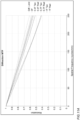
- FIG. 8A is a graph illustrating the modulation transfer function (MTF) for a lens system as illustrated in FIG. 7 at infinity conjugate.
- FIG. 8B shows longitudinal spherical aberration, astigmatic field curves, and distortion for a lens system as illustrated in FIG. 7 at infinity conjugate.
- MTF modulation transfer function
- FIG. 9A is a graph illustrating the modulation transfer function (MTF) for a lens system as illustrated in FIG. 7 at macro conjugate.
- FIG. 9B shows longitudinal spherical aberration, astigmatic field curves, and distortion for a lens system as illustrated in FIG. 7 at macro conjugate.
- MTF modulation transfer function
- the lens system 1010 may be shifted along the second axis (AX 2) independently of the two prisms 1041 and 1042 to allow refocusing of the lens system 1010 between Infinity conjugate and Macro conjugate. In some embodiments, the lens system 1010 may be shifted on one or more axes orthogonal to AX 2 to provide OIS functionality for the camera 1000. In various embodiments, lens elements 1001, 1002, 1003, and/or 1004 may be round/circular or rectangular, or some other shape. Note that in various embodiments, a lens system 1010 may include more or fewer refractive lens elements, and the lens elements may be configured or arranged differently.
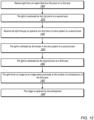
- FIG. 12 is a flowchart of a method for capturing images using embodiments of a camera as illustrated in FIGS. 1 through 11B , according to some embodiments.
- a first light folding element such as a prism on a first axis.
- the light is redirected by the first prism to a second axis.
- the light is received through an aperture at a first lens of a lens system on the second axis.
- the light is refracted by one or more lens elements of the lens system on the second axis to a second light folding element such as a prism.
- the light is redirected by the second light folding element to a third axis.
- the light forms an image at an image plane at or near the surface of a sensor module on the third axis.
- the image is captured by the photosensor.
- the lens system is independent of the first and second prisms.
- the camera may include an actuator component configured to move the lens system on one or more axes independently of the prisms to provide autofocus and/or OIS functionality for the camera.
- the components of the lens system referred to in FIG. 12 may be configured as illustrated in any of FIGS. 2 , 3 , 6 , 7 or 10 .
- FIGS. 2 , 3 , 6 , 7 or 10 the components of the lens system referred to in FIG. 12 may be configured as illustrated in any of FIGS. 2 , 3 , 6 , 7 or 10 .
- variations on the examples given in the Figures are possible while achieving similar optical results.
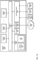
- FIG. 13 illustrates an example computing device, referred to as computer system 2000, that may include or host embodiments of a camera with a lens system as illustrated in FIGS. 1 through 12 .
- computer system 2000 may implement methods for controlling operations of the camera and/or for performing image processing of images captured with the camera.
- computer system 2000 may be any of various types of devices, including, but not limited to, a personal computer system, desktop computer, laptop, notebook, tablet or pad device, slate, or netbook computer, mainframe computer system, handheld computer, workstation, network computer, a camera, a set top box, a mobile device, a wireless phone, a smartphone, a consumer device, video game console, handheld video game device, application server, storage device, a television, a video recording device, a peripheral device such as a switch, modem, router, or in general any type of computing or electronic device.
- a personal computer system desktop computer, laptop, notebook, tablet or pad device, slate, or netbook computer
- mainframe computer system handheld computer
- workstation network computer
- a camera a set top box
- a mobile device a wireless phone
- smartphone a consumer device
- video game console handheld video game device
- application server storage device
- television a video recording device
- peripheral device such as a switch, modem, router, or in general any type of computing or electronic device.
- I/O interface 2030 may be configured to coordinate I/O traffic between processor 2010, system memory 2020, and any peripheral devices in the device, including network interface 2040 or other peripheral interfaces, such as input/output devices 2050.
- I/O interface 2030 may perform any necessary protocol, timing or other data transformations to convert data signals from one component (e.g., system memory 2020) into a format suitable for use by another component (e.g., processor 2010).
- I/O interface 2030 may include support for devices attached through various types of peripheral buses, such as a variant of the Peripheral Component Interconnect (PCI) bus standard or the Universal Serial Bus (USB) standard, for example.
- PCI Peripheral Component Interconnect
- USB Universal Serial Bus
- network interface 2040 may support communication via wired or wireless general data networks, such as any suitable type of Ethernet network, for example; via telecommunications/telephony networks such as analog voice networks or digital fiber communications networks; via storage area networks such as Fibre Channel SANs, or via any other suitable type of network and/or protocol.
- general data networks such as any suitable type of Ethernet network, for example; via telecommunications/telephony networks such as analog voice networks or digital fiber communications networks; via storage area networks such as Fibre Channel SANs, or via any other suitable type of network and/or protocol.
- Input/output devices 2050 may, in some embodiments, include one or more display terminals, keyboards, keypads, touchpads, scanning devices, voice or optical recognition devices, or any other devices suitable for entering or accessing data by computer system 2000. Multiple input/output devices 2050 may be present in computer system 2000 or may be distributed on various nodes of computer system 2000. In some embodiments, similar input/output devices may be separate from computer system 2000 and may interact with one or more nodes of computer system 2000 through a wired or wireless connection, such as over network interface 2040.
- instructions stored on a computer-accessible medium separate from computer system 2000 may be transmitted to computer system 2000 via transmission media or signals such as electrical, electromagnetic, or digital signals, conveyed via a communication medium such as a network and/or a wireless link.
- Various embodiments may further include receiving, sending or storing instructions and/or data implemented in accordance with the foregoing description upon a computer-accessible medium.
- a computer-accessible medium may include a non-transitory, computer-readable storage medium or memory medium such as magnetic or optical media, e.g., disk or DVD/CD-ROM, volatile or non-volatile media such as RAM (e.g. SDRAM, DDR, RDRAM, SRAM, etc.), ROM, etc.
- a computer-accessible medium may include transmission media or signals such as electrical, electromagnetic, or digital signals, conveyed via a communication medium such as network and/or a wireless link.
- the methods described herein may be implemented in software, hardware, or a combination thereof, in different embodiments.
- the order of the blocks of the methods may be changed, and various elements may be added, reordered, combined, omitted, modified, etc.
- Various modifications and changes may be made as would be obvious to a person skilled in the art having the benefit of this disclosure.
- the various embodiments described herein are meant to be illustrative and not limiting. Many variations, modifications, additions, and improvements are possible. Accordingly, plural instances may be provided for components described herein as a single instance. Boundaries between various components, operations and data stores are somewhat arbitrary, and particular operations are illustrated in the context of specific illustrative configurations.
Landscapes
- Physics & Mathematics (AREA)
- General Physics & Mathematics (AREA)
- Optics & Photonics (AREA)
- Engineering & Computer Science (AREA)
- General Engineering & Computer Science (AREA)
- Multimedia (AREA)
- Signal Processing (AREA)
- Lenses (AREA)
- Studio Devices (AREA)
Abstract
Description
- This disclosure relates generally to camera systems, and more specifically to small form factor camera and lens systems.
- The advent of small, mobile multipurpose devices such as smartphones and tablet or pad devices has resulted in a need for high-resolution, small form factor cameras that are lightweight, compact, and capable of capturing high resolution, high quality images at low F-numbers for integration in the devices. However, due to limitations of conventional camera technology, conventional small cameras used in such devices tend to capture images at lower resolutions and/or with lower image quality than can be achieved with larger, higher quality cameras. Achieving higher resolution with small package size cameras generally requires use of a photosensor with small pixel size and a good, compact imaging lens system. Advances in technology have achieved reduction of the pixel size in photosensors. However, as photosensors become more compact and powerful, demand for compact imaging lens systems with improved imaging quality performance has increased. In addition, there are increasing expectations for small form factor cameras to be equipped with higher pixel count and/or larger pixel size image sensors (one or both of which may require larger image sensors) while still maintaining a module height that is compact enough to fit into portable electronic devices. Thus, a challenge from an optical system design point of view is to provide an imaging lens system that is capable of capturing high brightness, high resolution images under the physical constraints imposed by small form factor cameras.
- Embodiments of the present disclosure may provide a folded camera that may, for example, be used in small form factor cameras. Embodiments of a folded camera are described that include two light folding elements (e.g., prisms) and an independent lens system located between the two prisms that includes an aperture stop and lens elements with refractive power mounted in a lens barrel. The prisms and lens system may collectively be referred to as an optical system. The prisms provide a "folded" optical axis for the camera, for example to reduce the Z-height of the camera. The lens system includes a lens stack including one or more refractive lens elements mounted in a lens barrel, and an aperture stop located at or in front of a first lens element in the stack. A first prism redirects light from an object field from a first axis (AX 1) to the lens system on a second axis (AX 2). The lens element(s) in the lens stack receive the light through the aperture stop and refract the light to a second prism that redirects the light onto a third axis (AX 3) on which a photosensor of the camera is disposed. The redirected light forms an image plane at or near the surface of the photosensor.
- The shapes, materials, and arrangements of the refractive lens elements in the lens stack may be selected to capture high resolution, high quality images while providing a sufficiently long back focal length to accommodate the second prism. Parameters and relationships of the lenses in the lens stack, including but not limited to lens shape, thickness, geometry, position, materials, spacing, and the surface shapes of certain lens elements, may be selected at least in part to reduce, compensate, or correct for optical aberrations and lens artifacts and effects across the field of view. In some embodiments, arrangements of power distribution, lens shapes, prism form factors, and lens materials may be selected to ensure that embodiments of the lens system provide low F-number (e.g., <= 2.4), 3x optical zoom, and high resolution imaging.
- The lens system may be configured in the camera to move on one or more axes independently of the prisms. The camera may include an actuator component configured to move the lens system on (parallel to) the second axis (AX 2) relative to and independently of the prisms to provide autofocus functionality for the camera. In some embodiments, the actuator may instead or also be configured to move the lens system on one or more axes perpendicular to the second axis (AX 2) relative to and independently of the prisms to provide optical image stabilization (OIS) functionality for the camera. In some embodiments, one or both of the prisms may be translated with respect to the second axis (AX 2) independently of the lens system and/or tilted with respect to the second axis (AX 2) independently of the lens system, for example to provide OIS functionality for the camera or to shift the image formed at an image plane at the photosensor.
- In some embodiments, the lens system may include a lens stack consisting of four lens elements with refractive power, in order from the object side to the image side of the camera: a first lens element with positive refractive power; a second lens element with positive refractive power; a third lens element with negative refractive power and an aspheric shape to correct chromatic aberration and field curvature; and a fourth lens element with a meniscus shape to correct field curvature and provide a low F-number.
- In some embodiments, the lens system may include a lens stack consisting of five lens elements with refractive power, in order from the object side to the image side of the camera: a first lens element with positive refractive power; a second lens element with positive refractive power; a third lens element with negative refractive power and an aspheric shape to correct chromatic aberration and field curvature; a fourth aspheric lens element configured as an air-space doublet with the third lens element that assists in the aberration correction provided by the third lens element; and a fifth lens element with a meniscus shape to correct field curvature and provide a low F-number.
- An aperture stop may be located in the lens system at the first lens element for controlling the brightness of the camera. Note that the power order, shape, or other optical characteristics of the refractive lens elements may be different in some embodiments, and some embodiments may include more or fewer refractive lens elements. In some embodiments, the folded camera may include an infrared (IR) filter to reduce or eliminate interference of environmental noise on the photosensor. The IR filter may, for example, be located between the second prism and the photosensor.
-
-
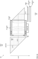
FIG. 1A illustrates components of a folded camera with two light folding elements and an independent lens system, according to some embodiments. -
FIG. 1B illustrates movements of the lens system relative to the light folding elements in a camera as illustrated inFIG. 1A , according to some embodiments. -
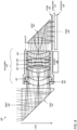
FIG. 2 is a cross-sectional illustration of a folded camera with four refractive lens elements in the lens system, according to some embodiments. -
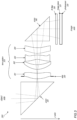
FIG. 3 is a diagram illustrating a lens system that includes four refractive lens elements, according to some embodiments. -
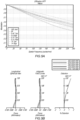
FIG. 4A is a graph illustrating the modulation transfer function (MTF) for a lens system as illustrated inFIG. 3 at infinity conjugate. -
FIG. 4B shows longitudinal spherical aberration, astigmatic field curves, and distortion for a lens system as illustrated inFIG. 3 at infinity conjugate. -
FIG. 5A is a graph illustrating the modulation transfer function (MTF) for a lens system as illustrated inFIG. 3 at macro conjugate. -
FIG. 5B shows longitudinal spherical aberration, astigmatic field curves, and distortion for a lens system as illustrated inFIG. 3 at macro conjugate. -
FIG. 6 is a cross-sectional illustration of a folded camera with five refractive lens elements in the lens system, according to some embodiments. -
FIG. 7 is a diagram illustrating a lens system that includes five refractive lens elements, according to some embodiments. -
FIG. 8A is a graph illustrating the modulation transfer function (MTF) for a lens system as illustrated inFIG. 7 at infinity conjugate. -
FIG. 8B shows longitudinal spherical aberration, astigmatic field curves, and distortion for a lens system as illustrated inFIG. 7 at infinity conjugate. -
FIG. 9A is a graph illustrating the modulation transfer function (MTF) for a lens system as illustrated inFIG. 7 at macro conjugate. -
FIG. 9B shows longitudinal spherical aberration, astigmatic field curves, and distortion for a lens system as illustrated inFIG. 7 at macro conjugate. -
FIG. 10 is a diagram illustrating a lens system that includes four refractive lens elements, according to some embodiments. -
FIG. 11A is a graph illustrating the modulation transfer function (MTF) for a lens system as illustrated inFIG. 10 . -
FIG. 11B shows longitudinal spherical aberration, astigmatic field curves, and distortion for a lens system as illustrated inFIG. 10 . -
FIG. 12 is a flowchart of a method for capturing images using embodiments of a camera as illustrated inFIGS. 1 through 11B , according to some embodiments. -
FIG. 13 illustrates an example computer system that may be used in embodiments. - This specification includes references to "one embodiment" or "an embodiment." The appearances of the phrases "in one embodiment" or "in an embodiment" do not necessarily refer to the same embodiment. Particular features, structures, or characteristics may be combined in any suitable manner consistent with this disclosure.
- "Comprising." This term is open-ended. As used in the appended claims, this term does not foreclose additional structure or steps. Consider a claim that recites: "An apparatus comprising one or more processor units ...". Such a claim does not foreclose the apparatus from including additional components (e.g., a network interface unit, graphics circuitry, etc.).
- "Configured To." Various units, circuits, or other components may be described or claimed as "configured to" perform a task or tasks. In such contexts, "configured to" is used to connote structure by indicating that the units/circuits/components include structure (e.g., circuitry) that performs those task or tasks during operation. As such, the unit/circuit/component can be said to be configured to perform the task even when the specified unit/circuit/component is not currently operational (e.g., is not on). The units/circuits/components used with the "configured to" language include hardware-for example, circuits, memory storing program instructions executable to implement the operation, etc. Reciting that a unit/circuit/component is "configured to" perform one or more tasks is expressly intended not to invoke 35 U.S.C. § 112, sixth paragraph, for that unit/circuit/component. Additionally, "configured to" can include generic structure (e.g., generic circuitry) that is manipulated by software and/or firmware (e.g., an FPGA or a general-purpose processor executing software) to operate in manner that is capable of performing the task(s) at issue. "Configure to" may also include adapting a manufacturing process (e.g., a semiconductor fabrication facility) to fabricate devices (e.g., integrated circuits) that are adapted to implement or perform one or more tasks.
- "First," "Second," etc. As used herein, these terms are used as labels for nouns that they precede, and do not imply any type of ordering (e.g., spatial, temporal, logical, etc.). For example, a buffer circuit may be described herein as performing write operations for "first" and "second" values. The terms "first" and "second" do not necessarily imply that the first value must be written before the second value.
- "Based On." As used herein, this term is used to describe one or more factors that affect a determination. This term does not foreclose additional factors that may affect a determination. That is, a determination may be solely based on those factors or based, at least in part, on those factors. Consider the phrase "determine A based on B." While in this case, B is a factor that affects the determination of A, such a phrase does not foreclose the determination of A from also being based on C. In other instances, A may be determined based solely on B.
- Embodiments of a folded camera are described that include two light folding elements (e.g., prisms) and an independent lens system located between the two prisms that includes an aperture stop and lens elements with refractive power mounted in a barrel. The prisms and lens system may collectively be referred to as an optical system.
FIG. 1A illustrates components of a foldedcamera 100 with twoprisms 141 and 142, and anindependent lens system 110, according to some embodiments. Theprisms 141 and 142 provide a "folded" optical axis for thecamera 100, for example to reduce the Z-height of thecamera 100. Thelens system 110 includes alens stack 114 including one or more refractive lens elements mounted in alens barrel 112, and anaperture stop 130 located at or in front of a first lens element in thestack 114. Afirst prism 141 redirects light from an object field from a first axis (AX 1) to thelens system 110 on a second axis (AX 2). The lens element(s) in thelens stack 114 receive the light through theaperture stop 130 and refract the light to a second prism 142 that redirects the light onto a third axis (AX 3) on which aphotosensor 120 of thecamera 100 is disposed. The redirected light forms an image at animage plane 121 at or near the surface of thephotosensor 120. - The shapes, materials, and arrangements of the refractive lens elements in the
lens stack 114 may be selected to capture high resolution, high quality images while providing a sufficiently long back focal length to accommodate the second prism 142. Thecamera 100 may, but does not necessarily, include an infrared (IR)filter 150, for example located between the second prism 142 and thephotosensor 120. -
FIG. 1B illustrates movements of thelens system 110 independently of and relative to theprisms 141 and 142 in acamera 100 as illustrated inFIG. 1A , according to some embodiments. In some embodiments, thecamera 100 may include anactuator 160 component or components configured to move thelens system 110 on (parallel to) the second axis (AX 2) relative to and independently of theprisms 141 and 142 to provide autofocus functionality for thecamera 100. In some embodiments, theactuator 160 component(s) may instead or also be configured to move thelens system 110 on one or more axes orthogonal to the second axis (AX 2) relative to and independently of theprisms 141 and 142 to provide optical image stabilization (OIS) functionality for thecamera 100. While not shown, in some embodiments, one or both of theprisms 141 and 142 may be translated with respect to the second axis (AX 2) independently of thelens system 110 and/or tilted with respect to the second axis (AX 2) independently of thelens system 110, for example to provide OIS functionality for thecamera 110 or to shift the image formed at animage plane 121 at thephotosensor 120. - Embodiments of a lens system for a folded camera as described herein are configured with a long back focal length (the distance from the last refractive lens element to the image plane) to provide space for a second light folding element (e.g., a second prism). In addition, arrangements of power distribution, lens shapes, prism form factors, and lens materials may be selected to ensure that embodiments of the lens system provide low F-number (e.g., <= 2.4), 3x optical zoom, and high resolution imaging.
- Embodiments of the folded camera as described herein may be implemented in a small package size while still capturing sharp, high-resolution images, making embodiments of the camera suitable for use in small and/or mobile multipurpose devices such as cell phones, smartphones, pad or tablet computing devices, laptop, netbook, notebook, subnotebook, and ultrabook computers, and so on.
FIG. 13 illustrates an example device that may include one or more small form factor cameras that use embodiments of the camera as described herein. However, note that aspects of the camera (e.g., the lens system, prisms, and photosensor) may be scaled up or down to provide cameras with larger or smaller package sizes. In addition, embodiments of the camera may be implemented as stand-alone digital cameras. In addition to still (single frame capture) camera applications, embodiments of the camera may be adapted for use in video camera applications. -
FIG. 2 is a cross-sectional illustration of a folded camera with four refractive lens elements in the lens system, according to some embodiments.FIG. 2 shows anexample camera 200 including twoprisms camera 200 and an example embodiment of alens system 210 with four refractive lens elements 201-204 located between theprisms lens barrel 212, with anaperture stop 230 located at or in front of the first (object side)lens element 201. While embodiments are generally described as using prisms to fold the optical axis, other methods may be used to fold the optical axis, including but not limited to mirrors. Thefirst prism 241 folds the optical axis from a first axis (AX 1) that is parallel to the incoming light direction to a second axis (AX 2) that is orthogonal to the incoming light direction. Thesecond prism 242 folds the optical axis from the second axis (AX 2) that is orthogonal to the incoming light direction to a third axis (AX 3) that is parallel to the incoming light direction. - The
camera 200 also includes aphotosensor 220, and may also include an optional infrared (IR) filter. Acamera 200 including an embodiment of thelens system 210 as illustrated inFIG. 2 may, for example, be implemented in portable electronic devices such as mobile phones and tablets. Embodiments of thelens system 210 may provide a low F-number (<= 2.4), 3x optical zoom, and high resolution imaging. - In some embodiments, the
camera 200 may include anactuator 260 component or components configured to move thelens system 210 on (parallel to) the second axis (AX 2) relative to and independently of theprisms camera 200. In some embodiments, theactuator 260 component(s) may instead or also be configured to move thelens system 210 on one or more axes orthogonal to the second axis (AX 2) relative to and independently of theprisms camera 200. Various types of mechanical, magnetic, or other actuator technology may be used in various embodiments. In some embodiments, one or both of theprisms lens system 210 and/or tilted with respect to the second axis (AX 2) independently of thelens system 210, for example to provide OIS functionality for thecamera 210 or to shift the image formed at animage plane 221 at thephotosensor 220. - As shown in the example of
FIG. 2 , embodiments of thelens system 210 may include four lens elements 201-204 with refractive power. Note, however, that some embodiments may include more or fewer refractive lens elements. Some embodiments of thelens system 210 may provide a 35 mm equivalent focal length in the range of 80 - 200 mm and less than 6.5 mm of Z-height to fit in a wide variety of portable electronics devices. With proper arrangement of materials and lens powers, embodiments of thelens system 210 are capable of capturing high brightness photographs or video frames with near diffraction-limited image quality. - As illustrated in the
example camera 200 ofFIG. 2 , thelens system 210 may include four lens elements 201-204 with refractive power, in order from the object side to the image side of the camera 200: afirst lens element 201 with positive refractive power; asecond lens element 202 with positive refractive power; athird lens element 203 with negative refractive power and an aspheric shape to correct chromatic aberration and field curvature; and afourth lens element 204 with a meniscus shape to correct field curvature and provide a low F-number. At least one of the refractive lens elements may be formed of lightweight polymer or plastic material. At least two of the refractive lens elements may be formed of materials with different Abbe numbers. Anaperture stop 230 may be located in thelens system 210 at thefirst lens element 201 for controlling the brightness of thecamera 200. Note that the power order, shape, or other optical characteristics of the refractive lens elements may be different in some embodiments, and some embodiments may include more or fewer refractive lens elements. - In some embodiments, the
camera 200 includes two right-angle prisms camera 200. In some embodiments, one or both of the prisms may be shifted or tilted relative to the position of thelens system 210 to provide autofocus and/or OIS functionality for thecamera 200. In some embodiments, theaperture stop 230 is integrated in thelens system 210 to control brightness in thecamera 200. Integrating thestop 230 in thelens system 210 enables thelens system 210 to be isolated from and moved independently with relation to theprisms aperture stop 230 may be fixed; the diameter of thestop 230 may be chosen according to system requirements. However, in some embodiments, the aperture stop may be adjustable. - In some embodiments, the
camera 200 includes anIR filter 250, for example located between lightfolding element 242 andphotosensor 220, to reduce or eliminate interference of environmental noises on thesensor 220. - Camera 200 Z-height is sensitive to
barrel 212 diameter. In some embodiments, to provide a desired Z-height for aparticular camera 200 application, the structure of thebarrel 212 may be modified. For example, in various embodiments of acamera 200, thebarrel 212 may be truncated, may be tapered, may be single-sided, and/or may have a reverse assembly structure. -
FIG. 3 is a diagram illustrating a lens system that includes four refractive lens elements, according to some embodiments. Acamera 300 may include aphotosensor 320, two light folding elements (e.g.,prisms 341 and 342), and anindependent lens system 310 located between the twoprisms aperture stop 330 and lens elements with refractive power mounted in a lens barrel. The prisms provide a "folded" optical axis for the camera, for example to reduce the Z-height of the camera. Thelens system 310 includes anaperture stop 330 to control system brightness while maintaining an integrated lens system that is independent of the twoprisms camera 300 may, but does not necessarily, include an infrared (IR)filter 350, for example located between thesecond prism 342 and thephotosensor 320. - The
example lens system 310 shown inFIG. 3 includes a lens stack consisting of four refractive elements 301-304 that provide a low F-number (<= F/2.4), 3x optical zoom, and high resolution imaging.Lenses lens Lens 303 has negative refractive power, and an aspheric shape to correct chromatic aberration and field curvature.Lens 304 is a meniscus lens to correct field curvature and enable low F-number operation of thecamera 300. In some embodiments,lens 304 may have low positive refractive power. - In some embodiments, the
lens system 310 may be shifted alongAX 2 independently of the twoprisms lens system 310 between Infinity conjugate and Macro conjugate. In some embodiments, thelens system 310 may be shifted on one or more axes orthogonal toAX 2 to provide OIS functionality for thecamera 300. In various embodiments,lens elements lens system 310 may include more or fewer refractive lens elements, and the lens elements may be configured or arranged differently. - In some embodiments, one or both of the
prisms lens system 310 along one or more axes by a mechanical actuator mechanism to facilitate autofocus functionality for thelens system 310 between Infinity conjugate and Macro conjugate. In some embodiments, one or both of theprisms lens system 310 and/or tilted with respect to the second axis (AX 2) independently of thelens system 342 by a mechanical actuator mechanism, for example to provide OIS functionality for thecamera 310 or to shift the image formed at animage plane 321 at thephotosensor 320. -
FIG. 4A is a graph illustrating the modulation transfer function (MTF) for a lens system as illustrated inFIG. 3 at infinity conjugate.FIG. 4B shows longitudinal spherical aberration, astigmatic field curves, and distortion for a lens system as illustrated inFIG. 3 at infinity conjugate. -
FIG. 5A is a graph illustrating the modulation transfer function (MTF) for a lens system as illustrated inFIG. 3 at macro conjugate.FIG. 5B shows longitudinal spherical aberration, astigmatic field curves, and distortion for a lens system as illustrated inFIG. 3 at macro conjugate. -
FIG. 6 is a cross-sectional illustration of a folded camera with five refractive lens elements in the lens system, according to some embodiments.FIG. 6 shows anexample camera 600 including twoprisms camera 600 and an example embodiment of alens system 610 with five refractive lens elements 601-605 located between theprisms lens barrel 612, with anaperture stop 630 located at or in front of the first (object side)lens element 601. While embodiments are generally described as using prisms to fold the optical axis, other methods may be used to fold the optical axis, including but not limited to mirrors. Thefirst prism 641 folds the optical axis from a first axis (AX 1) that is parallel to the incoming light direction to a second axis (AX 2) that is orthogonal to the incoming light direction. Thesecond prism 642 folds the optical axis from the second axis (AX 2) that is orthogonal to the incoming light direction to a third axis (AX 3) that is parallel to the incoming light direction. - The
camera 600 also includes aphotosensor 620, and may also include an optional infrared (IR) filter. Acamera 600 including an embodiment of thelens system 610 as illustrated inFIG. 6 may, for example, be implemented in portable electronic devices such as mobile phones and tablets. Embodiments of thelens system 610 may provide a low F-number (<= 2.4), 3x optical zoom, and high resolution imaging. - In some embodiments, the
camera 600 may include anactuator 660 component or components configured to move thelens system 610 on (parallel to) the second axis (AX 2) relative to and independently of theprisms camera 600. In some embodiments, theactuator 660 component(s) may instead or also be configured to move thelens system 610 on one or more axes orthogonal to the second axis (AX 2) relative to and independently of theprisms camera 600. Various types of mechanical, magnetic, or other actuator technology may be used in various embodiments. In some embodiments, one or both of theprisms lens system 610 and/or tilted with respect to the second axis (AX 2) independently of thelens system 610, for example to provide OIS functionality for thecamera 610 or to shift the image formed at an image plane 621 at thephotosensor 620. - As shown in the example of
FIG. 6 , embodiments of thelens system 610 may include five lens elements 601-605 with refractive power. Note, however, that some embodiments may include more or fewer refractive lens elements. Some embodiments of thelens system 610 may provide a 35 mm equivalent focal length in the range of 80 - 600 mm and less than 6.5 mm of Z-height to fit in a wide variety of portable electronics devices. With proper arrangement of materials and lens powers, embodiments of thelens system 610 are capable of capturing high brightness photographs or video frames with near diffraction-limited image quality. - As illustrated in the
example camera 600 ofFIG. 6 , thelens system 610 may include five lens elements 601-605 with refractive power, in order from the object side to the image side of the camera 600: afirst lens element 601 with positive refractive power; asecond lens element 602 with positive refractive power; athird lens element 603 with negative refractive power and an aspheric shape to correct chromatic aberration and field curvature; a fourthaspheric lens element 604 configured as an air-space doublet withlens element 603 that assists in the aberration correction provided bylens element 603; and afifth lens element 605 with a meniscus shape to correct field curvature and provide a low F-number. At least one of the refractive lens elements may be formed of lightweight polymer or plastic material. At least two of the refractive lens elements may be formed of materials with different Abbe numbers. Anaperture stop 630 may be located in thelens system 610 at thefirst lens element 601 for controlling the brightness of thecamera 600. Note that the power order, shape, or other optical characteristics of the refractive lens elements may be different in some embodiments, and some embodiments may include more or fewer refractive lens elements. - In some embodiments, the
camera 600 includes two right-angle prisms camera 600. In some embodiments, one or both of the prisms may be shifted or tilted relative to the position of thelens system 610 to provide autofocus and/or OIS functionality for thecamera 600. In some embodiments, theaperture stop 630 is integrated in thelens system 610 to control brightness in thecamera 600. Integrating thestop 630 in thelens system 610 enables thelens system 610 to be isolated from and moved independently with relation to theprisms aperture stop 630 may be fixed; the diameter of thestop 630 may be chosen according to system requirements. However, in some embodiments, the aperture stop may be adjustable. - In some embodiments, the
camera 600 includes anIR filter 650, for example located between lightfolding element 642 andphotosensor 620, to reduce or eliminate interference of environmental noises on thesensor 620. - Camera 600 Z-height is sensitive to
barrel 612 diameter. In some embodiments, to provide a desired Z-height for aparticular camera 600 application, the structure of thebarrel 612 may be modified. For example, in various embodiments of acamera 600, thebarrel 612 may be truncated, may be tapered, may be single-sided, and/or may have a reverse assembly structure. -
FIG. 7 is a diagram illustrating a lens system that includes five refractive lens elements in the lens system, according to some embodiments. Acamera 700 may include aphotosensor 720, two light folding elements (e.g.,prisms 741 and 742), and anindependent lens system 710 located between the twoprisms aperture stop 730 and lens elements with refractive power mounted in a lens barrel. The prisms provide a "folded" optical axis for the camera, for example to reduce the Z-height of the camera. Thelens system 710 includes anaperture stop 730 to control system brightness while maintaining an integrated lens system that is independent of the twoprisms camera 700 may, but does not necessarily, include an infrared (IR) filter 750, for example located between thesecond prism 742 and thephotosensor 720. - The
example lens system 710 shown inFIG. 7 includes a lens stack consisting of five refractive elements 701-705 that provide a low F-number (<= F/2.4), 3x optical zoom, and high resolution imaging.Lenses lens Lens 703 has negative refractive power, and an aspheric shape to correct chromatic aberration and field curvature.Lens 704 works as an air space doublet withlens 703 to provide aberration correction.Lens 705 is a meniscus lens to correct field curvature and enable low F-number operation of thecamera 700. In some embodiments,lens 705 may have low positive refractive power. - In some embodiments, the
lens system 710 may be shifted alongAX 2 independently of the twoprisms lens system 710 between Infinity conjugate and Macro conjugate. In some embodiments, thelens system 710 may be shifted on one or more axes orthogonal toAX 2 to provide OIS functionality for thecamera 700. In various embodiments,lens elements lens system 710 may include more or fewer refractive lens elements, and the lens elements may be configured or arranged differently. - In some embodiments, one or both of the
prisms lens system 710 along one or more axes by a mechanical actuator mechanism to facilitate autofocus functionality for thelens system 710. In some embodiments, one or both of theprisms lens system 710 and/or tilted with respect to the second axis (AX 2) independently of thelens system 742 by a mechanical actuator mechanism, for example to provide OIS functionality for thecamera 710 or to shift the image formed at an image plane 721 at thephotosensor 720. -
FIG. 8A is a graph illustrating the modulation transfer function (MTF) for a lens system as illustrated inFIG. 7 at infinity conjugate.FIG. 8B shows longitudinal spherical aberration, astigmatic field curves, and distortion for a lens system as illustrated inFIG. 7 at infinity conjugate. -
FIG. 9A is a graph illustrating the modulation transfer function (MTF) for a lens system as illustrated inFIG. 7 at macro conjugate.FIG. 9B shows longitudinal spherical aberration, astigmatic field curves, and distortion for a lens system as illustrated inFIG. 7 at macro conjugate. -
FIG. 10 is a diagram illustrating a lens system that includes four refractive lens elements, according to some embodiments. Acamera 1000 may include aphotosensor 1020, two light folding elements (e.g.,prisms 1041 and 1042), and anindependent lens system 1010 located between the twoprisms lens system 1010 includes an aperture stop 1030 to control system brightness while maintaining an integrated lens system that is independent of the twoprisms camera 1000 may, but does not necessarily, include an infrared (IR)filter 1050, for example located between thesecond prism 1042 and thephotosensor 1020. - The
example lens system 1010 shown inFIG. 10 includes a lens stack consisting of four refractive elements 1001-1004 that provide a low F-number (<= F/2.4), 3x optical zoom, and high resolution imaging.Lens 1001 has positive refractive power for light converging while being aspheric to control spherical aberration.Lens 1002 has negative refractive power and has an Abbe number that is less than 30.Lens 1003 is a meniscus lens, and has a concave object-side surface in the paraxial region and a convex image-side surface in the paraxial region.Lens 1004 is a meniscus lens to correct field curvature and enable low F-number operation of thecamera 1000. - In some embodiments, the
lens system 1010 may be shifted along the second axis (AX 2) independently of the twoprisms lens system 1010 between Infinity conjugate and Macro conjugate. In some embodiments, thelens system 1010 may be shifted on one or more axes orthogonal toAX 2 to provide OIS functionality for thecamera 1000. In various embodiments,lens elements lens system 1010 may include more or fewer refractive lens elements, and the lens elements may be configured or arranged differently. - In some embodiments, one or both of the
prisms lens system 1010 along one or more axes by a mechanical actuator mechanism to facilitate autofocus functionality for thelens system 1010. In some embodiments, one or both of theprisms lens system 1010 and/or tilted with respect to the second axis (AX 2) independently of thelens system 1042 by a mechanical actuator mechanism, for example to provide OIS functionality for thecamera 1010 or to shift the image formed at animage plane 1021 at thephotosensor 1020. -
FIG. 11A is a graph illustrating the modulation transfer function (MTF) for a lens system as illustrated inFIG. 10 .FIG. 11B shows longitudinal spherical aberration, astigmatic field curves, and distortion for a lens system as illustrated inFIG. 10 . -
FIG. 12 is a flowchart of a method for capturing images using embodiments of a camera as illustrated inFIGS. 1 through 11B , according to some embodiments. As indicated at 1900, light from an object field in front of the camera is received at a first light folding element such as a prism on a first axis. As indicated at 1910, the light is redirected by the first prism to a second axis. As indicated at 1920, the light is received through an aperture at a first lens of a lens system on the second axis. As indicated at 1930, the light is refracted by one or more lens elements of the lens system on the second axis to a second light folding element such as a prism. As indicated at 1940, the light is redirected by the second light folding element to a third axis. As indicated at 1950, the light forms an image at an image plane at or near the surface of a sensor module on the third axis. As indicated at 1960, the image is captured by the photosensor. The lens system is independent of the first and second prisms. The camera may include an actuator component configured to move the lens system on one or more axes independently of the prisms to provide autofocus and/or OIS functionality for the camera. - While not shown in
FIG. 12 , in some embodiments, the light may pass through an infrared filter that may for example be located between the second light folding element and the photosensor. In some embodiments, the aperture stop may be fixed; the diameter of the stop may be chosen according to system requirements. However, in some embodiments, the aperture stop may be adjustable. In some embodiments, one or both of the prisms are fixed. However, in some embodiments, one or both of the prisms may be shifted or tilted with respect to the second axis and independently of the lens system. - In some embodiments, the components of the lens system referred to in
FIG. 12 may be configured as illustrated in any ofFIGS. 2 ,3 ,6 ,7 or10 . However, note that variations on the examples given in the Figures are possible while achieving similar optical results. -
FIG. 13 illustrates an example computing device, referred to ascomputer system 2000, that may include or host embodiments of a camera with a lens system as illustrated inFIGS. 1 through 12 . In addition,computer system 2000 may implement methods for controlling operations of the camera and/or for performing image processing of images captured with the camera. In different embodiments,computer system 2000 may be any of various types of devices, including, but not limited to, a personal computer system, desktop computer, laptop, notebook, tablet or pad device, slate, or netbook computer, mainframe computer system, handheld computer, workstation, network computer, a camera, a set top box, a mobile device, a wireless phone, a smartphone, a consumer device, video game console, handheld video game device, application server, storage device, a television, a video recording device, a peripheral device such as a switch, modem, router, or in general any type of computing or electronic device. - In the illustrated embodiment,
computer system 2000 includes one or more processors 2010 coupled to asystem memory 2020 via an input/output (I/O)interface 2030.Computer system 2000 further includes anetwork interface 2040 coupled to I/O interface 2030, and one or more input/output devices 2050, such ascursor control device 2060,keyboard 2070, and display(s) 2080.Computer system 2000 may also include one ormore cameras 2090, for example one or more cameras as described above with respect toFIGS. 1 through 12 , which may also be coupled to I/O interface 2030, or one or more cameras as described above with respect toFIGS. 1 through 12 along with one or more other cameras such as conventional wide-field cameras. - In various embodiments,
computer system 2000 may be a uniprocessor system including one processor 2010, or a multiprocessor system including several processors 2010 (e.g., two, four, eight, or another suitable number). Processors 2010 may be any suitable processor capable of executing instructions. For example, in various embodiments processors 2010 may be general-purpose or embedded processors implementing any of a variety of instruction set architectures (ISAs), such as the x86, PowerPC, SPARC, or MIPS ISAs, or any other suitable ISA. In multiprocessor systems, each of processors 2010 may commonly, but not necessarily, implement the same ISA. -
System memory 2020 may be configured to storeprogram instructions 2022 and/ordata 2032 accessible by processor 2010. In various embodiments,system memory 2020 may be implemented using any suitable memory technology, such as static random access memory (SRAM), synchronous dynamic RAM (SDRAM), nonvolatile/Flash-type memory, or any other type of memory. In the illustrated embodiment,program instructions 2022 may be configured to implement various interfaces, methods and/or data for controlling operations ofcamera 2090 and for capturing and processing images withintegrated camera 2090 or other methods or data, for example interfaces and methods for capturing, displaying, processing, and storing images captured withcamera 2090. In some embodiments, program instructions and/or data may be received, sent or stored upon different types of computer-accessible media or on similar media separate fromsystem memory 2020 orcomputer system 2000. - In one embodiment, I/
O interface 2030 may be configured to coordinate I/O traffic between processor 2010,system memory 2020, and any peripheral devices in the device, includingnetwork interface 2040 or other peripheral interfaces, such as input/output devices 2050. In some embodiments, I/O interface 2030 may perform any necessary protocol, timing or other data transformations to convert data signals from one component (e.g., system memory 2020) into a format suitable for use by another component (e.g., processor 2010). In some embodiments, I/O interface 2030 may include support for devices attached through various types of peripheral buses, such as a variant of the Peripheral Component Interconnect (PCI) bus standard or the Universal Serial Bus (USB) standard, for example. In some embodiments, the function of I/O interface 2030 may be split into two or more separate components, such as a north bridge and a south bridge, for example. Also, in some embodiments some or all of the functionality of I/O interface 2030, such as an interface tosystem memory 2020, may be incorporated directly into processor 2010. -
Network interface 2040 may be configured to allow data to be exchanged betweencomputer system 2000 and other devices attached to a network 2085 (e.g., carrier or agent devices) or between nodes ofcomputer system 2000.Network 2085 may in various embodiments include one or more networks including but not limited to Local Area Networks (LANs) (e.g., an Ethernet or corporate network), Wide Area Networks (WANs) (e.g., the Internet), wireless data networks, some other electronic data network, or some combination thereof. In various embodiments,network interface 2040 may support communication via wired or wireless general data networks, such as any suitable type of Ethernet network, for example; via telecommunications/telephony networks such as analog voice networks or digital fiber communications networks; via storage area networks such as Fibre Channel SANs, or via any other suitable type of network and/or protocol. - Input/
output devices 2050 may, in some embodiments, include one or more display terminals, keyboards, keypads, touchpads, scanning devices, voice or optical recognition devices, or any other devices suitable for entering or accessing data bycomputer system 2000. Multiple input/output devices 2050 may be present incomputer system 2000 or may be distributed on various nodes ofcomputer system 2000. In some embodiments, similar input/output devices may be separate fromcomputer system 2000 and may interact with one or more nodes ofcomputer system 2000 through a wired or wireless connection, such as overnetwork interface 2040. - As shown in FIG. 16,
memory 2020 may includeprogram instructions 2022, which may be processor-executable to implement any element or action to supportintegrated camera 2090, including but not limited to image processing software and interface software for controllingcamera 2090. In some embodiments, images captured bycamera 2090 may be stored tomemory 2020. In addition, metadata for images captured bycamera 2090 may be stored tomemory 2020. - Those skilled in the art will appreciate that
computer system 2000 is merely illustrative and is not intended to limit the scope of embodiments. In particular, the computer system and devices may include any combination of hardware or software that can perform the indicated functions, including computers, network devices, Internet appliances, PDAs, wireless phones, pagers, video or still cameras, etc.Computer system 2000 may also be connected to other devices that are not illustrated, or instead may operate as a stand-alone system. In addition, the functionality provided by the illustrated components may in some embodiments be combined in fewer components or distributed in additional components. Similarly, in some embodiments, the functionality of some of the illustrated components may not be provided and/or other additional functionality may be available. - Those skilled in the art will also appreciate that, while various items are illustrated as being stored in memory or on storage while being used, these items or portions of them may be transferred between memory and other storage devices for purposes of memory management and data integrity. Alternatively, in other embodiments some or all of the software components may execute in memory on another device and communicate with the illustrated
computer system 2000 via inter-computer communication. Some or all of the system components or data structures may also be stored (e.g., as instructions or structured data) on a computer-accessible medium or a portable article to be read by an appropriate drive, various examples of which are described above. In some embodiments, instructions stored on a computer-accessible medium separate fromcomputer system 2000 may be transmitted tocomputer system 2000 via transmission media or signals such as electrical, electromagnetic, or digital signals, conveyed via a communication medium such as a network and/or a wireless link. Various embodiments may further include receiving, sending or storing instructions and/or data implemented in accordance with the foregoing description upon a computer-accessible medium. Generally speaking, a computer-accessible medium may include a non-transitory, computer-readable storage medium or memory medium such as magnetic or optical media, e.g., disk or DVD/CD-ROM, volatile or non-volatile media such as RAM (e.g. SDRAM, DDR, RDRAM, SRAM, etc.), ROM, etc. In some embodiments, a computer-accessible medium may include transmission media or signals such as electrical, electromagnetic, or digital signals, conveyed via a communication medium such as network and/or a wireless link. - The methods described herein may be implemented in software, hardware, or a combination thereof, in different embodiments. In addition, the order of the blocks of the methods may be changed, and various elements may be added, reordered, combined, omitted, modified, etc. Various modifications and changes may be made as would be obvious to a person skilled in the art having the benefit of this disclosure. The various embodiments described herein are meant to be illustrative and not limiting. Many variations, modifications, additions, and improvements are possible. Accordingly, plural instances may be provided for components described herein as a single instance. Boundaries between various components, operations and data stores are somewhat arbitrary, and particular operations are illustrated in the context of specific illustrative configurations. Other allocations of functionality are envisioned and may fall within the scope of claims that follow. Finally, structures and functionality presented as discrete components in the example configurations may be implemented as a combined structure or component. These and other variations, modifications, additions, and improvements may fall within the scope of embodiments as defined in the claims that follow.
- Aspects of the invention are disclosed in the following numbered clauses:
- 1. An optical system, comprising:
- a first light folding element;
- a second light folding element; and
- a lens system located between the first light folding element and the second light folding element, wherein the lens system includes a front aperture stop and a lens stack comprising one or more refractive lens elements;
- wherein the first light folding redirects light from an object field from a first axis to the lens system on a second axis;
- wherein the lens elements in the lens stack receive the light through the aperture stop and refract the light to the second light folding element;
- wherein the second light folding element redirects the light from the second axis onto a third axis to form an image of the object field at an image plane; and
- wherein the lens system is movable on two or more axes independently of the first and second light folding elements.
- 2. The optical system as recited in
clause 1, wherein the first and second light folding elements are prisms. - 3. The optical system as recited in
clause 1, wherein the lens system is movable on the second axis to provide autofocus functionality for the optical system. - 4. The optical system as recited in
clause 1, wherein the lens system is movable on one or more axes orthogonal to the second axis to provide optical image stabilization functionality for the optical system. - 5. The optical system as recited in
clause 1, wherein one or both of the light folding elements can be translated with respect to the second axis independently of the lens system. - 6. The optical system as recited in
clause 1, wherein one or both of the light folding elements can be tilted with respect to the second axis independently of the lens system. - 7. The optical system as recited in
clause 1, wherein the lens stack consists of four lens elements with refractive power, in order from an object side of the lens system to an image side of the lens system:- a first lens element with positive refractive power for converging light;
- a second lens element with positive refractive power for converging light;
- a third lens element with negative refractive power and an aspheric shape to correct chromatic aberration and field curvature; and
- a fourth lens element with a meniscus shape to correct field curvature;
- wherein F-number of the lens system is less than or equal to 2.4, and wherein the lens system provides a long back focal length to accommodate the second light folding element.
- 8. The optical system as recited in
clause 1, wherein the lens stack consists of five lens elements with refractive power, in order from an object side of the lens system to an image side of the lens system:- a first lens element with positive refractive power for converging light;
- a second lens element with positive refractive power for converging light;
- a third lens element with negative refractive power and an aspheric shape to correct chromatic aberration and field curvature;
- a fourth lens element with an aspheric shape configured as an air-space doublet with the third lens element to correct chromatic aberration and field curvature; and
- a fifth lens element with a meniscus shape to correct field curvature;
- wherein F-number of the lens system is less than or equal to 2.4, and wherein the lens system provides a long back focal length to accommodate the second light folding element.
- 9. The optical system as recited in
clause 1, wherein the lens stack consists of four lens elements with refractive power, in order from an object side of the lens system to an image side of the lens system:- a first lens element with positive refractive power and an aspheric shape to control spherical aberration;
- a second lens element with negative refractive power and an Abbe number that is less than 30;
- a third lens element with a meniscus shape that has a concave object-side surface in a paraxial region of the object-side surface and a convex image-side surface in a paraxial region of the image-side surface; and
- a fourth lens element with a meniscus shape to correct field curvature;
- wherein F-number of the lens system is less than or equal to 2.4, and wherein the lens system provides a long back focal length to accommodate the second light folding element.
- 10. A camera, comprising:
- a photosensor configured to capture light projected onto a surface of the photosensor;
- a first light folding element that redirects light received from an object field from a first axis to a second axis;
- a lens system that includes a front aperture stop and a lens stack comprising one or more refractive lens elements that refract the light on the second axis;
- a second light folding element that redirects the light refracted by the lens system from the second axis to a third axis to form an image of the object field at an image plane at or near a surface of the photosensor; and
- an actuator component configured to move the lens system on two or more axes independently of the first and second light folding elements.
- 11. The camera as recited in clause 10, wherein the first and second light folding elements are prisms.
- 12. The camera as recited in clause 10, wherein the lens system is movable on the second axis to provide autofocus functionality for the camera.
- 13. The camera as recited in clause 10, wherein the lens system is movable on one or more axes orthogonal to the second axis to provide optical image stabilization functionality for the camera.
- 14. The camera as recited in clause 10, wherein the camera further includes one or more actuator components configured to translate or tilt one or both of the light folding elements with respect to the second axis independently of the lens system.
- 15. The camera as recited in clause 10, wherein the lens stack consists of four lens elements with refractive power, in order from an object side of the lens system to an image side of the lens system:
- a first lens element with positive refractive power for converging light;
- a second lens element with positive refractive power for converging light;
- a third lens element with negative refractive power and an aspheric shape to correct chromatic aberration and field curvature; and
- a fourth lens element with a meniscus shape to correct field curvature;
- wherein F-number of the lens system is less than or equal to 2.4, and wherein the lens system provides a long back focal length to accommodate the second light folding element.
- 16. The camera as recited in clause 10, wherein the lens stack consists of five lens elements with refractive power, in order from an object side of the lens system to an image side of the lens system:
- a first lens element with positive refractive power for converging light;
- a second lens element with positive refractive power for converging light;
- a third lens element with negative refractive power and an aspheric shape to correct chromatic aberration and field curvature;
- a fourth lens element with an aspheric shape configured as an air-space doublet with the third lens element to correct chromatic aberration and field curvature; and
- a fifth lens element with a meniscus shape to correct field curvature;
- wherein F-number of the lens system is less than or equal to 2.4, and wherein the lens system provides a long back focal length to accommodate the second light folding element.
- 17. The camera as recited in clause 10, wherein the lens stack consists of four lens elements with refractive power, in order from an object side of the lens system to an image side of the lens system:
- a first lens element with positive refractive power and an aspheric shape to control spherical aberration;
- a second lens element with negative refractive power and an Abbe number that is less than 30;
- a third lens element with a meniscus shape that has a concave object-side surface in a paraxial region of the object-side surface and a convex image-side surface in a paraxial region of the image-side surface; and
- a fourth lens element with a meniscus shape to correct field curvature;
- wherein F-number of the lens system is less than or equal to 2.4, and wherein the lens system provides a long back focal length to accommodate the second light folding element.
- 18. A device, comprising:
- one or more processors;
- one or more cameras; and
- a memory comprising program instructions executable by at least one of the one or more processors to control operations of the one or more cameras;
- wherein at least one of the one or more cameras is a camera comprising:
- a photosensor configured to capture light projected onto a surface of the photosensor;
- a first light folding element that redirects light received from an object field from a first axis to a second axis;
- a lens system that includes a front aperture stop and a lens stack comprising one or more refractive lens elements that refract the light on the second axis;
- a second light folding element that redirects the light refracted by the lens system from the second axis to a third axis to form an image of the object field at an image plane at or near a surface of the photosensor; and
- an actuator component configured to move the optical system on two or more axes independently of the first and second light folding elements.
- 19. The device as recited in clause 18, wherein the lens system is movable on the second axis to provide autofocus functionality for the camera.
- 20. The device as recited in clause 18, wherein the lens system is movable on one or more axes orthogonal to the second axis to provide optical image stabilization functionality for the camera.
Claims (15)
- An optical system, comprising:a first light folding element;a second light folding element; anda lens system located between the first light folding element and the second light folding element;wherein the first light folding element redirects light from an object field from a first axis to the lens system on a second axis;wherein the lens elements in the lens stack receive the light through the aperture stop and refract the light to the second light folding element;wherein the second light folding element redirects the light from the second axis onto a third axis to form an image of the object field at an image plane; andwherein the lens system is movable on two or more axes independently of the first and second light folding elements,wherein the lens stack consists of four lens elements with refractive power, in order from an object side of the lens system to an image side of the lens system:a first lens element with positive refractive power for converging light;a second lens element with positive refractive power for converging light;a third lens element with negative refractive power and an aspheric shape to correct chromatic aberration and field curvature; anda fourth lens element with a meniscus shape to correct field curvature;wherein F-number of the lens system is less than or equal to 2.4, and wherein the lens system provides a long back focal length to accommodate the second light folding element.
- The optical system as recited in claim 1, wherein the first and second light folding elements are prisms.
- The optical system as recited in claim 1, wherein the second lens element has an Abbe number that is less than 30.
- The optical system as recited in any of claims 1-3, wherein two of the lens elements are formed of materials having different Abbe numbers.
- The optical system as recited in any of claims 1-4, wherein the lens system provides a 3x optical zoom.
- The optical system as recited in claim 1, wherein the lens system is movable on the second axis to provide autofocus functionality for the optical system.
- The optical system as recited in claim 1, wherein the lens system is movable on one or more axes orthogonal to the second axis to provide optical image stabilization functionality for the optical system.
- The optical system as recited in claim 1, wherein one or both of the light folding elements can be translated with respect to the second axis independently of the lens system.
- The optical system as recited in claim 1, wherein one or both of the light folding elements can be tilted with respect to the second axis independently of the lens system.
- A camera, comprising:a photosensor configured to capture light projected onto a surface of the photosensor; andan optical system as in any one of claims 1-5.
- The camera of claim 10, further comprising an actuator component configured to move the lens system on two or more axes independently of the first and second light folding elements.
- The camera as recited in claim 10, wherein the lens system is movable on the second axis to provide autofocus functionality for the camera.
- The camera as recited in claim 10, wherein the lens system is movable on one or more axes orthogonal to the second axis to provide optical image stabilization functionality for the camera.
- The camera as recited in claim 10, wherein the camera further includes one or more actuator components configured to translate or tilt one or both of the light folding elements with respect to the second axis independently of the lens system.
- A device to capture one or more images, comprising:one or more processors;one or more cameras as in any one of claims 10-14; anda memory comprising program instructions executable by at least one of the one or more processors to control operations of the one or more cameras.
Priority Applications (1)
| Application Number | Priority Date | Filing Date | Title |
|---|---|---|---|
| EP25208832.3A EP4657142A3 (en) | 2018-02-07 | 2019-02-04 | Folded camera |
Applications Claiming Priority (4)
| Application Number | Priority Date | Filing Date | Title |
|---|---|---|---|
| US201862627645P | 2018-02-07 | 2018-02-07 | |
| US16/264,463 US11061213B2 (en) | 2018-02-07 | 2019-01-31 | Folded camera |
| EP19705891.0A EP3735605A1 (en) | 2018-02-07 | 2019-02-04 | Folded camera |
| PCT/US2019/016523 WO2019156933A1 (en) | 2018-02-07 | 2019-02-04 | Folded camera |
Related Parent Applications (1)
| Application Number | Title | Priority Date | Filing Date |
|---|---|---|---|
| EP19705891.0A Division EP3735605A1 (en) | 2018-02-07 | 2019-02-04 | Folded camera |
Related Child Applications (2)
| Application Number | Title | Priority Date | Filing Date |
|---|---|---|---|
| EP25208832.3A Division EP4657142A3 (en) | 2018-02-07 | 2019-02-04 | Folded camera |
| EP25208832.3A Division-Into EP4657142A3 (en) | 2018-02-07 | 2019-02-04 | Folded camera |
Publications (2)
| Publication Number | Publication Date |
|---|---|
| EP4398019A1 true EP4398019A1 (en) | 2024-07-10 |
| EP4398019B1 EP4398019B1 (en) | 2025-12-31 |
Family
ID=67476602
Family Applications (3)
| Application Number | Title | Priority Date | Filing Date |
|---|---|---|---|
| EP25208832.3A Pending EP4657142A3 (en) | 2018-02-07 | 2019-02-04 | Folded camera |
| EP24176600.5A Active EP4398019B1 (en) | 2018-02-07 | 2019-02-04 | FOLDED CAMERA |
| EP19705891.0A Withdrawn EP3735605A1 (en) | 2018-02-07 | 2019-02-04 | Folded camera |
Family Applications Before (1)
| Application Number | Title | Priority Date | Filing Date |
|---|---|---|---|
| EP25208832.3A Pending EP4657142A3 (en) | 2018-02-07 | 2019-02-04 | Folded camera |
Family Applications After (1)
| Application Number | Title | Priority Date | Filing Date |
|---|---|---|---|
| EP19705891.0A Withdrawn EP3735605A1 (en) | 2018-02-07 | 2019-02-04 | Folded camera |
Country Status (4)
| Country | Link |
|---|---|
| US (3) | US11061213B2 (en) |
| EP (3) | EP4657142A3 (en) |
| CN (2) | CN115774317A (en) |
| WO (1) | WO2019156933A1 (en) |
Families Citing this family (36)
| Publication number | Priority date | Publication date | Assignee | Title |
|---|---|---|---|---|
| US10969652B2 (en) | 2018-01-10 | 2021-04-06 | Apple Inc. | Camera with folded optics having moveable lens |
| KR102632902B1 (en) | 2018-01-26 | 2024-02-05 | 애플 인크. | Folded camera with actuator for moving optics |
| US11061213B2 (en) | 2018-02-07 | 2021-07-13 | Apple Inc. | Folded camera |
| US11314147B1 (en) | 2018-05-31 | 2022-04-26 | Apple Inc. | Folded camera with actuator for moving optics |
| KR102776273B1 (en) * | 2018-09-14 | 2025-03-07 | 삼성전기주식회사 | Optical imaging system |
| US12585091B2 (en) | 2019-07-22 | 2026-03-24 | Apple Inc. | Camera including two light folding elements |
| US11714333B2 (en) | 2019-08-14 | 2023-08-01 | Guangzhou Luxvisions Innovations Technology Limited | Optical imaging apparatus capable of focusing |
| US11556047B2 (en) * | 2019-08-16 | 2023-01-17 | Tdk Taiwan Corp. | Optical member driving mechanism including matrix structure that corresponds to noise |
| KR102258604B1 (en) | 2019-09-10 | 2021-05-31 | 삼성전기주식회사 | Optical imaging system |
| TWI707188B (en) * | 2019-09-18 | 2020-10-11 | 大立光電股份有限公司 | Camera module and electronic device |
| US11243455B2 (en) * | 2019-09-25 | 2022-02-08 | Apple Inc. | Camera with folded optics |
| US11314031B2 (en) * | 2019-11-01 | 2022-04-26 | Tdk Taiwan Corp. | Optical element driving mechanism |
| CN111308672B (en) * | 2020-04-10 | 2025-06-17 | 浙江舜宇光学有限公司 | Optical imaging system |
| CN111505799B (en) * | 2020-04-14 | 2025-04-22 | 浙江舜宇光学有限公司 | Optical imaging lens set |
| KR102437800B1 (en) | 2020-05-19 | 2022-08-30 | 삼성전기주식회사 | Camera Module |
| US11726304B2 (en) * | 2020-05-26 | 2023-08-15 | Apple Inc. | Folded optical systems |
| CN119583941A (en) * | 2020-07-15 | 2025-03-07 | 核心光电有限公司 | System for correcting viewpoint aberrations in a scan folded camera and a multi-camera comprising such a scan folded camera |
| CN214586259U (en) * | 2020-07-24 | 2021-11-02 | 台湾东电化股份有限公司 | Optical system |
| CN214474350U (en) * | 2020-08-14 | 2021-10-22 | 台湾东电化股份有限公司 | Optical element driving mechanism |
| CN112034596B (en) * | 2020-09-24 | 2025-03-18 | 江西晶超光学有限公司 | Optical lens, imaging module and electronic device |
| CN114966919B (en) * | 2021-02-27 | 2023-04-28 | 华为技术有限公司 | Long-focus lens, camera module and electronic equipment |
| KR102613873B1 (en) * | 2021-04-30 | 2023-12-15 | 삼성전기주식회사 | Camera Module |
| DE102021112723B4 (en) | 2021-05-17 | 2025-10-30 | Schott Ag | Optical system for a periscope camera module and periscope camera module |
| US12192606B2 (en) * | 2021-10-07 | 2025-01-07 | Samsung Electro-Mechanics Co., Ltd. | Imaging lens system and camera module |
| EP4481460A4 (en) | 2022-05-26 | 2025-06-11 | Samsung Electronics Co., Ltd | Lens assembly and electronic device comprising same |
| EP4530693A4 (en) | 2022-05-27 | 2025-09-17 | Samsung Electronics Co Ltd | LENS ARRANGEMENT AND ELECTRONIC DEVICE THEREOF |
| US12523853B2 (en) | 2022-05-27 | 2026-01-13 | Samsung Electronics Co., Ltd. | Lens assembly and electronic device comprising same |
| US12177552B2 (en) | 2022-05-27 | 2024-12-24 | Samsung Electronics Co., Ltd. | Folded camera for reducing stray light and electronic device including the same |
| KR102842069B1 (en) * | 2022-09-27 | 2025-08-04 | 삼성전기주식회사 | Camera module |
| TW202429156A (en) * | 2022-12-11 | 2024-07-16 | 以色列商核心光電有限公司 | Refractive and hybrid lenses for compact folded tele cameras |
| JP7767481B2 (en) | 2023-02-24 | 2025-11-11 | キヤノン株式会社 | Optical system and imaging device |
| WO2024221180A1 (en) * | 2023-04-24 | 2024-10-31 | Huawei Technologies Co., Ltd. | Variable optical system and electronic device |
| TWI867520B (en) | 2023-05-05 | 2024-12-21 | 大立光電股份有限公司 | Photographing lens assembly, image capturing unit and electronic device |
| CN119071602A (en) * | 2023-05-31 | 2024-12-03 | 北京小米移动软件有限公司 | Terminal equipment, lenses and camera modules |
| EP4699346A4 (en) * | 2023-08-11 | 2026-07-08 | Samsung Electronics Co Ltd | DEVICE AND METHOD FOR SEAMLESS VIDEO RECORDING DURING A FLEX-STATE TRANSITION |
| WO2025059877A1 (en) * | 2023-09-19 | 2025-03-27 | Guangdong Oppo Mobile Telecommunications Corp., Ltd. | Imaging lens assembly, camera module, and imaging device |
Citations (2)
| Publication number | Priority date | Publication date | Assignee | Title |
|---|---|---|---|---|
| CN204422947U (en) * | 2014-03-07 | 2015-06-24 | 苹果公司 | Camera, folded lens system and related computing devices |
| US9829684B2 (en) * | 2014-08-10 | 2017-11-28 | Corephotonics Ltd. | Zoom dual-aperture camera with folded lens |
Family Cites Families (57)
| Publication number | Priority date | Publication date | Assignee | Title |
|---|---|---|---|---|
| US2649022A (en) | 1950-02-17 | 1953-08-18 | Angenieux Pierre | Wide-angle photographic objective lens assembly |
| US3014080A (en) | 1955-04-04 | 1961-12-19 | Glidden Co | Preparation of menthenyl and menthanyl compounds |
| JP3979353B2 (en) | 2002-08-02 | 2007-09-19 | セイコーエプソン株式会社 | Application method |
| JP3861815B2 (en) * | 2003-01-17 | 2006-12-27 | コニカミノルタフォトイメージング株式会社 | Camera with image stabilization function |
| JP2006154702A (en) * | 2004-10-29 | 2006-06-15 | Konica Minolta Opto Inc | Variable power optical system, imaging lens device and digital apparatus |
| JP4788953B2 (en) | 2005-11-16 | 2011-10-05 | ソニー株式会社 | Imaging device and zoom lens |
| EP1984774A4 (en) | 2006-02-06 | 2010-11-24 | Nokia Corp | OPTICAL IMAGE STABILIZER WITH A CARDANPRISMA |
| US7274518B1 (en) * | 2006-10-06 | 2007-09-25 | Largan Precision Co., Ltd. | Optical system for taking image |
| US8427761B2 (en) | 2009-03-10 | 2013-04-23 | Konica Minolta Opto, Inc. | Image pickup optical system, image pickup optical device, and digital equipment |
| JP5461981B2 (en) | 2009-12-25 | 2014-04-02 | 日本電産サンキョー株式会社 | Lens drive device |
| JP5579555B2 (en) * | 2010-09-24 | 2014-08-27 | Hoya株式会社 | Imaging optical system and imaging apparatus |
| TWI418876B (en) * | 2010-10-13 | 2013-12-11 | Largan Precision Co Ltd | Optical photographing system |
| US9172856B2 (en) | 2011-03-29 | 2015-10-27 | Microsoft Technology Licensing, Llc | Folded imaging path camera |
| US8670195B2 (en) | 2011-06-09 | 2014-03-11 | Panasonic Corporation | Lens actuator |
| JP2013125057A (en) * | 2011-12-13 | 2013-06-24 | Foxsemicon Integrated Technology Inc | Projection lens |
| TWI438476B (en) * | 2012-01-12 | 2014-05-21 | Largan Precision Co Ltd | Image capturing system |
| TWI459351B (en) | 2012-05-23 | 2014-11-01 | Macroblock Inc | Driving system and method thereof for driving a dot matrix led display |
| TWI570467B (en) | 2012-07-06 | 2017-02-11 | 大立光電股份有限公司 | Optical image pickup system group |
| JP5797627B2 (en) | 2012-09-25 | 2015-10-21 | Hoya株式会社 | Imaging device |
| US9726862B2 (en) * | 2012-11-08 | 2017-08-08 | DynaOptics LTD, A Public Limited CO. | Lens assemblies and actuators for optical systems and methods therefor |
| JP6114049B2 (en) | 2013-02-04 | 2017-04-12 | Hoya株式会社 | Imaging device |
| US9285566B2 (en) | 2013-08-08 | 2016-03-15 | Apple Inc. | Mirror tilt actuation |
| US9274311B2 (en) | 2014-01-13 | 2016-03-01 | Genius Electronic Optical Co., Ltd. | Compact narrow field of view lenses for mobile devices |
| JP6231416B2 (en) | 2014-03-20 | 2017-11-15 | Hoya株式会社 | Imaging device |
| US9383550B2 (en) | 2014-04-04 | 2016-07-05 | Qualcomm Incorporated | Auto-focus in low-profile folded optics multi-camera system |
| US9374516B2 (en) * | 2014-04-04 | 2016-06-21 | Qualcomm Incorporated | Auto-focus in low-profile folded optics multi-camera system |
| US9386222B2 (en) | 2014-06-20 | 2016-07-05 | Qualcomm Incorporated | Multi-camera system using folded optics free from parallax artifacts |
| US9549107B2 (en) | 2014-06-20 | 2017-01-17 | Qualcomm Incorporated | Autofocus for folded optic array cameras |
| WO2016007754A1 (en) | 2014-07-10 | 2016-01-14 | Qtrco, Inc. | Method and system for controlling actuators |
| US20160044247A1 (en) | 2014-08-10 | 2016-02-11 | Corephotonics Ltd. | Zoom dual-aperture camera with folded lens |
| KR102160867B1 (en) | 2015-04-02 | 2020-09-29 | 코어포토닉스 리미티드 | Dual voice coil motor structure in a dual-optical module camera |
| US10036895B2 (en) | 2015-05-28 | 2018-07-31 | Corephotonics Ltd. | Bi-directional stiffness for optical image stabilization in a dual-aperture digital camera |
| KR101992040B1 (en) | 2015-06-24 | 2019-06-21 | 코어포토닉스 리미티드 | Low-Profile 3-Axis Actuator for Foldable Lens Cameras |
| KR101717206B1 (en) | 2015-08-05 | 2017-03-17 | 에이에이씨 어쿠스틱 테크놀로지스(심천)컴퍼니 리미티드 | Camera lens module capable of optical image stabilization with the same |
| KR102340778B1 (en) | 2015-08-24 | 2021-12-20 | 엘지이노텍 주식회사 | Camera module |
| KR101993077B1 (en) | 2015-09-06 | 2019-06-25 | 코어포토닉스 리미티드 | Automatic focus and optical image stabilization by roll compensation of compact folding camera |
| JP6652734B2 (en) | 2015-11-20 | 2020-02-26 | ミツミ電機株式会社 | Lens driving device, camera module, and camera mounting device |
| KR20170075442A (en) * | 2015-12-23 | 2017-07-03 | 삼성전자주식회사 | Photographing apparatus module, user terminal comprising the photographing apparatus and method of operating the photographing apparatus module |
| JP6358752B2 (en) * | 2015-12-25 | 2018-07-18 | カンタツ株式会社 | Imaging lens |
| KR20170105236A (en) | 2016-03-09 | 2017-09-19 | 엘지전자 주식회사 | Image stabilization device |
| US9986223B2 (en) * | 2016-06-08 | 2018-05-29 | Qualcomm Incorporated | Folded optic passive depth sensing system |
| US9967547B2 (en) | 2016-06-08 | 2018-05-08 | Qualcomm Incorporated | Wafer level optics for folded optic passive depth sensing system |
| EP4485046B1 (en) | 2016-07-07 | 2026-06-10 | Corephotonics Ltd. | Linear ball guided voice coil motor for folded optic |
| US10303042B2 (en) | 2016-07-12 | 2019-05-28 | Tdk Taiwan Corp. | Lens driving module |
| TWI616675B (en) * | 2016-07-14 | 2018-03-01 | 大立光電股份有限公司 | Optical camera system group, image capturing device and electronic device |
| CN205942054U (en) | 2016-08-24 | 2017-02-08 | 宁波舜宇光电信息有限公司 | Periscopic module of making a video recording |
| TWI604218B (en) | 2016-09-30 | 2017-11-01 | 大立光電股份有限公司 | Optical imaging lens system, image capturing unit and electronic device |
| TWI594037B (en) * | 2016-11-24 | 2017-08-01 | 大立光電股份有限公司 | Photographing lens assembly, image capturing unit and electronic device |
| US10534194B2 (en) * | 2017-02-17 | 2020-01-14 | Samsung Electro-Mechanics Co., Ltd. | Reflecting module for OIS and camera module including the same |
| KR102145896B1 (en) | 2017-12-14 | 2020-08-19 | 엘지전자 주식회사 | Dual prism device, and camera including the same |
| US11029496B2 (en) | 2017-12-21 | 2021-06-08 | Apple Inc. | Folded lens system |
| US10969652B2 (en) | 2018-01-10 | 2021-04-06 | Apple Inc. | Camera with folded optics having moveable lens |
| CN110082984B (en) | 2018-01-25 | 2021-11-30 | 台湾东电化股份有限公司 | lens unit |
| KR102632902B1 (en) | 2018-01-26 | 2024-02-05 | 애플 인크. | Folded camera with actuator for moving optics |
| US11061213B2 (en) | 2018-02-07 | 2021-07-13 | Apple Inc. | Folded camera |
| US11314147B1 (en) | 2018-05-31 | 2022-04-26 | Apple Inc. | Folded camera with actuator for moving optics |
| US12585091B2 (en) | 2019-07-22 | 2026-03-24 | Apple Inc. | Camera including two light folding elements |
-
2019
- 2019-01-31 US US16/264,463 patent/US11061213B2/en active Active
- 2019-02-04 CN CN202211400560.7A patent/CN115774317A/en active Pending
- 2019-02-04 EP EP25208832.3A patent/EP4657142A3/en active Pending
- 2019-02-04 EP EP24176600.5A patent/EP4398019B1/en active Active
- 2019-02-04 CN CN201980011847.0A patent/CN111712749B/en active Active
- 2019-02-04 WO PCT/US2019/016523 patent/WO2019156933A1/en not_active Ceased
- 2019-02-04 EP EP19705891.0A patent/EP3735605A1/en not_active Withdrawn
-
2021
- 2021-07-09 US US17/371,732 patent/US11536936B2/en active Active
-
2022
- 2022-12-21 US US18/069,928 patent/US11754821B2/en active Active
Patent Citations (2)
| Publication number | Priority date | Publication date | Assignee | Title |
|---|---|---|---|---|
| CN204422947U (en) * | 2014-03-07 | 2015-06-24 | 苹果公司 | Camera, folded lens system and related computing devices |
| US9829684B2 (en) * | 2014-08-10 | 2017-11-28 | Corephotonics Ltd. | Zoom dual-aperture camera with folded lens |
Also Published As
| Publication number | Publication date |
|---|---|
| CN111712749B (en) | 2022-10-28 |
| US11061213B2 (en) | 2021-07-13 |
| EP4657142A3 (en) | 2026-01-28 |
| CN115774317A (en) | 2023-03-10 |
| EP4657142A2 (en) | 2025-12-03 |
| US20230119451A1 (en) | 2023-04-20 |
| US11754821B2 (en) | 2023-09-12 |
| US20190243112A1 (en) | 2019-08-08 |
| WO2019156933A1 (en) | 2019-08-15 |
| US11536936B2 (en) | 2022-12-27 |
| US20210333529A1 (en) | 2021-10-28 |
| EP4398019B1 (en) | 2025-12-31 |
| CN111712749A (en) | 2020-09-25 |
| EP3735605A1 (en) | 2020-11-11 |
Similar Documents
| Publication | Publication Date | Title |
|---|---|---|
| US11754821B2 (en) | Folded camera | |
| US12554106B2 (en) | Folded lens system | |
| US11635597B2 (en) | Folded lens system with three refractive lenses | |
| US11604337B2 (en) | Folded lens system with five refractive lenses | |
| EP3436862B1 (en) | Folded lens system with four refractive lenses | |
| US11988851B2 (en) | Lens system with optical actuator | |
| TWI830731B (en) | Lens system, camera, and imaging system | |
| KR20210091233A (en) | Light-Absorbing Flanged Lenses |
Legal Events
| Date | Code | Title | Description |
|---|---|---|---|
| PUAI | Public reference made under article 153(3) epc to a published international application that has entered the european phase |
Free format text: ORIGINAL CODE: 0009012 |
|
| STAA | Information on the status of an ep patent application or granted ep patent |
Free format text: STATUS: REQUEST FOR EXAMINATION WAS MADE |
|
| 17P | Request for examination filed |
Effective date: 20240517 |
|
| AC | Divisional application: reference to earlier application |
Ref document number: 3735605 Country of ref document: EP Kind code of ref document: P |
|
| AK | Designated contracting states |
Kind code of ref document: A1 Designated state(s): AL AT BE BG CH CY CZ DE DK EE ES FI FR GB GR HR HU IE IS IT LI LT LU LV MC MK MT NL NO PL PT RO RS SE SI SK SM TR |
|
| GRAP | Despatch of communication of intention to grant a patent |
Free format text: ORIGINAL CODE: EPIDOSNIGR1 |
|
| STAA | Information on the status of an ep patent application or granted ep patent |
Free format text: STATUS: GRANT OF PATENT IS INTENDED |
|
| INTG | Intention to grant announced |
Effective date: 20250305 |
|
| GRAJ | Information related to disapproval of communication of intention to grant by the applicant or resumption of examination proceedings by the epo deleted |
Free format text: ORIGINAL CODE: EPIDOSDIGR1 |
|
| STAA | Information on the status of an ep patent application or granted ep patent |
Free format text: STATUS: REQUEST FOR EXAMINATION WAS MADE |
|
| GRAP | Despatch of communication of intention to grant a patent |
Free format text: ORIGINAL CODE: EPIDOSNIGR1 |
|
| STAA | Information on the status of an ep patent application or granted ep patent |
Free format text: STATUS: GRANT OF PATENT IS INTENDED |
|
| INTC | Intention to grant announced (deleted) | ||
| INTG | Intention to grant announced |
Effective date: 20250520 |
|
| P01 | Opt-out of the competence of the unified patent court (upc) registered |
Free format text: CASE NUMBER: UPC_APP_9276_4398019/2025 Effective date: 20251007 |
|
| GRAS | Grant fee paid |
Free format text: ORIGINAL CODE: EPIDOSNIGR3 |
|
| GRAA | (expected) grant |
Free format text: ORIGINAL CODE: 0009210 |
|
| STAA | Information on the status of an ep patent application or granted ep patent |
Free format text: STATUS: THE PATENT HAS BEEN GRANTED |
|
| AC | Divisional application: reference to earlier application |
Ref document number: 3735605 Country of ref document: EP Kind code of ref document: P |
|
| AK | Designated contracting states |
Kind code of ref document: B1 Designated state(s): AL AT BE BG CH CY CZ DE DK EE ES FI FR GB GR HR HU IE IS IT LI LT LU LV MC MK MT NL NO PL PT RO RS SE SI SK SM TR |
|
| REG | Reference to a national code |
Ref country code: CH Ref legal event code: F10 Free format text: ST27 STATUS EVENT CODE: U-0-0-F10-F00 (AS PROVIDED BY THE NATIONAL OFFICE) Effective date: 20251231 Ref country code: GB Ref legal event code: FG4D |
|
| REG | Reference to a national code |
Ref country code: DE Ref legal event code: R096 Ref document number: 602019080036 Country of ref document: DE |
|
| REG | Reference to a national code |
Ref country code: IE Ref legal event code: FG4D |
|
| PGFP | Annual fee paid to national office [announced via postgrant information from national office to epo] |
Ref country code: GB Payment date: 20260130 Year of fee payment: 8 |
|
| REG | Reference to a national code |
Ref country code: LT Ref legal event code: MG9D |
|
| PG25 | Lapsed in a contracting state [announced via postgrant information from national office to epo] |
Ref country code: NO Free format text: LAPSE BECAUSE OF FAILURE TO SUBMIT A TRANSLATION OF THE DESCRIPTION OR TO PAY THE FEE WITHIN THE PRESCRIBED TIME-LIMIT Effective date: 20260331 |
|
| PGFP | Annual fee paid to national office [announced via postgrant information from national office to epo] |
Ref country code: DE Payment date: 20260130 Year of fee payment: 8 |
|
| PG25 | Lapsed in a contracting state [announced via postgrant information from national office to epo] |
Ref country code: HR Free format text: LAPSE BECAUSE OF FAILURE TO SUBMIT A TRANSLATION OF THE DESCRIPTION OR TO PAY THE FEE WITHIN THE PRESCRIBED TIME-LIMIT Effective date: 20251231 Ref country code: FI Free format text: LAPSE BECAUSE OF FAILURE TO SUBMIT A TRANSLATION OF THE DESCRIPTION OR TO PAY THE FEE WITHIN THE PRESCRIBED TIME-LIMIT Effective date: 20251231 |
|
| PG25 | Lapsed in a contracting state [announced via postgrant information from national office to epo] |
Ref country code: RS Free format text: LAPSE BECAUSE OF FAILURE TO SUBMIT A TRANSLATION OF THE DESCRIPTION OR TO PAY THE FEE WITHIN THE PRESCRIBED TIME-LIMIT Effective date: 20260331 |
|
| PG25 | Lapsed in a contracting state [announced via postgrant information from national office to epo] |
Ref country code: LV Free format text: LAPSE BECAUSE OF FAILURE TO SUBMIT A TRANSLATION OF THE DESCRIPTION OR TO PAY THE FEE WITHIN THE PRESCRIBED TIME-LIMIT Effective date: 20251231 |
|
| PG25 | Lapsed in a contracting state [announced via postgrant information from national office to epo] |
Ref country code: BG Free format text: LAPSE BECAUSE OF FAILURE TO SUBMIT A TRANSLATION OF THE DESCRIPTION OR TO PAY THE FEE WITHIN THE PRESCRIBED TIME-LIMIT Effective date: 20251231 |
|
| REG | Reference to a national code |
Ref country code: NL Ref legal event code: MP Effective date: 20251231 |
|
| REG | Reference to a national code |
Ref country code: AT Ref legal event code: MK05 Ref document number: 1873914 Country of ref document: AT Kind code of ref document: T Effective date: 20251231 |
|
| PG25 | Lapsed in a contracting state [announced via postgrant information from national office to epo] |
Ref country code: NL Free format text: LAPSE BECAUSE OF FAILURE TO SUBMIT A TRANSLATION OF THE DESCRIPTION OR TO PAY THE FEE WITHIN THE PRESCRIBED TIME-LIMIT Effective date: 20251231 |
|
| PG25 | Lapsed in a contracting state [announced via postgrant information from national office to epo] |
Ref country code: LT Free format text: LAPSE BECAUSE OF FAILURE TO SUBMIT A TRANSLATION OF THE DESCRIPTION OR TO PAY THE FEE WITHIN THE PRESCRIBED TIME-LIMIT Effective date: 20251231 |
|
| PG25 | Lapsed in a contracting state [announced via postgrant information from national office to epo] |
Ref country code: SM Free format text: LAPSE BECAUSE OF FAILURE TO SUBMIT A TRANSLATION OF THE DESCRIPTION OR TO PAY THE FEE WITHIN THE PRESCRIBED TIME-LIMIT Effective date: 20251231 |
|
| PG25 | Lapsed in a contracting state [announced via postgrant information from national office to epo] |
Ref country code: ES Free format text: LAPSE BECAUSE OF FAILURE TO SUBMIT A TRANSLATION OF THE DESCRIPTION OR TO PAY THE FEE WITHIN THE PRESCRIBED TIME-LIMIT Effective date: 20251231 |
|
| PG25 | Lapsed in a contracting state [announced via postgrant information from national office to epo] |
Ref country code: PL Free format text: LAPSE BECAUSE OF FAILURE TO SUBMIT A TRANSLATION OF THE DESCRIPTION OR TO PAY THE FEE WITHIN THE PRESCRIBED TIME-LIMIT Effective date: 20251231 |
|
| PG25 | Lapsed in a contracting state [announced via postgrant information from national office to epo] |
Ref country code: IT Free format text: LAPSE BECAUSE OF FAILURE TO SUBMIT A TRANSLATION OF THE DESCRIPTION OR TO PAY THE FEE WITHIN THE PRESCRIBED TIME-LIMIT Effective date: 20251231 |
|
| PG25 | Lapsed in a contracting state [announced via postgrant information from national office to epo] |
Ref country code: AT Free format text: LAPSE BECAUSE OF FAILURE TO SUBMIT A TRANSLATION OF THE DESCRIPTION OR TO PAY THE FEE WITHIN THE PRESCRIBED TIME-LIMIT Effective date: 20251231 |
|
| PG25 | Lapsed in a contracting state [announced via postgrant information from national office to epo] |
Ref country code: EE Free format text: LAPSE BECAUSE OF FAILURE TO SUBMIT A TRANSLATION OF THE DESCRIPTION OR TO PAY THE FEE WITHIN THE PRESCRIBED TIME-LIMIT Effective date: 20251231 |
|
| PG25 | Lapsed in a contracting state [announced via postgrant information from national office to epo] |
Ref country code: PT Free format text: LAPSE BECAUSE OF FAILURE TO SUBMIT A TRANSLATION OF THE DESCRIPTION OR TO PAY THE FEE WITHIN THE PRESCRIBED TIME-LIMIT Effective date: 20260430 Ref country code: IS Free format text: LAPSE BECAUSE OF FAILURE TO SUBMIT A TRANSLATION OF THE DESCRIPTION OR TO PAY THE FEE WITHIN THE PRESCRIBED TIME-LIMIT Effective date: 20260430 |
|
| PG25 | Lapsed in a contracting state [announced via postgrant information from national office to epo] |
Ref country code: CZ Free format text: LAPSE BECAUSE OF FAILURE TO SUBMIT A TRANSLATION OF THE DESCRIPTION OR TO PAY THE FEE WITHIN THE PRESCRIBED TIME-LIMIT Effective date: 20251231 |
|
| PG25 | Lapsed in a contracting state [announced via postgrant information from national office to epo] |
Ref country code: SK Free format text: LAPSE BECAUSE OF FAILURE TO SUBMIT A TRANSLATION OF THE DESCRIPTION OR TO PAY THE FEE WITHIN THE PRESCRIBED TIME-LIMIT Effective date: 20251231 |
|
| PG25 | Lapsed in a contracting state [announced via postgrant information from national office to epo] |
Ref country code: SE Free format text: LAPSE BECAUSE OF FAILURE TO SUBMIT A TRANSLATION OF THE DESCRIPTION OR TO PAY THE FEE WITHIN THE PRESCRIBED TIME-LIMIT Effective date: 20251231 |