EP4398019A1 - Gefaltete kamera - Google Patents
Gefaltete kamera Download PDFInfo
- Publication number
- EP4398019A1 EP4398019A1 EP24176600.5A EP24176600A EP4398019A1 EP 4398019 A1 EP4398019 A1 EP 4398019A1 EP 24176600 A EP24176600 A EP 24176600A EP 4398019 A1 EP4398019 A1 EP 4398019A1
- Authority
- EP
- European Patent Office
- Prior art keywords
- lens
- lens system
- camera
- light
- axis
- Prior art date
- Legal status (The legal status is an assumption and is not a legal conclusion. Google has not performed a legal analysis and makes no representation as to the accuracy of the status listed.)
- Granted
Links
Images


Classifications
-
- G—PHYSICS
- G02—OPTICS
- G02B—OPTICAL ELEMENTS, SYSTEMS OR APPARATUS
- G02B17/00—Systems with reflecting surfaces, with or without refracting elements
- G02B17/08—Catadioptric systems
-
- G—PHYSICS
- G02—OPTICS
- G02B—OPTICAL ELEMENTS, SYSTEMS OR APPARATUS
- G02B13/00—Optical objectives specially designed for the purposes specified below
- G02B13/001—Miniaturised objectives for electronic devices, e.g. portable telephones, webcams, PDAs, small digital cameras
- G02B13/0015—Miniaturised objectives for electronic devices, e.g. portable telephones, webcams, PDAs, small digital cameras characterised by the lens design
- G02B13/002—Miniaturised objectives for electronic devices, e.g. portable telephones, webcams, PDAs, small digital cameras characterised by the lens design having at least one aspherical surface
- G02B13/004—Miniaturised objectives for electronic devices, e.g. portable telephones, webcams, PDAs, small digital cameras characterised by the lens design having at least one aspherical surface having four lenses
-
- G—PHYSICS
- G02—OPTICS
- G02B—OPTICAL ELEMENTS, SYSTEMS OR APPARATUS
- G02B13/00—Optical objectives specially designed for the purposes specified below
- G02B13/001—Miniaturised objectives for electronic devices, e.g. portable telephones, webcams, PDAs, small digital cameras
- G02B13/0015—Miniaturised objectives for electronic devices, e.g. portable telephones, webcams, PDAs, small digital cameras characterised by the lens design
- G02B13/002—Miniaturised objectives for electronic devices, e.g. portable telephones, webcams, PDAs, small digital cameras characterised by the lens design having at least one aspherical surface
- G02B13/0045—Miniaturised objectives for electronic devices, e.g. portable telephones, webcams, PDAs, small digital cameras characterised by the lens design having at least one aspherical surface having five or more lenses
-
- G—PHYSICS
- G02—OPTICS
- G02B—OPTICAL ELEMENTS, SYSTEMS OR APPARATUS
- G02B13/00—Optical objectives specially designed for the purposes specified below
- G02B13/001—Miniaturised objectives for electronic devices, e.g. portable telephones, webcams, PDAs, small digital cameras
- G02B13/0055—Miniaturised objectives for electronic devices, e.g. portable telephones, webcams, PDAs, small digital cameras employing a special optical element
- G02B13/0065—Miniaturised objectives for electronic devices, e.g. portable telephones, webcams, PDAs, small digital cameras employing a special optical element having a beam-folding prism or mirror
-
- G—PHYSICS
- G02—OPTICS
- G02B—OPTICAL ELEMENTS, SYSTEMS OR APPARATUS
- G02B13/00—Optical objectives specially designed for the purposes specified below
- G02B13/001—Miniaturised objectives for electronic devices, e.g. portable telephones, webcams, PDAs, small digital cameras
- G02B13/009—Miniaturised objectives for electronic devices, e.g. portable telephones, webcams, PDAs, small digital cameras having zoom function
-
- G—PHYSICS
- G02—OPTICS
- G02B—OPTICAL ELEMENTS, SYSTEMS OR APPARATUS
- G02B13/00—Optical objectives specially designed for the purposes specified below
- G02B13/04—Reversed telephoto objectives
-
- G—PHYSICS
- G02—OPTICS
- G02B—OPTICAL ELEMENTS, SYSTEMS OR APPARATUS
- G02B27/00—Optical systems or apparatus not provided for by any of the groups G02B1/00 - G02B26/00, G02B30/00
- G02B27/64—Imaging systems using optical elements for stabilisation of the lateral and angular position of the image
- G02B27/646—Imaging systems using optical elements for stabilisation of the lateral and angular position of the image compensating for small deviations, e.g. due to vibration or shake
-
- G—PHYSICS
- G02—OPTICS
- G02B—OPTICAL ELEMENTS, SYSTEMS OR APPARATUS
- G02B7/00—Mountings, adjusting means, or light-tight connections, for optical elements
- G02B7/02—Mountings, adjusting means, or light-tight connections, for optical elements for lenses
- G02B7/04—Mountings, adjusting means, or light-tight connections, for optical elements for lenses with mechanism for focusing or varying magnification
- G02B7/09—Mountings, adjusting means, or light-tight connections, for optical elements for lenses with mechanism for focusing or varying magnification adapted for automatic focusing or varying magnification
-
- G—PHYSICS
- G02—OPTICS
- G02B—OPTICAL ELEMENTS, SYSTEMS OR APPARATUS
- G02B7/00—Mountings, adjusting means, or light-tight connections, for optical elements
- G02B7/02—Mountings, adjusting means, or light-tight connections, for optical elements for lenses
- G02B7/04—Mountings, adjusting means, or light-tight connections, for optical elements for lenses with mechanism for focusing or varying magnification
- G02B7/10—Mountings, adjusting means, or light-tight connections, for optical elements for lenses with mechanism for focusing or varying magnification by relative axial movement of several lenses, e.g. of varifocal objective lens
- G02B7/102—Mountings, adjusting means, or light-tight connections, for optical elements for lenses with mechanism for focusing or varying magnification by relative axial movement of several lenses, e.g. of varifocal objective lens controlled by a microcomputer
-
- G—PHYSICS
- G02—OPTICS
- G02B—OPTICAL ELEMENTS, SYSTEMS OR APPARATUS
- G02B7/00—Mountings, adjusting means, or light-tight connections, for optical elements
- G02B7/18—Mountings, adjusting means, or light-tight connections, for optical elements for prisms; for mirrors
- G02B7/1805—Mountings, adjusting means, or light-tight connections, for optical elements for prisms; for mirrors for prisms
-
- G—PHYSICS
- G02—OPTICS
- G02B—OPTICAL ELEMENTS, SYSTEMS OR APPARATUS
- G02B9/00—Optical objectives characterised both by the number of the components and their arrangements according to their sign, i.e. + or -
- G02B9/34—Optical objectives characterised both by the number of the components and their arrangements according to their sign, i.e. + or - having four components only
-
- G—PHYSICS
- G02—OPTICS
- G02B—OPTICAL ELEMENTS, SYSTEMS OR APPARATUS
- G02B9/00—Optical objectives characterised both by the number of the components and their arrangements according to their sign, i.e. + or -
- G02B9/60—Optical objectives characterised both by the number of the components and their arrangements according to their sign, i.e. + or - having five components only
-
- G—PHYSICS
- G03—PHOTOGRAPHY; CINEMATOGRAPHY; ANALOGOUS TECHNIQUES USING WAVES OTHER THAN OPTICAL WAVES; ELECTROGRAPHY; HOLOGRAPHY
- G03B—APPARATUS OR ARRANGEMENTS FOR TAKING PHOTOGRAPHS OR FOR PROJECTING OR VIEWING THEM; APPARATUS OR ARRANGEMENTS EMPLOYING ANALOGOUS TECHNIQUES USING WAVES OTHER THAN OPTICAL WAVES; ACCESSORIES THEREFOR
- G03B13/00—Viewfinders; Focusing aids for cameras; Means for focusing for cameras; Autofocus systems for cameras
- G03B13/32—Means for focusing
- G03B13/34—Power focusing
- G03B13/36—Autofocus systems
-
- G—PHYSICS
- G03—PHOTOGRAPHY; CINEMATOGRAPHY; ANALOGOUS TECHNIQUES USING WAVES OTHER THAN OPTICAL WAVES; ELECTROGRAPHY; HOLOGRAPHY
- G03B—APPARATUS OR ARRANGEMENTS FOR TAKING PHOTOGRAPHS OR FOR PROJECTING OR VIEWING THEM; APPARATUS OR ARRANGEMENTS EMPLOYING ANALOGOUS TECHNIQUES USING WAVES OTHER THAN OPTICAL WAVES; ACCESSORIES THEREFOR
- G03B5/00—Adjustment of optical system relative to image or object surface other than for focusing
- G03B5/02—Lateral adjustment of lens
-
- H—ELECTRICITY
- H04—ELECTRIC COMMUNICATION TECHNIQUE
- H04N—PICTORIAL COMMUNICATION, e.g. TELEVISION
- H04N23/00—Cameras or camera modules comprising electronic image sensors; Control thereof
- H04N23/60—Control of cameras or camera modules
- H04N23/68—Control of cameras or camera modules for stable pick-up of the scene, e.g. compensating for camera body vibrations
- H04N23/682—Vibration or motion blur correction
- H04N23/685—Vibration or motion blur correction performed by mechanical compensation
- H04N23/687—Vibration or motion blur correction performed by mechanical compensation by shifting the lens or sensor position
-
- G—PHYSICS
- G03—PHOTOGRAPHY; CINEMATOGRAPHY; ANALOGOUS TECHNIQUES USING WAVES OTHER THAN OPTICAL WAVES; ELECTROGRAPHY; HOLOGRAPHY
- G03B—APPARATUS OR ARRANGEMENTS FOR TAKING PHOTOGRAPHS OR FOR PROJECTING OR VIEWING THEM; APPARATUS OR ARRANGEMENTS EMPLOYING ANALOGOUS TECHNIQUES USING WAVES OTHER THAN OPTICAL WAVES; ACCESSORIES THEREFOR
- G03B2205/00—Adjustment of optical system relative to image or object surface other than for focusing
- G03B2205/0007—Movement of one or more optical elements for control of motion blur
Definitions
- This disclosure relates generally to camera systems, and more specifically to small form factor camera and lens systems.
- a challenge from an optical system design point of view is to provide an imaging lens system that is capable of capturing high brightness, high resolution images under the physical constraints imposed by small form factor cameras.
- Embodiments of the present disclosure may provide a folded camera that may, for example, be used in small form factor cameras.
- Embodiments of a folded camera are described that include two light folding elements (e.g., prisms) and an independent lens system located between the two prisms that includes an aperture stop and lens elements with refractive power mounted in a lens barrel.
- the prisms and lens system may collectively be referred to as an optical system.
- the prisms provide a "folded" optical axis for the camera, for example to reduce the Z-height of the camera.
- the lens system includes a lens stack including one or more refractive lens elements mounted in a lens barrel, and an aperture stop located at or in front of a first lens element in the stack.
- a first prism redirects light from an object field from a first axis (AX 1) to the lens system on a second axis (AX 2).
- the lens element(s) in the lens stack receive the light through the aperture stop and refract the light to a second prism that redirects the light onto a third axis (AX 3) on which a photosensor of the camera is disposed.
- the redirected light forms an image plane at or near the surface of the photosensor.
- the shapes, materials, and arrangements of the refractive lens elements in the lens stack may be selected to capture high resolution, high quality images while providing a sufficiently long back focal length to accommodate the second prism.
- Parameters and relationships of the lenses in the lens stack including but not limited to lens shape, thickness, geometry, position, materials, spacing, and the surface shapes of certain lens elements, may be selected at least in part to reduce, compensate, or correct for optical aberrations and lens artifacts and effects across the field of view.
- the lens system may be configured in the camera to move on one or more axes independently of the prisms.
- the camera may include an actuator component configured to move the lens system on (parallel to) the second axis (AX 2) relative to and independently of the prisms to provide autofocus functionality for the camera.
- the actuator may instead or also be configured to move the lens system on one or more axes perpendicular to the second axis (AX 2) relative to and independently of the prisms to provide optical image stabilization (OIS) functionality for the camera.
- OIS optical image stabilization
- one or both of the prisms may be translated with respect to the second axis (AX 2) independently of the lens system and/or tilted with respect to the second axis (AX 2) independently of the lens system, for example to provide OIS functionality for the camera or to shift the image formed at an image plane at the photosensor.
- the lens system may include a lens stack consisting of four lens elements with refractive power, in order from the object side to the image side of the camera: a first lens element with positive refractive power; a second lens element with positive refractive power; a third lens element with negative refractive power and an aspheric shape to correct chromatic aberration and field curvature; and a fourth lens element with a meniscus shape to correct field curvature and provide a low F-number.
- An aperture stop may be located in the lens system at the first lens element for controlling the brightness of the camera.
- the power order, shape, or other optical characteristics of the refractive lens elements may be different in some embodiments, and some embodiments may include more or fewer refractive lens elements.
- the folded camera may include an infrared (IR) filter to reduce or eliminate interference of environmental noise on the photosensor.
- the IR filter may, for example, be located between the second prism and the photosensor.
- a unit/circuit/component is “configured to” perform one or more tasks is expressly intended not to invoke 35 U.S.C. ⁇ 112, sixth paragraph, for that unit/circuit/component.
- "configured to” can include generic structure (e.g., generic circuitry) that is manipulated by software and/or firmware (e.g., an FPGA or a general-purpose processor executing software) to operate in manner that is capable of performing the task(s) at issue.
- "Configure to” may also include adapting a manufacturing process (e.g., a semiconductor fabrication facility) to fabricate devices (e.g., integrated circuits) that are adapted to implement or perform one or more tasks.
- this term is used to describe one or more factors that affect a determination. This term does not foreclose additional factors that may affect a determination. That is, a determination may be solely based on those factors or based, at least in part, on those factors.
- a determination may be solely based on those factors or based, at least in part, on those factors.
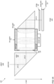
- the lens system 110 includes a lens stack 114 including one or more refractive lens elements mounted in a lens barrel 112, and an aperture stop 130 located at or in front of a first lens element in the stack 114.
- a first prism 141 redirects light from an object field from a first axis (AX 1) to the lens system 110 on a second axis (AX 2).
- the lens element(s) in the lens stack 114 receive the light through the aperture stop 130 and refract the light to a second prism 142 that redirects the light onto a third axis (AX 3) on which a photosensor 120 of the camera 100 is disposed.
- the redirected light forms an image at an image plane 121 at or near the surface of the photosensor 120.
- the shapes, materials, and arrangements of the refractive lens elements in the lens stack 114 may be selected to capture high resolution, high quality images while providing a sufficiently long back focal length to accommodate the second prism 142.
- the camera 100 may, but does not necessarily, include an infrared (IR) filter 150, for example located between the second prism 142 and the photosensor 120.
- IR infrared
- one or both of the prisms 141 and 142 may be translated with respect to the second axis (AX 2) independently of the lens system 110 and/or tilted with respect to the second axis (AX 2) independently of the lens system 110, for example to provide OIS functionality for the camera 110 or to shift the image formed at an image plane 121 at the photosensor 120.
- Embodiments of a lens system for a folded camera as described herein are configured with a long back focal length (the distance from the last refractive lens element to the image plane) to provide space for a second light folding element (e.g., a second prism).
- a second light folding element e.g., a second prism
- Embodiments of the folded camera as described herein may be implemented in a small package size while still capturing sharp, high-resolution images, making embodiments of the camera suitable for use in small and/or mobile multipurpose devices such as cell phones, smartphones, pad or tablet computing devices, laptop, netbook, notebook, subnotebook, and ultrabook computers, and so on.
- FIG. 13 illustrates an example device that may include one or more small form factor cameras that use embodiments of the camera as described herein.
- aspects of the camera e.g., the lens system, prisms, and photosensor
- embodiments of the camera may be implemented as stand-alone digital cameras.
- embodiments of the camera may be adapted for use in video camera applications.
- the camera 200 also includes a photosensor 220, and may also include an optional infrared (IR) filter.
- a camera 200 including an embodiment of the lens system 210 as illustrated in FIG. 2 may, for example, be implemented in portable electronic devices such as mobile phones and tablets.
- FIG. 3 is a diagram illustrating a lens system that includes four refractive lens elements, according to some embodiments.
- a camera 300 may include a photosensor 320, two light folding elements (e.g., prisms 341 and 342), and an independent lens system 310 located between the two prisms 341 and 342 that includes an aperture stop 330 and lens elements with refractive power mounted in a lens barrel.
- the prisms provide a "folded" optical axis for the camera, for example to reduce the Z-height of the camera.
- the lens system 310 includes an aperture stop 330 to control system brightness while maintaining an integrated lens system that is independent of the two prisms 341 and 342.
- the camera 300 may, but does not necessarily, include an infrared (IR) filter 350, for example located between the second prism 342 and the photosensor 320.
- IR infrared
- the lens system 310 may be shifted along AX 2 independently of the two prisms 341 and 342 to allow refocusing of the lens system 310 between Infinity conjugate and Macro conjugate. In some embodiments, the lens system 310 may be shifted on one or more axes orthogonal to AX 2 to provide OIS functionality for the camera 300. In various embodiments, lens elements 301, 302, 303, and/or 304 may be round/circular or rectangular, or some other shape. Note that in various embodiments, a lens system 310 may include more or fewer refractive lens elements, and the lens elements may be configured or arranged differently.
- the camera 600 also includes a photosensor 620, and may also include an optional infrared (IR) filter.
- a camera 600 including an embodiment of the lens system 610 as illustrated in FIG. 6 may, for example, be implemented in portable electronic devices such as mobile phones and tablets.
- the camera 600 includes an IR filter 650, for example located between light folding element 642 and photosensor 620, to reduce or eliminate interference of environmental noises on the sensor 620.
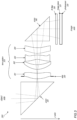
- Lenses 701 and 702 both have positive refractive power for light converging while splitting the spherical aberration contributions of each lens 701 and 702.
- Lens 703 has negative refractive power, and an aspheric shape to correct chromatic aberration and field curvature.
- Lens 704 works as an air space doublet with lens 703 to provide aberration correction.
- Lens 705 is a meniscus lens to correct field curvature and enable low F-number operation of the camera 700. In some embodiments, lens 705 may have low positive refractive power.
- the lens system 710 may be shifted along AX 2 independently of the two prisms 741 and 742 to allow refocusing of the lens system 710 between Infinity conjugate and Macro conjugate. In some embodiments, the lens system 710 may be shifted on one or more axes orthogonal to AX 2 to provide OIS functionality for the camera 700. In various embodiments, lens elements 701, 702, 703, 704, and/or 705 may be round/circular or rectangular, or some other shape. Note that in various embodiments, a lens system 710 may include more or fewer refractive lens elements, and the lens elements may be configured or arranged differently.
- one or both of the prisms 741 and 742 may be shifted independently of the lens system 710 along one or more axes by a mechanical actuator mechanism to facilitate autofocus functionality for the lens system 710.
- one or both of the prisms 741 and 742 may be translated with respect to the second axis (AX 2) independently of the lens system 710 and/or tilted with respect to the second axis (AX 2) independently of the lens system 742 by a mechanical actuator mechanism, for example to provide OIS functionality for the camera 710 or to shift the image formed at an image plane 721 at the photosensor 720.
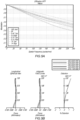
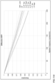
- FIG. 8A is a graph illustrating the modulation transfer function (MTF) for a lens system as illustrated in FIG. 7 at infinity conjugate.
- FIG. 8B shows longitudinal spherical aberration, astigmatic field curves, and distortion for a lens system as illustrated in FIG. 7 at infinity conjugate.
- MTF modulation transfer function
- FIG. 9A is a graph illustrating the modulation transfer function (MTF) for a lens system as illustrated in FIG. 7 at macro conjugate.
- FIG. 9B shows longitudinal spherical aberration, astigmatic field curves, and distortion for a lens system as illustrated in FIG. 7 at macro conjugate.
- MTF modulation transfer function
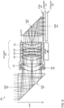
- the lens system 1010 may be shifted along the second axis (AX 2) independently of the two prisms 1041 and 1042 to allow refocusing of the lens system 1010 between Infinity conjugate and Macro conjugate. In some embodiments, the lens system 1010 may be shifted on one or more axes orthogonal to AX 2 to provide OIS functionality for the camera 1000. In various embodiments, lens elements 1001, 1002, 1003, and/or 1004 may be round/circular or rectangular, or some other shape. Note that in various embodiments, a lens system 1010 may include more or fewer refractive lens elements, and the lens elements may be configured or arranged differently.
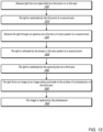
- FIG. 12 is a flowchart of a method for capturing images using embodiments of a camera as illustrated in FIGS. 1 through 11B , according to some embodiments.
- a first light folding element such as a prism on a first axis.
- the light is redirected by the first prism to a second axis.
- the light is received through an aperture at a first lens of a lens system on the second axis.
- the light is refracted by one or more lens elements of the lens system on the second axis to a second light folding element such as a prism.
- the light is redirected by the second light folding element to a third axis.
- the light forms an image at an image plane at or near the surface of a sensor module on the third axis.
- the image is captured by the photosensor.
- the lens system is independent of the first and second prisms.
- the camera may include an actuator component configured to move the lens system on one or more axes independently of the prisms to provide autofocus and/or OIS functionality for the camera.
- the components of the lens system referred to in FIG. 12 may be configured as illustrated in any of FIGS. 2 , 3 , 6 , 7 or 10 .
- FIGS. 2 , 3 , 6 , 7 or 10 the components of the lens system referred to in FIG. 12 may be configured as illustrated in any of FIGS. 2 , 3 , 6 , 7 or 10 .
- variations on the examples given in the Figures are possible while achieving similar optical results.
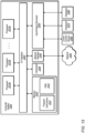
- FIG. 13 illustrates an example computing device, referred to as computer system 2000, that may include or host embodiments of a camera with a lens system as illustrated in FIGS. 1 through 12 .
- computer system 2000 may implement methods for controlling operations of the camera and/or for performing image processing of images captured with the camera.
- computer system 2000 may be any of various types of devices, including, but not limited to, a personal computer system, desktop computer, laptop, notebook, tablet or pad device, slate, or netbook computer, mainframe computer system, handheld computer, workstation, network computer, a camera, a set top box, a mobile device, a wireless phone, a smartphone, a consumer device, video game console, handheld video game device, application server, storage device, a television, a video recording device, a peripheral device such as a switch, modem, router, or in general any type of computing or electronic device.
- a personal computer system desktop computer, laptop, notebook, tablet or pad device, slate, or netbook computer
- mainframe computer system handheld computer
- workstation network computer
- a camera a set top box
- a mobile device a wireless phone
- smartphone a consumer device
- video game console handheld video game device
- application server storage device
- television a video recording device
- peripheral device such as a switch, modem, router, or in general any type of computing or electronic device.
- I/O interface 2030 may be configured to coordinate I/O traffic between processor 2010, system memory 2020, and any peripheral devices in the device, including network interface 2040 or other peripheral interfaces, such as input/output devices 2050.
- I/O interface 2030 may perform any necessary protocol, timing or other data transformations to convert data signals from one component (e.g., system memory 2020) into a format suitable for use by another component (e.g., processor 2010).
- I/O interface 2030 may include support for devices attached through various types of peripheral buses, such as a variant of the Peripheral Component Interconnect (PCI) bus standard or the Universal Serial Bus (USB) standard, for example.
- PCI Peripheral Component Interconnect
- USB Universal Serial Bus
- network interface 2040 may support communication via wired or wireless general data networks, such as any suitable type of Ethernet network, for example; via telecommunications/telephony networks such as analog voice networks or digital fiber communications networks; via storage area networks such as Fibre Channel SANs, or via any other suitable type of network and/or protocol.
- general data networks such as any suitable type of Ethernet network, for example; via telecommunications/telephony networks such as analog voice networks or digital fiber communications networks; via storage area networks such as Fibre Channel SANs, or via any other suitable type of network and/or protocol.
- Input/output devices 2050 may, in some embodiments, include one or more display terminals, keyboards, keypads, touchpads, scanning devices, voice or optical recognition devices, or any other devices suitable for entering or accessing data by computer system 2000. Multiple input/output devices 2050 may be present in computer system 2000 or may be distributed on various nodes of computer system 2000. In some embodiments, similar input/output devices may be separate from computer system 2000 and may interact with one or more nodes of computer system 2000 through a wired or wireless connection, such as over network interface 2040.
- instructions stored on a computer-accessible medium separate from computer system 2000 may be transmitted to computer system 2000 via transmission media or signals such as electrical, electromagnetic, or digital signals, conveyed via a communication medium such as a network and/or a wireless link.
- Various embodiments may further include receiving, sending or storing instructions and/or data implemented in accordance with the foregoing description upon a computer-accessible medium.
- a computer-accessible medium may include a non-transitory, computer-readable storage medium or memory medium such as magnetic or optical media, e.g., disk or DVD/CD-ROM, volatile or non-volatile media such as RAM (e.g. SDRAM, DDR, RDRAM, SRAM, etc.), ROM, etc.
- a computer-accessible medium may include transmission media or signals such as electrical, electromagnetic, or digital signals, conveyed via a communication medium such as network and/or a wireless link.
- the methods described herein may be implemented in software, hardware, or a combination thereof, in different embodiments.
- the order of the blocks of the methods may be changed, and various elements may be added, reordered, combined, omitted, modified, etc.
- Various modifications and changes may be made as would be obvious to a person skilled in the art having the benefit of this disclosure.
- the various embodiments described herein are meant to be illustrative and not limiting. Many variations, modifications, additions, and improvements are possible. Accordingly, plural instances may be provided for components described herein as a single instance. Boundaries between various components, operations and data stores are somewhat arbitrary, and particular operations are illustrated in the context of specific illustrative configurations.
Landscapes
- Physics & Mathematics (AREA)
- General Physics & Mathematics (AREA)
- Optics & Photonics (AREA)
- Engineering & Computer Science (AREA)
- General Engineering & Computer Science (AREA)
- Multimedia (AREA)
- Signal Processing (AREA)
- Lenses (AREA)
- Studio Devices (AREA)
Priority Applications (1)
| Application Number | Priority Date | Filing Date | Title |
|---|---|---|---|
| EP25208832.3A EP4657142A3 (de) | 2018-02-07 | 2019-02-04 | Gefaltete kamera |
Applications Claiming Priority (4)
| Application Number | Priority Date | Filing Date | Title |
|---|---|---|---|
| US201862627645P | 2018-02-07 | 2018-02-07 | |
| US16/264,463 US11061213B2 (en) | 2018-02-07 | 2019-01-31 | Folded camera |
| EP19705891.0A EP3735605A1 (de) | 2018-02-07 | 2019-02-04 | Gefaltete kamera |
| PCT/US2019/016523 WO2019156933A1 (en) | 2018-02-07 | 2019-02-04 | Folded camera |
Related Parent Applications (1)
| Application Number | Title | Priority Date | Filing Date |
|---|---|---|---|
| EP19705891.0A Division EP3735605A1 (de) | 2018-02-07 | 2019-02-04 | Gefaltete kamera |
Related Child Applications (2)
| Application Number | Title | Priority Date | Filing Date |
|---|---|---|---|
| EP25208832.3A Division EP4657142A3 (de) | 2018-02-07 | 2019-02-04 | Gefaltete kamera |
| EP25208832.3A Division-Into EP4657142A3 (de) | 2018-02-07 | 2019-02-04 | Gefaltete kamera |
Publications (2)
| Publication Number | Publication Date |
|---|---|
| EP4398019A1 true EP4398019A1 (de) | 2024-07-10 |
| EP4398019B1 EP4398019B1 (de) | 2025-12-31 |
Family
ID=67476602
Family Applications (3)
| Application Number | Title | Priority Date | Filing Date |
|---|---|---|---|
| EP24176600.5A Active EP4398019B1 (de) | 2018-02-07 | 2019-02-04 | Gefaltete kamera |
| EP19705891.0A Withdrawn EP3735605A1 (de) | 2018-02-07 | 2019-02-04 | Gefaltete kamera |
| EP25208832.3A Pending EP4657142A3 (de) | 2018-02-07 | 2019-02-04 | Gefaltete kamera |
Family Applications After (2)
| Application Number | Title | Priority Date | Filing Date |
|---|---|---|---|
| EP19705891.0A Withdrawn EP3735605A1 (de) | 2018-02-07 | 2019-02-04 | Gefaltete kamera |
| EP25208832.3A Pending EP4657142A3 (de) | 2018-02-07 | 2019-02-04 | Gefaltete kamera |
Country Status (4)
| Country | Link |
|---|---|
| US (3) | US11061213B2 (de) |
| EP (3) | EP4398019B1 (de) |
| CN (2) | CN115774317A (de) |
| WO (1) | WO2019156933A1 (de) |
Families Citing this family (36)
| Publication number | Priority date | Publication date | Assignee | Title |
|---|---|---|---|---|
| US10969652B2 (en) | 2018-01-10 | 2021-04-06 | Apple Inc. | Camera with folded optics having moveable lens |
| KR102770254B1 (ko) | 2018-01-26 | 2025-02-21 | 애플 인크. | 광학기기를 이동시키기 위한 액추에이터를 갖는 접이식 카메라 |
| US11061213B2 (en) | 2018-02-07 | 2021-07-13 | Apple Inc. | Folded camera |
| US11314147B1 (en) | 2018-05-31 | 2022-04-26 | Apple Inc. | Folded camera with actuator for moving optics |
| KR102776273B1 (ko) | 2018-09-14 | 2025-03-07 | 삼성전기주식회사 | 촬상 광학계 |
| US12585091B2 (en) | 2019-07-22 | 2026-03-24 | Apple Inc. | Camera including two light folding elements |
| US11714333B2 (en) | 2019-08-14 | 2023-08-01 | Guangzhou Luxvisions Innovations Technology Limited | Optical imaging apparatus capable of focusing |
| US11556047B2 (en) * | 2019-08-16 | 2023-01-17 | Tdk Taiwan Corp. | Optical member driving mechanism including matrix structure that corresponds to noise |
| KR102258604B1 (ko) * | 2019-09-10 | 2021-05-31 | 삼성전기주식회사 | 촬상 광학계 |
| TWI707188B (zh) * | 2019-09-18 | 2020-10-11 | 大立光電股份有限公司 | 相機模組與電子裝置 |
| US11243455B2 (en) | 2019-09-25 | 2022-02-08 | Apple Inc. | Camera with folded optics |
| CN213182169U (zh) | 2019-11-01 | 2021-05-11 | 台湾东电化股份有限公司 | 光学元件驱动机构 |
| CN111308672B (zh) * | 2020-04-10 | 2025-06-17 | 浙江舜宇光学有限公司 | 光学成像系统 |
| CN111505799B (zh) * | 2020-04-14 | 2025-04-22 | 浙江舜宇光学有限公司 | 光学成像透镜组 |
| KR102437800B1 (ko) | 2020-05-19 | 2022-08-30 | 삼성전기주식회사 | 카메라 모듈 |
| US11726304B2 (en) * | 2020-05-26 | 2023-08-15 | Apple Inc. | Folded optical systems |
| CN119583939A (zh) * | 2020-07-15 | 2025-03-07 | 核心光电有限公司 | 移动电子装置 |
| CN214586259U (zh) * | 2020-07-24 | 2021-11-02 | 台湾东电化股份有限公司 | 光学系统 |
| CN214474350U (zh) * | 2020-08-14 | 2021-10-22 | 台湾东电化股份有限公司 | 光学元件驱动机构 |
| CN112034596B (zh) * | 2020-09-24 | 2025-03-18 | 江西晶超光学有限公司 | 光学镜头、取像模组及电子装置 |
| CN114966919B (zh) * | 2021-02-27 | 2023-04-28 | 华为技术有限公司 | 长焦镜头、摄像头模组及电子设备 |
| KR102613873B1 (ko) * | 2021-04-30 | 2023-12-15 | 삼성전기주식회사 | 카메라 모듈 |
| DE102021112723B4 (de) | 2021-05-17 | 2025-10-30 | Schott Ag | Optisches System für ein Periskopkameramodul und Periskopkameramodul |
| US12192606B2 (en) * | 2021-10-07 | 2025-01-07 | Samsung Electro-Mechanics Co., Ltd. | Imaging lens system and camera module |
| EP4481460A4 (de) | 2022-05-26 | 2025-06-11 | Samsung Electronics Co., Ltd | Linsenanordnung und elektronische vorrichtung damit |
| US12574624B2 (en) | 2022-05-26 | 2026-03-10 | Samsung Electronics Co., Ltd. | Image-capturing device comprising refractive member and electronic device including the image-capturing device |
| US12177552B2 (en) | 2022-05-27 | 2024-12-24 | Samsung Electronics Co., Ltd. | Folded camera for reducing stray light and electronic device including the same |
| CN119301496A (zh) | 2022-05-27 | 2025-01-10 | 三星电子株式会社 | 镜头组件和包括该镜头组件的电子装置 |
| CN119213343A (zh) | 2022-05-27 | 2024-12-27 | 三星电子株式会社 | 透镜组件和包括该透镜组件的电子装置 |
| TW202429156A (zh) * | 2022-12-11 | 2024-07-16 | 以色列商核心光電有限公司 | 用於緊湊折疊式長焦相機的折射和混合鏡頭 |
| JP7767481B2 (ja) | 2023-02-24 | 2025-11-11 | キヤノン株式会社 | 光学系および撮像装置 |
| WO2024221180A1 (en) * | 2023-04-24 | 2024-10-31 | Huawei Technologies Co., Ltd. | Variable optical system and electronic device |
| TWI867520B (zh) | 2023-05-05 | 2024-12-21 | 大立光電股份有限公司 | 攝影系統透鏡組、取像裝置及電子裝置 |
| CN119071602A (zh) * | 2023-05-31 | 2024-12-03 | 北京小米移动软件有限公司 | 终端设备、镜头和摄像模组 |
| EP4699346A1 (de) * | 2023-08-11 | 2026-02-25 | Samsung Electronics Co., Ltd. | Vorrichtung und verfahren zur nahtlosen videoaufnahme während eines flex-state-übergangs |
| EP4716866A1 (de) * | 2023-09-19 | 2026-04-01 | Guangdong Oppo Mobile Telecommunications Corp., Ltd. | Abbildungslinsenanordnung, kameramodul und abbildungsvorrichtung |
Citations (2)
| Publication number | Priority date | Publication date | Assignee | Title |
|---|---|---|---|---|
| CN204422947U (zh) * | 2014-03-07 | 2015-06-24 | 苹果公司 | 照相机、折叠透镜系统及相关计算设备 |
| US9829684B2 (en) * | 2014-08-10 | 2017-11-28 | Corephotonics Ltd. | Zoom dual-aperture camera with folded lens |
Family Cites Families (57)
| Publication number | Priority date | Publication date | Assignee | Title |
|---|---|---|---|---|
| US2649022A (en) | 1950-02-17 | 1953-08-18 | Angenieux Pierre | Wide-angle photographic objective lens assembly |
| US3014080A (en) | 1955-04-04 | 1961-12-19 | Glidden Co | Preparation of menthenyl and menthanyl compounds |
| JP3979353B2 (ja) | 2002-08-02 | 2007-09-19 | セイコーエプソン株式会社 | 塗布方法 |
| JP3861815B2 (ja) * | 2003-01-17 | 2006-12-27 | コニカミノルタフォトイメージング株式会社 | 手振れ補正機能付きカメラ |
| JP2006154702A (ja) * | 2004-10-29 | 2006-06-15 | Konica Minolta Opto Inc | 変倍光学系、撮像レンズ装置及びデジタル機器 |
| JP4788953B2 (ja) | 2005-11-16 | 2011-10-05 | ソニー株式会社 | 撮像装置及びズームレンズ |
| CN101401023A (zh) | 2006-02-06 | 2009-04-01 | 诺基亚公司 | 使用装有万向节的棱镜的光学图像稳定器 |
| US7274518B1 (en) * | 2006-10-06 | 2007-09-25 | Largan Precision Co., Ltd. | Optical system for taking image |
| US8427761B2 (en) | 2009-03-10 | 2013-04-23 | Konica Minolta Opto, Inc. | Image pickup optical system, image pickup optical device, and digital equipment |
| JP5461981B2 (ja) | 2009-12-25 | 2014-04-02 | 日本電産サンキョー株式会社 | レンズ駆動装置 |
| JP5579555B2 (ja) * | 2010-09-24 | 2014-08-27 | Hoya株式会社 | 撮影光学系、及び撮影装置 |
| TWI418876B (zh) * | 2010-10-13 | 2013-12-11 | Largan Precision Co Ltd | 光學攝像系統 |
| US9172856B2 (en) | 2011-03-29 | 2015-10-27 | Microsoft Technology Licensing, Llc | Folded imaging path camera |
| US8670195B2 (en) | 2011-06-09 | 2014-03-11 | Panasonic Corporation | Lens actuator |
| JP2013125057A (ja) * | 2011-12-13 | 2013-06-24 | Foxsemicon Integrated Technology Inc | プロジェクションレンズ |
| TWI438476B (zh) * | 2012-01-12 | 2014-05-21 | Largan Precision Co Ltd | 取像系統 |
| TWI459351B (zh) | 2012-05-23 | 2014-11-01 | Macroblock Inc | 點矩陣發光二極體顯示裝置之驅動系統與驅動方法 |
| TWI570467B (zh) | 2012-07-06 | 2017-02-11 | 大立光電股份有限公司 | 光學影像拾取系統組 |
| JP5797627B2 (ja) | 2012-09-25 | 2015-10-21 | Hoya株式会社 | 撮像装置 |
| US9726862B2 (en) * | 2012-11-08 | 2017-08-08 | DynaOptics LTD, A Public Limited CO. | Lens assemblies and actuators for optical systems and methods therefor |
| JP6114049B2 (ja) | 2013-02-04 | 2017-04-12 | Hoya株式会社 | 撮像装置 |
| US9285566B2 (en) | 2013-08-08 | 2016-03-15 | Apple Inc. | Mirror tilt actuation |
| US9274311B2 (en) | 2014-01-13 | 2016-03-01 | Genius Electronic Optical Co., Ltd. | Compact narrow field of view lenses for mobile devices |
| JP6231416B2 (ja) | 2014-03-20 | 2017-11-15 | Hoya株式会社 | 撮像装置 |
| US9374516B2 (en) * | 2014-04-04 | 2016-06-21 | Qualcomm Incorporated | Auto-focus in low-profile folded optics multi-camera system |
| US9383550B2 (en) | 2014-04-04 | 2016-07-05 | Qualcomm Incorporated | Auto-focus in low-profile folded optics multi-camera system |
| US9549107B2 (en) | 2014-06-20 | 2017-01-17 | Qualcomm Incorporated | Autofocus for folded optic array cameras |
| US9386222B2 (en) | 2014-06-20 | 2016-07-05 | Qualcomm Incorporated | Multi-camera system using folded optics free from parallax artifacts |
| WO2016007754A1 (en) | 2014-07-10 | 2016-01-14 | Qtrco, Inc. | Method and system for controlling actuators |
| US20160044247A1 (en) | 2014-08-10 | 2016-02-11 | Corephotonics Ltd. | Zoom dual-aperture camera with folded lens |
| EP3492958B1 (de) | 2015-04-02 | 2022-03-30 | Corephotonics Ltd. | Doppelschwingspulenmotorstruktur in einer dualoptischen modulkamera |
| KR102114595B1 (ko) | 2015-05-28 | 2020-05-25 | 코어포토닉스 리미티드 | 이중-조리개 디지털 카메라의 광학식 손떨림 방지 및 자동-초점을 위한 양-방향성 강성 |
| CN107533272B (zh) | 2015-06-24 | 2020-09-11 | 核心光电有限公司 | 折叠式镜头相机的低剖面三轴致动器 |
| KR101717206B1 (ko) | 2015-08-05 | 2017-03-17 | 에이에이씨 어쿠스틱 테크놀로지스(심천)컴퍼니 리미티드 | 광학 손떨림 보정 가능한 카메라 렌즈 모듈 |
| KR102340778B1 (ko) | 2015-08-24 | 2021-12-20 | 엘지이노텍 주식회사 | 카메라 모듈 |
| KR102143730B1 (ko) | 2015-09-06 | 2020-08-12 | 코어포토닉스 리미티드 | 소형의 접이식 카메라의 롤 보정에 의한 자동 초점 및 광학식 손떨림 방지 |
| US10725313B2 (en) | 2015-11-20 | 2020-07-28 | Mitsumi Electric Co., Ltd. | Lens driving device, camera module and camera mounting device having shake-correcting function and auto-focusing function |
| KR20170075442A (ko) * | 2015-12-23 | 2017-07-03 | 삼성전자주식회사 | 촬상 장치 모듈, 이를 포함하는 사용자 단말 장치 및 촬상 장치 모듈의 작동 방법 |
| JP6358752B2 (ja) * | 2015-12-25 | 2018-07-18 | カンタツ株式会社 | 撮像レンズ |
| KR20170105236A (ko) | 2016-03-09 | 2017-09-19 | 엘지전자 주식회사 | 손떨림 보정 장치 |
| US9967547B2 (en) | 2016-06-08 | 2018-05-08 | Qualcomm Incorporated | Wafer level optics for folded optic passive depth sensing system |
| US9986223B2 (en) * | 2016-06-08 | 2018-05-29 | Qualcomm Incorporated | Folded optic passive depth sensing system |
| CN111367039B (zh) | 2016-07-07 | 2023-02-03 | 核心光电有限公司 | 用于折叠式光学装置的线性滚珠引导音圈电动机 |
| US10303042B2 (en) | 2016-07-12 | 2019-05-28 | Tdk Taiwan Corp. | Lens driving module |
| TWI616675B (zh) * | 2016-07-14 | 2018-03-01 | 大立光電股份有限公司 | 光學攝像系統組、取像裝置及電子裝置 |
| CN205942054U (zh) | 2016-08-24 | 2017-02-08 | 宁波舜宇光电信息有限公司 | 潜望式摄像模组 |
| TWI604218B (zh) | 2016-09-30 | 2017-11-01 | 大立光電股份有限公司 | 光學影像擷取系統鏡組、取像裝置及電子裝置 |
| TWI594037B (zh) | 2016-11-24 | 2017-08-01 | 大立光電股份有限公司 | 影像擷取鏡頭組、取像裝置及電子裝置 |
| US10534194B2 (en) * | 2017-02-17 | 2020-01-14 | Samsung Electro-Mechanics Co., Ltd. | Reflecting module for OIS and camera module including the same |
| KR102145896B1 (ko) | 2017-12-14 | 2020-08-19 | 엘지전자 주식회사 | 듀얼 프리즘 장치, 이를 구비하는 카메라 |
| US11029496B2 (en) | 2017-12-21 | 2021-06-08 | Apple Inc. | Folded lens system |
| US10969652B2 (en) | 2018-01-10 | 2021-04-06 | Apple Inc. | Camera with folded optics having moveable lens |
| EP4400892A3 (de) | 2018-01-25 | 2024-10-16 | Tdk Taiwan Corp. | Optisches system |
| KR102770254B1 (ko) | 2018-01-26 | 2025-02-21 | 애플 인크. | 광학기기를 이동시키기 위한 액추에이터를 갖는 접이식 카메라 |
| US11061213B2 (en) | 2018-02-07 | 2021-07-13 | Apple Inc. | Folded camera |
| US11314147B1 (en) | 2018-05-31 | 2022-04-26 | Apple Inc. | Folded camera with actuator for moving optics |
| US12585091B2 (en) | 2019-07-22 | 2026-03-24 | Apple Inc. | Camera including two light folding elements |
-
2019
- 2019-01-31 US US16/264,463 patent/US11061213B2/en active Active
- 2019-02-04 WO PCT/US2019/016523 patent/WO2019156933A1/en not_active Ceased
- 2019-02-04 CN CN202211400560.7A patent/CN115774317A/zh active Pending
- 2019-02-04 EP EP24176600.5A patent/EP4398019B1/de active Active
- 2019-02-04 EP EP19705891.0A patent/EP3735605A1/de not_active Withdrawn
- 2019-02-04 EP EP25208832.3A patent/EP4657142A3/de active Pending
- 2019-02-04 CN CN201980011847.0A patent/CN111712749B/zh active Active
-
2021
- 2021-07-09 US US17/371,732 patent/US11536936B2/en active Active
-
2022
- 2022-12-21 US US18/069,928 patent/US11754821B2/en active Active
Patent Citations (2)
| Publication number | Priority date | Publication date | Assignee | Title |
|---|---|---|---|---|
| CN204422947U (zh) * | 2014-03-07 | 2015-06-24 | 苹果公司 | 照相机、折叠透镜系统及相关计算设备 |
| US9829684B2 (en) * | 2014-08-10 | 2017-11-28 | Corephotonics Ltd. | Zoom dual-aperture camera with folded lens |
Also Published As
| Publication number | Publication date |
|---|---|
| CN111712749A (zh) | 2020-09-25 |
| EP4657142A3 (de) | 2026-01-28 |
| US11536936B2 (en) | 2022-12-27 |
| EP4398019B1 (de) | 2025-12-31 |
| US11754821B2 (en) | 2023-09-12 |
| US11061213B2 (en) | 2021-07-13 |
| WO2019156933A1 (en) | 2019-08-15 |
| EP3735605A1 (de) | 2020-11-11 |
| CN115774317A (zh) | 2023-03-10 |
| US20230119451A1 (en) | 2023-04-20 |
| US20190243112A1 (en) | 2019-08-08 |
| EP4657142A2 (de) | 2025-12-03 |
| CN111712749B (zh) | 2022-10-28 |
| US20210333529A1 (en) | 2021-10-28 |
Similar Documents
| Publication | Publication Date | Title |
|---|---|---|
| US11754821B2 (en) | Folded camera | |
| US12554106B2 (en) | Folded lens system | |
| US11635597B2 (en) | Folded lens system with three refractive lenses | |
| US11604337B2 (en) | Folded lens system with five refractive lenses | |
| EP3436862B1 (de) | Gefaltetes linsensystem mit vier refraktiven linsen | |
| US11988851B2 (en) | Lens system with optical actuator | |
| TWI830731B (zh) | 透鏡系統、照相機及成像系統 |
Legal Events
| Date | Code | Title | Description |
|---|---|---|---|
| PUAI | Public reference made under article 153(3) epc to a published international application that has entered the european phase |
Free format text: ORIGINAL CODE: 0009012 |
|
| STAA | Information on the status of an ep patent application or granted ep patent |
Free format text: STATUS: REQUEST FOR EXAMINATION WAS MADE |
|
| 17P | Request for examination filed |
Effective date: 20240517 |
|
| AC | Divisional application: reference to earlier application |
Ref document number: 3735605 Country of ref document: EP Kind code of ref document: P |
|
| AK | Designated contracting states |
Kind code of ref document: A1 Designated state(s): AL AT BE BG CH CY CZ DE DK EE ES FI FR GB GR HR HU IE IS IT LI LT LU LV MC MK MT NL NO PL PT RO RS SE SI SK SM TR |
|
| GRAP | Despatch of communication of intention to grant a patent |
Free format text: ORIGINAL CODE: EPIDOSNIGR1 |
|
| STAA | Information on the status of an ep patent application or granted ep patent |
Free format text: STATUS: GRANT OF PATENT IS INTENDED |
|
| INTG | Intention to grant announced |
Effective date: 20250305 |
|
| GRAJ | Information related to disapproval of communication of intention to grant by the applicant or resumption of examination proceedings by the epo deleted |
Free format text: ORIGINAL CODE: EPIDOSDIGR1 |
|
| STAA | Information on the status of an ep patent application or granted ep patent |
Free format text: STATUS: REQUEST FOR EXAMINATION WAS MADE |
|
| GRAP | Despatch of communication of intention to grant a patent |
Free format text: ORIGINAL CODE: EPIDOSNIGR1 |
|
| STAA | Information on the status of an ep patent application or granted ep patent |
Free format text: STATUS: GRANT OF PATENT IS INTENDED |
|
| INTC | Intention to grant announced (deleted) | ||
| INTG | Intention to grant announced |
Effective date: 20250520 |
|
| P01 | Opt-out of the competence of the unified patent court (upc) registered |
Free format text: CASE NUMBER: UPC_APP_9276_4398019/2025 Effective date: 20251007 |
|
| GRAS | Grant fee paid |
Free format text: ORIGINAL CODE: EPIDOSNIGR3 |
|
| GRAA | (expected) grant |
Free format text: ORIGINAL CODE: 0009210 |
|
| STAA | Information on the status of an ep patent application or granted ep patent |
Free format text: STATUS: THE PATENT HAS BEEN GRANTED |
|
| AC | Divisional application: reference to earlier application |
Ref document number: 3735605 Country of ref document: EP Kind code of ref document: P |
|
| AK | Designated contracting states |
Kind code of ref document: B1 Designated state(s): AL AT BE BG CH CY CZ DE DK EE ES FI FR GB GR HR HU IE IS IT LI LT LU LV MC MK MT NL NO PL PT RO RS SE SI SK SM TR |
|
| REG | Reference to a national code |
Ref country code: CH Ref legal event code: F10 Free format text: ST27 STATUS EVENT CODE: U-0-0-F10-F00 (AS PROVIDED BY THE NATIONAL OFFICE) Effective date: 20251231 Ref country code: GB Ref legal event code: FG4D |
|
| REG | Reference to a national code |
Ref country code: DE Ref legal event code: R096 Ref document number: 602019080036 Country of ref document: DE |
|
| REG | Reference to a national code |
Ref country code: IE Ref legal event code: FG4D |