EP4397882A1 - Disc brake and friction pad for vehicle - Google Patents
Disc brake and friction pad for vehicle Download PDFInfo
- Publication number
- EP4397882A1 EP4397882A1 EP22864556.0A EP22864556A EP4397882A1 EP 4397882 A1 EP4397882 A1 EP 4397882A1 EP 22864556 A EP22864556 A EP 22864556A EP 4397882 A1 EP4397882 A1 EP 4397882A1
- Authority
- EP
- European Patent Office
- Prior art keywords
- disc
- pad spring
- friction pads
- turn
- pad
- Prior art date
- Legal status (The legal status is an assumption and is not a legal conclusion. Google has not performed a legal analysis and makes no representation as to the accuracy of the status listed.)
- Pending
Links
Images





Classifications
-
- F—MECHANICAL ENGINEERING; LIGHTING; HEATING; WEAPONS; BLASTING
- F16—ENGINEERING ELEMENTS AND UNITS; GENERAL MEASURES FOR PRODUCING AND MAINTAINING EFFECTIVE FUNCTIONING OF MACHINES OR INSTALLATIONS; THERMAL INSULATION IN GENERAL
- F16D—COUPLINGS FOR TRANSMITTING ROTATION; CLUTCHES; BRAKES
- F16D55/00—Brakes with substantially-radial braking surfaces pressed together in axial direction, e.g. disc brakes
- F16D55/02—Brakes with substantially-radial braking surfaces pressed together in axial direction, e.g. disc brakes with axially-movable discs or pads pressed against axially-located rotating members
- F16D55/22—Brakes with substantially-radial braking surfaces pressed together in axial direction, e.g. disc brakes with axially-movable discs or pads pressed against axially-located rotating members by clamping an axially-located rotating disc between movable braking members, e.g. movable brake discs or brake pads
- F16D55/228—Brakes with substantially-radial braking surfaces pressed together in axial direction, e.g. disc brakes with axially-movable discs or pads pressed against axially-located rotating members by clamping an axially-located rotating disc between movable braking members, e.g. movable brake discs or brake pads with a separate actuating member for each side
-
- F—MECHANICAL ENGINEERING; LIGHTING; HEATING; WEAPONS; BLASTING
- F16—ENGINEERING ELEMENTS AND UNITS; GENERAL MEASURES FOR PRODUCING AND MAINTAINING EFFECTIVE FUNCTIONING OF MACHINES OR INSTALLATIONS; THERMAL INSULATION IN GENERAL
- F16D—COUPLINGS FOR TRANSMITTING ROTATION; CLUTCHES; BRAKES
- F16D65/00—Parts or details
- F16D65/02—Braking members; Mounting thereof
-
- F—MECHANICAL ENGINEERING; LIGHTING; HEATING; WEAPONS; BLASTING
- F16—ENGINEERING ELEMENTS AND UNITS; GENERAL MEASURES FOR PRODUCING AND MAINTAINING EFFECTIVE FUNCTIONING OF MACHINES OR INSTALLATIONS; THERMAL INSULATION IN GENERAL
- F16D—COUPLINGS FOR TRANSMITTING ROTATION; CLUTCHES; BRAKES
- F16D65/00—Parts or details
- F16D65/02—Braking members; Mounting thereof
- F16D65/04—Bands, shoes or pads; Pivots or supporting members therefor
- F16D65/092—Bands, shoes or pads; Pivots or supporting members therefor for axially-engaging brakes, e.g. disc brakes
- F16D65/095—Pivots or supporting members therefor
- F16D65/097—Resilient means interposed between pads and supporting members or other brake parts
- F16D65/0973—Resilient means interposed between pads and supporting members or other brake parts not subjected to brake forces
- F16D65/0974—Resilient means interposed between pads and supporting members or other brake parts not subjected to brake forces acting on or in the vicinity of the pad rim in a direction substantially transverse to the brake disc axis
- F16D65/0977—Springs made from sheet metal
Definitions
- the hanger pin disposed in a disc axial direction across an outer periphery of a disc rotor and suspending a pair of friction pads so as to be movable in a disc rotor axial direction, is provided in a ceiling opening portion formed in a bridge portion of a caliper body, the pad spring is arranged between the hanger pin and each of the friction pads, and the friction pads are urged to a disc radial inner side by an elastic piece of the pad spring to prevent rattling of the friction pads (see, for example, PTL 1).
- the pair of friction pads are arranged in a friction pad accommodating portion, the pad spring is arranged on a disc radial outer side of the friction pads, the hanger pin is inserted into each of the friction pads, the friction pads are assembled to the caliper body, the pad spring is assembled between the hanger pin and each of the friction pads, and the elastic piece of the pad spring abuts against each of the friction pads.
- an object of the invention is to provide a vehicular disc brake and a friction pad that can prevent a position of a pad spring from being displaced during assembly and improve an assembling property of the pad spring.
- the caliper body includes a friction pad accommodating portion that accommodates the friction pads, a locking groove that locks the pad spring is formed on a disc turn-in side wall of the friction pad accommodating portion when a vehicle is moving forward, the pad spring includes: a first elastic portion that abuts against a disc turn-in side of the friction pads when a vehicle is moving forward and that urges the friction pads to at least a disc radial inner side; and a second elastic portion that abuts against a disc turn-out side of the friction pads when a vehicle is moving forward and that urges the friction pads to a disc radial inner side and to a disc turn-out side, the first elastic portion is provided with the positioning piece and a locking piece inserted into the locking groove, and the locking groove is formed on a disc radial outer side than an accommodating groove of the disc rotor.
- the second elastic portion is formed to have a wide width in the disc axial direction and is provided with a second preventing portion that abuts against a wall portion of the ceiling opening portion to prevent a behavior of the pad spring, and an abutting surface of the wall portion against which the second preventing portion abuts is a casting surface.
- the friction pad including a lining attached to a back plate
- the back plate includes a suspension piece having a pin insertion hole in an intermediate portion in a longitudinal direction, and a pad spring abutting portion against which a positioning piece of a pad spring provided in the vehicular disc brake abuts is provided in parallel with the suspension piece when the friction pad is assembled to the vehicular disc brake.
- the friction pad further includes a recessed portion between the pad spring abutting portion and the suspension piece, the recessed portion serving as a space portion capable of accommodating the positioning piece.
- the pad spring when the friction pad and the pad spring are assembled to the caliper body, the pad spring is prevented from being displaced by abutting the positioning piece formed on the pad spring against the friction pad, and an assembling property of the pad spring can be improved.
- the pad spring since the locking groove that locks the pad spring is formed on the disc turn-in side wall of the friction pad accommodating portion when a vehicle is moving forward, the pad spring includes: the first elastic portion that abuts against the disc turn-in side of the friction pads when a vehicle is moving forward and that urges the friction pads to the disc radial inner side; and the second elastic portion that abuts against the disc turn-out side of the friction pads and that urges the friction pads to the disc radial inner side, the first elastic portion is provided with the locking piece inserted into the locking groove, and the locking groove is formed on the disc radial outer side than the accommodating groove of the disc rotor, when the disc turn-out side and the disc turn-in side of the pad spring are erroneously arranged and assembled in reverse, a set load is greatly increased, and thus, the assembly cannot be performed, and erroneous assembly of the pad spring can be prevented.
- the bridge portion includes the ceiling opening portion in the intermediate portion in the disc circumferential direction, and the first elastic portion of the pad spring is provided with the first preventing portion that abuts against the wall portion of the ceiling opening portion to prevent a behavior of the pad spring, unstable movement due to running vibration of the pad spring can be prevented. Further, since the abutting surface of the wall portion against which the first preventing portion abuts is a casting surface, processing cost can be reduced.
- the second elastic portion is provided with the second preventing portion that abuts against the wall portion of the ceiling opening portion to prevent a behavior of the pad spring, unstable movement due to the running vibration of the pad spring can be prevented. Further, since the abutting surface of the wall portion against which the second preventing portion abuts is a casting surface, the processing cost can be reduced.
- the friction pad used for the vehicular disc brake including the lining attached to the back plate
- the back plate includes the suspension piece having the pin insertion hole in the intermediate portion in the longitudinal direction
- the pad spring abutting portion against which the positioning piece of the pad spring provided in the vehicular disc brake abuts is provided in parallel with the suspension piece when the friction pad is assembled to the vehicular disc brake, so that the pad spring can be positioned by the friction pad.
- the recessed portion between the pad spring abutting portion and the suspension piece the recessed portion serving as a space portion capable of accommodating the positioning piece, the positioning piece can be easily accommodated, and a weight of the friction pad can be reduced.
- FIGS. 1 to 9 are views showing an embodiment of a vehicular disc brake and a friction pad of the invention, in which an arrow A indicates a rotation direction of a disc rotor that rotates integrally with wheels when a vehicle is moving forward, and a disc turn-out side and a disc turn-in side to be described later indicate those when the vehicle is moving forward.
- a vehicular disc brake 1 includes: a disc rotor 2 that rotates integrally with wheels (not shown) in an arrow A direction; a caliper body 3 attached to a vehicle body on one side of the disc rotor 2; and a pair of friction pads 5, 5 that are arranged inside the caliper body 3 so as to face each other with the disc rotor 2 interposed therebetween and are suspended by a hanger pin 4.
- a pad spring 6 that prevents rattling of the friction pads 5, 5 abuts against the friction pads 5, 5.
- the opposing-vehicle-body-side caliper half body 21 includes an action portion 21b in which cylinder portions 21a, 21a each having a cylinder hole 22 into which a piston 8 is inserted are arranged side by side in the disc circumferential direction, and a bridge portion half body 21c constituting substantially half of the bridge portion 3a
- the vehicle-body-side caliper half body 31 also includes an action portion 31b in which cylinder portions 31a, 31a each having a cylinder hole 32 into which the piston 8 is inserted are arranged side by side in the disc circumferential direction, and a bridge portion half body 31c constituting substantially half of the bridge portion 3a, similar to the opposing-vehicle-body-side caliper half body 21.
- an opposing-vehicle-body-side ceiling opening portion 21d and a vehicle-body-side ceiling opening portion 31d, which constitute substantially half of the ceiling opening portion 3b, are formed in the bridge portion half body 21c and the bridge portion half body 31c, respectively.
- a union hole 26 opening to a disc turn-out side surface 21f of the bridge portion half body 21c and the first working fluid introduction hole 24 is provided on the disc turn-out side of the bridge portion half body 21c, and a female screw portion 26a into which a union bolt (not shown) is screwed is formed on an opening side of the union hole 26.
- the action portion 21b of the opposing-vehicle-body-side caliper half body 21 includes the cylinder portions 21a, 21a having the cylinder holes 22, 22, a turn-out side body portion 21g extending from the cylinder portion 21a on the disc turn-out side to the disc turn-out side, and a turn-in side body portion 21j extending from the cylinder portion 21a on the disc turn-in side to the disc turn-in side.
- a pair of first reinforcing ribs 28, 28 are provided on the disc radial outer side and the disc radial inner side of an opposing disc rotor side surface 21h of the turn-out side body portion 21g, and the first reinforcing rib 28 on the disc radial outer side connects the cylinder portion 21a on the disc turn-out side and the large-diameter flange portion 27b on the disc radial outer side of the vehicle body attachment portion 27 on the disc turn-out side.
- first reinforcing rib 28 on the disc radial inner side connects the cylinder portion 21a on the disc turn-out side and the large-diameter flange portion 27b on the disc radial inner side of the vehicle body attachment portion 27 on the disc turn-out side.
- a first thinning portion 21i serving as a thin-walled portion is formed, by casting, on the opposing disc rotor side surface 21h between the first reinforcing ribs 28, 28.
- a pair of second reinforcing ribs 29, 29 are provided on the disc radial outer side and the disc radial inner side of the opposing disc rotor side surface 21h of the turn-in side body portion 21j, and the second reinforcing rib 29 on the disc radial outer side connects the cylinder portion 21a on the disc turn-in side and the large-diameter flange portion 27b on the disc radial outer side of the vehicle body attachment portion 27 on the disc turn-in side.
- the second reinforcing rib 29 on the disc radial inner side connects the cylinder portion 21a on the disc turn-in side and the large-diameter flange portion 27b on the disc radial inner side of the vehicle body attachment portion 27 on the disc turn-in side.
- a second thinning portion 21k serving as a thin-walled portion is formed, by casting, on the opposing disc rotor side surface 21h between the second reinforcing ribs 29, 29.
- an outer surface (opposing disc rotor side surface) OS1 of each first reinforcing rib 28 is formed to be gradually inclined toward a disc rotor side toward the disc turn-out side than an outer surface OS2 (opposing disc rotor side surface) of the cylinder portion 21a, and similarly, an outer surface (opposing disc rotor side surface) OS3 of each second reinforcing rib 29 is also formed to be gradually inclined toward the disc rotor side toward the disc turn-in side than the outer surface OS2 (opposing disc rotor side surface) of the cylinder portion 21a.
- a part of the bottom of the cylinder hole 32 on the disc turn-out side includes a fourth contouring machining portion 35a that allows the hydraulic pressure chamber 33 on the disc turn-out side and the second working fluid introduction hole 34 to communicate with each other by a contouring process, and a fifth contouring machining portion 35b that is contoured toward the hydraulic pressure chamber 33 on the disc turn-in side. Further, a part of the bottom of the cylinder hole 32 on the disc turn-in side includes a sixth contouring machining portion 35c that is contoured toward the fifth contouring machining portion 35b.
- the action portion 31b of the vehicle-body-side caliper half body 31 includes the cylinder portions 31a, 31a having the cylinder holes 32, 32, a turn-out side body portion 31g extending from the cylinder portion 31a on the disc turn-out side to the disc turn-out side, and a turn-in side body portion 31j extending from the cylinder portion 31a on the disc turn-in side to the disc turn-in side.
- the caliper body 3 is formed by bonding the opposing-vehicle-body-side caliper half body 21 and the vehicle-body-side caliper half body 31, which are formed as described above, to each other at the bridge portion 3a with the divided surfaces 21e, 31e abutting against each other, and coupling the opposing-vehicle-body-side caliper half body 21 and the vehicle-body-side caliper half body 31 with the coupling bolts 7, 7.
- the end surfaces 6k, 6k of the first elastic piece 6f and the end surfaces 6n, 6n of the second elastic portion 6e abut against the wall portions 3c, 3c on the opposing disc rotor side of the ceiling opening portion 3b, so that unstable movement due to running vibration of a pad spring can be prevented.
- abutting surfaces of the wall portions 3c, 3c against which the end surfaces 6k, 6k, 6n, 6n abut are casting surfaces, processing cost can be reduced.
- the end surfaces 6k, 6k, 6n, 6n including the first positioning piece 6g and the second positioning piece 6h and the bent portion 6m are formed in an arc shape, a contact area can be effectively obtained.
Landscapes
- Engineering & Computer Science (AREA)
- General Engineering & Computer Science (AREA)
- Mechanical Engineering (AREA)
- Braking Arrangements (AREA)
Abstract
Description
- The present invention relates to a vehicular disc brake, and more particularly to a vehicular disc brake and a friction pad in which rattling of the friction pad suspended by a hanger pin is prevented by a pad spring.
- In the related art, in a vehicular disc brake that prevents rattling of friction pads suspended by a hanger pin by a pad spring, the hanger pin, disposed in a disc axial direction across an outer periphery of a disc rotor and suspending a pair of friction pads so as to be movable in a disc rotor axial direction, is provided in a ceiling opening portion formed in a bridge portion of a caliper body, the pad spring is arranged between the hanger pin and each of the friction pads, and the friction pads are urged to a disc radial inner side by an elastic piece of the pad spring to prevent rattling of the friction pads (see, for example, PTL 1).
- PTL 1:
JP5171797B - In the vehicular disc brake of
PTL 1 described above, when the friction pads and the pad spring are assembled, the pair of friction pads are arranged in a friction pad accommodating portion, the pad spring is arranged on a disc radial outer side of the friction pads, the hanger pin is inserted into each of the friction pads, the friction pads are assembled to the caliper body, the pad spring is assembled between the hanger pin and each of the friction pads, and the elastic piece of the pad spring abuts against each of the friction pads. - However, when the hanger pin is inserted into each of the friction pads, and the pad spring is assembled between the hanger pin and each of the friction pads, the pad spring is displaced, and the pad spring cannot be assembled to a proper position in some cases.
- Therefore, an object of the invention is to provide a vehicular disc brake and a friction pad that can prevent a position of a pad spring from being displaced during assembly and improve an assembling property of the pad spring.
- In order to achieve the above object, a vehicular disc brake according to the invention includes: a caliper body including: an action portion arranged on a side portion of a disc rotor and having a cylinder hole into which a piston is to be inserted; and a bridge portion arranged across an outer periphery of the disc rotor; a pair of friction pads arranged on both side portions of the disc rotor; a hanger pin disposed in a disc axial direction across an outer periphery of the disc rotor and configured to suspend the pair of friction pads so as to be movable in a disc rotor axial direction; and a pad spring disposed between the hanger pin and the friction pads and configured to urge the friction pads to at least a disc radial inner side, in which the pad spring includes: a hanger pin abutting portion that abuts against an outer peripheral surface on a disc radial inner side of the hanger pin; an elastic portion that abuts against the pair of friction pads and urges the friction pads to a disc radial inner side; and a positioning piece that abuts against the friction pads to determine positioning of the pad spring when the friction pads and the pad spring are assembled to the caliper body.
- It is preferable that the caliper body includes a friction pad accommodating portion that accommodates the friction pads, a locking groove that locks the pad spring is formed on a disc turn-in side wall of the friction pad accommodating portion when a vehicle is moving forward, the pad spring includes: a first elastic portion that abuts against a disc turn-in side of the friction pads when a vehicle is moving forward and that urges the friction pads to at least a disc radial inner side; and a second elastic portion that abuts against a disc turn-out side of the friction pads when a vehicle is moving forward and that urges the friction pads to a disc radial inner side and to a disc turn-out side, the first elastic portion is provided with the positioning piece and a locking piece inserted into the locking groove, and the locking groove is formed on a disc radial outer side than an accommodating groove of the disc rotor.
- It is preferable that the bridge portion includes a ceiling opening portion in an intermediate portion in a disc circumferential direction, the first elastic portion is formed to have a wide width in the disc axial direction and is provided with a first preventing portion that abuts against a wall portion of the ceiling opening portion to prevent a behavior of the pad spring, and an abutting surface of the wall portion against which the first preventing portion abuts is a casting surface.
- It is preferable that the second elastic portion is formed to have a wide width in the disc axial direction and is provided with a second preventing portion that abuts against a wall portion of the ceiling opening portion to prevent a behavior of the pad spring, and an abutting surface of the wall portion against which the second preventing portion abuts is a casting surface.
- It is preferable that in a friction pad used for a vehicular disc brake, the friction pad including a lining attached to a back plate, the back plate includes a suspension piece having a pin insertion hole in an intermediate portion in a longitudinal direction, and a pad spring abutting portion against which a positioning piece of a pad spring provided in the vehicular disc brake abuts is provided in parallel with the suspension piece when the friction pad is assembled to the vehicular disc brake.
- It is preferable that the friction pad further includes a recessed portion between the pad spring abutting portion and the suspension piece, the recessed portion serving as a space portion capable of accommodating the positioning piece.
- According to the vehicular disc brake of the invention, when the friction pad and the pad spring are assembled to the caliper body, the pad spring is prevented from being displaced by abutting the positioning piece formed on the pad spring against the friction pad, and an assembling property of the pad spring can be improved.
- In addition, since the locking groove that locks the pad spring is formed on the disc turn-in side wall of the friction pad accommodating portion when a vehicle is moving forward, the pad spring includes: the first elastic portion that abuts against the disc turn-in side of the friction pads when a vehicle is moving forward and that urges the friction pads to the disc radial inner side; and the second elastic portion that abuts against the disc turn-out side of the friction pads and that urges the friction pads to the disc radial inner side, the first elastic portion is provided with the locking piece inserted into the locking groove, and the locking groove is formed on the disc radial outer side than the accommodating groove of the disc rotor, when the disc turn-out side and the disc turn-in side of the pad spring are erroneously arranged and assembled in reverse, a set load is greatly increased, and thus, the assembly cannot be performed, and erroneous assembly of the pad spring can be prevented.
- Since the bridge portion includes the ceiling opening portion in the intermediate portion in the disc circumferential direction, and the first elastic portion of the pad spring is provided with the first preventing portion that abuts against the wall portion of the ceiling opening portion to prevent a behavior of the pad spring, unstable movement due to running vibration of the pad spring can be prevented. Further, since the abutting surface of the wall portion against which the first preventing portion abuts is a casting surface, processing cost can be reduced.
- Since the second elastic portion is provided with the second preventing portion that abuts against the wall portion of the ceiling opening portion to prevent a behavior of the pad spring, unstable movement due to the running vibration of the pad spring can be prevented. Further, since the abutting surface of the wall portion against which the second preventing portion abuts is a casting surface, the processing cost can be reduced.
- In the friction pad used for the vehicular disc brake, the friction pad including the lining attached to the back plate, the back plate includes the suspension piece having the pin insertion hole in the intermediate portion in the longitudinal direction, and the pad spring abutting portion against which the positioning piece of the pad spring provided in the vehicular disc brake abuts is provided in parallel with the suspension piece when the friction pad is assembled to the vehicular disc brake, so that the pad spring can be positioned by the friction pad. In addition, by including the recessed portion between the pad spring abutting portion and the suspension piece, the recessed portion serving as a space portion capable of accommodating the positioning piece, the positioning piece can be easily accommodated, and a weight of the friction pad can be reduced.
-
- [
FIG. 1] FIG. 1 is a front view of a vehicular disc brake showing an embodiment of the invention. - [
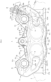
FIG. 2] FIG. 2 is a rear view of the same vehicular disc brake. - [
FIG. 3] FIG. 3 is a plan view of the same vehicular disc brake. - [
FIG. 4] FIG. 4 is a side view of the same vehicular disc brake. - [
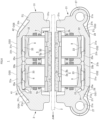
FIG. 5] FIG. 5 is a cross-sectional view taken along a line V-V inFIG. 4 . - [
FIG. 6] FIG. 6 is a cross-sectional view taken along a line VI-VI inFIG. 1 . - [
FIG. 7] FIG. 7 is a cross-sectional view taken along a line VII-VII inFIG. 1 . - [
FIG. 8] FIG. 8 is a view illustrating a case where friction pads and a pad spring are assembled to a caliper body. - [
FIG. 9] FIG. 9 is a perspective view of the pad spring. -
FIGS. 1 to 9 are views showing an embodiment of a vehicular disc brake and a friction pad of the invention, in which an arrow A indicates a rotation direction of a disc rotor that rotates integrally with wheels when a vehicle is moving forward, and a disc turn-out side and a disc turn-in side to be described later indicate those when the vehicle is moving forward. - A
vehicular disc brake 1 includes: adisc rotor 2 that rotates integrally with wheels (not shown) in an arrow A direction; acaliper body 3 attached to a vehicle body on one side of thedisc rotor 2; and a pair offriction pads caliper body 3 so as to face each other with thedisc rotor 2 interposed therebetween and are suspended by ahanger pin 4. Apad spring 6 that prevents rattling of thefriction pads friction pads - The
caliper body 3 is a divided type caliper body which is a radial mount type, is divided at abridge portion 3a straddling an outer peripheral side of thedisc rotor 2 and is formed by integrally coupling, with twocoupling bolts half body 21 and a vehicle-body-side caliperhalf body 31, . In addition, a rectangularceiling opening portion 3b includingwall portions disc rotor 2 and wall portions 3d, 3d parallel to a disc axis is formed in a central portion of thebridge portion 3a in a disc circumferential direction. - The opposing-vehicle-body-side caliper
half body 21 includes anaction portion 21b in whichcylinder portions cylinder hole 22 into which apiston 8 is inserted are arranged side by side in the disc circumferential direction, and a bridge portionhalf body 21c constituting substantially half of thebridge portion 3a, and the vehicle-body-side caliperhalf body 31 also includes anaction portion 31b in whichcylinder portions cylinder hole 32 into which thepiston 8 is inserted are arranged side by side in the disc circumferential direction, and a bridge portionhalf body 31c constituting substantially half of thebridge portion 3a, similar to the opposing-vehicle-body-side caliperhalf body 21. In addition, an opposing-vehicle-body-sideceiling opening portion 21d and a vehicle-body-sideceiling opening portion 31d, which constitute substantially half of theceiling opening portion 3b, are formed in the bridge portionhalf body 21c and the bridge portionhalf body 31c, respectively. - In the opposing-vehicle-body-side caliper
half body 21,hydraulic pressure chambers cylinder holes pistons fluid introduction hole 24 is drilled from a disc turn-out side of a dividedsurface 21e serving as a bonding surface of the bridge portionhalf body 21c toward thehydraulic pressure chamber 23 on the disc turn-out side, and a part of a bottom of thecylinder hole 22 on the disc turn-out side includes a firstcontouring machining portion 25a that allows thehydraulic pressure chamber 23 on the disc turn-out side and the first workingfluid introduction hole 24 to communicate with each other by a contouring process, and a secondcontouring machining portion 25b that is contoured toward thehydraulic pressure chamber 23 on the disc turn-in side. Further, a part of a bottom of thecylinder hole 22 on the disc turn-in side includes a thirdcontouring machining portion 25c that is contoured toward the secondcontouring machining portion 25b. The secondcontouring machining portion 25b and the thirdcontouring machining portion 25c communicate with each other, whereby the first workingfluid introduction hole 24, thehydraulic pressure chamber 23 on the disc turn-out side, and thehydraulic pressure chamber 23 on the disc turn-in side communicate with one another. - In addition, a
union hole 26 opening to a disc turn-outside surface 21f of the bridge portionhalf body 21c and the first workingfluid introduction hole 24 is provided on the disc turn-out side of the bridge portionhalf body 21c, and afemale screw portion 26a into which a union bolt (not shown) is screwed is formed on an opening side of theunion hole 26. In addition, radial mount type vehiclebody attachment portions half body 21, attachmentbolt insertion holes body attachment portions caliper body 3 is attached on a vehicle body by screwing attachment bolts inserted into the attachmentbolt insertion holes diameter flange portions body attachment portion 27, respectively. - The
action portion 21b of the opposing-vehicle-body-side caliperhalf body 21 includes thecylinder portions cylinder holes side body portion 21g extending from thecylinder portion 21a on the disc turn-out side to the disc turn-out side, and a turn-inside body portion 21j extending from thecylinder portion 21a on the disc turn-in side to the disc turn-in side. A pair offirst reinforcing ribs rotor side surface 21h of the turn-outside body portion 21g, and the first reinforcingrib 28 on the disc radial outer side connects thecylinder portion 21a on the disc turn-out side and the large-diameter flange portion 27b on the disc radial outer side of the vehiclebody attachment portion 27 on the disc turn-out side. In addition, the first reinforcingrib 28 on the disc radial inner side connects thecylinder portion 21a on the disc turn-out side and the large-diameter flange portion 27b on the disc radial inner side of the vehiclebody attachment portion 27 on the disc turn-out side. Further, a first thinningportion 21i serving as a thin-walled portion is formed, by casting, on the opposing discrotor side surface 21h between the first reinforcingribs - A pair of second
reinforcing ribs rotor side surface 21h of the turn-inside body portion 21j, and the second reinforcingrib 29 on the disc radial outer side connects thecylinder portion 21a on the disc turn-in side and the large-diameter flange portion 27b on the disc radial outer side of the vehiclebody attachment portion 27 on the disc turn-in side. In addition, the second reinforcingrib 29 on the disc radial inner side connects thecylinder portion 21a on the disc turn-in side and the large-diameter flange portion 27b on the disc radial inner side of the vehiclebody attachment portion 27 on the disc turn-in side. Further, a second thinningportion 21k serving as a thin-walled portion is formed, by casting, on the opposing discrotor side surface 21h between the second reinforcingribs - As shown in
FIGS. 1 and6 , an outer surface (opposing disc rotor side surface) OS1 of each first reinforcingrib 28 is formed to be gradually inclined toward a disc rotor side toward the disc turn-out side than an outer surface OS2 (opposing disc rotor side surface) of thecylinder portion 21a, and similarly, an outer surface (opposing disc rotor side surface) OS3 of eachsecond reinforcing rib 29 is also formed to be gradually inclined toward the disc rotor side toward the disc turn-in side than the outer surface OS2 (opposing disc rotor side surface) of thecylinder portion 21a. - An
attachment boss portion 30 having apin insertion hole 30a through which thehanger pin 4 is inserted is formed in the central portion in the disc circumferential direction on the disc radial outer side surface of theaction portion 21b. - In the vehicle-body-side caliper
half body 31,hydraulic pressure chambers cylinder holes pistons fluid introduction hole 34 is drilled from the disc turn-out side of a dividedsurface 31e serving as a bonding surface of the bridge portionhalf body 31c toward thehydraulic pressure chamber 33 on the disc turn-out side, and the first workingfluid introduction hole 24 and the second workingfluid introduction hole 34 communicate with each other by thedivided surfaces cylinder hole 32 on the disc turn-out side includes a fourthcontouring machining portion 35a that allows thehydraulic pressure chamber 33 on the disc turn-out side and the second workingfluid introduction hole 34 to communicate with each other by a contouring process, and a fifthcontouring machining portion 35b that is contoured toward thehydraulic pressure chamber 33 on the disc turn-in side. Further, a part of the bottom of thecylinder hole 32 on the disc turn-in side includes a sixthcontouring machining portion 35c that is contoured toward the fifthcontouring machining portion 35b. The fifthcontouring machining portion 35b and the sixthcontouring machining portion 35c communicate with each other, whereby the second workingfluid introduction hole 34, thehydraulic pressure chamber 33 on the disc turn-out side, and thehydraulic pressure chamber 33 on the disc turn-in side communicate with one another. - A
bleeder portion 37 having ableeder hole 36 opening to a disc radialouter side surface 31f and the second workingfluid introduction hole 34 is provided on the disc turn-out side of the bridgeportion half body 31c. - A
female screw portion 36a into which ableeder screw 39 is screwed is formed on an opening side of thebleeder hole 36, thebleeder screw 39 is provided with an air discharge hole (not shown) on an inner peripheral portion thereof and amale screw portion 39a on an outer peripheral portion thereof, which is screwed into thefemale screw portion 36a, and arubber bleeder cap 40 is covered to a tip end head portion thereof. - The
action portion 31b of the vehicle-body-sidecaliper half body 31 includes thecylinder portions side body portion 31g extending from thecylinder portion 31a on the disc turn-out side to the disc turn-out side, and a turn-inside body portion 31j extending from thecylinder portion 31a on the disc turn-in side to the disc turn-in side. A pair of third reinforcingribs rotor side surface 31h of the turn-outside body portion 31g, and the third reinforcingrib 41 on the disc radial outer side connects thecylinder portion 31a on the disc turn-out side and an end portion on the disc turn-out side of the turn-outside body portion 31g. In addition, the third reinforcingrib 41 on the disc radial inner side connects thecylinder portion 31a on the disc turn-out side and a disc turn-out side of the third reinforcingrib 41 on the disc radial outer side. Further, a third thinningportion 31i serving as a thin-walled portion is formed, by casting, on the opposing discrotor side surface 31h between the third reinforcingribs - Further, a pair of fourth reinforcing
ribs rotor side surface 31h of the turn-inside body portion 31j, and the fourth reinforcingrib 42 on the disc radial outer side connects thecylinder portion 31a on the disc turn-in side and an end portion on the disc turn-in side of the turn-inside body portion 31j. In addition, the fourth reinforcingrib 42 on the disc radial inner side connects thecylinder portion 31a on the disc turn-in side and a disc rotor turn-in side of the fourth reinforcingrib 42 on the disc radial outer side. Further, a fourth thinningportion 31k serving as a thin-walled portion is formed, by casting, on the opposing discrotor side surface 31h between the fourth reinforcingribs - As shown in
FIGS. 2 and6 , an outer surface (opposing disc rotor side surface) OS4 of each third reinforcingrib 41 is formed to be gradually inclined toward a disc rotor side toward the disc turn-out side than an outer surface OS5 (opposing disc rotor side surface) of thecylinder portion 31a, and similarly, an outer surface (opposing disc rotor side surface) OS6 of each fourth reinforcingrib 42 is also formed to be gradually inclined toward the disc rotor side toward the disc turn-in side than the outer surface OS5 (opposing disc rotor side surface) of thecylinder portion 31a. - An
attachment boss portion 43 having apin insertion hole 43a through which thehanger pin 4 is inserted is formed in the central portion in the disc circumferential direction on the disc radial outer side surface of theaction portion 31b so as to face theattachment boss portion 30 of the opposing-vehicle-body-sidecaliper half body 21. - The
caliper body 3 is formed by bonding the opposing-vehicle-body-sidecaliper half body 21 and the vehicle-body-sidecaliper half body 31, which are formed as described above, to each other at thebridge portion 3a with the dividedsurfaces caliper half body 21 and the vehicle-body-sidecaliper half body 31 with thecoupling bolts caliper half body 21 and the vehicle-body-sidecaliper half body 31, the first workingfluid introduction hole 24 and the second workingfluid introduction hole 34 communicate with each other, and accordingly, the first workingfluid introduction hole 24, the second workingfluid introduction hole 34, eachhydraulic pressure chamber 23 of the opposing-vehicle-body-sidecaliper half body 21, and eachhydraulic pressure chamber 33 of the vehicle-body-sidecaliper half body 31 communicate with each other, and thus, a fluid passage L1 is formed. In addition, since theunion hole 26 communicates with the first workingfluid introduction hole 24, a working fluid is supplied to the fluid passage L1 through theunion hole 26. Further, since thebleeder hole 36 communicates with the second workingfluid introduction hole 34, air mixed in the working fluid introduced into the fluid passage L1 is discharged to the outside through thebleeder screw 39. - A friction
pad accommodating portion 9 that accommodates thefriction pads 5 is formed in the turn-outside body portions side body portions side wall 9a of the frictionpad accommodating portion 9 formed in the turn-outside body portions side wall 9b of the frictionpad accommodating portion 9 formed in the turn-inside body portions friction pads groove 9c that locks thepad spring 6 is formed in the disc turn-inside wall 9b. - Each
friction pad 5 includes alining 5a which is in sliding contact with a side surface of thedisc rotor 2, and a metal backplate 5b to which thelining 5a is adhered. In theback plate 5b, asuspension piece 5e having a hangerpin insertion hole 5d through which thehanger pin 4 is inserted is provided to protrude from a central portion of a disc radialouter side surface 5c (an intermediate portion in a longitudinal direction of theback plate 5b), and a pair of first padspring abutting portions pad spring 6 abuts are provided adjacent to a disc turn-out side and a disc turn-in side of thesuspension piece 5e. Further, a pair of second padspring abutting portions outer side surface 5c, and thesuspension piece 5e, the first padspring abutting portions spring abutting portions outer side surface 5c, respectively. - The
hanger pin 4 is inserted into thepin insertion holes attachment boss portions ceiling opening portion 3b of thecaliper body 3, is inserted into the hangerpin insertion holes suspension pieces friction pad 5, and suspends thefriction pads friction pads pad accommodating portion 9. In addition, thepad spring 6 is provided over theback plate 5b and thehanger pin 4, and thefriction pads - The
pad spring 6 is formed by bending a single plate material punched into a predetermined shape, and includes: an arc-shaped hangerpin abutting portion 6a that abuts against an outer peripheral surface of thehanger pin 4 on the disc radial inner side; a firstelastic portion 6c that extends from the hangerpin abutting portion 6a to the disc turn-in side via a strip-shapedfirst spring piece 6b and abuts against the first padspring abutting portion 5f on the disc turn-in side of thefriction pads elastic portion 6e that extends from the hangerpin abutting portion 6a to the disc turn-out side via a strip-shapedsecond spring piece 6d and abuts against the second padspring abutting portion 5g on the disc turn-out side of thefriction pads - The first
elastic portion 6c includes: a firstelastic piece 6f that abuts against the first padspring abutting portion 5f on the disc turn-in side of thefriction pad 5 to elastically push thefriction pads first positioning pieces second positioning pieces friction pads pad spring 6 when thefriction pads pad spring 6 are assembled to thecaliper body 3; and alocking piece 6i locked in the lockinggroove 9c. - The
first positioning pieces second positioning pieces elastic piece 6f and bending the firstelastic piece 6f toward the disc radial inner side in an arc shape. As shown inFIG. 8 , when thefriction pads pad spring 6 are assembled to thecaliper body 3, thefirst positioning pieces portions suspension pieces spring abutting portions first positioning pieces portions first positioning pieces spring abutting portions second positioning pieces back plates 5b in the vicinity of the second padspring abutting portions - In addition, the
locking piece 6i protrudes to the disc turn-in side from a central portion in a disc axial direction of an end portion on a disc turn-in side of the firstelastic piece 6f, and atip end portion 6j thereof is inserted into the lockinggroove 9c. Further, the firstelastic piece 6f is formed to have a wide width in the disc axial direction, and endsurfaces wall portions ceiling opening portion 3b, respectively. - The second
elastic portion 6e is formed by bending the disc turn-out side into the disc radial outer side in an arc shape, and abuts abent portion 6m against the disc turn-inside surfaces spring abutting portions elastic portion 6e is formed to have a wide width in the disc axial direction, andend surfaces wall portions ceiling opening portion 3b. In addition, thewall portions ceiling opening portion 3b against which the end surfaces 6k, 6k, 6n, 6n abut are formed by a casting surface, respectively. In addition, a disc radialouter side surface 9d of the lockinggroove 9c is formed on the disc radial outer side than anaccommodating groove 3e of thedisc rotor 2 formed on a disc rotor side surface of thebridge portion 3a. - When the
friction pads pad spring 6, which are formed as described above, are assembled to thecaliper body 3, first, as shown inFIG. 8 , thefriction pads pad accommodating portion 9, thepad spring 6 is arranged on the disc radial outer side of thefriction pads tip end portion 6j of thelocking piece 6i is locked to the lockinggroove 9c. - At this time, the
first positioning pieces portions suspension pieces spring abutting portions spring abutting portions second positioning pieces spring abutting portions pad spring 6 is positioned with respect to thefriction pads - Next, the
hanger pin 4 is inserted throughout thepin insertion hole 30a of theattachment boss portion 30 of the opposing-vehicle-body-sidecaliper half body 21, thepin insertion hole 43a of theattachment boss portion 43 of the vehicle-body-sidecaliper half body 31, and the hangerpin insertion holes suspension pieces friction pads friction pads hanger pin 4 so as to be movable in the disc axial direction. In addition, an outer peripheral surface on a disc radial inner side of thehanger pin 4 abuts against the hangerpin abutting portion 6a of thepad spring 6 to press thepad spring 6, whereby thepad spring 6 is arranged at a set normal position shown inFIG. 5 . - In the
pad spring 6 arranged at the normal position, the outer peripheral surface on the disc radial inner side of thehanger pin 4 abuts against the hangerpin abutting portion 6a of thepad spring 6, and thetip end portion 6j of thelocking piece 6i is locked to the lockinggroove 9c. The firstelastic piece 6f of the firstelastic portions 6c abuts against disc radial outer side surfaces 5k, 5k of the first padspring abutting portions friction pads spring abutting portions friction pads bent portion 6m of the secondelastic portion 6e abuts against the disc turn-inside surfaces spring abutting portions friction pads elastic portion 6e elastically push thefriction pads wall portions ceiling opening portion 3b. - In the
caliper body 3 of the present embodiment, as described above, when thepad spring 6 is provided with thefirst positioning piece 6g and thesecond positioning piece 6h, and thefriction pads pad spring 6 are assembled to thecaliper body 3, thefirst positioning piece 6g and thesecond positioning piece 6h abut against thefriction pads pad spring 6 can be positioned with respect to thefriction pads pad spring 6 can be improved. - In addition, since the locking
groove 9c that locks thepad spring 6 is formed in the disc turn-inside wall 9b of the frictionpad accommodating portion 9 and the disc radialouter side surface 9d of the lockinggroove 9c is formed on the disc radial outer side than theaccommodating groove 3e of thedisc rotor 2, when the disc turn-out side and the disc turn-in side of thepad spring 6 are erroneously arranged and assembled in reverse, a set load is greatly increased, and thus, the assembly cannot be performed, and erroneous assembly of thepad spring 6 can be prevented. - In the
pad spring 6, the end surfaces 6k, 6k of the firstelastic piece 6f and theend surfaces elastic portion 6e abut against thewall portions ceiling opening portion 3b, so that unstable movement due to running vibration of a pad spring can be prevented. In addition, since abutting surfaces of thewall portions first positioning piece 6g and thesecond positioning piece 6h and thebent portion 6m are formed in an arc shape, a contact area can be effectively obtained. - In addition, since the
suspension piece 5e protruding to the disc radial outer side, the first padspring abutting portion 5f, and the second padspring abutting portion 5g are provided in parallel in the disc circumferential direction on the disc radialouter side surface 5c of theback plate 5b in thefriction pad 5, and the recessedportion 5h (space portion) into which thefirst positioning piece 6g can be inserted is provided between thesuspension piece 5e and the first padspring abutting portion 5f, thefirst positioning piece 6g can appropriately abut against theback plate 5b. - As in the above-described embodiment, the invention is not limited to being applied to a divided type caliper body, and can also be applied to a monocoque type caliper body. Further, the number of pistons and a configuration of a fluid passage are freely set. In addition, a vehicle body attachment portion formed in an opposing-vehicle-body-outer-side caliper half body may be an axial mount type vehicle body attachment portion having an attachment bolt insertion hole in a disc axial direction without any problem. Further, as in the present embodiment, the invention is not limited to being applied to a caliper body of a piston facing type disc brake, and can also be applied to a caliper body of a pin slide type disc brake in which an action portion including a piston and a reaction portion including a reaction force claw are provided on both side portions of a disc rotor.
- 1 vehicular disc brake; 2 disc rotor; 3 caliper body; 3a bridge portion; 3b ceiling opening portion; 3c, 3d wall portion; 3e accommodating groove; 4 hanger pin; 5 friction pad; 5a lining; 5b back plate; 5c disc radial outer side surface; 5d hanger pin insertion hole; 5e suspension piece; 5f first pad spring abutting portion; 5g second pad spring abutting portion; 5h recessed portion; 5i disc turn-out side surface; 5j disc turn-in side surface; 5k disc radial outer side surface; 6 pad spring; 6a hanger pin abutting portion; 6b first spring piece; 6c first elastic portion; 6d second spring piece; 6e second elastic portion; 6f first elastic piece; 6g first positioning piece; 6h second positioning piece; 6i locking piece; 6j tip end portion; 6m bent portion; 6k, 6n end surface; 7 coupling bolt; 8 piston; 9 friction pad accommodating portion; 9a disc turn-out side wall; 9b disc turn-in side wall; 9c locking groove; 21 opposing-vehicle-body-side caliper half body; 21a cylinder portion; 21b action portion; 21c bridge portion half body; 21d ceiling opening portion half body; 21e divided surface; 21f disc turn-out side surface; 21g turn-out side body portion; 21h opposing disc rotor side surface; 21i first thinning portion; 21j turn-in side body portion; 21k second thinning portion; 21m disc radial outer side surface; 22 cylinder hole; 23 hydraulic pressure chamber; 24 first working fluid introduction hole; 25a first contouring machining portion; 25b second contouring machining portion; 25c third contouring machining portion; 26 union hole; 26a female screw portion; 27 vehicle body attachment portion; 27a attachment bolt insertion hole; 28 first reinforcing rib; 29 second reinforcing rib; 30 attachment boss portion; 30a pin insertion hole; 31 vehicle-body-side caliper half body; 31a cylinder portion; 31b action portion; 31c bridge portion half body; 31d ceiling opening portion half body; 31e divided surface; 31f disc radial outer side surface; 31g turn-out side body portion; 31h opposing disc rotor side surface; 31i third thinning portion; 31j turn-in side body portion; 31k fourth thinning portion; 32 cylinder hole; 33 hydraulic pressure chamber; 34 second working fluid introduction hole; 35a fourth contouring machining portion; 35b fifth contouring machining portion; 35c sixth contouring machining portion; 36 bleeder hole; 36a female screw portion; 37 bleeder portion; 39 bleeder screw; 39a male screw portion; 40 bleeder cap; 41 third reinforcing rib; 42 fourth reinforcing rib; 43 attachment boss portion; 43a pin insertion hole
Claims (6)
- A vehicular disc brake, comprising:a caliper body including: an action portion arranged on a side portion of a disc rotor and having a cylinder hole into which a piston is to be inserted; and a bridge portion arranged across an outer periphery of the disc rotor;a pair of friction pads arranged on both side portions of the disc rotor;a hanger pin disposed in a disc axial direction across an outer periphery of the disc rotor and configured to suspend the pair of friction pads so as to be movable in a disc rotor axial direction; anda pad spring disposed between the hanger pin and the friction pads and configured to urge the friction pads to at least a disc radial inner side, whereinthe pad spring includes:a hanger pin abutting portion that abuts against an outer peripheral surface on a disc radial inner side of the hanger pin;an elastic portion that abuts against the pair of friction pads and urges the friction pads to a disc radial inner side; anda positioning piece that abuts against the friction pads to determine positioning of the pad spring when the friction pads and the pad spring are assembled to the caliper body.
- The vehicular disc brake according to claim 1, whereinthe caliper body includes a friction pad accommodating portion that accommodates the friction pads, a locking groove that locks the pad spring is formed on a disc turn-in side wall of the friction pad accommodating portion when a vehicle is moving forward,the pad spring includes: a first elastic portion that abuts against a disc turn-in side of the friction pads when a vehicle is moving forward and that urges the friction pads to at least a disc radial inner side; and a second elastic portion that abuts against a disc turn-out side of the friction pads when a vehicle is moving forward and that urges the friction pads to a disc radial inner side and to a disc turn-out side,the first elastic portion is provided with the positioning piece and a locking piece inserted into the locking groove, andthe locking groove is formed on a disc radial outer side than an accommodating groove of the disc rotor.
- The vehicular disc brake according to claim 1 or 2, whereinthe bridge portion includes a ceiling opening portion in an intermediate portion in a disc circumferential direction,the first elastic portion is formed to have a wide width in the disc axial direction and is provided with a first preventing portion that abuts against a wall portion of the ceiling opening portion to prevent a behavior of the pad spring, and an abutting surface of the wall portion against which the first preventing portion abuts is a casting surface.
- The vehicular disc brake according to claim 2 or 3, wherein
the second elastic portion is formed to have a wide width in the disc axial direction and is provided with a second preventing portion that abuts against a wall portion of the ceiling opening portion to prevent a behavior of the pad spring, and an abutting surface of the wall portion against which the second preventing portion abuts is a casting surface. - A friction pad used for a vehicular disc brake, the friction pad comprisinga lining attached to a back plate, whereinthe back plate includes a suspension piece having a pin insertion hole in an intermediate portion in a longitudinal direction, and a pad spring abutting portion against which a positioning piece of a pad spring provided in the vehicular disc brake abuts is provided in parallel with the suspension piece when the friction pad is assembled to the vehicular disc brake.
- The friction pad according to claim 5, further comprising
a recessed portion between the pad spring abutting portion and the suspension piece, the recessed portion serving as a space portion capable of accommodating the positioning piece.
Applications Claiming Priority (2)
| Application Number | Priority Date | Filing Date | Title |
|---|---|---|---|
| JP2021141945 | 2021-08-31 | ||
| PCT/JP2022/032571 WO2023032974A1 (en) | 2021-08-31 | 2022-08-30 | Disc brake and friction pad for vehicle |
Publications (2)
| Publication Number | Publication Date |
|---|---|
| EP4397882A1 true EP4397882A1 (en) | 2024-07-10 |
| EP4397882A4 EP4397882A4 (en) | 2025-09-10 |
Family
ID=85411253
Family Applications (1)
| Application Number | Title | Priority Date | Filing Date |
|---|---|---|---|
| EP22864556.0A Pending EP4397882A4 (en) | 2021-08-31 | 2022-08-30 | DISC BRAKE AND FRICTION PAD FOR A VEHICLE |
Country Status (5)
| Country | Link |
|---|---|
| EP (1) | EP4397882A4 (en) |
| JP (1) | JP7866563B2 (en) |
| CN (1) | CN117157471A (en) |
| BR (1) | BR112023021700A2 (en) |
| WO (1) | WO2023032974A1 (en) |
Family Cites Families (19)
| Publication number | Priority date | Publication date | Assignee | Title |
|---|---|---|---|---|
| DE1525385A1 (en) * | 1966-01-10 | 1970-02-05 | Teves Gmbh Alfred | Partly lined disc brake |
| JPS51101492U (en) * | 1975-02-13 | 1976-08-14 | ||
| JPS57179435A (en) * | 1981-04-27 | 1982-11-05 | Akebono Brake Ind Co Ltd | Holder spring used in integral knuckle type disk brake |
| FR2585794B1 (en) * | 1985-07-31 | 1987-11-13 | Bendix France | FRICTION SKATE ASSEMBLY HAVING AN NOISE SPRING FOR A DISC BRAKE |
| JP3257734B2 (en) * | 1993-11-17 | 2002-02-18 | トキコ株式会社 | Disc brake |
| DE4442795A1 (en) * | 1994-12-01 | 1996-06-05 | Teves Gmbh Alfred | Anti=rattle spring for brake discs |
| JPH09229110A (en) * | 1996-02-23 | 1997-09-02 | Nissin Kogyo Kk | Disc brakes for vehicles |
| JP2000145840A (en) * | 1998-11-06 | 2000-05-26 | Akebono Brake Ind Co Ltd | Prevention of clonk noise of disc brake |
| KR20030034336A (en) * | 2001-10-22 | 2003-05-09 | 주식회사 만도 | Disc brake for vehicle |
| JP4250108B2 (en) * | 2004-03-30 | 2009-04-08 | 日信工業株式会社 | Vehicle disc brake |
| FR2876427B1 (en) * | 2004-10-08 | 2008-03-14 | Bosch Gmbh Robert | FRICTION ELEMENT PROVIDED WITH RECALL MEANS AND DISC BRAKE COMPRISING SUCH A FRICTION ELEMENT |
| DE102005001482A1 (en) * | 2005-01-12 | 2006-07-20 | Gustav Magenwirth Gmbh & Co. Kg | Brake calliper and brake pad for a brake calliper |
| JP4668844B2 (en) * | 2006-05-29 | 2011-04-13 | 曙ブレーキ工業株式会社 | Opposite piston type disc brake |
| JP4857203B2 (en) * | 2007-06-26 | 2012-01-18 | 日立オートモティブシステムズ株式会社 | Disc brake |
| JP5607015B2 (en) * | 2011-11-30 | 2014-10-15 | 日信工業株式会社 | Vehicle disc brake |
| JP6686852B2 (en) * | 2016-11-18 | 2020-04-22 | 株式会社アドヴィックス | Disc brake with piston facing |
| US20190120308A1 (en) * | 2017-10-19 | 2019-04-25 | Hb Performance Systems, Inc. | Anti-rattle spring for brake caliper assembly |
| JP2020159369A (en) * | 2019-03-25 | 2020-10-01 | 日信工業株式会社 | Vehicle disc brakes |
| WO2021161642A1 (en) * | 2020-02-12 | 2021-08-19 | 日立Astemo株式会社 | Vehicle disc brake |
-
2022
- 2022-08-30 EP EP22864556.0A patent/EP4397882A4/en active Pending
- 2022-08-30 WO PCT/JP2022/032571 patent/WO2023032974A1/en not_active Ceased
- 2022-08-30 BR BR112023021700A patent/BR112023021700A2/en unknown
- 2022-08-30 CN CN202280026464.2A patent/CN117157471A/en active Pending
- 2022-08-30 JP JP2023545598A patent/JP7866563B2/en active Active
Also Published As
| Publication number | Publication date |
|---|---|
| EP4397882A4 (en) | 2025-09-10 |
| WO2023032974A1 (en) | 2023-03-09 |
| BR112023021700A2 (en) | 2023-12-19 |
| CN117157471A (en) | 2023-12-01 |
| JP7866563B2 (en) | 2026-05-27 |
| JPWO2023032974A1 (en) | 2023-03-09 |
Similar Documents
| Publication | Publication Date | Title |
|---|---|---|
| EP0851139B1 (en) | Disk brake | |
| US8439171B2 (en) | Vehicle disk brake | |
| EP0747608B1 (en) | Disc brake | |
| EP4105512B1 (en) | Vehicle disc brake | |
| EP3809009B1 (en) | Vehicular disc brake | |
| EP4253176B1 (en) | Caliper body of disc brake for vehicle | |
| US20060289253A1 (en) | Monoblock caliper housing for a disc brake assembly | |
| EP0087876B1 (en) | Disc brake caliper assembly | |
| EP4397883A1 (en) | Caliper body for vehicular disc brake | |
| US9353809B2 (en) | Vehicle disc brake | |
| JP2021173312A (en) | Floating type caliper | |
| US20110180354A1 (en) | Disc Brake | |
| EP3954921A1 (en) | Disc brake device | |
| CN117157471A (en) | Disc brake and friction pad for vehicle | |
| US20240344574A1 (en) | Return spring and disc brake | |
| JPH1163041A (en) | Caliper body of vehicle disc brake | |
| JP5603797B2 (en) | Vehicle disc brake | |
| EP4265935B1 (en) | Caliper body for vehicular disc brake | |
| JP7312797B2 (en) | Caliper body for vehicle disc brakes | |
| JP2020159369A (en) | Vehicle disc brakes | |
| JPH1130252A (en) | Divided caliper for disc brakes for vehicles | |
| WO2025013668A1 (en) | Disc brake | |
| JPH07180733A (en) | Disc brakes for vehicles | |
| JP2006002855A (en) | Floating caliper type disk brake | |
| JPH10238566A (en) | Disc brake |
Legal Events
| Date | Code | Title | Description |
|---|---|---|---|
| STAA | Information on the status of an ep patent application or granted ep patent |
Free format text: STATUS: THE INTERNATIONAL PUBLICATION HAS BEEN MADE |
|
| PUAI | Public reference made under article 153(3) epc to a published international application that has entered the european phase |
Free format text: ORIGINAL CODE: 0009012 |
|
| STAA | Information on the status of an ep patent application or granted ep patent |
Free format text: STATUS: REQUEST FOR EXAMINATION WAS MADE |
|
| 17P | Request for examination filed |
Effective date: 20231116 |
|
| AK | Designated contracting states |
Kind code of ref document: A1 Designated state(s): AL AT BE BG CH CY CZ DE DK EE ES FI FR GB GR HR HU IE IS IT LI LT LU LV MC MK MT NL NO PL PT RO RS SE SI SK SM TR |
|
| DAV | Request for validation of the european patent (deleted) | ||
| DAX | Request for extension of the european patent (deleted) | ||
| RAP3 | Party data changed (applicant data changed or rights of an application transferred) |
Owner name: ASTEMO, LTD. |
|
| A4 | Supplementary search report drawn up and despatched |
Effective date: 20250813 |
|
| RIC1 | Information provided on ipc code assigned before grant |
Ipc: F16D 65/02 20060101AFI20250807BHEP Ipc: F16D 65/095 20060101ALI20250807BHEP Ipc: F16D 65/097 20060101ALI20250807BHEP Ipc: F16D 55/225 20060101ALI20250807BHEP Ipc: F16D 55/228 20060101ALI20250807BHEP |