EP4397646A1 - System und verfahren zur umwandlung von co2 in kraftstoff - Google Patents
System und verfahren zur umwandlung von co2 in kraftstoff Download PDFInfo
- Publication number
- EP4397646A1 EP4397646A1 EP22864015.7A EP22864015A EP4397646A1 EP 4397646 A1 EP4397646 A1 EP 4397646A1 EP 22864015 A EP22864015 A EP 22864015A EP 4397646 A1 EP4397646 A1 EP 4397646A1
- Authority
- EP
- European Patent Office
- Prior art keywords
- heat storage
- heat
- water vapor
- reactor
- storage unit
- Prior art date
- Legal status (The legal status is an assumption and is not a legal conclusion. Google has not performed a legal analysis and makes no representation as to the accuracy of the status listed.)
- Pending
Links
Images


Classifications
-
- C—CHEMISTRY; METALLURGY
- C10—PETROLEUM, GAS OR COKE INDUSTRIES; TECHNICAL GASES CONTAINING CARBON MONOXIDE; FUELS; LUBRICANTS; PEAT
- C10L—FUELS NOT OTHERWISE PROVIDED FOR; NATURAL GAS; SYNTHETIC NATURAL GAS OBTAINED BY PROCESSES NOT COVERED BY SUBCLASSES C10G OR C10K; LIQUIFIED PETROLEUM GAS; USE OF ADDITIVES TO FUELS OR FIRES; FIRE-LIGHTERS
- C10L3/00—Gaseous fuels; Natural gas; Synthetic natural gas obtained by processes not covered by subclass C10G, C10K; Liquefied petroleum gas
- C10L3/06—Natural gas; Synthetic natural gas obtained by processes not covered by C10G, C10K3/02 or C10K3/04
- C10L3/08—Production of synthetic natural gas
-
- C—CHEMISTRY; METALLURGY
- C07—ORGANIC CHEMISTRY
- C07C—ACYCLIC OR CARBOCYCLIC COMPOUNDS
- C07C1/00—Preparation of hydrocarbons from one or more compounds, none of them being a hydrocarbon
- C07C1/02—Preparation of hydrocarbons from one or more compounds, none of them being a hydrocarbon from oxides of a carbon
- C07C1/12—Preparation of hydrocarbons from one or more compounds, none of them being a hydrocarbon from oxides of a carbon from carbon dioxide with hydrogen
-
- C—CHEMISTRY; METALLURGY
- C10—PETROLEUM, GAS OR COKE INDUSTRIES; TECHNICAL GASES CONTAINING CARBON MONOXIDE; FUELS; LUBRICANTS; PEAT
- C10G—CRACKING HYDROCARBON OILS; PRODUCTION OF LIQUID HYDROCARBON MIXTURES, e.g. BY DESTRUCTIVE HYDROGENATION, OLIGOMERISATION, POLYMERISATION; RECOVERY OF HYDROCARBON OILS FROM OIL-SHALE, OIL-SAND, OR GASES; REFINING MIXTURES MAINLY CONSISTING OF HYDROCARBONS; REFORMING OF NAPHTHA; MINERAL WAXES
- C10G2/00—Production of liquid hydrocarbon mixtures of undefined composition from oxides of carbon
- C10G2/50—Production of liquid hydrocarbon mixtures of undefined composition from oxides of carbon from carbon dioxide with hydrogen
-
- F—MECHANICAL ENGINEERING; LIGHTING; HEATING; WEAPONS; BLASTING
- F28—HEAT EXCHANGE IN GENERAL
- F28D—HEAT-EXCHANGE APPARATUS, NOT PROVIDED FOR IN ANOTHER SUBCLASS, IN WHICH THE HEAT-EXCHANGE MEDIA DO NOT COME INTO DIRECT CONTACT
- F28D20/00—Heat storage plants or apparatus in general; Regenerative heat-exchange apparatus not covered by groups F28D17/00 or F28D19/00
- F28D20/02—Heat storage plants or apparatus in general; Regenerative heat-exchange apparatus not covered by groups F28D17/00 or F28D19/00 using latent heat
-
- C—CHEMISTRY; METALLURGY
- C09—DYES; PAINTS; POLISHES; NATURAL RESINS; ADHESIVES; COMPOSITIONS NOT OTHERWISE PROVIDED FOR; APPLICATIONS OF MATERIALS NOT OTHERWISE PROVIDED FOR
- C09K—MATERIALS FOR MISCELLANEOUS APPLICATIONS, NOT PROVIDED FOR ELSEWHERE
- C09K5/00—Heat-transfer, heat-exchange or heat-storage materials, e.g. refrigerants; Materials for the production of heat or cold by chemical reactions other than by combustion
- C09K5/02—Materials undergoing a change of physical state when used
- C09K5/06—Materials undergoing a change of physical state when used the change of state being from liquid to solid or vice versa
- C09K5/063—Materials absorbing or liberating heat during crystallisation; Heat storage materials
-
- Y—GENERAL TAGGING OF NEW TECHNOLOGICAL DEVELOPMENTS; GENERAL TAGGING OF CROSS-SECTIONAL TECHNOLOGIES SPANNING OVER SEVERAL SECTIONS OF THE IPC; TECHNICAL SUBJECTS COVERED BY FORMER USPC CROSS-REFERENCE ART COLLECTIONS [XRACs] AND DIGESTS
- Y02—TECHNOLOGIES OR APPLICATIONS FOR MITIGATION OR ADAPTATION AGAINST CLIMATE CHANGE
- Y02E—REDUCTION OF GREENHOUSE GAS [GHG] EMISSIONS, RELATED TO ENERGY GENERATION, TRANSMISSION OR DISTRIBUTION
- Y02E60/00—Enabling technologies; Technologies with a potential or indirect contribution to GHG emissions mitigation
- Y02E60/30—Hydrogen technology
- Y02E60/36—Hydrogen production from non-carbon containing sources, e.g. by water electrolysis
-
- Y—GENERAL TAGGING OF NEW TECHNOLOGICAL DEVELOPMENTS; GENERAL TAGGING OF CROSS-SECTIONAL TECHNOLOGIES SPANNING OVER SEVERAL SECTIONS OF THE IPC; TECHNICAL SUBJECTS COVERED BY FORMER USPC CROSS-REFERENCE ART COLLECTIONS [XRACs] AND DIGESTS
- Y02—TECHNOLOGIES OR APPLICATIONS FOR MITIGATION OR ADAPTATION AGAINST CLIMATE CHANGE
- Y02P—CLIMATE CHANGE MITIGATION TECHNOLOGIES IN THE PRODUCTION OR PROCESSING OF GOODS
- Y02P20/00—Technologies relating to chemical industry
- Y02P20/10—Process efficiency
- Y02P20/133—Renewable energy sources, e.g. sunlight
Definitions
- the present invention relates to a system for reacting CO 2 with green hydrogen to convert the resultant into hydrocarbon.
- an object of the present invention is to provide a system and a method capable of stably producing a hydrocarbon with high efficiency from fluctuating renewable energy power by combining a hydrocarbonization reaction of CO 2 and water vapor electrolysis.
- a catalyst for converting the CO 2 105 into the hydrocarbon 107 by the hydrogen 106 is mounted.
- the structure of the hydrocarbon varies depending on the type of catalyst. For example, when Ni/Al 2 O 3 is used as the catalyst, methane is generated from hydrogen and CO 2 . CO may be used instead of CO 2 , or both of them may be used. CO 2 and CO may be collectively referred to as a reaction gas for a hydrocarbonization reaction or a carbon source gas.
- the heat storage unit 103 for the reactor 100 provides the amount of heat stored based on the reaction heat of the hydrocarbonization reaction to the environment of the hydrocarbonization reaction while the fluctuating electric power 111 decreases, and as a result, a temperature suitable for the hydrocarbonization reaction is maintained without limiting the supply amount of water.
- the heat storage unit 103A of the heat exchanger 104 also provides the amount of heat stored based on the heat of the exhaust gas 110 from the SOEC 102 before the fluctuating electric power 111 decreases to the water vapor 109 while the fluctuating electric power decreases, thereby suppressing the temperature decrease of the water vapor 109.
- the system of FIG. 1 provides a heat storage unit 103 including a heat storage material in at least one of the reactor 100 and the heat exchanger 104 as a region requiring temperature control.
- heat storage material there are various types of heat storage methods of the heat storage material, and there are sensible heat storage, latent heat storage, and chemical heat storage when the heat storage methods are roughly classified.
- Sensible heat storage utilizes specific heat of a substance
- latent heat storage utilizes transition heat (latent heat) associated with phase change and transition of a substance
- chemical heat storage utilizes endotherm and exotherm during chemical reaction (absorption, mixing, hydration).
- the latent heat storage material materials that can be selected are limited in a temperature range to be used. In particular, in a high temperature region of 250°C or higher, there are few options for organic substances, and therefore it is preferable to select an inorganic substance, particularly a salt compound or a metal material.
- examples of the metal material include lead having a melting point of 327.5°C as a simple metal, lead is not preferable because of toxicity. Since the melting point of the metal can be adjusted when the metal forms an alloy with another metal, the metal is preferably used as an alloy.
- examples of the metal material that can be utilized in a region requiring temperature control of the reactor 100 include alloys such as Zn, Al, Mg, Ag, Sn, and Cu. In a Mg-Zn-based alloy in which Mg having a melting point of 650°C and Zn having a melting point of 419°C are mixed at 49: 51 weight percent, the melting point is around 342°C, and therefore, the Mg-Zn-based alloy can be used as a heat storage material.
- the heat storage units 103 and 103A maintain the reactor 100 and the heat exchanger 104 at optimum temperatures by containing phase change materials having different melting points.
- the shape and form of the heat storage unit are not limited as long as heat can be transferred from a high-temperature fluid to a low-temperature fluid.
- FIG. 2 shows an example of a cross-sectional structure of the heat storage units 103 and 103A.
- the heat storage region 300 occupies a space sandwiched between a high-temperature fluid circulation unit 201 through which the high-temperature fluid flows and a low-temperature fluid circulation unit 202 through which the low-temperature fluid flows, and an internal space of the heat storage region 300 is filled with the above-described heat storage material.
- An amount of the heat storage material filled may be appropriately set in accordance with a target value or a design value of a heat storage capacity.
- the high-temperature fluid circulation unit 201 of the heat storage unit 103 circulates hydrocarbon 203 produced by reaction of hydrogen and carbon dioxide under a catalyst.
- the low-temperature fluid circulation unit 202 circulates water 204 (108 in FIG. 1 ), and converts the water into water vapor by heat from the high-temperature fluid via the heat storage region 300.
- high-temperature gas 203 (110 in FIG. 1 ) from the SOEC 102 flows through the high-temperature fluid circulation unit 201, and the water vapor 204 (109 in FIG. 1 ) flows through the low-temperature fluid circulation unit 202.
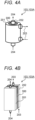
- FIG. 3B shows a form in which the high-temperature fluid circulation unit 201 is filled with the sphere 205.
- the low-temperature fluid circulation unit 202 may be filled with the sphere. Both the circulation units may be filled with the sphere.
- a measure for improving the specific surface area of the surface for example, an increase in surface roughness, a chemical etching treatment of the surface, addition of a fin or a honeycomb, or the like may be applied.
- FIG. 5 shows another form of the system of FIG. 1 .
- the system of FIG. 5 differs from the system of FIG. 1 in that the system of FIG. 5 includes, instead of the evaporator (101) of FIG. 1 , a cooler 101 that supplies a low-temperature oil (refrigerant) 402 to the reactor 100 and cools a reaction field of the hydrocarbonization reaction to deliver the high-temperature oil 403, and a heat exchanger 401 that performs heat exchange between the high-temperature oil 403 and the water 108 to deliver the water vapor 109.
- a circulation type refrigerant the same effect as that in FIG. 1 can be achieved.
- the SOEC 102 was operated at 750°C, and oxygen gas generated from the SOEC 102 was input to the heat exchanger 104.
- the temperature could be controlled at approximately 520°C.
- the temperature of the heat exchanger 104 was raised to about 600°C.
Landscapes
- Chemical & Material Sciences (AREA)
- Engineering & Computer Science (AREA)
- Oil, Petroleum & Natural Gas (AREA)
- Organic Chemistry (AREA)
- Chemical Kinetics & Catalysis (AREA)
- General Chemical & Material Sciences (AREA)
- Physics & Mathematics (AREA)
- Thermal Sciences (AREA)
- Mechanical Engineering (AREA)
- General Engineering & Computer Science (AREA)
- Production Of Liquid Hydrocarbon Mixture For Refining Petroleum (AREA)
- Organic Low-Molecular-Weight Compounds And Preparation Thereof (AREA)
- Physical Or Chemical Processes And Apparatus (AREA)
- Hydrogen, Water And Hydrids (AREA)
Applications Claiming Priority (2)
| Application Number | Priority Date | Filing Date | Title |
|---|---|---|---|
| JP2021142771A JP7680310B2 (ja) | 2021-09-01 | 2021-09-01 | Co2を燃料に変換するシステム、及び、その方法 |
| PCT/JP2022/024909 WO2023032427A1 (ja) | 2021-09-01 | 2022-06-22 | Co2を燃料に変換するシステム、及び、その方法 |
Publications (2)
| Publication Number | Publication Date |
|---|---|
| EP4397646A1 true EP4397646A1 (de) | 2024-07-10 |
| EP4397646A4 EP4397646A4 (de) | 2026-03-04 |
Family
ID=85412078
Family Applications (1)
| Application Number | Title | Priority Date | Filing Date |
|---|---|---|---|
| EP22864015.7A Pending EP4397646A4 (de) | 2021-09-01 | 2022-06-22 | System und verfahren zur umwandlung von co2 in kraftstoff |
Country Status (3)
| Country | Link |
|---|---|
| EP (1) | EP4397646A4 (de) |
| JP (1) | JP7680310B2 (de) |
| WO (1) | WO2023032427A1 (de) |
Families Citing this family (1)
| Publication number | Priority date | Publication date | Assignee | Title |
|---|---|---|---|---|
| WO2024203304A1 (ja) * | 2023-03-24 | 2024-10-03 | 国立大学法人北海道大学 | 反応熱利用システムおよび反応熱利用方法 |
Family Cites Families (6)
| Publication number | Priority date | Publication date | Assignee | Title |
|---|---|---|---|---|
| GB201202791D0 (en) | 2012-02-20 | 2012-04-04 | Simpson Robert | Methods and system for energy conversion and generation |
| AT518013B1 (de) | 2015-12-01 | 2018-11-15 | Christof International Man Gmbh | Anlage zur katalytischen methanisierung |
| JP6710646B2 (ja) | 2017-01-18 | 2020-06-17 | 株式会社東芝 | 高温蓄熱システム及び高温蓄熱方法 |
| JP2019108238A (ja) | 2017-12-18 | 2019-07-04 | 株式会社東芝 | 水素製造装置、燃料製造システム、水素製造方法、および燃料製造方法 |
| EP3739084A1 (de) * | 2019-05-14 | 2020-11-18 | Siemens Gamesa Renewable Energy GmbH & Co. KG | Wasserstoffherstellungssystem und verfahren zur herstellung von wasserstoff in einem wasserstoffherstellungssystem |
| JP2021080202A (ja) | 2019-11-19 | 2021-05-27 | 三菱パワー株式会社 | メタネーション反応装置 |
-
2021
- 2021-09-01 JP JP2021142771A patent/JP7680310B2/ja active Active
-
2022
- 2022-06-22 EP EP22864015.7A patent/EP4397646A4/de active Pending
- 2022-06-22 WO PCT/JP2022/024909 patent/WO2023032427A1/ja not_active Ceased
Also Published As
| Publication number | Publication date |
|---|---|
| WO2023032427A1 (ja) | 2023-03-09 |
| JP7680310B2 (ja) | 2025-05-20 |
| EP4397646A4 (de) | 2026-03-04 |
| JP2023035720A (ja) | 2023-03-13 |
Similar Documents
| Publication | Publication Date | Title |
|---|---|---|
| Prieto et al. | Review of technology: Thermochemical energy storage for concentrated solar power plants | |
| US20120122017A1 (en) | Heterogeneous hydrogen-catalyst power system | |
| JP2013501602A5 (de) | ||
| Dong et al. | Thermal optimisation of metal hydride reactors for thermal energy storage applications | |
| US20150060008A1 (en) | High-density, high-temperature thermal energy storage and retrieval | |
| CN107275722A (zh) | 电池或燃料电池系统 | |
| US10443954B1 (en) | High performance metal hydride based thermal energy storage systems for concentrating solar power | |
| EP2192083A1 (de) | Energieversorgungssystem | |
| CN105651091A (zh) | 传热增强型化学蓄热装置及应用该蓄热装置的蓄热系统 | |
| US20220349527A1 (en) | Hydrogen storage device | |
| EP4397646A1 (de) | System und verfahren zur umwandlung von co2 in kraftstoff | |
| JP2025069227A (ja) | 電源 | |
| JP2005100821A (ja) | 高温型燃料電池システム | |
| Potapov et al. | Magnesium hydride based hydrogen chemical source: Development and application perspectives | |
| TW202340664A (zh) | 能量利用系統及含碳材料之製造方法 | |
| Verga et al. | Scaling up effects of Mg hydride in a temperature and pressure-controlled hydrogen storage device | |
| JP2020033206A (ja) | 電力供給方法、電力供給システム | |
| US20240279526A1 (en) | High temperature thermochemical energy storage materials | |
| WO2017013152A1 (en) | System and method for storing and releasing heat | |
| Kim | Hydrogen production from solid sodium borohydride with hydrogen peroxide decomposition reaction | |
| GB2582607A (en) | Power supply | |
| JP2021048123A (ja) | 高温システムの熱管理のためのシステムおよび方法 | |
| US20240217812A1 (en) | Hydrogen release systems | |
| Lutz | Coupled metal hydride systems for energy storage | |
| Patekar et al. | Advancing Thermo-Chemical Energy Storage Systems for Enhanced Efficiency in Concentrated Solar Power Applications |
Legal Events
| Date | Code | Title | Description |
|---|---|---|---|
| STAA | Information on the status of an ep patent application or granted ep patent |
Free format text: STATUS: THE INTERNATIONAL PUBLICATION HAS BEEN MADE |
|
| PUAI | Public reference made under article 153(3) epc to a published international application that has entered the european phase |
Free format text: ORIGINAL CODE: 0009012 |
|
| STAA | Information on the status of an ep patent application or granted ep patent |
Free format text: STATUS: REQUEST FOR EXAMINATION WAS MADE |
|
| 17P | Request for examination filed |
Effective date: 20231211 |
|
| AK | Designated contracting states |
Kind code of ref document: A1 Designated state(s): AL AT BE BG CH CY CZ DE DK EE ES FI FR GB GR HR HU IE IS IT LI LT LU LV MC MK MT NL NO PL PT RO RS SE SI SK SM TR |
|
| DAV | Request for validation of the european patent (deleted) | ||
| DAX | Request for extension of the european patent (deleted) | ||
| A4 | Supplementary search report drawn up and despatched |
Effective date: 20260203 |
|
| RIC1 | Information provided on ipc code assigned before grant |
Ipc: C07C 1/12 20060101AFI20260128BHEP Ipc: C07C 9/04 20060101ALI20260128BHEP Ipc: C10L 3/08 20060101ALI20260128BHEP Ipc: C10G 2/00 20060101ALI20260128BHEP Ipc: F28D 20/00 20060101ALI20260128BHEP Ipc: F28D 20/02 20060101ALI20260128BHEP Ipc: C09K 5/06 20060101ALI20260128BHEP |