EP4397580A1 - Induction-type brake-alarming triggering device with self-adaptive structure - Google Patents
Induction-type brake-alarming triggering device with self-adaptive structure Download PDFInfo
- Publication number
- EP4397580A1 EP4397580A1 EP23203958.6A EP23203958A EP4397580A1 EP 4397580 A1 EP4397580 A1 EP 4397580A1 EP 23203958 A EP23203958 A EP 23203958A EP 4397580 A1 EP4397580 A1 EP 4397580A1
- Authority
- EP
- European Patent Office
- Prior art keywords
- induction
- brake
- self
- mounting
- brake handle
- Prior art date
- Legal status (The legal status is an assumption and is not a legal conclusion. Google has not performed a legal analysis and makes no representation as to the accuracy of the status listed.)
- Pending
Links
Images


Classifications
-
- B—PERFORMING OPERATIONS; TRANSPORTING
- B62—LAND VEHICLES FOR TRAVELLING OTHERWISE THAN ON RAILS
- B62J—CYCLE SADDLES OR SEATS; AUXILIARY DEVICES OR ACCESSORIES SPECIALLY ADAPTED TO CYCLES AND NOT OTHERWISE PROVIDED FOR, e.g. ARTICLE CARRIERS OR CYCLE PROTECTORS
- B62J6/00—Arrangement of optical signalling or lighting devices on cycles; Mounting or supporting thereof; Circuits therefor
- B62J6/04—Rear lights
- B62J6/045—Rear lights indicating braking
-
- B—PERFORMING OPERATIONS; TRANSPORTING
- B60—VEHICLES IN GENERAL
- B60T—VEHICLE BRAKE CONTROL SYSTEMS OR PARTS THEREOF; BRAKE CONTROL SYSTEMS OR PARTS THEREOF, IN GENERAL; ARRANGEMENT OF BRAKING ELEMENTS ON VEHICLES IN GENERAL; PORTABLE DEVICES FOR PREVENTING UNWANTED MOVEMENT OF VEHICLES; VEHICLE MODIFICATIONS TO FACILITATE COOLING OF BRAKES
- B60T7/00—Brake-action initiating means
- B60T7/02—Brake-action initiating means for personal initiation
- B60T7/08—Brake-action initiating means for personal initiation hand actuated
- B60T7/085—Brake-action initiating means for personal initiation hand actuated by electrical means, e.g. travel, force sensors
-
- B—PERFORMING OPERATIONS; TRANSPORTING
- B62—LAND VEHICLES FOR TRAVELLING OTHERWISE THAN ON RAILS
- B62J—CYCLE SADDLES OR SEATS; AUXILIARY DEVICES OR ACCESSORIES SPECIALLY ADAPTED TO CYCLES AND NOT OTHERWISE PROVIDED FOR, e.g. ARTICLE CARRIERS OR CYCLE PROTECTORS
- B62J45/00—Electrical equipment arrangements specially adapted for use as accessories on cycles, not otherwise provided for
- B62J45/40—Sensor arrangements; Mounting thereof
- B62J45/41—Sensor arrangements; Mounting thereof characterised by the type of sensor
-
- B—PERFORMING OPERATIONS; TRANSPORTING
- B60—VEHICLES IN GENERAL
- B60T—VEHICLE BRAKE CONTROL SYSTEMS OR PARTS THEREOF; BRAKE CONTROL SYSTEMS OR PARTS THEREOF, IN GENERAL; ARRANGEMENT OF BRAKING ELEMENTS ON VEHICLES IN GENERAL; PORTABLE DEVICES FOR PREVENTING UNWANTED MOVEMENT OF VEHICLES; VEHICLE MODIFICATIONS TO FACILITATE COOLING OF BRAKES
- B60T7/00—Brake-action initiating means
- B60T7/02—Brake-action initiating means for personal initiation
- B60T7/08—Brake-action initiating means for personal initiation hand actuated
- B60T7/10—Disposition of hand control
- B60T7/102—Disposition of hand control by means of a tilting lever
-
- B—PERFORMING OPERATIONS; TRANSPORTING
- B62—LAND VEHICLES FOR TRAVELLING OTHERWISE THAN ON RAILS
- B62J—CYCLE SADDLES OR SEATS; AUXILIARY DEVICES OR ACCESSORIES SPECIALLY ADAPTED TO CYCLES AND NOT OTHERWISE PROVIDED FOR, e.g. ARTICLE CARRIERS OR CYCLE PROTECTORS
- B62J45/00—Electrical equipment arrangements specially adapted for use as accessories on cycles, not otherwise provided for
- B62J45/40—Sensor arrangements; Mounting thereof
- B62J45/42—Sensor arrangements; Mounting thereof characterised by mounting
- B62J45/422—Sensor arrangements; Mounting thereof characterised by mounting on the handlebar
-
- B—PERFORMING OPERATIONS; TRANSPORTING
- B62—LAND VEHICLES FOR TRAVELLING OTHERWISE THAN ON RAILS
- B62J—CYCLE SADDLES OR SEATS; AUXILIARY DEVICES OR ACCESSORIES SPECIALLY ADAPTED TO CYCLES AND NOT OTHERWISE PROVIDED FOR, e.g. ARTICLE CARRIERS OR CYCLE PROTECTORS
- B62J6/00—Arrangement of optical signalling or lighting devices on cycles; Mounting or supporting thereof; Circuits therefor
- B62J6/05—Direction indicators
- B62J6/055—Electrical means, e.g. lamps
- B62J6/056—Electrical means, e.g. lamps characterised by control means
-
- B—PERFORMING OPERATIONS; TRANSPORTING
- B62—LAND VEHICLES FOR TRAVELLING OTHERWISE THAN ON RAILS
- B62K—CYCLES; CYCLE FRAMES; CYCLE STEERING DEVICES; RIDER-OPERATED TERMINAL CONTROLS SPECIALLY ADAPTED FOR CYCLES; CYCLE AXLE SUSPENSIONS; CYCLE SIDECARS, FORECARS, OR THE LIKE
- B62K23/00—Rider-operated controls specially adapted for cycles, i.e. means for initiating control operations, e.g. levers, grips
- B62K23/02—Rider-operated controls specially adapted for cycles, i.e. means for initiating control operations, e.g. levers, grips hand actuated
- B62K23/06—Levers
-
- B—PERFORMING OPERATIONS; TRANSPORTING
- B62—LAND VEHICLES FOR TRAVELLING OTHERWISE THAN ON RAILS
- B62L—BRAKES SPECIALLY ADAPTED FOR CYCLES
- B62L3/00—Brake-actuating mechanisms; Arrangements thereof
- B62L3/02—Brake-actuating mechanisms; Arrangements thereof for control by a hand lever
Definitions
- the present disclosure relates to a brake-alarming triggering device, and particularly relates to an induction-type brake-alarming triggering device with a self-adaptive structure.
- the brake is one of the important safeguards for the riding safety, and a good braking system can effectively improve the personal safety in riding.
- a braking-signal triggering device is installed at one end of the brake cable, detects the action of the brake cable, and accordingly automatically gives a braking signal to lighten the light.
- the braking-signal triggering device is usually required to contact the brake cable, which has the disadvantage of a complicated structure, and has a high failure rate.
- an acceleration sensor is used to detect the braking.
- erroneous determination easily happens due to a reduced speed in grade climbing of the vehicle, which has the disadvantage of a low accuracy.
- an induction-type brake-alarming triggering device with a self-adaptive structure wherein the device comprises a mounting base provided at a brake-lever base or a handle bar on a side of a brake handle, an power-supply module and a micro-controlling module are provided in the mounting base, and the micro-controlling module is wirelessly connected to an external warning light via a wireless-signal emitting module; and
- a reflection enhancing member in cooperation with the induction-type sensor is provided at the vehicle brake handle.
- an inner cavity of the mounting base is formed by a primary cavity horizontally provided and a secondary cavity that is integrally formed with and in communication with the primary cavity, the primary cavity and the secondary cavity cooperate to be of a ⁇ shape, and a quickly detachable pipe clamp is provided at a step formed by the cooperation between the primary cavity and the secondary cavity; and the first mounting through hole is located at a proximal end of a lower end of the secondary cavity and faces the brake handle.
- an axially regulating assembly for regulating an initial distance between the extending sleeve and the brake handle is provided between the first mounting through hole and the extending sleeve.
- the distance between the induction-type sensor and the brake handle is 0.8-2cm.
- the mounting base at the brake-lever base or the handle bar on a side of the brake handle by providing the mounting base at the brake-lever base or the handle bar on a side of the brake handle, and providing the induction-type sensor facing the brake handle at the self-adaptive elastic extending assembly, and by identifying the increased intensity of the light ray that is reflected back when the brake handle acts or the reduced duration of the reflecting-back of the light ray, the braking action is identified and in turn the braking signal is emitted. Further, by delicately installing the induction-type sensor at the self-adaptive elastic extending assembly, the self-adaptive elastic extending assembly can be closer to the brake handle.
- 1 mounting base; 1a: first mounting through hole; 1b: primary cavity; 1c: secondary cavity; 1d: quickly detachable pipe clamp; 1e: step through hole; 2: power-supply module; 3: micro-controlling module; 4: self-adaptive elastic extending assembly; 4a: extending sleeve; 4b: second mounting through hole; 4c: protecting lens; 4d: tensioning spring; 5: induction-type sensor; 6: reflection enhancing member; 7: rotary-knob base; 8: rotary-knob regulating cylinder; 8a: third mounting through hole; 9: regulating cylinder; 10: positioning screw; and 11: turn-light button.
- a guiding sleeve may be provided at the first mounting through hole, to increase the contact with the extending sleeve, to enable it to contract smoothly, which is easily envisaged by a person skilled in the art.
- a reflection enhancing member 6 in cooperation with the induction-type sensor 5 is provided at the vehicle brake handle. If the color of part of the brake lever is special, which is adverse for the corresponding induction-type sensor to reflect the light ray or affects the reflected light ray, then the reflection enhancing member may be used.
- the reflection enhancing member is preferably an elastic soft rubber cover facilitating light-ray reflection that can be directly nested to the brake handle and preferably has a color such as white and red.
- an inner cavity of the mounting base 1 is formed by a primary cavity 1b horizontally provided and a secondary cavity 1c that is integrally formed with and in communication with the primary cavity 1b, the primary cavity 1b and the secondary cavity 1c cooperate to be of a ⁇ shape, and a quickly detachable pipe clamp 1d is provided at the step formed by the cooperation between the primary cavity 1b and the secondary cavity 1c.
- the first mounting through hole 1a is located at the proximal end of the lower end of the secondary cavity 1c and faces the brake handle.
- FIGS. 5 and 6 show an induction-type brake-alarming triggering device with a self-adaptive structure according to the present disclosure. Its structure is substantially the same as that of the first embodiment, and differs in that an axially regulating assembly for regulating the initial distance between the extending sleeve 4a and the brake handle is provided between the first mounting through hole 1a and the extending sleeve 4a.
- the axially regulating assembly can perform pre-regulation to the distance between the induction-type sensor and the brake handle, and such a structure enables the triggering device to be generically useful in vehicles of different distances between the brake handle and the handle bar.
Landscapes
- Engineering & Computer Science (AREA)
- Mechanical Engineering (AREA)
- Transportation (AREA)
- Braking Arrangements (AREA)
- Valves And Accessory Devices For Braking Systems (AREA)
- Braking Elements And Transmission Devices (AREA)
- Motorcycle And Bicycle Frame (AREA)
- Steering Devices For Bicycles And Motorcycles (AREA)
Abstract
Description
- The present disclosure relates to a brake-alarming triggering device, and particularly relates to an induction-type brake-alarming triggering device with a self-adaptive structure.
- The brake is one of the important safeguards for the riding safety, and a good braking system can effectively improve the personal safety in riding. There are mainly two modes of controlling the brake light by smart braking systems currently worldwide:
- Firstly, a braking-signal triggering device is installed at one end of the brake cable, detects the action of the brake cable, and accordingly automatically gives a braking signal to lighten the light. In such a mode, the braking-signal triggering device is usually required to contact the brake cable, which has the disadvantage of a complicated structure, and has a high failure rate.
- Secondly, an acceleration sensor is used to detect the braking. However, erroneous determination easily happens due to a reduced speed in grade climbing of the vehicle, which has the disadvantage of a low accuracy.
- In view of the above problems, the inventor previously provides a triggering device that is installed between the brake handle and the handle bar and triggers by using a spring. Such a triggering mode cannot only automatically perform the light lightening triggering, but also the device is installed at the brake handle, and the light lightening is triggered merely when the brake handle acts, which has the advantages of accurate triggering, a simple structure and a low cost. However, it has been found in practical usage that, because the spring is exposed, it is susceptible to influence by an external force and thus be damaged.
- An object of the present disclosure is to, in view of the above-described disadvantages of the prior art, provide an induction-type brake-alarming triggering device with a self-adaptive structure that has a compact structure, accurate sensing and can perform self-adaptive stretching.
- The technical solutions of the present disclosure are realized as follows: an induction-type brake-alarming triggering device with a self-adaptive structure, wherein the device comprises a mounting base provided at a brake-lever base or a handle bar on a side of a brake handle, an power-supply module and a micro-controlling module are provided in the mounting base, and the micro-controlling module is wirelessly connected to an external warning light via a wireless-signal emitting module; and
- the power-supply module is connected to the micro-controlling module;
- wherein a first mounting through hole is provided on one side of the mounting base that faces the brake handle, a self-adaptive elastic extending assembly is provided at an opening part of the first mounting through hole, and an induction-type sensor facing the brake handle is provided at the self-adaptive elastic extending assembly;
- in an initial state, a distance between the induction-type sensor and the brake handle is 0.5-5cm, and when the brake handle is moved toward the handle bar to perform a braking action, an intensity of a light ray that is reflected back from the brake handle and received by the induction-type sensor is increased or a duration of the reflecting-back of the light ray is reduced, and the induction-type sensor sends a braking signal to the micro-controlling module; and
- when the brake handle touches a sensing terminal, the self-adaptive elastic extending assembly correspondingly contracts.
- Optionally, in the induction-type brake-alarming triggering device with a self-adaptive structure, a reflection enhancing member in cooperation with the induction-type sensor is provided at the vehicle brake handle.
- Optionally, in the induction-type brake-alarming triggering device with a self-adaptive structure, an inner cavity of the mounting base is formed by a primary cavity horizontally provided and a secondary cavity that is integrally formed with and in communication with the primary cavity, the primary cavity and the secondary cavity cooperate to be of a ┌ shape, and a quickly detachable pipe clamp is provided at a step formed by the cooperation between the primary cavity and the secondary cavity; and
the first mounting through hole is located at a proximal end of a lower end of the secondary cavity and faces the brake handle. - Optionally, in the induction-type brake-alarming triggering device with a self-adaptive structure, the self-adaptive elastic extending assembly comprises an extending sleeve nested inside the first mounting through hole and having one opened end, a second mounting through hole facing the brake handle is provided at a bottom inside the extending sleeve, a protecting lens is provided inside the second mounting through hole, and the induction-type sensor is located inside the extending sleeve; and
a tensioning spring is provided in an axial direction of the extending sleeve between the extending sleeve and an inner wall of the mounting base. - Optionally, in the induction-type brake-alarming triggering device with a self-adaptive structure, an axially regulating assembly for regulating an initial distance between the extending sleeve and the brake handle is provided between the first mounting through hole and the extending sleeve.
- Optionally, in the induction-type brake-alarming triggering device with a self-adaptive structure, the axially regulating assembly is formed by a rotary-knob base fixed inside the first mounting through hole and having an internal thread and a rotary-knob regulating cylinder thread-connected to the rotary-knob base and having one opened end, a third mounting through hole facing the brake handle is provided at a bottom inside the rotary-knob regulating cylinder, and the extending sleeve is slidably nested inside the third mounting through hole.
- Optionally, in the induction-type brake-alarming triggering device with a self-adaptive structure, the axially regulating assembly is formed by a regulating cylinder slidably nested inside the first mounting through hole and having one opened end and a positioning screw provided on the mounting base and in cooperation with the regulating cylinder; and
after a distance of the regulating cylinder has been regulated in place, the regulating cylinder is fixed by using the positioning screw. - Optionally, in the induction-type brake-alarming triggering device with a self-adaptive structure, in the initial state, the distance between the induction-type sensor and the brake handle is 0.8-2cm.
- In the present disclosure, by using the above-described structure, by providing the mounting base at the brake-lever base or the handle bar on a side of the brake handle, and providing the induction-type sensor facing the brake handle at the self-adaptive elastic extending assembly, and by identifying the increased intensity of the light ray that is reflected back when the brake handle acts or the reduced duration of the reflecting-back of the light ray, the braking action is identified and in turn the braking signal is emitted. Further, by delicately installing the induction-type sensor at the self-adaptive elastic extending assembly, the self-adaptive elastic extending assembly can be closer to the brake handle. It is obtained by experimentation that, when the distance between the induction-type sensor and the brake handle is controlled to be within 0.5-5cm, not only the interference of the external can be effectively reduced, but also the braking action can be further accurately detected. Furthermore, because no triggering connector exists between the mounting base and the brake handle, the device is not easily damaged by an external force, which can effectively prolong the service life.
- The present disclosure will be described in further detail below with reference to the embodiments in the drawings, which do not function to limit the present disclosure in any form.
-
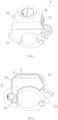
FIG. 1 is a schematic perspective structural diagram of the first embodiment of the present disclosure; -
FIG. 2 is a schematic internal structural diagram of the first embodiment of the present disclosure; -
FIG. 3 is a partially enlarged schematic diagram of the position A inFIG. 2 ; -
FIG. 4 is a schematic diagram of the usage state of the first embodiment of the present disclosure; -
FIG. 5 is a schematic internal structural diagram of the second embodiment of the present disclosure; -
FIG. 6 is a partially enlarged schematic diagram of the position B inFIG. 5 ; -
FIG. 7 is a schematic internal structural diagram of the third embodiment of the present disclosure; and -
FIG. 8 is a partially enlarged schematic diagram of the position C inFIG. 7 . - In the drawings: 1: mounting base; 1a: first mounting through hole; 1b: primary cavity; 1c: secondary cavity; 1d: quickly detachable pipe clamp; 1e: step through hole; 2: power-supply module; 3: micro-controlling module; 4: self-adaptive elastic extending assembly; 4a: extending sleeve; 4b: second mounting through hole; 4c: protecting lens; 4d: tensioning spring; 5: induction-type sensor; 6: reflection enhancing member; 7: rotary-knob base; 8: rotary-knob regulating cylinder; 8a: third mounting through hole; 9: regulating cylinder; 10: positioning screw; and 11: turn-light button.
- Referring to
FIGS. 1 to 4 , the induction-type brake-alarming triggering device with a self-adaptive structure according to the present disclosure comprises amounting base 1 provided at a brake-lever base or a handle bar on a side of a brake handle, an power-supply module 2 and amicro-controlling module 3 are provided in themounting base 1, themicro-controlling module 3 is wirelessly connected to an external warning light via a wireless-signal emitting module, the wireless-signal emitting module is integrated in the micro-controlling module, and the external warning light is correspondingly connected to a wireless-signal receiving module. The power-supply module 2 is connected to themicro-controlling module 3. - A first mounting through hole 1a is provided on the side of the
mounting base 1 that faces the brake handle, a self-adaptive elastic extendingassembly 4 is provided at an opening part of the first mounting through hole 1a, and an induction-type sensor 5 facing the brake handle is provided at the self-adaptive elastic extendingassembly 4. The induction-type sensor is preferably an infrared proximity sensor or a laser-reflection-type proximity transducer, and, certainly, may also be a magnetic induction sensor. The induction-type sensor may be installed within the mounting base in a manner well known in the art, and its installing mode is not what is claimed in the present disclosure, and is not discussed herein further. - In the initial state, the distance between the induction-
type sensor 5 and the brake handle is 0.5-5cm. It is obtained by experimentation that the optimum distance is 0.8-2cm, at which distance the effective detection rate of the induction-type sensor is above 95%. When the brake handle is moved toward the handle bar to perform a braking action, the intensity of a light ray that is reflected back from the brake handle and received by the induction-type sensor 5 is increased or the duration of the reflecting-back of the light ray is reduced, and the induction-type sensor sends a braking signal to themicro-controlling module 3. When the brake handle touches the sensing terminal where the induction-type sensor 5 is located, the self-adaptive elastic extendingassembly 4 correspondingly contracts. - By the effect of the self-adaptive elastic extending assembly, the distance between the induction-
type sensor 5 and the brake handle can be reduced to the largest extent, to prevent interference of the external. Furthermore, because the self-adaptive elastic extending assembly has the function of stretching, even in braking, when the brake handle touches the sensing terminal, the self-adaptive elastic extending assembly can contract to prevent affecting the braking while preventing colliding the sensing terminal. - In the present embodiment, the self-adaptive
elastic extending assembly 4 comprises an extendingsleeve 4a nested inside the first mounting through hole 1a and having one opened end, a second mounting throughhole 4b facing the brake handle is provided at the bottom inside the extendingsleeve 4a, a protectinglens 4c is provided inside the second mounting throughhole 4b, and the induction-type sensor 5 is located inside the extendingsleeve 4a. Atensioning spring 4d is provided in an axial direction of the extendingsleeve 4a between the extendingsleeve 4a and the inner wall of themounting base 1. - Certainly, in order to enable the extending sleeve to stretch smoothly, a guiding sleeve may be provided at the first mounting through hole, to increase the contact with the extending sleeve, to enable it to contract smoothly, which is easily envisaged by a person skilled in the art.
- Furthermore, a turn-
light button 11 connected to the micro-controlling module is provided at the surface of themounting base 1. When it is required to steer, a light lightening operation may be performed in advance, to improve the safety of the riding. - Preferably, a reflection enhancing member 6 in cooperation with the induction-
type sensor 5 is provided at the vehicle brake handle. If the color of part of the brake lever is special, which is adverse for the corresponding induction-type sensor to reflect the light ray or affects the reflected light ray, then the reflection enhancing member may be used. The reflection enhancing member is preferably an elastic soft rubber cover facilitating light-ray reflection that can be directly nested to the brake handle and preferably has a color such as white and red. - Further preferably, an inner cavity of the
mounting base 1 is formed by aprimary cavity 1b horizontally provided and asecondary cavity 1c that is integrally formed with and in communication with theprimary cavity 1b, theprimary cavity 1b and thesecondary cavity 1c cooperate to be of a ┌ shape, and a quicklydetachable pipe clamp 1d is provided at the step formed by the cooperation between theprimary cavity 1b and thesecondary cavity 1c. The first mounting through hole 1a is located at the proximal end of the lower end of thesecondary cavity 1c and faces the brake handle. Such a compact structure of the mounting base does not only facilitate the installation of the induction-type sensor, to facilitate it to face the brake handle, but also facilitates the induction-type sensor to be fixed to the brake-lever base or the handle bar. - In usage, it is merely required to install the mounting base on the brake-lever base or the handle bar, and cause the induction-type sensor on it to face the brake handle. When the brake handle performs a braking action, because of the movement of the brake handle, its distance from the induction-type sensor is reduced, the intensity of a light ray that is reflected back from the brake handle and received by the induction-
type sensor 5 is increased or the duration of the reflecting-back of the light ray is reduced, and the induction-type sensor sends a braking signal to themicro-controlling module 3. Subsequently, the micro-controlling module sends the braking signal via the wireless-signal emitting module to the external wireless-signal receiving module. The wireless-signal receiving module is formed by a controlling MCU, and a battery and a wireless-signal receiver that are connected to the controlling MCU, and the controlling MCU is connected to the turn light and a brake light. The wireless-signal receiver receives the braking signal or steering signal emitted by a wireless-signal emitting module, and the controlling MCU controls the corresponding turn light or brake light to be lightened. The wireless communication, the mode of the performance of the light lightening and the connection structures are in the prior art, are not what is claimed in the present disclosure, and are not discussed herein further. - Even in an emergency brake, when the brake handle is pressed very hard, to cause the brake handle to rotate by a largest angle, to cause the brake handle and the sensing terminal to contact, the extending sleeve can self-adaptively contract inwardly.
- Referring to
FIGS. 5 and 6, FIGS. 5 and 6 show an induction-type brake-alarming triggering device with a self-adaptive structure according to the present disclosure. Its structure is substantially the same as that of the first embodiment, and differs in that an axially regulating assembly for regulating the initial distance between the extendingsleeve 4a and the brake handle is provided between the first mounting through hole 1a and the extendingsleeve 4a. The axially regulating assembly can perform pre-regulation to the distance between the induction-type sensor and the brake handle, and such a structure enables the triggering device to be generically useful in vehicles of different distances between the brake handle and the handle bar. - In the present embodiment, the axially regulating assembly is formed by a rotary-
knob base 7 fixed inside the first mounting through hole 1a and having an internal thread and a rotary-knob regulating cylinder 8 thread-connected to the rotary-knob base 7 and having one opened end, a third mounting throughhole 8a facing the brake handle is provided at the bottom inside the rotary-knob regulating cylinder 8, and the extendingsleeve 4a is slidably nested inside the third mounting throughhole 8a. - The installing mode according to the present embodiment is the same as that of the first embodiment. After the installation has been completed, by regulating the distance between the induction-type sensor and the brake handle by using the axially regulating assembly according to the distance between the brake handle and the handle bar, the device can be used normally.
- Referring to
FIGS. 7 and 8, FIGS. 7 and 8 show an induction-type brake-alarming triggering device with a self-adaptive structure according to the present disclosure. Its structure is substantially the same as that of the first embodiment, and differs in that the axially regulating assembly is formed by a regulating cylinder 9 slidably nested inside the first mounting through hole 1a and having one opened end and apositioning screw 10 provided on the mountingbase 1 and in cooperation with the regulating cylinder 9. After the distance of the regulating cylinder 9 has been regulated in place, the regulating cylinder 9 is fixed by using thepositioning screw 10. - The advantage of such a structure is that, after the fine adjustment has been completed, the regulating cylinder may be fixed by using the first positioning screw, thereby preventing it from being influenced by an external force and thus accidently having an axial displacement, which affects the accuracy of the detection. Moreover, it has the advantages of a simple structure and a low cost.
- The above-described embodiments are preferable embodiments of the present disclosure, are merely intended to facilitate the description on the present disclosure, and are not intended to limit the present disclosure in any form. Any equivalent embodiments that are made by a person skilled in the art by partial alternation or modification to the technical contents disclosed by the present disclosure without departing from the scope of the technical features of the present disclosure fall within the scope of the technical features of the present disclosure.
Claims (8)
- An induction-type brake-alarming triggering device with a self-adaptive structure, wherein the device comprises a mounting base (1) provided at a brake-lever base or a handle bar on a side of a brake handle, an power-supply module (2) and a micro-controlling module (3) are provided in the mounting base (1), and the micro-controlling module (3) is wirelessly connected to an external warning light via a wireless-signal emitting module; andthe power-supply module (2) is connected to the micro-controlling module (3);characterised in that a first mounting through hole (1a) is provided on one side of the mounting base (1) that faces the brake handle, a self-adaptive elastic extending assembly (4) is provided at an opening part of the first mounting through hole (1a), and an induction-type sensor (5) facing the brake handle is provided at the self-adaptive elastic extending assembly (4);in an initial state, a distance between the induction-type sensor (5) and the brake handle is 0.5-5cm, and when the brake handle is moved toward the handle bar to perform a braking action, an intensity of a light ray that is reflected back from the brake handle and received by the induction-type sensor (5) is increased or a duration of the reflecting-back of the light ray is reduced, and the induction-type sensor (5) sends a braking signal to the micro-controlling module (3); andwhen the brake handle touches a sensing terminal, the self-adaptive elastic extending assembly (4) correspondingly contracts.
- The induction-type brake-alarming triggering device with a self-adaptive structure according to claim 1, wherein a reflection enhancing member (6) in cooperation with the induction-type sensor (5) is provided at the vehicle brake handle.
- The induction-type brake-alarming triggering device with a self-adaptive structure according to claim 1, wherein an inner cavity of the mounting base (1) is formed by a primary cavity (1b) horizontally provided and a secondary cavity (1c) that is integrally formed with and in communication with the primary cavity (1b), the primary cavity (1b) and the secondary cavity (1c) cooperate to be of a ┌ shape, and a quickly detachable pipe clamp (1d) is provided at a step formed by the cooperation between the primary cavity (1b) and the secondary cavity (1c); and
the first mounting through hole (1a) is located at a proximal end of a lower end of the secondary cavity (1c) and faces the brake handle. - The induction-type brake-alarming triggering device with a self-adaptive structure according to claim 1, wherein the self-adaptive elastic extending assembly (4) comprises an extending sleeve (4a) nested inside the first mounting through hole (1a) and having one opened end, a second mounting through hole (4b) facing the brake handle is provided at a bottom inside the extending sleeve (4a), a protecting lens (4c) is provided inside the second mounting through hole (4b), and the induction-type sensor (5) is located inside the extending sleeve (4a); and
a tensioning spring (4d) is provided in an axial direction of the extending sleeve (4a) between the extending sleeve (4a) and an inner wall of the mounting base (1). - The induction-type brake-alarming triggering device with a self-adaptive structure according to claim 4, wherein an axially regulating assembly for regulating an initial distance between the extending sleeve (4a) and the brake handle is provided between the first mounting through hole (1a) and the extending sleeve (4a).
- The induction-type brake-alarming triggering device with a self-adaptive structure according to claim 5, wherein the axially regulating assembly is formed by a rotary-knob base (7) fixed inside the first mounting through hole (1a) and having an internal thread and a rotary-knob regulating cylinder (8) thread-connected to the rotary-knob base (7) and having one opened end, a third mounting through hole (8a) facing the brake handle is provided at a bottom inside the rotary-knob regulating cylinder (8), and the extending sleeve (4a) is slidably nested inside the third mounting through hole (8a).
- The induction-type brake-alarming triggering device with a self-adaptive structure according to claim 5, wherein the axially regulating assembly is formed by a regulating cylinder (9) slidably nested inside the first mounting through hole (1a) and having one opened end and a positioning screw (10) provided on the mounting base (1) and in cooperation with the regulating cylinder (9); and
after a distance of the regulating cylinder (9) has been regulated in place, the regulating cylinder (9) is fixed by using the positioning screw (10). - The induction-type brake-alarming triggering device with a self-adaptive structure according to claim 1, wherein in the initial state, the distance between the induction-type sensor (5) and the brake handle is 0.8-2cm.
Applications Claiming Priority (1)
| Application Number | Priority Date | Filing Date | Title |
|---|---|---|---|
| CN202211548169.1A CN115973315B (en) | 2022-12-05 | 2022-12-05 | Induction type brake warning trigger device with self-adaptation structure |
Publications (1)
| Publication Number | Publication Date |
|---|---|
| EP4397580A1 true EP4397580A1 (en) | 2024-07-10 |
Family
ID=85974899
Family Applications (1)
| Application Number | Title | Priority Date | Filing Date |
|---|---|---|---|
| EP23203958.6A Pending EP4397580A1 (en) | 2022-12-05 | 2023-11-13 | Induction-type brake-alarming triggering device with self-adaptive structure |
Country Status (6)
| Country | Link |
|---|---|
| US (1) | US20240182003A1 (en) |
| EP (1) | EP4397580A1 (en) |
| JP (1) | JP7498987B1 (en) |
| KR (1) | KR102818416B1 (en) |
| CN (1) | CN115973315B (en) |
| TW (1) | TW202423762A (en) |
Citations (2)
| Publication number | Priority date | Publication date | Assignee | Title |
|---|---|---|---|---|
| CN2376419Y (en) * | 1999-06-27 | 2000-05-03 | 潘余明 | Hand brake bar with induction circuit switch |
| CN204775781U (en) * | 2015-06-18 | 2015-11-18 | 天津雅迪实业有限公司 | Electromagnetism brake execution systems |
Family Cites Families (10)
| Publication number | Priority date | Publication date | Assignee | Title |
|---|---|---|---|---|
| JP3101270U (en) * | 2003-10-29 | 2004-06-10 | 志安 許 | Bicycle brake lamp control device |
| JP5218658B2 (en) | 2009-07-09 | 2013-06-26 | トヨタ自動車株式会社 | Braking / driving force control device |
| TWM372312U (en) * | 2009-09-04 | 2010-01-11 | yu-xiong Fan | Brake sensing device of bicycle |
| CN201512049U (en) * | 2009-09-16 | 2010-06-23 | 李清彰 | Wireless Brake Light Device |
| KR20120007766A (en) * | 2010-07-15 | 2012-01-25 | 박도형 | Directional Indicator for Motorcycles Using Brake Handles |
| KR101564163B1 (en) * | 2014-02-13 | 2015-10-28 | 김성권 | Brake lever for bicycle |
| WO2021019980A1 (en) * | 2019-07-31 | 2021-02-04 | 日信工業株式会社 | Operation amount detection device for bar handle vehicle |
| CN110282057B (en) * | 2019-08-07 | 2024-03-19 | 梅州市明眸电子科技有限公司 | Brake warning device mounted on bicycle or motorcycle handle |
| CN215944800U (en) * | 2021-11-08 | 2022-03-04 | 深特佳(广东)科技有限公司 | Bicycle wireless control brake lamp system |
| CN218877469U (en) * | 2022-12-05 | 2023-04-18 | 梅州市明眸电子科技有限公司 | Induction type brake warning trigger device for vehicle brake handle |
-
2022
- 2022-12-05 CN CN202211548169.1A patent/CN115973315B/en active Active
-
2023
- 2023-03-31 JP JP2023057107A patent/JP7498987B1/en active Active
- 2023-03-31 US US18/193,914 patent/US20240182003A1/en not_active Abandoned
- 2023-03-31 KR KR1020230042744A patent/KR102818416B1/en active Active
- 2023-06-05 TW TW112120897A patent/TW202423762A/en unknown
- 2023-11-13 EP EP23203958.6A patent/EP4397580A1/en active Pending
Patent Citations (2)
| Publication number | Priority date | Publication date | Assignee | Title |
|---|---|---|---|---|
| CN2376419Y (en) * | 1999-06-27 | 2000-05-03 | 潘余明 | Hand brake bar with induction circuit switch |
| CN204775781U (en) * | 2015-06-18 | 2015-11-18 | 天津雅迪实业有限公司 | Electromagnetism brake execution systems |
Non-Patent Citations (1)
| Title |
|---|
| WIKIPEDIA: "Inductive sensor", 7 May 2024 (2024-05-07), pages 1 - 1, XP093160209, Retrieved from the Internet <URL:https://en.wikipedia.org/wiki/Inductive_sensor#:~:text=An%20inductive%20sensor%20is%20a,magnetic%20field%20through%20it%20changes.> * |
Also Published As
| Publication number | Publication date |
|---|---|
| JP7498987B1 (en) | 2024-06-13 |
| CN115973315A (en) | 2023-04-18 |
| JP2024083338A (en) | 2024-06-21 |
| CN115973315B (en) | 2024-10-29 |
| KR20240083791A (en) | 2024-06-12 |
| TW202423762A (en) | 2024-06-16 |
| KR102818416B1 (en) | 2025-06-10 |
| US20240182003A1 (en) | 2024-06-06 |
Similar Documents
| Publication | Publication Date | Title |
|---|---|---|
| US10173608B2 (en) | Sensor bracket | |
| US10459319B2 (en) | Sensor bracket | |
| US10081310B2 (en) | Sensor bracket | |
| KR101497885B1 (en) | Optical measuring device for a vehicle and corresponding vehicle | |
| US10220799B2 (en) | Sensor bracket | |
| US20190315347A1 (en) | Driving support apparatus | |
| US10471906B2 (en) | Sensor bracket | |
| US8754761B2 (en) | Control unit and method for automatically guiding a vehicle | |
| KR20230015740A (en) | Crosswalk system and electronic device for providing indication around crosswalk | |
| EP4397580A1 (en) | Induction-type brake-alarming triggering device with self-adaptive structure | |
| KR20180042025A (en) | Non contact type automotive room lamp module | |
| RU2670737C2 (en) | Vehicle sensor assembly with lever assist | |
| KR101491238B1 (en) | System and method for detecting of speed bump | |
| JP3242129U (en) | Sensitive brake warning trigger device for vehicle brake grips | |
| CN201534540U (en) | Automotive intelligent brake apparatus | |
| KR101377035B1 (en) | Method for determining target of vehicle collision reduction apparatus and vehicle collision reduction apparatus therefor | |
| JP2004021774A (en) | Mobile work robot | |
| KR20200081704A (en) | Passenger detecting system and method using photo sensor | |
| JPH0420960Y2 (en) | ||
| JP2003204077A (en) | Reflection type photoelectric sensor | |
| CN219567242U (en) | Skirt guards and escalators | |
| JP2657934B2 (en) | Inter-vehicle distance monitoring device | |
| KR20220033809A (en) | Infrared safety sensor for automatic doors and method for controlling opening and closing of automatic doors using the same | |
| US20250187596A1 (en) | Safety apparatus and control method | |
| EP4339654B1 (en) | Light curtain |
Legal Events
| Date | Code | Title | Description |
|---|---|---|---|
| PUAI | Public reference made under article 153(3) epc to a published international application that has entered the european phase |
Free format text: ORIGINAL CODE: 0009012 |
|
| STAA | Information on the status of an ep patent application or granted ep patent |
Free format text: STATUS: REQUEST FOR EXAMINATION WAS MADE |
|
| 17P | Request for examination filed |
Effective date: 20231115 |
|
| AK | Designated contracting states |
Kind code of ref document: A1 Designated state(s): AL AT BE BG CH CY CZ DE DK EE ES FI FR GB GR HR HU IE IS IT LI LT LU LV MC ME MK MT NL NO PL PT RO RS SE SI SK SM TR |
|
| GRAP | Despatch of communication of intention to grant a patent |
Free format text: ORIGINAL CODE: EPIDOSNIGR1 |
|
| STAA | Information on the status of an ep patent application or granted ep patent |
Free format text: STATUS: GRANT OF PATENT IS INTENDED |
|
| RIC1 | Information provided on ipc code assigned before grant |
Ipc: B62J 6/045 20200101AFI20251023BHEP Ipc: B62J 45/422 20200101ALI20251023BHEP Ipc: B62L 3/02 20060101ALI20251023BHEP Ipc: B62J 6/056 20200101ALI20251023BHEP Ipc: B62K 23/06 20060101ALI20251023BHEP |
|
| INTG | Intention to grant announced |
Effective date: 20251104 |