EP4397526A2 - Batterieführungsstifte für einen batterieaufnahmeraum eines materialhandhabungsfahrzeugs und materialhandhabungsfahrzeuge damit - Google Patents
Batterieführungsstifte für einen batterieaufnahmeraum eines materialhandhabungsfahrzeugs und materialhandhabungsfahrzeuge damit Download PDFInfo
- Publication number
- EP4397526A2 EP4397526A2 EP24176256.6A EP24176256A EP4397526A2 EP 4397526 A2 EP4397526 A2 EP 4397526A2 EP 24176256 A EP24176256 A EP 24176256A EP 4397526 A2 EP4397526 A2 EP 4397526A2
- Authority
- EP
- European Patent Office
- Prior art keywords
- battery
- pin
- receiving space
- guide
- removable
- Prior art date
- Legal status (The legal status is an assumption and is not a legal conclusion. Google has not performed a legal analysis and makes no representation as to the accuracy of the status listed.)
- Pending
Links
- 238000005007 materials handling Methods 0.000 title claims abstract description 114
- 230000007246 mechanism Effects 0.000 claims abstract description 97
- 238000003780 insertion Methods 0.000 claims description 140
- 230000037431 insertion Effects 0.000 claims description 140
- 239000003381 stabilizer Substances 0.000 claims description 121
- 230000000295 complement effect Effects 0.000 claims description 30
- 230000014759 maintenance of location Effects 0.000 description 76
- 230000001939 inductive effect Effects 0.000 description 29
- 230000000284 resting effect Effects 0.000 description 15
- 230000008878 coupling Effects 0.000 description 8
- 238000010168 coupling process Methods 0.000 description 8
- 238000005859 coupling reaction Methods 0.000 description 8
- 230000004044 response Effects 0.000 description 8
- 101100042610 Arabidopsis thaliana SIGB gene Proteins 0.000 description 7
- 230000013011 mating Effects 0.000 description 7
- 230000009471 action Effects 0.000 description 5
- 239000002184 metal Substances 0.000 description 5
- 229920002635 polyurethane Polymers 0.000 description 5
- 239000004814 polyurethane Substances 0.000 description 5
- 230000007704 transition Effects 0.000 description 5
- 101100421503 Arabidopsis thaliana SIGA gene Proteins 0.000 description 4
- 238000004891 communication Methods 0.000 description 4
- 230000006378 damage Effects 0.000 description 4
- 238000007599 discharging Methods 0.000 description 4
- 239000004033 plastic Substances 0.000 description 4
- 229920003023 plastic Polymers 0.000 description 4
- 101100042613 Arabidopsis thaliana SIGC gene Proteins 0.000 description 3
- 101100294408 Saccharomyces cerevisiae (strain ATCC 204508 / S288c) MOT2 gene Proteins 0.000 description 3
- 239000000463 material Substances 0.000 description 3
- 239000012858 resilient material Substances 0.000 description 3
- 101150117326 sigA gene Proteins 0.000 description 3
- 101100042615 Arabidopsis thaliana SIGD gene Proteins 0.000 description 2
- 239000000853 adhesive Substances 0.000 description 2
- 230000001070 adhesive effect Effects 0.000 description 2
- 230000004888 barrier function Effects 0.000 description 2
- 230000005540 biological transmission Effects 0.000 description 2
- 238000009434 installation Methods 0.000 description 2
- 238000004519 manufacturing process Methods 0.000 description 2
- 229910000831 Steel Inorganic materials 0.000 description 1
- 230000008901 benefit Effects 0.000 description 1
- 230000015572 biosynthetic process Effects 0.000 description 1
- 230000004397 blinking Effects 0.000 description 1
- 230000008859 change Effects 0.000 description 1
- 230000006835 compression Effects 0.000 description 1
- 238000007906 compression Methods 0.000 description 1
- 238000001514 detection method Methods 0.000 description 1
- 238000010586 diagram Methods 0.000 description 1
- 238000005516 engineering process Methods 0.000 description 1
- 230000000977 initiatory effect Effects 0.000 description 1
- 238000005259 measurement Methods 0.000 description 1
- 230000004048 modification Effects 0.000 description 1
- 238000012986 modification Methods 0.000 description 1
- 230000001681 protective effect Effects 0.000 description 1
- 239000010959 steel Substances 0.000 description 1
- 238000003860 storage Methods 0.000 description 1
- 238000003466 welding Methods 0.000 description 1
Images


Classifications
-
- B—PERFORMING OPERATIONS; TRANSPORTING
- B66—HOISTING; LIFTING; HAULING
- B66F—HOISTING, LIFTING, HAULING OR PUSHING, NOT OTHERWISE PROVIDED FOR, e.g. DEVICES WHICH APPLY A LIFTING OR PUSHING FORCE DIRECTLY TO THE SURFACE OF A LOAD
- B66F9/00—Devices for lifting or lowering bulky or heavy goods for loading or unloading purposes
- B66F9/06—Devices for lifting or lowering bulky or heavy goods for loading or unloading purposes movable, with their loads, on wheels or the like, e.g. fork-lift trucks
- B66F9/075—Constructional features or details
- B66F9/07513—Details concerning the chassis
- B66F9/07531—Battery compartments
- B66F9/07536—Battery stoppers, i.e. means to hold battery in position
-
- B—PERFORMING OPERATIONS; TRANSPORTING
- B60—VEHICLES IN GENERAL
- B60L—PROPULSION OF ELECTRICALLY-PROPELLED VEHICLES; SUPPLYING ELECTRIC POWER FOR AUXILIARY EQUIPMENT OF ELECTRICALLY-PROPELLED VEHICLES; ELECTRODYNAMIC BRAKE SYSTEMS FOR VEHICLES IN GENERAL; MAGNETIC SUSPENSION OR LEVITATION FOR VEHICLES; MONITORING OPERATING VARIABLES OF ELECTRICALLY-PROPELLED VEHICLES; ELECTRIC SAFETY DEVICES FOR ELECTRICALLY-PROPELLED VEHICLES
- B60L50/00—Electric propulsion with power supplied within the vehicle
- B60L50/50—Electric propulsion with power supplied within the vehicle using propulsion power supplied by batteries or fuel cells
- B60L50/60—Electric propulsion with power supplied within the vehicle using propulsion power supplied by batteries or fuel cells using power supplied by batteries
- B60L50/64—Constructional details of batteries specially adapted for electric vehicles
-
- B—PERFORMING OPERATIONS; TRANSPORTING
- B60—VEHICLES IN GENERAL
- B60L—PROPULSION OF ELECTRICALLY-PROPELLED VEHICLES; SUPPLYING ELECTRIC POWER FOR AUXILIARY EQUIPMENT OF ELECTRICALLY-PROPELLED VEHICLES; ELECTRODYNAMIC BRAKE SYSTEMS FOR VEHICLES IN GENERAL; MAGNETIC SUSPENSION OR LEVITATION FOR VEHICLES; MONITORING OPERATING VARIABLES OF ELECTRICALLY-PROPELLED VEHICLES; ELECTRIC SAFETY DEVICES FOR ELECTRICALLY-PROPELLED VEHICLES
- B60L50/00—Electric propulsion with power supplied within the vehicle
- B60L50/50—Electric propulsion with power supplied within the vehicle using propulsion power supplied by batteries or fuel cells
- B60L50/60—Electric propulsion with power supplied within the vehicle using propulsion power supplied by batteries or fuel cells using power supplied by batteries
- B60L50/66—Arrangements of batteries
-
- B—PERFORMING OPERATIONS; TRANSPORTING
- B60—VEHICLES IN GENERAL
- B60L—PROPULSION OF ELECTRICALLY-PROPELLED VEHICLES; SUPPLYING ELECTRIC POWER FOR AUXILIARY EQUIPMENT OF ELECTRICALLY-PROPELLED VEHICLES; ELECTRODYNAMIC BRAKE SYSTEMS FOR VEHICLES IN GENERAL; MAGNETIC SUSPENSION OR LEVITATION FOR VEHICLES; MONITORING OPERATING VARIABLES OF ELECTRICALLY-PROPELLED VEHICLES; ELECTRIC SAFETY DEVICES FOR ELECTRICALLY-PROPELLED VEHICLES
- B60L53/00—Methods of charging batteries, specially adapted for electric vehicles; Charging stations or on-board charging equipment therefor; Exchange of energy storage elements in electric vehicles
- B60L53/80—Exchanging energy storage elements, e.g. removable batteries
-
- B—PERFORMING OPERATIONS; TRANSPORTING
- B62—LAND VEHICLES FOR TRAVELLING OTHERWISE THAN ON RAILS
- B62B—HAND-PROPELLED VEHICLES, e.g. HAND CARTS OR PERAMBULATORS; SLEDGES
- B62B3/00—Hand carts having more than one axis carrying transport wheels; Steering devices therefor; Equipment therefor
- B62B3/04—Hand carts having more than one axis carrying transport wheels; Steering devices therefor; Equipment therefor involving means for grappling or securing in place objects to be carried; Loading or unloading equipment
- B62B3/06—Hand carts having more than one axis carrying transport wheels; Steering devices therefor; Equipment therefor involving means for grappling or securing in place objects to be carried; Loading or unloading equipment for simply clearing the load from the ground
- B62B3/0612—Hand carts having more than one axis carrying transport wheels; Steering devices therefor; Equipment therefor involving means for grappling or securing in place objects to be carried; Loading or unloading equipment for simply clearing the load from the ground power operated
-
- B—PERFORMING OPERATIONS; TRANSPORTING
- B62—LAND VEHICLES FOR TRAVELLING OTHERWISE THAN ON RAILS
- B62B—HAND-PROPELLED VEHICLES, e.g. HAND CARTS OR PERAMBULATORS; SLEDGES
- B62B5/00—Accessories or details specially adapted for hand carts
- B62B5/0026—Propulsion aids
- B62B5/0033—Electric motors
- B62B5/0053—Arrangements of batteries
-
- B—PERFORMING OPERATIONS; TRANSPORTING
- B66—HOISTING; LIFTING; HAULING
- B66F—HOISTING, LIFTING, HAULING OR PUSHING, NOT OTHERWISE PROVIDED FOR, e.g. DEVICES WHICH APPLY A LIFTING OR PUSHING FORCE DIRECTLY TO THE SURFACE OF A LOAD
- B66F9/00—Devices for lifting or lowering bulky or heavy goods for loading or unloading purposes
- B66F9/06—Devices for lifting or lowering bulky or heavy goods for loading or unloading purposes movable, with their loads, on wheels or the like, e.g. fork-lift trucks
- B66F9/065—Devices for lifting or lowering bulky or heavy goods for loading or unloading purposes movable, with their loads, on wheels or the like, e.g. fork-lift trucks non-masted
-
- B—PERFORMING OPERATIONS; TRANSPORTING
- B66—HOISTING; LIFTING; HAULING
- B66F—HOISTING, LIFTING, HAULING OR PUSHING, NOT OTHERWISE PROVIDED FOR, e.g. DEVICES WHICH APPLY A LIFTING OR PUSHING FORCE DIRECTLY TO THE SURFACE OF A LOAD
- B66F9/00—Devices for lifting or lowering bulky or heavy goods for loading or unloading purposes
- B66F9/06—Devices for lifting or lowering bulky or heavy goods for loading or unloading purposes movable, with their loads, on wheels or the like, e.g. fork-lift trucks
- B66F9/075—Constructional features or details
- B66F9/07504—Accessories, e.g. for towing, charging, locking
-
- B—PERFORMING OPERATIONS; TRANSPORTING
- B66—HOISTING; LIFTING; HAULING
- B66F—HOISTING, LIFTING, HAULING OR PUSHING, NOT OTHERWISE PROVIDED FOR, e.g. DEVICES WHICH APPLY A LIFTING OR PUSHING FORCE DIRECTLY TO THE SURFACE OF A LOAD
- B66F9/00—Devices for lifting or lowering bulky or heavy goods for loading or unloading purposes
- B66F9/06—Devices for lifting or lowering bulky or heavy goods for loading or unloading purposes movable, with their loads, on wheels or the like, e.g. fork-lift trucks
- B66F9/075—Constructional features or details
- B66F9/07513—Details concerning the chassis
- B66F9/0754—Battery removal arrangements
-
- H—ELECTRICITY
- H01—ELECTRIC ELEMENTS
- H01M—PROCESSES OR MEANS, e.g. BATTERIES, FOR THE DIRECT CONVERSION OF CHEMICAL ENERGY INTO ELECTRICAL ENERGY
- H01M50/00—Constructional details or processes of manufacture of the non-active parts of electrochemical cells other than fuel cells, e.g. hybrid cells
- H01M50/20—Mountings; Secondary casings or frames; Racks, modules or packs; Suspension devices; Shock absorbers; Transport or carrying devices; Holders
- H01M50/204—Racks, modules or packs for multiple batteries or multiple cells
- H01M50/207—Racks, modules or packs for multiple batteries or multiple cells characterised by their shape
- H01M50/209—Racks, modules or packs for multiple batteries or multiple cells characterised by their shape adapted for prismatic or rectangular cells
-
- H—ELECTRICITY
- H01—ELECTRIC ELEMENTS
- H01M—PROCESSES OR MEANS, e.g. BATTERIES, FOR THE DIRECT CONVERSION OF CHEMICAL ENERGY INTO ELECTRICAL ENERGY
- H01M50/00—Constructional details or processes of manufacture of the non-active parts of electrochemical cells other than fuel cells, e.g. hybrid cells
- H01M50/20—Mountings; Secondary casings or frames; Racks, modules or packs; Suspension devices; Shock absorbers; Transport or carrying devices; Holders
- H01M50/249—Mountings; Secondary casings or frames; Racks, modules or packs; Suspension devices; Shock absorbers; Transport or carrying devices; Holders specially adapted for aircraft or vehicles, e.g. cars or trains
-
- H—ELECTRICITY
- H01—ELECTRIC ELEMENTS
- H01M—PROCESSES OR MEANS, e.g. BATTERIES, FOR THE DIRECT CONVERSION OF CHEMICAL ENERGY INTO ELECTRICAL ENERGY
- H01M50/00—Constructional details or processes of manufacture of the non-active parts of electrochemical cells other than fuel cells, e.g. hybrid cells
- H01M50/20—Mountings; Secondary casings or frames; Racks, modules or packs; Suspension devices; Shock absorbers; Transport or carrying devices; Holders
- H01M50/262—Mountings; Secondary casings or frames; Racks, modules or packs; Suspension devices; Shock absorbers; Transport or carrying devices; Holders with fastening means, e.g. locks
-
- B—PERFORMING OPERATIONS; TRANSPORTING
- B60—VEHICLES IN GENERAL
- B60L—PROPULSION OF ELECTRICALLY-PROPELLED VEHICLES; SUPPLYING ELECTRIC POWER FOR AUXILIARY EQUIPMENT OF ELECTRICALLY-PROPELLED VEHICLES; ELECTRODYNAMIC BRAKE SYSTEMS FOR VEHICLES IN GENERAL; MAGNETIC SUSPENSION OR LEVITATION FOR VEHICLES; MONITORING OPERATING VARIABLES OF ELECTRICALLY-PROPELLED VEHICLES; ELECTRIC SAFETY DEVICES FOR ELECTRICALLY-PROPELLED VEHICLES
- B60L2200/00—Type of vehicles
- B60L2200/40—Working vehicles
- B60L2200/44—Industrial trucks or floor conveyors
-
- H—ELECTRICITY
- H01—ELECTRIC ELEMENTS
- H01M—PROCESSES OR MEANS, e.g. BATTERIES, FOR THE DIRECT CONVERSION OF CHEMICAL ENERGY INTO ELECTRICAL ENERGY
- H01M2220/00—Batteries for particular applications
- H01M2220/20—Batteries in motive systems, e.g. vehicle, ship, plane
Definitions
- an object of the invention can be seen in providing an improved materials handling vehicle as well as an improved removable battery assembly.
- the materials handling vehicle may comprise a materials handling mechanism and a drive mechanism.
- the materials handling vehicle may comprise a battery receiving space and a removable battery assembly.
- the materials handling vehicle may be configured to move along an inventory transit surface and engage goods in a warehouse environment.
- the materials handling mechanism may be configured to engage goods in a warehouse environment and may cooperate with the drive mechanism, under power from the removable battery assembly, to move goods along an inventory transit surface in the warehouse environment.
- the removable battery assembly may comprise a battery body and a battery locking mechanism.
- the removable battery assembly and the battery receiving space may cooperate to define a battery insertion and removal axis.
- the removable battery assembly may be inserted into and removed from the battery receiving space along the battery insertion and removal axis.
- the battery body may define a longitudinal battery insertion and removal axis along which the removable battery assembly can be inserted into and removed from a battery receiving space of a materials handling vehicle.
- the battery locking mechanism may comprise a spring-loaded battery handle and a spring-loaded locking pin.
- the spring-loaded locking pin may comprise a leading portion that may be configured to engage a battery latch positioned in a battery receiving space of a materials handling vehicle.
- the battery receiving space may comprise a battery latch positioned to receive a leading portion of the spring-loaded locking pin, with the spring-loaded locking pin in an extended position, and/or the removable battery assembly seated in the battery receiving space.
- the spring-loaded battery handle may comprise a planar handle cam surface and the spring-loaded locking pin may comprise a planar pin cam surface that may be parallel to the handle cam surface.
- the spring-loaded battery handle may be spring-biased in a locked position and may be movable relative to the battery body from the locked position to an unlocked position in a handle lifting direction along the battery insertion and removal axis.
- the spring-loaded locking pin may be spring-biased in an extended position and may be movable to a retracted position in response to movement of the battery handle from the locked position to an unlocked position, with the handle cam surface engaging the pin cam surface.
- the spring-loaded locking pin may be spring-biased in an extended position and may be movable relative to the battery body from the extended position to a retracted position along the latch engagement and disengagement axis in response to movement of the battery handle, relative to the battery body, in the handle lifting direction with the handle cam surface engaged with the pin cam surface.
- planar handle cam surface and corresponding planar pin cam surface of one of the arm portions may be configured as a mirror image of the planar handle cam surface and corresponding planar pin cam surface of the other of the arm portions.
- the pair of spring-loaded locking pins may comprise locking pin extensions that may extend along the latch engagement and disengagement axis in opposite directions.
- the electrical socket may be recessed on the leading face of the removable battery assembly.
- a further aspect relates to a removable battery assembly.
- the removable battery assembly may comprise a battery body and a battery locking mechanism.
- the longitudinal guide structure of one of the lateral battery faces may be shorter than the longitudinal guide structure of the other lateral battery face, to create free space along one of the lateral battery faces.
- Each pair of guide pin stabilizers may comprise an alignment feature that may be received within a corresponding slot formed in one of the lateral battery faces, to prevent rotation of each pair of guide pin stabilizers relative to the lateral battery faces.
- the battery locking mechanism may comprise a spring-loaded battery handle.
- the spring-loaded battery handle may comprise a planar handle cam surface and the spring-loaded locking pin may comprise a planar pin cam surface that may be parallel to the handle cam surface.
- the spring-loaded battery handle and the spring-loaded locking pin may be configured such that the handle cam surface engages the pin cam surface with movement of the battery handle, relative to the battery body, along the battery insertion and removal axis.
- the spring-loaded locking pin may be spring-biased in the extended position and is movable relative to the battery body from the extended position to a retracted position along the latch engagement and disengagement axis in response to movement of the battery handle, relative to the battery body, in the handle lifting direction with the handle cam surface engaged with the pin cam surface.
- the removable battery assembly may comprise a leading face and an electrical socket on the leading face of the removable battery assembly.
- the battery receiving space may comprise an electrical connector that complements the electrical socket of the removable battery assembly.
- the spring-loaded locking pins may be positioned at points along a longitudinal dimension of the battery body that results in locking pin engagement with the latching pins simultaneously with engagement of the electrical socket on the leading face of the removable battery assembly with the electrical connector in the battery receiving space, as the removable battery assembly is inserted into the battery receiving space, with the spring-loaded battery handle in the locked position.
- the battery locking mechanism may comprise spring-loaded locking pins that may be spring-biased in extended positions and may be movable relative to the battery body from the extended positions to respective retracted positions along a latch engagement and disengagement axis.
- a latching pin of each opposing pair of guide pins may comprise a recess forming a battery latch that may be positioned to receive a leading portion of one of the spring-loaded locking pins in the extended position, with the removable battery assembly seated in the battery receiving space.
- each latching pin may lead to the recess forming the battery latch of each latching pin.
- the latching pin and the guiding pin of each opposing pair of guide pins may be positioned along a common guide pin axis, parallel to the battery insertion and removal axis.
- the latching pin and the guiding pin of each opposing pair of guide pins are separated by a guide pin spacing that may be less than half of a longitudinal dimension of the lateral battery faces, and may be at least about 47.5 mm.
- the longitudinal guide structure of one of the lateral battery faces may be shorter than the longitudinal guide structure of the other lateral battery face, to create free space along one of the lateral battery faces.
- the removable battery assembly may further comprise a pair of guide pin stabilizers on each of the lateral battery faces.
- Each pair of guide pin stabilizers may form a restricted-width guide pin gap along the longitudinal guide structure on each of the lateral battery faces.
- the guiding pin of each opposing pair of guide pins may reside at a guiding pin parking position along the longitudinal guide structure on each of the lateral battery faces, with the removable battery assembly seated in the battery receiving space.
- the restricted-width guide pin gap formed by each pair of guide pin stabilizers may at least partially overlap the guiding pin parking position along the longitudinal guide structure on each of the lateral battery faces.
- the guide pin stabilizers may be configured to yield in a lateral yielding direction and to maintain a degree of lateral resilience, when a guiding pin enters the restricted-width guide pin gap.
- the guide pin stabilizers may be configured to yield in a lateral yielding direction perpendicular to the battery insertion and removal axis, and to maintain a degree of lateral resilience, when a guiding pin enters the restricted-width guide pin gap.
- the longitudinal guide structure of the lateral battery faces may be configured as guide channels.
- the opposing pairs of guide pins may extend into the guide channels with the removable battery assembly seated in the battery receiving space.
- the longitudinal guide structure of one of the lateral battery faces may be shorter than the longitudinal guide structure of the other lateral battery face, to create free space along one of the lateral battery faces.
- the removable battery assembly may further comprise a pair of guide pin stabilizers on each of the lateral battery faces.
- Each pair of guide pin stabilizers may form a restricted-width guide pin gap along the longitudinal guide structure on each of the lateral battery faces.
- the guide pin stabilizers may be configured to yield in a lateral yielding direction and to maintain a degree of lateral resilience, when a guiding pin enters the restricted-width guide pin gap.
- the guide pin stabilizers may be configured to yield in a lateral yielding direction perpendicular to the battery insertion and removal axis, and to maintain a degree of lateral resilience, when a guiding pin enters the restricted-width guide pin gap.
- the spring-loaded locking pin may be spring-biased in the extended position and is movable relative to the battery body from the extended position to a retracted position along the latch engagement and disengagement axis in response to movement of the battery handle, relative to the battery body, in the handle lifting direction with the handle cam surface engaged with the pin cam surface.
- the removable battery assembly may comprise a leading face and an electrical socket on the leading face of the removable battery assembly.
- the battery receiving space may comprise an electrical connector that complements the electrical socket of the removable battery assembly.
- the spring-loaded locking pins may be positioned at points along a longitudinal dimension of the battery body that results in locking pin engagement with the latching pins simultaneously with engagement of the electrical socket on the leading face of the removable battery assembly with the electrical connector in the battery receiving space, as the removable battery assembly is inserted into the battery receiving space, with the spring-loaded battery handle in the locked position.
- the leading face of the removable battery assembly may rest on a bottom surface of the battery receiving space with the spring-loaded locking pins engaged with the latching pins, and the electrical socket engaged with the electrical connector.
- a materials handling vehicle includes a battery receiving space, and a removable battery assembly, wherein: the battery receiving space includes opposing pairs of battery guide pins, each opposing pair arranged on opposite sides of the battery receiving space, and each opposing pair includes a latching pin and a guiding pin; the removable battery assembly includes a battery locking mechanism; the battery locking mechanism includes spring-loaded locking pins that are spring-biased in extended positions and are movable from the extended positions to respective retracted positions; the latching pin of each opposing pair of battery guide pins includes a recess forming a battery latch that is positioned to receive a leading portion of one of the spring-loaded locking pins in the extended position.
- a further aspect relates to a materials handling vehicle.
- the materials handling vehicle may comprise a materials handling mechanism and a drive mechanism.
- the materials handling vehicle may comprise a battery receiving space and a removable battery assembly.
- the materials handling vehicle may be configured to move along an inventory transit surface and engage goods in a warehouse environment
- the materials handling mechanism may be configured to engage goods in a warehouse environment and may cooperate with the drive mechanism, under power from the removable battery assembly, to move goods along an inventory transit surface in the warehouse environment.
- the removable battery assembly and the battery receiving space may cooperate to define a battery insertion and removal axis.
- the removable battery assembly may be inserted into and removed from the battery receiving space along the battery insertion and removal axis.
- the removable battery assembly may comprise lateral battery faces, each comprising a longitudinal guide structure that may be oriented along the battery insertion and removal axis.
- the removable battery assembly may comprise a battery body and a battery locking mechanism.
- the battery body may define a longitudinal battery insertion and removal axis along which the removably battery assembly can be inserted into and removed from a battery receiving space of a materials handling vehicle.
- the battery body may comprise lateral battery faces.
- Each lateral battery face may comprise a longitudinal guide structure that may be oriented along the battery insertion and removal axis.
- each replaceable portion of each guide block may face an opposing surface of the removable battery assembly or the longitudinal guide structure without interference from the securement portions of each guide block, with the removable battery assembly seated in the battery receiving space.
- each replaceable portion of each guide block may extend discontinuously in a direction along the battery insertion and removal axis and may face the opposing lateral battery face in a perpendicular direction, with the removable battery assembly seated in the battery receiving space.
- the guiding surface of each replaceable portion of each guide block may extend continuously in the direction and may face the opposing surface of the longitudinal guide structure in a perpendicular direction, with the removable battery assembly seated in the battery receiving space.
- the longitudinal guide structure of the lateral battery face may be configured as a stepped guide channel comprising a one-sided channel portion that may transition to a two-sided channel portion at a channel shoulder.
- the replaceable portion of each guide block may comprise a chamfered leading portion, the chamfered leading portion may face the channel shoulder in the longitudinal guide structure.
- the one and two-sided channel portions of the longitudinal guide structure may extend along the battery insertion and removal axis.
- each replaceable portion of each guide block may be raised, relative to the securement portions and remaining portions of the replaceable portions of each guide block, in the direction of the opposing the lateral battery faces.
- each guide block may be configured as a bracket from which the replaceable portion of each guide block may extend to define the friction-inducing and guiding surfaces.
- the longitudinal guide structure of the lateral battery face may be configured as a stepped guide channel comprising a one-sided channel portion that may transition to a two-sided channel portion at a channel shoulder.
- the replaceable portion of each guide block may comprise a chamfered leading portion, the chamfered leading portion facing the channel shoulder in the longitudinal guide structure.
- Each longitudinal guide structure of the lateral battery faces may comprise a one-sided channel portion that may comprise the opposing surface facing the guiding surface of the guide block, with the removable battery assembly seated in the battery receiving space.
- the battery receiving space may comprise a pair of battery latches positioned on opposite sides of the battery receiving space, to receive a leading portion of a corresponding one of the pair of spring-loaded locking pins with the removable battery assembly seated in the battery receiving space.
- a further aspect relates to a removable battery assembly.
- the removable battery assembly may comprise a battery body.
- the removable battery assembly may comprise a battery locking mechanism.
- the battery body may define a longitudinal battery insertion and removal axis along which the removably battery assembly can be inserted into and removed from a battery receiving space of a materials handling vehicle.
- the battery body may comprise lateral battery faces.
- Each lateral battery face may comprise a longitudinal guide structure that may be oriented along the battery insertion and removal axis.
- the longitudinal guide structures of the lateral battery faces may be configured as a stepped guide channel comprising a one-sided channel portion that may transition to a two-sided channel portion at a channel shoulder.
- the one and two-sided channel portions of the longitudinal guide structure may extend along the battery insertion and removal axis.
- the locking mechanism may comprise a pair of spring-loaded locking pins, each disposed in one of the two-sided channel portions of the longitudinal guide structure.
- each guide block may comprise a chamfered leading portion, the chamfered leading portion may face the channel shoulder in the longitudinal guide structure.
- the one and two-sided channel portions of the longitudinal guide structure may extend along the battery insertion and removal axis.
- each guide block may comprise a lower surface hardness and higher surface friction, relative to the securement portion.
- each replaceable portion of each guide block may be raised, relative to the securement portions and remaining portions of the replaceable portions of each guide block, in the direction of the opposing the lateral battery faces.
- the one-sided and two-sided channel portions of the longitudinal guide structure may extend in a direction along the battery insertion and removal axis.
- Each friction-inducing surface may face an opposing one of the lateral battery faces in a perpendicular direction, with the removable battery assembly seated in the battery receiving space.
- Each guiding surface may face an opposing surface of the longitudinal guide structure in a perpendicular direction, with the removable battery assembly seated in the battery receiving space.
- the replaceable portion of each guide block may comprise a chamfered leading portion that may face a channel shoulder of the longitudinal guide structure, in the direction.
- the battery receiving space may comprise a pair of battery latches positioned on opposite sides of the battery receiving space, to receive a leading portion of a corresponding one of the pair of spring-loaded locking pins with the removable battery assembly seated in the battery receiving space.
- a further aspect relates to a materials handling vehicle.
- the materials handling vehicle may comprise a materials handling mechanism and a drive mechanism.
- the materials handling vehicle may comprise a battery receiving space and a removable battery assembly.
- each retention lever may comprise a terminal lobe.
- the lever-receiving detent and the terminal lobe may define mating rounded profiles.
- Each retention block may comprise a metal backing plate and a plastic retention lever plate.
- the removable battery assembly may comprise a leading face and an electrical socket on the leading face of the removable battery assembly.
- the battery receiving space may comprise an electrical connector that complements the electrical socket of the removable battery assembly.
- Each retention lever may be positioned such that each of the lever-receiving detents receives a distal end of one of the retention levers simultaneously with engagement of the electrical socket on the leading face of the removable battery assembly with the electrical connector in the battery receiving space, as the removable battery assembly is inserted into the battery receiving space.
- Each longitudinal guide structure of the lateral battery faces may comprise a one-sided channel portion that comprises the opposing surface facing the guiding surface of the retention block, with the removable battery assembly seated in the battery receiving space.
- the one-sided channel portion of the longitudinal guide structure may comprise a lever-receiving detent that is configured to receive the distal end of a retention levers, with the removable battery assembly seated in the battery receiving space.
- the one-sided channel portion may terminate in a channel shoulder of the longitudinal guide structure.
- Each guide block may comprise a chamfered leading portion that faces the channel shoulder of the longitudinal guide structure, with the removable battery assembly seated in the battery receiving space.
- a further aspect relates to a removable battery assembly.
- the removable battery assembly may comprise a battery body.
- the battery body may define a longitudinal battery insertion and removal axis along which the battery assembly can be inserted into and removed from a battery receiving space of a materials handling vehicle.
- the removable battery assembly may comprise lateral battery faces, each comprising a longitudinal guide structure that may be oriented along the battery insertion and removal axis.
- the longitudinal guide structure of each lateral battery face may comprise a one-sided channel portion that may terminate in a channel shoulder of the longitudinal guide structure.
- the one-sided channel portion of the longitudinal guide structure may comprise a lever-receiving detent that may be configured to receive the distal end of retention levers, with the removable battery assembly seated in the battery receiving space.
- the leading face of the removable battery assembly may rest on a bottom surface of the battery receiving space with the battery locking mechanism engaged with the battery latch, and/or with the electrical socket engaged with the electrical connector.
- the electrical socket, the electrical connector, the battery body, and the battery receiving space may be configured to define a standoff gap extending along the battery insertion and removal axis between opposing surfaces of the electrical socket and the electrical connector, with the leading face of the removable battery assembly resting on the bottom surface of the battery receiving space.
- the battery-side electrical socket may comprise a rim portion that may be enclosed by the socket housing and may extend generally parallel to the leading face of the battery assembly.
- the vehicle-side electrical connector may comprise a shoulder portion that may be enclosed by the connector housing and may extend generally parallel to the bottom surface of the battery receiving space.
- the spring-loaded locking pin 240A, 240B comprises a locking pin extension 242A, 242B extending from the planar pin cam surface 250A, 250B and through the locking pin passage 234A, 234B formed in the planar handle cam surface 232A, 232B.
- the spring-loaded locking pins 240A, 240B of the battery locking mechanism 220 may each comprise a complementary chamfered engagement face 244A, 244B.
- the spring-loaded locking pin 240A, 240B may comprise a spring-engaging finger 249A, 249B extending in a direction opposite the locking pin extension 242A, 242B and perpendicular to the battery insertion and removal axis 140.
- the spring-loaded locking pin 240A, 240B may be a unitary element, as would be the case for a molded structure, or may be formed of multiple components.
- the battery receiving space 130 may comprise opposing pairs of battery guide pins 132A, 132B, each opposing pair arranged on opposite sides of the battery receiving space 130.
- Each opposing pair of guide pins 132A, 132B comprises a latching pin 132A', 132B' and a guiding pin 132A", 132B".
- the latching pin 132A', 132B' and the guiding pin 132A", 132B" of each opposing pair of battery guide pins 132A, 132B are positioned along a common guide pin axis, parallel to the battery insertion and removal axis 140.
- the latching pin 132A', 132B' of each opposing pair of battery guide pins 132A, 132B comprises a recess forming the battery latch 150A, 150B that is positioned to receive the leading portion 245A, 245B of one of the spring-loaded locking pins 237A, 237B when in the extended position, with the removable battery assembly 200 seated in the battery receiving space 130.
- the term "pin” can take a variety of forms, and need only be seated in the battery receiving space 130 while presenting structure that can extend into longitudinal guide structures 204A, 204B of the battery body 210, as discussed herein. It is also noted that a "pin" may be a monolithic element or may comprise multiple components.
- the aforementioned upper limit on the guide pin spacing S helps ensure that the battery assembly 200 will not stick during insertion and removal, while the aforementioned minimum spacing helps ensure that the guide pins 132A, 132B will provide sufficient resistance to inadvertent battery tilting during insertion and removal.
- battery dimensions will range from between about 400 mm and about 450 mm (height), between about 80 mm and about 120 mm (depth), and between about 200 mm and about 230 mm (width). In embodiments, battery dimensions will range from between about 415 mm and about 416 mm (height), between about 101 mm and about 102 mm (depth), and between about 211 mm and about 212 mm (width).
- the dimensions of the guide pins 132A, 132B and the longitudinal guide structure 204A, 204B can be taken to scale relative to the aforementioned battery dimensions.
- Each complementary chamfered engagement face 244A, 244B of the spring-loaded locking pins 240A, 240B is oriented to face the chamfered engagement face 136A, 136B of one of the latching pins 132A', 132B' as the removable battery assembly 200 is inserted into the battery receiving space 130.
- the longitudinal guide structure 204A of one of the lateral battery faces 202A is shorter than the longitudinal guide structure 204B of the other lateral battery face 202B, to create free space along one of the lateral battery faces 202A. As is illustrated in FIGS. 11 and 12 , this free space can be used to create room for hardware that forms part of the battery receiving space 130 of the materials handling vehicle 100.
- the battery body 210 may additionally comprise one or more body-side limiting surfaces 216A", 216B" that are oriented perpendicular to the handle lifting direction 255, and may be positioned for engagement with a corresponding one of the handle-side limiting surfaces 236A', 236B' when the battery locking assembly 220 is in the locked position. This perpendicular orientation helps optimize the movement limiting capacity of the battery locking mechanism 220.
- the battery body 210 further may comprise one or more handle-facing, spring-receiving cavities 212A, 212B.
- a handle spring 238A, 238B may be positioned within each handle-facing, spring-receiving cavity 212A, 212B.
- Corresponding spring-engaging fingers 239A, 239B of the battery handle 230 extend into the handle-facing, spring-receiving cavity 212A, 212B along a longitudinal axis of the handle-facing, spring-receiving cavity 212A, 212B.
- the handle-facing, spring-receiving cavity 212A, 212B and the spring-engaging finger 239A, 239B of the battery handle 230 cooperate to help maintain the orientation of the spring-loaded battery handle 230 along the battery insertion and removal axis 140 as the battery handle 230 moves between a lowered or locked position, when the battery locking assembly 220 is in the locked position, and a raised or unlocked position, when the battery locking assembly 220 is in the unlocked position.
- the grip portion 231 of the battery handle 230 may be flush with a top surface 218 of the battery body 210.
- the grip portion 231 when the battery locking mechanism is in the intermediate position or the unlocked position, respectively, the grip portion 231 and extends above a top surface 218 of the battery body 210.
- the grip portion 231 is accessible from an exterior of the battery body 210 to be gripped by a user to move the spring-loaded battery handle 230 toward the unlocked position and remove the removably battery assembly 200 from the battery receiving space 130.
- the spring-loaded battery handle 230 may be considered to be "flush" with the top surface 218 of the battery body 210 when within an acceptable degree of tolerance, e.g., within approximately 0.2 mm to about 0.5 mm.
- the spring-loaded battery handle 230 and the spring-loaded locking pin 240A, 240B are configured such that the handle cam surface 232A, 232B engages the pin cam surface 250A, 250B with movement of the battery handle 230, relative to the battery body 210, along the battery insertion and removal axis 140.
- the battery body 210 constrains the spring-loaded battery handle 230 and the handle cam surface 232A, 232B to linear movement along the battery insertion and removal axis 140. Additionally, the battery body 210 constrains the spring-loaded locking pin 240A, 240B and thus the pin cam surface 250A, 250B to linear movement along a latch engagement and disengagement axis 152A, 152B that is perpendicular to the battery insertion and removal axis 140. In embodiments, either the front case 210A or the rear case 210B of the battery body 210 exclusively constrains the spring-loaded battery handle 230 and the handle cam surfaces 232A, 232B to linear movement along the battery insertion and removal axis 140.
- the spring-loaded battery handle 230 is spring-biased in the locked position by the handle springs 238A, 238B and is movable relative to the battery body 210 from the locked position to an unlocked position in the handle lifting direction 255 along the battery insertion and removal axis 140.
- the removable battery assembly 200 may include one of a handle spring 238A, 238B in direct contact with the spring-loaded battery handle 230 to bias the battery handle 230 toward the locked position, a locking pin spring 248A, 248B in direct contact with the spring-loaded locking pin 240A, 240B to bias the spring-loaded locking pin 240A, 240B toward the extended position, or both the handle spring 238A, 238B and the locking pin spring 248A, 248B.
- the leading face 201 of the removable battery assembly 200 rests on a bottom surface 134 of the battery receiving space 130 with the spring-loaded locking pin 240A, 240B engaged with the battery latch 150A, 150B, and the electrical socket 300 engaged with the electrical connector 400. With the battery assembly and the battery receiving space 130 so designed, locking is not enabled until the electrical connections on the vehicle are properly seated in the electrical socket 300.
- each pair of guide pin stabilizers 205A, 205A', 205B, 205B' forms a restricted-width guide pin gap G along the longitudinal guide structure 204A, 204B on each of the lateral battery faces 202A, 202B.
- the guiding pin 132A", 132B" of each opposing pair of guide pins 132A, 132B resides at a guiding pin parking position P along the longitudinal guide structure 204A, 204B on each of the lateral battery faces 202A, 202B, with the removable battery assembly 200 seated in the battery receiving space 130.
- each guide pin stabilizer 205A, 205A', 205B, 205B' should define a degree of structural flexibility and rigidity.
- the aforementioned yielding action may be provided primarily where the shank 206A, 206B meets the cap 208A, 208B.
- each guide pin stabilizer 205A, 205A', 205B, 205B' may be formed as a unitary, one piece polyurethane structure with a shank 206A, 206B that is relatively thin, when compared to the lateral dimensions of the cap 208A, 208B.
- the guide pin cap 208A, 208B which would otherwise define a circular footprint, may comprise a truncated portion 209A, 209B, as shown in FIG. 14 .
- the removable battery assembly 200 further comprises a pair of guide pin stabilizers 505A, 505A' on each of the lateral battery faces 202A, 202B, as opposed to the guide pin stabilizers 205A, 205A', 205B, 205B' discussed herein.
- a pair of guide pin stabilizers 505A, 505A' are illustrated on the lateral battery face 202A, it should be appreciated that a pair of guide pin stabilizers are also provided on the other lateral battery face 202B.
- Each guide pin stabilizer 505A, 505A' can be secured to the battery body 210 with a fastener 506A and extends partially into or partially over one of the guide channels of the longitudinal guide structure 204A, 204B to reduce an effective width of the guide channel.
- each pair of guide pin stabilizers 505A, 505A' at least partially overlaps the guiding pin parking position P along the longitudinal guide structure 204A, 204B on each of the lateral battery faces 202A, 202B.
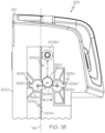
- the guide pin stabilizers 505A, 505A' which would otherwise define a circular footprint, may comprise the truncated portion 509A, as shown in FIG. 18 .
- the guide pin stabilizers 505A, 505A', or at least a portion of the guide pin stabilizers 505A, 505A', are configured to yield in a lateral yielding direction Y perpendicular to the battery insertion and removal axis 140, and to maintain a degree of lateral resilience, when a guiding pin 132A", 132B" enters the restricted-width guide pin gap G.
- FIG. 18 illustrates the lateral yielding direction Y for each guide pin stabilizer 505A, 505A', on one side of the battery body 210, e.g., on the lateral battery face 202A.
- yield may be used herein to refer to a partial compression of the guide pin stabilizers 505A, 505A' such that a truncated portion 509A of the guide pin stabilizers 505A, 505A' compresses by partially deforming in the lateral yielding direction Y as the guiding pin 132A", 132B" enters the restricted-width guide pin gap G.
- each guide pin stabilizer 505A, 505A' should define a degree of structural flexibility and rigidity, most advantageously at the truncated portion 509A of the guide pin stabilizers 505A, 505A'.
- each guide pin stabilizer 505A, 505A' may be formed as a unitary polyurethane structure. More particularly, the guide pin stabilizers 505A, 505A' may be formed from any suitable deformable, resilient material having a Shore A hardness between 50 Shore A and 90 Shore A.
- the longitudinal guide structure 204A of the lateral battery face 202A comprises raised tracks 503A that receive the guide pin stabilizers 505A, 505A'.
- the lateral battery face 202B similarly comprises raised tracks that receive the other pair of guide pin stabilizers.
- the raised tracks 503A define a slot 503A' for receiving an alignment feature 508A' extending from the guide pin stabilizers 505A, 505A'.
- each guide pin stabilizer 505A, 505A' is received within a corresponding slot 503A' to facilitate installation of the guide pin stabilizers 505A, 505A' in the proper orientation, and to help prevent the guide pin stabilizers 505A, 505A' from rotating relative to the lateral battery face 202A.
- Each opposing guide block 160A, 160B comprises a securement portion 162A, 162B and a replaceable portion 164A, 164B.
- the securement portion 162A, 162B of each guide block 160A, 160B is secured to the materials handling vehicle 100.
- the replaceable portion 164A, 164B of each guide block 160A, 160B is seated within the securement portion 162A, 162B, and is removable from the securement portion 162A, 162B without destruction of the securement portion 162A, 162B.
- the replaceable portion 164A, 164B may be fabricated from, a machined polyurethane block and may be fastened to the securement portion 162A, 162B, or press fit into a space formed by the securement portion 162A, 162B.
- the securement portion 162A, 162B may be fabricated from stamped steel or other metal, and can be secured to the materials handling vehicle 100 in a variety of ways, e.g., by welding it to an interior housing 135 of the battery receiving space 130, or by using fasteners to secure it to the interior housing, or another component of the materials handling vehicle.
- the replaceable portion 164A, 164B of each guide block 160A, 160B comprises a lower surface hardness and higher surface friction, relative to the securement portion 162A, 162B.
- the replaceable portion 164A, 164B of each guide block 160A, 160B comprises a friction-inducing surface 166A, 166B and a guiding surface 168A, 168B.
- Each friction-inducing surface 166A, 166B extends along the battery insertion and removal axis 140, parallel to and facing an opposing one of the lateral battery faces 202A, 202B, with the removable battery assembly 200 seated in the battery receiving space 130. More particularly, the friction-inducing surface 166A, 166B of each replaceable portion 164A, 164B of each guide block 160A, 160B extends discontinuously in a direction Z along the battery insertion and removal axis 140 and faces the opposing lateral battery face 202A, 202B in a perpendicular direction X, with the removable battery assembly 200 seated in the battery receiving space 130.
- the longitudinal guide structure 204A of the lateral battery face 202A may be configured as a stepped guide channel comprising a one-sided channel portion 2041A that transitions to a two-sided channel portion 2042A at a channel shoulder 2043A.
- the chamfered leading portion 165A faces the channel shoulder 2043A in the longitudinal guide structure 204A.
- a stepped guide channel may be formed on both lateral battery faces 202A, 202B.
- a backing plate 261A, 261B fabricated from a relatively high strength and rigid metal
- a separate lever plate 263A, 263B fabricated from a material that is flexible enough to facilitate the formation of a functional retention lever, as described herein, it is contemplated that the suitable plastics and other relatively flexible materials with sufficient strength may be used to fabricate a monolithic retention block.
- Each retention block 260A, 260B comprises a retention lever 262A, 262B comprising a fixed end 264A, 264B and a distal end 266A, 266B.
- the distal end 266A, 266B of each retention lever 262A, 262B comprises a terminal lobe 267A, 267B.
- retention lever recess illustrated in FIG. 22 is defined by upper and lower arcuate surfaces, it is contemplated that the retention levers 262A, 262B, and the associated retention lever recesses 265A, 265B, according to the present disclosure may be formed in a variety of ways including, for example, by utilizing planar surfaces to form the retention levers 262A, 262B and the retention lever recesses 265A, 265B.
- the electrical socket 300, the electrical connector 400, the battery body 210, and the battery receiving space 130 are configured to define a standoff gap 414 extending along the battery insertion and removal axis 140 between opposing surfaces 416, 418 of the electrical socket 300 and the electrical connector 400, with the leading face 201 of the removable battery assembly 200 resting on the bottom surface 134 of the battery receiving space 130.
- a reliable electrical connection can be maintained between the electrical socket 300 and the electrical connector 400, even after repeated insertion and removal of the battery assembly 200, by maintaining this standoff gap 414, and by ensuring that the leading face 201 of the removable battery assembly 200 rests on the bottom surface 134 of the battery receiving space 130, under the weight of the battery assembly 200.
- the opposing surfaces 416, 418 of the electrical socket 300 and the electrical connector 400 are horizontally oriented opposing surfaces that are perpendicular to the battery insertion and removal axis 140 and are spaced apart by the standoff gap 414.
- the standoff gap 414 or a gap larger than the standoff gap 414, is maintained between substantially all horizontally oriented opposing surfaces of the electrical socket 300 and the electrical connector 400.
- the battery-side electrical socket 300 may comprise a rim portion 315 that is enclosed by the socket housing 310 and extends generally parallel to the leading face 201 of the battery assembly.
- the vehicle-side electrical connector 400 may comprise a shoulder portion 415 that is enclosed by the connector housing 410 and extends generally parallel to the bottom surface 134 of the battery receiving space 130.
- the rim portion 315 of the battery-side electrical socket extends parallel to the shoulder portion 415 of the vehicle-side electrical connector 400, with the removable battery assembly 200 seated in the battery receiving space 130, and is spaced from the shoulder portion 415 by the standoff gap 414.
- the electrical socket 300 may comprise a set of electrically conductive pin receptacles 320 and the electrical connector 400 may comprise a set of complementary electrically conductive connector pins 420, or vice-verse.
- An outermost portion of the standoff gap 414 can be configured to surround the set of electrically conductive pin receptacles 320 and the set of complementary electrically conductive connector pins 420, with the leading face 201 of the removable battery assembly 200 resting on the bottom surface 134 of the battery receiving space 130, and with the a set of electrically conductive pin receptacles 320 engaging the set of complementary electrically conductive connector pins 420.
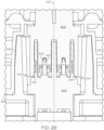
- FIG. 30 depicts a plurality of display screens that may be displayed on an on board battery display 280 of the removable battery assembly 200.
- Battery errors such as, for example, communication errors, input/output errors, and/or battery errors, may be detected, as discussed in more detail herein, and an associated error message may be displayed on the battery display 280 to alert an operator.
- a status of the charge of the intelligent battery may be shown on the battery display 280 when coupled to or removed from the materials handling vehicle 100.
- the battery display 280 may be configured to show one or more operation status display screens 282, one or more charging status display screens 284, one or more standalone battery screens 286, and/or one or more error display screens associated with each status.
- the battery controller 290 may include a printed/protection circuit board (PCB) including a battery management system (BMS) as an intelligent battery feature.
- the BMS may provide battery information to the battery as well as to the vehicle when the battery is electrically coupled to the vehicle to safely manage the battery and prolong battery life.
- the vehicle controller 170 may provide vehicle information (speed, vehicle running hours such as over the life of the vehicle, vehicle errors, etc.) to the battery display 280, which is communicatively coupled to the PCB when the battery 200 is coupled to the vehicle 100 via the battery coupling 350.
- Such errors may include errors indicated by a vehicle safety standard, as indicated via the vehicle controller 170, such as communication errors, input/output errors, and/or battery errors.
- references herein of a component of the present disclosure being "configured” in a particular way, to embody a particular property, or to function in a particular manner, are structural recitations, as opposed to recitations of intended use. More specifically, the references herein to the manner in which a component is “configured” denotes an existing physical condition of the component and, as such, is to be taken as a definite recitation of the structural characteristics of the component.
Landscapes
- Engineering & Computer Science (AREA)
- Transportation (AREA)
- Structural Engineering (AREA)
- Mechanical Engineering (AREA)
- Chemical & Material Sciences (AREA)
- Life Sciences & Earth Sciences (AREA)
- Chemical Kinetics & Catalysis (AREA)
- Electrochemistry (AREA)
- General Chemical & Material Sciences (AREA)
- Civil Engineering (AREA)
- Geology (AREA)
- Power Engineering (AREA)
- Aviation & Aerospace Engineering (AREA)
- Sustainable Energy (AREA)
- Sustainable Development (AREA)
- Combustion & Propulsion (AREA)
- Battery Mounting, Suspending (AREA)
- Handcart (AREA)
- Arrangement Or Mounting Of Propulsion Units For Vehicles (AREA)
- Vehicle Cleaning, Maintenance, Repair, Refitting, And Outriggers (AREA)
Applications Claiming Priority (4)
| Application Number | Priority Date | Filing Date | Title |
|---|---|---|---|
| PCT/CN2021/125869 WO2023065346A1 (en) | 2021-10-22 | 2021-10-22 | Battery guide pins for a battery receiving space of a materials handling vehicle, and materials handling vehicles incorporating the same |
| PCT/CN2022/083994 WO2023184215A1 (en) | 2022-03-30 | 2022-03-30 | Battery guide pins for a battery receiving space of a materials handling vehicle, and materials handling vehicles incorporating the same |
| US17/814,585 US20230129896A1 (en) | 2021-10-22 | 2022-07-25 | Battery guide pins for a battery receiving space of a materials handling vehicle, and materials handling vehicles incorporating the same |
| EP22203046.2A EP4223688A3 (de) | 2021-10-22 | 2022-10-21 | Materialtransportfahrzeug mit abnehmbarer batterieeinheit bestehend aus batterieführungsstiften |
Related Parent Applications (1)
| Application Number | Title | Priority Date | Filing Date |
|---|---|---|---|
| EP22203046.2A Division EP4223688A3 (de) | 2021-10-22 | 2022-10-21 | Materialtransportfahrzeug mit abnehmbarer batterieeinheit bestehend aus batterieführungsstiften |
Publications (2)
| Publication Number | Publication Date |
|---|---|
| EP4397526A2 true EP4397526A2 (de) | 2024-07-10 |
| EP4397526A3 EP4397526A3 (de) | 2024-09-18 |
Family
ID=83995032
Family Applications (2)
| Application Number | Title | Priority Date | Filing Date |
|---|---|---|---|
| EP24176256.6A Pending EP4397526A3 (de) | 2021-10-22 | 2022-10-21 | Batterieführungsstifte für einen batterieaufnahmeraum eines materialhandhabungsfahrzeugs und materialhandhabungsfahrzeuge damit |
| EP22203046.2A Pending EP4223688A3 (de) | 2021-10-22 | 2022-10-21 | Materialtransportfahrzeug mit abnehmbarer batterieeinheit bestehend aus batterieführungsstiften |
Family Applications After (1)
| Application Number | Title | Priority Date | Filing Date |
|---|---|---|---|
| EP22203046.2A Pending EP4223688A3 (de) | 2021-10-22 | 2022-10-21 | Materialtransportfahrzeug mit abnehmbarer batterieeinheit bestehend aus batterieführungsstiften |
Country Status (6)
| Country | Link |
|---|---|
| EP (2) | EP4397526A3 (de) |
| KR (1) | KR20230057982A (de) |
| CN (1) | CN116001546A (de) |
| AU (1) | AU2022252693A1 (de) |
| CA (1) | CA3179143A1 (de) |
| MX (1) | MX2022013262A (de) |
Citations (1)
| Publication number | Priority date | Publication date | Assignee | Title |
|---|---|---|---|---|
| US6343907B1 (en) | 1999-07-26 | 2002-02-05 | Jungheinrich Aktiengesellschaft | Low-lift fork truck |
Family Cites Families (7)
| Publication number | Priority date | Publication date | Assignee | Title |
|---|---|---|---|---|
| JP3526736B2 (ja) * | 1998-01-29 | 2004-05-17 | 日産ディーゼル工業株式会社 | バッテリ固定装置 |
| US7320843B2 (en) * | 2004-02-27 | 2008-01-22 | Great Stuff, Inc. | Battery assembly with shielded terminals |
| US8653786B2 (en) * | 2008-04-25 | 2014-02-18 | Black & Decker Inc. | Cordless mower including battery with two charging connectors |
| EP3309001B1 (de) * | 2016-10-14 | 2021-09-29 | EP Equipment Co., Ltd. | Steckbare batterievorrichtung für materialhandhabungsausrüstung |
| US10062885B2 (en) * | 2016-11-07 | 2018-08-28 | Thomas Gerald Tessier | Battery tray glide system |
| US11233291B2 (en) * | 2019-04-03 | 2022-01-25 | The Raymond Corporation | Systems and methods for a modular battery system |
| CN113471613A (zh) * | 2020-03-12 | 2021-10-01 | 比亚迪股份有限公司 | 车用电池箱及车辆 |
-
2022
- 2022-10-10 AU AU2022252693A patent/AU2022252693A1/en active Pending
- 2022-10-17 CA CA3179143A patent/CA3179143A1/en active Pending
- 2022-10-20 MX MX2022013262A patent/MX2022013262A/es unknown
- 2022-10-21 CN CN202211296835.7A patent/CN116001546A/zh active Pending
- 2022-10-21 EP EP24176256.6A patent/EP4397526A3/de active Pending
- 2022-10-21 EP EP22203046.2A patent/EP4223688A3/de active Pending
- 2022-10-21 KR KR1020220136276A patent/KR20230057982A/ko unknown
Patent Citations (1)
| Publication number | Priority date | Publication date | Assignee | Title |
|---|---|---|---|---|
| US6343907B1 (en) | 1999-07-26 | 2002-02-05 | Jungheinrich Aktiengesellschaft | Low-lift fork truck |
Also Published As
| Publication number | Publication date |
|---|---|
| CN116001546A (zh) | 2023-04-25 |
| MX2022013262A (es) | 2023-04-24 |
| AU2022252693A1 (en) | 2023-05-11 |
| EP4397526A3 (de) | 2024-09-18 |
| EP4223688A2 (de) | 2023-08-09 |
| KR20230057982A (ko) | 2023-05-02 |
| EP4223688A3 (de) | 2023-11-08 |
| CA3179143A1 (en) | 2023-04-22 |
Similar Documents
| Publication | Publication Date | Title |
|---|---|---|
| WO2023065330A1 (en) | Battery locking mechanisms, removable battery assemblies, and materials handling vehicles incorporating the same | |
| WO2023065350A1 (en) | Battery display, battery coupling, and materials handling vehicles incorporating the same | |
| US20230129896A1 (en) | Battery guide pins for a battery receiving space of a materials handling vehicle, and materials handling vehicles incorporating the same | |
| WO2023065344A1 (en) | Battery retention blocks for a battery receiving space of a materials handling vehicle, and materials handling vehicles incorporating the same | |
| CN110998898A (zh) | 用于叉车的模块化锂离子电池系统 | |
| EP2787557B1 (de) | Batteriepacks für Elektrowerkzeuge | |
| WO2023065346A1 (en) | Battery guide pins for a battery receiving space of a materials handling vehicle, and materials handling vehicles incorporating the same | |
| WO2023065347A1 (en) | Battery guide blocks for a battery receiving space of a materials handling vehicle, and materials handling vehicles incorporating the same | |
| EP4223688A2 (de) | Materialtransportfahrzeug mit abnehmbarer batterieeinheit bestehend aus batterieführungsstiften | |
| WO2023184215A1 (en) | Battery guide pins for a battery receiving space of a materials handling vehicle, and materials handling vehicles incorporating the same | |
| EP4212471A1 (de) | Batterieführungsblöcke für einen batterieaufnahmeraum eines materialhandhabungsfahrzeugs und materialhandhabungsfahrzeuge damit | |
| EP4169868A1 (de) | Flurförderzeug mit batterieverriegelungsmechanismus und entfernbare batterieanordnung | |
| EP4169869A1 (de) | Batteriekupplung und diese enthaltende materialhandhabungsfahrzeuge | |
| EP4212470A1 (de) | Batteriehalteblöcke für einen batterieaufnahmeraum eines materialhandhabungsfahrzeugs und materialhandhabungsfahrzeuge damit | |
| US20230356606A1 (en) | Supply device and modular supply system so obtained | |
| CN216940622U (zh) | 一种智能工具车 | |
| US12107449B2 (en) | Electrical-device system and detachable DC power source | |
| CN116190900B (zh) | 固定支架、电池以及用电设备 | |
| JP2023549274A (ja) | 電池ケース、電池、ブラケット及び電力消費装置 |
Legal Events
| Date | Code | Title | Description |
|---|---|---|---|
| PUAI | Public reference made under article 153(3) epc to a published international application that has entered the european phase |
Free format text: ORIGINAL CODE: 0009012 |
|
| STAA | Information on the status of an ep patent application or granted ep patent |
Free format text: STATUS: THE APPLICATION HAS BEEN PUBLISHED |
|
| AC | Divisional application: reference to earlier application |
Ref document number: 4223688 Country of ref document: EP Kind code of ref document: P |
|
| AK | Designated contracting states |
Kind code of ref document: A2 Designated state(s): AL AT BE BG CH CY CZ DE DK EE ES FI FR GB GR HR HU IE IS IT LI LT LU LV MC ME MK MT NL NO PL PT RO RS SE SI SK SM TR |
|
| PUAL | Search report despatched |
Free format text: ORIGINAL CODE: 0009013 |
|
| REG | Reference to a national code |
Ref country code: DE Ref legal event code: R079 Free format text: PREVIOUS MAIN CLASS: B60L0050600000 Ipc: B66F0009075000 |
|
| AK | Designated contracting states |
Kind code of ref document: A3 Designated state(s): AL AT BE BG CH CY CZ DE DK EE ES FI FR GB GR HR HU IE IS IT LI LT LU LV MC ME MK MT NL NO PL PT RO RS SE SI SK SM TR |
|
| RIC1 | Information provided on ipc code assigned before grant |
Ipc: H01M 50/262 20210101ALI20240815BHEP Ipc: H01M 50/249 20210101ALI20240815BHEP Ipc: H01M 50/209 20210101ALI20240815BHEP Ipc: B66F 9/065 20060101ALI20240815BHEP Ipc: B62B 5/00 20060101ALI20240815BHEP Ipc: B62B 3/06 20060101ALI20240815BHEP Ipc: B60L 53/80 20190101ALI20240815BHEP Ipc: B60L 50/64 20190101ALI20240815BHEP Ipc: B60L 50/60 20190101ALI20240815BHEP Ipc: B66F 9/075 20060101AFI20240815BHEP |