EP4397495A1 - Flüssigkeitsausstossvorrichtung, steuerungsverfahren und programmhintergrund - Google Patents
Flüssigkeitsausstossvorrichtung, steuerungsverfahren und programmhintergrund Download PDFInfo
- Publication number
- EP4397495A1 EP4397495A1 EP23214652.2A EP23214652A EP4397495A1 EP 4397495 A1 EP4397495 A1 EP 4397495A1 EP 23214652 A EP23214652 A EP 23214652A EP 4397495 A1 EP4397495 A1 EP 4397495A1
- Authority
- EP
- European Patent Office
- Prior art keywords
- printing
- liquid
- circulating pump
- driving
- ejecting apparatus
- Prior art date
- Legal status (The legal status is an assumption and is not a legal conclusion. Google has not performed a legal analysis and makes no representation as to the accuracy of the status listed.)
- Pending
Links
Images






Classifications
-
- B—PERFORMING OPERATIONS; TRANSPORTING
- B41—PRINTING; LINING MACHINES; TYPEWRITERS; STAMPS
- B41J—TYPEWRITERS; SELECTIVE PRINTING MECHANISMS, i.e. MECHANISMS PRINTING OTHERWISE THAN FROM A FORME; CORRECTION OF TYPOGRAPHICAL ERRORS
- B41J2/00—Typewriters or selective printing mechanisms characterised by the printing or marking process for which they are designed
- B41J2/005—Typewriters or selective printing mechanisms characterised by the printing or marking process for which they are designed characterised by bringing liquid or particles selectively into contact with a printing material
- B41J2/01—Ink jet
- B41J2/17—Ink jet characterised by ink handling
- B41J2/175—Ink supply systems ; Circuit parts therefor
-
- B—PERFORMING OPERATIONS; TRANSPORTING
- B41—PRINTING; LINING MACHINES; TYPEWRITERS; STAMPS
- B41J—TYPEWRITERS; SELECTIVE PRINTING MECHANISMS, i.e. MECHANISMS PRINTING OTHERWISE THAN FROM A FORME; CORRECTION OF TYPOGRAPHICAL ERRORS
- B41J2/00—Typewriters or selective printing mechanisms characterised by the printing or marking process for which they are designed
- B41J2/005—Typewriters or selective printing mechanisms characterised by the printing or marking process for which they are designed characterised by bringing liquid or particles selectively into contact with a printing material
- B41J2/01—Ink jet
- B41J2/135—Nozzles
- B41J2/14—Structure thereof only for on-demand ink jet heads
- B41J2/14016—Structure of bubble jet print heads
- B41J2/14024—Assembling head parts
-
- B—PERFORMING OPERATIONS; TRANSPORTING
- B41—PRINTING; LINING MACHINES; TYPEWRITERS; STAMPS
- B41J—TYPEWRITERS; SELECTIVE PRINTING MECHANISMS, i.e. MECHANISMS PRINTING OTHERWISE THAN FROM A FORME; CORRECTION OF TYPOGRAPHICAL ERRORS
- B41J2/00—Typewriters or selective printing mechanisms characterised by the printing or marking process for which they are designed
- B41J2/005—Typewriters or selective printing mechanisms characterised by the printing or marking process for which they are designed characterised by bringing liquid or particles selectively into contact with a printing material
- B41J2/01—Ink jet
- B41J2/135—Nozzles
- B41J2/165—Prevention or detection of nozzle clogging, e.g. cleaning, capping or moistening for nozzles
-
- B—PERFORMING OPERATIONS; TRANSPORTING
- B41—PRINTING; LINING MACHINES; TYPEWRITERS; STAMPS
- B41J—TYPEWRITERS; SELECTIVE PRINTING MECHANISMS, i.e. MECHANISMS PRINTING OTHERWISE THAN FROM A FORME; CORRECTION OF TYPOGRAPHICAL ERRORS
- B41J2/00—Typewriters or selective printing mechanisms characterised by the printing or marking process for which they are designed
- B41J2/005—Typewriters or selective printing mechanisms characterised by the printing or marking process for which they are designed characterised by bringing liquid or particles selectively into contact with a printing material
- B41J2/01—Ink jet
- B41J2/135—Nozzles
- B41J2/165—Prevention or detection of nozzle clogging, e.g. cleaning, capping or moistening for nozzles
- B41J2/16517—Cleaning of print head nozzles
- B41J2/1652—Cleaning of print head nozzles by driving a fluid through the nozzles to the outside thereof, e.g. by applying pressure to the inside or vacuum at the outside of the print head
- B41J2/16532—Cleaning of print head nozzles by driving a fluid through the nozzles to the outside thereof, e.g. by applying pressure to the inside or vacuum at the outside of the print head by applying vacuum only
-
- B—PERFORMING OPERATIONS; TRANSPORTING
- B41—PRINTING; LINING MACHINES; TYPEWRITERS; STAMPS
- B41J—TYPEWRITERS; SELECTIVE PRINTING MECHANISMS, i.e. MECHANISMS PRINTING OTHERWISE THAN FROM A FORME; CORRECTION OF TYPOGRAPHICAL ERRORS
- B41J2/00—Typewriters or selective printing mechanisms characterised by the printing or marking process for which they are designed
- B41J2/005—Typewriters or selective printing mechanisms characterised by the printing or marking process for which they are designed characterised by bringing liquid or particles selectively into contact with a printing material
- B41J2/01—Ink jet
- B41J2/17—Ink jet characterised by ink handling
- B41J2/175—Ink supply systems ; Circuit parts therefor
- B41J2/17503—Ink cartridges
- B41J2/1752—Mounting within the printer
- B41J2/17523—Ink connection
-
- B—PERFORMING OPERATIONS; TRANSPORTING
- B41—PRINTING; LINING MACHINES; TYPEWRITERS; STAMPS
- B41J—TYPEWRITERS; SELECTIVE PRINTING MECHANISMS, i.e. MECHANISMS PRINTING OTHERWISE THAN FROM A FORME; CORRECTION OF TYPOGRAPHICAL ERRORS
- B41J2/00—Typewriters or selective printing mechanisms characterised by the printing or marking process for which they are designed
- B41J2/005—Typewriters or selective printing mechanisms characterised by the printing or marking process for which they are designed characterised by bringing liquid or particles selectively into contact with a printing material
- B41J2/01—Ink jet
- B41J2/17—Ink jet characterised by ink handling
- B41J2/175—Ink supply systems ; Circuit parts therefor
- B41J2/17596—Ink pumps, ink valves
-
- B—PERFORMING OPERATIONS; TRANSPORTING
- B41—PRINTING; LINING MACHINES; TYPEWRITERS; STAMPS
- B41J—TYPEWRITERS; SELECTIVE PRINTING MECHANISMS, i.e. MECHANISMS PRINTING OTHERWISE THAN FROM A FORME; CORRECTION OF TYPOGRAPHICAL ERRORS
- B41J2/00—Typewriters or selective printing mechanisms characterised by the printing or marking process for which they are designed
- B41J2/005—Typewriters or selective printing mechanisms characterised by the printing or marking process for which they are designed characterised by bringing liquid or particles selectively into contact with a printing material
- B41J2/01—Ink jet
- B41J2/17—Ink jet characterised by ink handling
- B41J2/18—Ink recirculation systems
- B41J2/185—Ink-collectors; Ink-catchers
-
- B—PERFORMING OPERATIONS; TRANSPORTING
- B41—PRINTING; LINING MACHINES; TYPEWRITERS; STAMPS
- B41J—TYPEWRITERS; SELECTIVE PRINTING MECHANISMS, i.e. MECHANISMS PRINTING OTHERWISE THAN FROM A FORME; CORRECTION OF TYPOGRAPHICAL ERRORS
- B41J29/00—Details of, or accessories for, typewriters or selective printing mechanisms not otherwise provided for
- B41J29/38—Drives, motors, controls or automatic cut-off devices for the entire printing mechanism
- B41J29/393—Devices for controlling or analysing the entire machine ; Controlling or analysing mechanical parameters involving printing of test patterns
-
- B—PERFORMING OPERATIONS; TRANSPORTING
- B41—PRINTING; LINING MACHINES; TYPEWRITERS; STAMPS
- B41J—TYPEWRITERS; SELECTIVE PRINTING MECHANISMS, i.e. MECHANISMS PRINTING OTHERWISE THAN FROM A FORME; CORRECTION OF TYPOGRAPHICAL ERRORS
- B41J2/00—Typewriters or selective printing mechanisms characterised by the printing or marking process for which they are designed
- B41J2/005—Typewriters or selective printing mechanisms characterised by the printing or marking process for which they are designed characterised by bringing liquid or particles selectively into contact with a printing material
- B41J2/01—Ink jet
- B41J2/17—Ink jet characterised by ink handling
- B41J2/18—Ink recirculation systems
-
- B—PERFORMING OPERATIONS; TRANSPORTING
- B41—PRINTING; LINING MACHINES; TYPEWRITERS; STAMPS
- B41J—TYPEWRITERS; SELECTIVE PRINTING MECHANISMS, i.e. MECHANISMS PRINTING OTHERWISE THAN FROM A FORME; CORRECTION OF TYPOGRAPHICAL ERRORS
- B41J2/00—Typewriters or selective printing mechanisms characterised by the printing or marking process for which they are designed
- B41J2/005—Typewriters or selective printing mechanisms characterised by the printing or marking process for which they are designed characterised by bringing liquid or particles selectively into contact with a printing material
- B41J2/01—Ink jet
- B41J2/17—Ink jet characterised by ink handling
- B41J2/19—Ink jet characterised by ink handling for removing air bubbles
-
- B—PERFORMING OPERATIONS; TRANSPORTING
- B41—PRINTING; LINING MACHINES; TYPEWRITERS; STAMPS
- B41J—TYPEWRITERS; SELECTIVE PRINTING MECHANISMS, i.e. MECHANISMS PRINTING OTHERWISE THAN FROM A FORME; CORRECTION OF TYPOGRAPHICAL ERRORS
- B41J2202/00—Embodiments of or processes related to ink-jet or thermal heads
- B41J2202/01—Embodiments of or processes related to ink-jet heads
- B41J2202/07—Embodiments of or processes related to ink-jet heads dealing with air bubbles
-
- B—PERFORMING OPERATIONS; TRANSPORTING
- B41—PRINTING; LINING MACHINES; TYPEWRITERS; STAMPS
- B41J—TYPEWRITERS; SELECTIVE PRINTING MECHANISMS, i.e. MECHANISMS PRINTING OTHERWISE THAN FROM A FORME; CORRECTION OF TYPOGRAPHICAL ERRORS
- B41J2202/00—Embodiments of or processes related to ink-jet or thermal heads
- B41J2202/01—Embodiments of or processes related to ink-jet heads
- B41J2202/12—Embodiments of or processes related to ink-jet heads with ink circulating through the whole print head
-
- B—PERFORMING OPERATIONS; TRANSPORTING
- B41—PRINTING; LINING MACHINES; TYPEWRITERS; STAMPS
- B41J—TYPEWRITERS; SELECTIVE PRINTING MECHANISMS, i.e. MECHANISMS PRINTING OTHERWISE THAN FROM A FORME; CORRECTION OF TYPOGRAPHICAL ERRORS
- B41J2202/00—Embodiments of or processes related to ink-jet or thermal heads
- B41J2202/01—Embodiments of or processes related to ink-jet heads
- B41J2202/20—Modules
Definitions
- the present disclosure relates to a liquid ejecting apparatus, a control method, and a storage medium.
- Inkjet printing heads which perform printing on a printing medium by ejecting liquids such as inks have been known as printing heads to be used in printing apparatuses.
- Printing apparatuses equipped with an inkjet printing head are configured to be supplied with liquids from ink tanks into the printing head through supply channels and print an image based on image data designated by a user.
- the growing demand for smaller apparatus sizes has made printing heads smaller and smaller in size. As a result, the circulation channels have become so fine that their flow resistance is high. This makes the channels prone to clogging.
- Japanese Patent Laid-Open No. 2012-148471 proposes a method to prevent clogging of a circulation channel by controlling the output of a pump such that the flow velocity of a liquid inside the circulation channel will be more than or equal to a predetermined value.
- the present invention in its first aspect provides a liquid ejecting apparatus as specified in claims 1 to 17.
- the present invention in its second aspect provides a control method as specified in claims 18
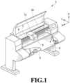
- the printing medium P is conveyed in the conveyance direction by a sheet feeding roller driven by a sheet feeding motor 5 (see Fig. 3 ) via gears and a spool 6 holding the printing medium P.
- the printing head 9, which is detachably attachable, is mounted on a carriage unit 11.
- a carriage motor 119 (see Fig. 3 ) scans the carriage unit 11 along a guide shaft 8 extending in the main scanning direction at a predetermined conveyance position.
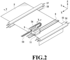
- Fig. 2 is a schematic perspective view of an example of a configuration of the printing apparatus 1 using the printing head 9.
- the printing head 9 being an inkjet printing head in the present embodiment is fixed to and supported on the carriage unit 11, which is provided to the printing apparatus 1, by a positioning device and electrical contacts of the carriage unit 11.
- the carriage unit 11 moves in the main scanning direction, which is the direction of an arrow X, along the guide shaft 8.
- the printing medium P is conveyed in the conveyance direction, which is the direction of an arrow Y, by conveying rollers 55, 56, 57, and 58.
- Ink circulating units 54 are mounted on the printing head 9 and, as will be described later, the inks are circulated in a printing element unit.
- the printing apparatus 1 is provided with ink supply tubes 59 connected to ink tanks not illustrated which serve as supply sources of inks (liquids), and the inks inside the ink tanks are supplied to the printing head 9.
- Fig. 3 is a diagram illustrating an example of a configuration of a control circuit in the printing apparatus 1 in the present embodiment.
- a programmable peripheral interface (hereinafter referred to as "PPI") 101 receives a printing information signal containing an instruction signal (command) and printing data which is sent from a host computer 300, and transfers it to a micro processing unit (MPU) 102.
- the PPI 101 outputs status information of the printing apparatus 1 to the host computer 300 as necessary.
- the MPU 102 is a control unit that controls components in the printing apparatus 1 in accordance with a control program stored in a control read-only memory (ROM) 105.
- a random-access memory (RAM) 103 stores the receive signals.
- the RAM 103 is also used as a work area for the MPU 102 and temporarily stores various data.
- Motor drivers 114, 115, and 116 drive a capping motor 113, the carriage motor 119, and the sheet feeding motor 5 under control of the MPU 102, respectively.
- the printing apparatus 1 in the present embodiment is included in a printing system including the host computer 300, which supplies the printing information signal to the printing apparatus 1.
- the host computer 300 adds necessary commands to a head section of printing data in a case of sending the printing data to the printing apparatus 1 through a parallel port, an infrared port, a network, or the like.
- the added commands include the type of the printing medium to print the image, the size of the printing medium, the printing quality, whether or not to perform automatic object determination, and the like.
- Examples of the type of the printing medium include types such as plain paper, an overhead projector (OHP) sheet, and glossy paper as well as special types of printing media such as a transfer film, cardboard, banner paper, and the like.
- Examples of the size of the printing medium include A0, A1, A2, B0, B1, B2, and the like.
- Examples of the printing quality include draft, high definition, middle definition, exaggeration of a particular color, monochrome or color, and the like.
- information identifying whether or not to apply that liquid or the like may be included as a command in the printing data.
- the printing apparatus 1 reads data necessary for printing from the control ROM 105 and performs printing on the printing medium P based on the data.
- the data necessary for printing include data for determining the number of printing passes in a case of performing the multipass printing mentioned above, the amount of each ink to be applied to the printing medium per unit area, the printing direction, and the like.
- the driving conditions include the form of driving pulses to be applied to heating parts, the application time, and the like.
- the supply channel 130 in Fig. 6 is connected to the individual supply channels 18 through the joint member 38 illustrated in Fig. 5 .
- the individual collection channels 19 are connected to the collection channel 140 through the joint member 38.
- the valve 504b is configured to open in response to pressurization of the inside of the pump chamber 503 and close the ink discharge port 502 in response to depressurization of the inside of the pump chamber 503.
- the material of the valves 504a and 504b is one which is deformable by the internal pressure of the pump chamber 503. Examples of such a material include elastic materials such as ethylene propylene diene monomer (EPDM) and elastomers, and films and thin plates of polypropylene and the like. However, the material is not limited to these.
- the pump chamber 503 is formed by joining a housing 505 and a diaphragm 506. Deformation of the diaphragm 506 changes the pressure inside the pump chamber 503.
- the pressure inside the pump chamber 503 rises.
- the valve 504b on the ink discharge port 502 side opens, so that the ink contained in the pump chamber 503 is discharged.
- the valve 504a on the ink supply port 501 side abuts the ink supply port 501, thereby preventing backflow of the ink into the ink supply port 501 from the pump chamber 503.
- the pressure inside the pump chamber 503 drops.
- the valve 504a on the ink supply port 501 side opens, so that the ink is supplied into the pump chamber 503.
- the valve 504b on the ink discharge port 502 side abuts the ink discharge port 502, thereby preventing backflow of the ink into the pump chamber 503 from the ink discharge port 502.
- the MPU 102 performs a process of sucking the inks out of the ejection orifices by using the suction mechanism as described with reference to Fig. 14 .
- choking suction is performed, for example.
- the specified time T1 for which to perform bubble discharge circulation after cleaning that allows a high intensity of recovery may be controlled to be longer than that of bubble discharge circulation performed after cleaning that allows a low intensity of recovery.
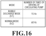
- the specified time T1 for which to drive each circulating pump 500 in the bubble discharge mode may be set to be shorter than 60 seconds. This makes it possible to implement bubble discharge control suitable for the amount of bubbles to be generated corresponding to the intensity of recovery by cleaning.
- each circulating pump 500 may be a pump configured to operate with a mechanism that physically squeezes a tube with rollers, like a tube pump. It goes without saying that, regardless of the configuration of the circulating pump 500, the method of the present embodiment, which reduces the effect of bubbles inside the circulation channel, is applicable by changing parameters for controlling the number of times of driving of the pump.
- the MPU 102 determines the ink circulation time in the bubble discharge mode (bubble discharge circulation time).
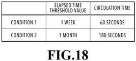
- the MPU 102 determines the bubble discharge circulation time such that the longer the time elapsed since the last-performed printing operation, the longer the bubble discharge circulation time.
- the MPU 102 sets 60 seconds under the condition 1 as the bubble discharge circulation time in a case where the time elapsed since the last-performed printing operation is more than or equal to 1 week and less than 1 month.
- the MPU 102 sets 180 seconds under the condition 2 as the bubble discharge circulation time. For example, in a case where the printing apparatus 1 has been left unused for half a year or longer, 180 seconds, which is the circulation time under the condition 2, is set.
- the above is an example of a method of controlling bubble discharge circulation in a case where no printing operation has been performed for a predetermined time.
- the printing apparatus 1 In a case where the printing apparatus 1 has been left unused for a long time and no printing operation has been performed for a predetermined time, it is possible that many bubbles have been generated inside the circulation channels due to insufficient gas barrier properties of the resin of the printing head 9 and the tubes forming the circulation channels. For this reason, in the present embodiment, the printing apparatus 1 is controlled to perform bubble discharge circulation before performing a printing operation in a case where the printing apparatus 1 is caused to operate again after being left unused for a long time. Such control prevents poor ink circulation due to bubbles and provides a condition suitable printing operations.
- cleaning involving a suction operation may be performed before a printing operation.
- control may be performed to perform cleaning involving a suction operation according to the time elapsed since the last-performed printing operation, and perform bubble discharge circulation after the suction operation.
- a step of determining whether to perform cleaning involving a suction operation may be added to the flowchart of Fig. 17 .
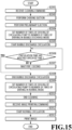
- the process flow of Fig. 15 or Fig. 17 may be implemented according to the time elapsed since the last-performed printing operation.
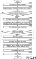
- the MPU 102 determines whether the amount of bubbles generated in the circulation channels is larger than a predetermined value or smaller than the predetermined value.
- the amount of bubbles generated is determined by analogy. There are several possible methods of analogizing the amount of bubbles generated.
- MANY represents a case where the amount of bubbles generated inside the circulation channels is analogized to be more than or equal to the predetermined value
- FEW represents a case where the amount of bubbles generated inside the circulation channels is analogized to be less than the predetermined value.
- a calculation formula to analogize the amount of bubbles generated may be derived by empirically measuring amounts of bubbles generated corresponding to times elapsed since the last-performed printing operation and environmental temperatures of the printing apparatus 1 in a state of being left unused. Then, the amount of bubbles generated may be calculated by plugging the elapsed time and the environmental temperature into the calculation formula to analogize the amount of bubbles generated.
- a method in which the amount of bubbles generated is analogized based on the error status during the last-performed printing operation may be used.
- the temperature of the printing head 9 is monitored in order to protect the printing head 9 and the main body of the printing apparatus 1, and the printing apparatus 1 is equipped with a protection function to forcibly stop an image printing operation in a case where the temperature becomes a predetermined value or higher.
- the temperature of the printing head 9 has risen above an expected temperature, it is possible that pressure chambers near nozzles (ejection orifices) are filled with bubbles instead of the inks due to some trouble and have been heated in an empty state.
- the MPU 102 may check a history indicating whether the temperature of the printing head 9 has become high in S1902, and determine that the amount of bubbles generated inside the circulation channels is more than the predetermined value in a case where a high-temperature error had occurred.
- the printing apparatus 1 may experience errors such as a paper jam.
- a paper jam sometimes occurs due to contact between a sheet being a printing medium and the liquid surfaces in the nozzle (ejection orifice) opening portions of the printing head 9.
- menisci are formed on the liquid surfaces in the nozzle (ejection orifice) opening portions of the printing head 9 by surface tension, so that the inks do not drip out of the nozzles (ejection orifices).
- physical contact with a conveyed sheet may break the menisci. If the menisci are broken, the inks are discharged out of the nozzles (ejection orifices) even without performing control to discharge the inks. Thus, bubbles are likely to get in in place of the inks. For this reason, after a particular error like a paper jam occurs, the MPU 102 may determine in S1902 that the amount of bubbles generated inside the circulation channels is more than the predetermined value.
- the MPU 102 determines whether or not the amount of bubbles generated inside the channels was determined to be more than or equal to the predetermined value in S1902. The MPU 102 advances the processing to S1904 if determining that the amount of bubbles generated was more than or equal to the predetermined value. The MPU 102 advances the processing to S1910 if determining that the amount of bubbles generated was less than the predetermined value.
- S1904 to S1912 are similar to S1704 to S1712 in FIG. 17 , and detailed description thereof is therefore omitted below.
- Various kinds of control such as increasing the bubble discharge circulation time in S1904 according to the analogized amount of bubbles generated may be performed.
- the time for which to drive the circulating pump 500 at the number of times of driving fr1 in the bubble discharge mode may be controlled to be longer , the larger the analogized amount of bubbles generated in the circulation channel.
- each ink circulation channel is equipped with a sensor that measures an amount of dissolution in the liquid, and the amount of bubbles generated is analogized to be more than a predetermined value in a case where the value of the sensor output is more than or equal to a certain value.
- Any analogization methods are applicable to the present embodiment.
- Embodiment(s) of the present disclosure can also be realized by a computer of a system or apparatus that reads out and executes computer executable instructions (e.g., one or more programs) recorded on a storage medium (which may also be referred to more fully as a 'non-transitory computer-readable storage medium') to perform the functions of one or more of the above-described embodiment(s) and/or that includes one or more circuits (e.g., application specific integrated circuit (ASIC)) for performing the functions of one or more of the above-described embodiment(s), and by a method performed by the computer of the system or apparatus by, for example, reading out and executing the computer executable instructions from the storage medium to perform the functions of one or more of the above-described embodiment(s) and/or controlling the one or more circuits to perform the functions of one or more of the above-described embodiment(s).
- computer executable instructions e.g., one or more programs
- a storage medium which may also be referred to more fully as
- the computer may comprise one or more processors (e.g., central processing unit (CPU), micro processing unit (MPU)) and may include a network of separate computers or separate processors to read out and execute the computer executable instructions.
- the computer executable instructions may be provided to the computer, for example, from a network or the storage medium.
- the storage medium may include, for example, one or more of a hard disk, a random-access memory (RAM), a read only memory (ROM), a storage of distributed computing systems, an optical disk (such as a compact disc (CD), digital versatile disc (DVD), or Blu-ray Disc (BD) TM ), a flash memory device, a memory card, and the like.
- a liquid ejecting apparatus (1) includes: a circulation channel; a circulating pump (500) configured to circulate a liquid in the circulation channel; and a control unit (102) configured to perform control that drives the circulating pump at a first number of times of driving in a case of performing a printing operation in which the liquid is ejected onto a printing medium, and drives the circulating pump at a second number of times of driving smaller than the first number of times of driving in a predetermined case which is before performing the printing operation.
Landscapes
- Ink Jet (AREA)
- Engineering & Computer Science (AREA)
- Quality & Reliability (AREA)
Applications Claiming Priority (1)
| Application Number | Priority Date | Filing Date | Title |
|---|---|---|---|
| JP2022201568A JP2024086442A (ja) | 2022-12-16 | 2022-12-16 | 液体吐出装置、制御方法、およびプログラム |
Publications (1)
| Publication Number | Publication Date |
|---|---|
| EP4397495A1 true EP4397495A1 (de) | 2024-07-10 |
Family
ID=89121582
Family Applications (1)
| Application Number | Title | Priority Date | Filing Date |
|---|---|---|---|
| EP23214652.2A Pending EP4397495A1 (de) | 2022-12-16 | 2023-12-06 | Flüssigkeitsausstossvorrichtung, steuerungsverfahren und programmhintergrund |
Country Status (4)
| Country | Link |
|---|---|
| US (1) | US12545031B2 (de) |
| EP (1) | EP4397495A1 (de) |
| JP (1) | JP2024086442A (de) |
| CN (1) | CN118205311A (de) |
Citations (3)
| Publication number | Priority date | Publication date | Assignee | Title |
|---|---|---|---|---|
| JP2012148471A (ja) | 2011-01-19 | 2012-08-09 | Seiko Epson Corp | 流路ユニット、および、画像形成装置 |
| US20190299592A1 (en) * | 2018-03-30 | 2019-10-03 | Canon Kabushiki Kaisha | Image forming apparatus and control method of image forming apparatus |
| US20200108626A1 (en) * | 2018-10-05 | 2020-04-09 | Canon Kabushiki Kaisha | Inkjet printing apparatus and inkjet printing method |
Family Cites Families (22)
| Publication number | Priority date | Publication date | Assignee | Title |
|---|---|---|---|---|
| JP4994648B2 (ja) | 2005-11-30 | 2012-08-08 | キヤノン株式会社 | インクタンクおよびこれを用いるインクジェット記録装置 |
| US7950790B2 (en) | 2006-09-11 | 2011-05-31 | Canon Kabushiki Kaisha | Ink container and ink jet recording apparatus |
| JP5031506B2 (ja) | 2007-10-12 | 2012-09-19 | キヤノン株式会社 | インクタンクおよび記録装置 |
| JP5106134B2 (ja) | 2008-01-10 | 2012-12-26 | キヤノン株式会社 | 液体収納容器 |
| JP5550220B2 (ja) | 2008-08-29 | 2014-07-16 | キヤノン株式会社 | インクタンク |
| JP5489629B2 (ja) * | 2008-12-05 | 2014-05-14 | キヤノン株式会社 | 記録装置 |
| JP5600910B2 (ja) * | 2009-08-31 | 2014-10-08 | セイコーエプソン株式会社 | 液体噴射装置及び液体噴射装置における液体噴射ヘッドのクリーニング方法 |
| JP5340240B2 (ja) | 2010-04-02 | 2013-11-13 | キヤノン株式会社 | タンクおよびこれを備えたプリンタ |
| US8529037B2 (en) | 2011-02-03 | 2013-09-10 | Canon Kabushiki Kaisha | Ink tank and production process of ink tank |
| JP5615392B2 (ja) | 2012-02-23 | 2014-10-29 | キヤノン株式会社 | 液体収納容器およびそれを装着可能な装置 |
| JP5979906B2 (ja) | 2012-02-23 | 2016-08-31 | キヤノン株式会社 | 液体収納容器およびそれを装着可能な装置 |
| JP5960345B2 (ja) | 2013-09-18 | 2016-08-02 | キヤノン株式会社 | インクカートリッジおよびインクジェットプリンタ |
| CN105722684B (zh) | 2013-09-18 | 2017-12-05 | 佳能株式会社 | 墨盒和喷墨打印机 |
| JP6355442B2 (ja) | 2014-06-10 | 2018-07-11 | キヤノン株式会社 | 液体収容容器の液体充填方法 |
| US9375938B2 (en) | 2014-06-27 | 2016-06-28 | Canon Kabushiki Kaisha | Ink cartridge and ink jet printing apparatus |
| JP6395471B2 (ja) | 2014-06-27 | 2018-09-26 | キヤノン株式会社 | 液体収納容器及び液体吐出装置 |
| JP6385163B2 (ja) | 2014-06-27 | 2018-09-05 | キヤノン株式会社 | 液体収納容器及び液体吐出装置 |
| JP6611564B2 (ja) | 2015-10-30 | 2019-11-27 | キヤノン株式会社 | 液体収納ボトルおよび液体収納ボトルのパッケージ |
| JP7057111B2 (ja) | 2017-12-01 | 2022-04-19 | キヤノン株式会社 | シール機構の製造方法 |
| US11077670B2 (en) | 2018-01-30 | 2021-08-03 | Canon Kabushiki Kaisha | Inkjet printing apparatus and ink filling method |
| JP7242231B2 (ja) | 2018-09-28 | 2023-03-20 | キヤノン株式会社 | パッド電極を有する部材、記録装置 |
| JP7418995B2 (ja) | 2019-08-15 | 2024-01-22 | キヤノン株式会社 | 記録装置 |
-
2022
- 2022-12-16 JP JP2022201568A patent/JP2024086442A/ja active Pending
-
2023
- 2023-11-30 US US18/524,987 patent/US12545031B2/en active Active
- 2023-12-06 EP EP23214652.2A patent/EP4397495A1/de active Pending
- 2023-12-07 CN CN202311674500.9A patent/CN118205311A/zh active Pending
Patent Citations (3)
| Publication number | Priority date | Publication date | Assignee | Title |
|---|---|---|---|---|
| JP2012148471A (ja) | 2011-01-19 | 2012-08-09 | Seiko Epson Corp | 流路ユニット、および、画像形成装置 |
| US20190299592A1 (en) * | 2018-03-30 | 2019-10-03 | Canon Kabushiki Kaisha | Image forming apparatus and control method of image forming apparatus |
| US20200108626A1 (en) * | 2018-10-05 | 2020-04-09 | Canon Kabushiki Kaisha | Inkjet printing apparatus and inkjet printing method |
Also Published As
| Publication number | Publication date |
|---|---|
| US12545031B2 (en) | 2026-02-10 |
| US20240198689A1 (en) | 2024-06-20 |
| JP2024086442A (ja) | 2024-06-27 |
| CN118205311A (zh) | 2024-06-18 |
Similar Documents
| Publication | Publication Date | Title |
|---|---|---|
| US20220194108A1 (en) | Recording apparatus, control method, and storage medium | |
| EP2209643B1 (de) | Bilderzeugungsvorrichtung | |
| JP7166869B2 (ja) | 記録装置および記録方法 | |
| US11571908B2 (en) | Printing apparatus, control method and storage medium | |
| US20240391239A1 (en) | Liquid ejection apparatus | |
| CN101316714B (zh) | 墨盒、墨盒组以及喷墨记录设备 | |
| US8789933B2 (en) | Liquid ejection apparatus | |
| EP2412531A1 (de) | Flüssigkeitsausstoßvorrichtung | |
| EP4397495A1 (de) | Flüssigkeitsausstossvorrichtung, steuerungsverfahren und programmhintergrund | |
| US10946641B2 (en) | Control device controlling printer provided with head and capable of printing in a plurality of modes | |
| US12145362B2 (en) | Inkjet printing apparatus and controlling method | |
| JP7306839B2 (ja) | インクジェットプリンタ | |
| JPH07205437A (ja) | インクジェット記録装置 | |
| EP2862719A1 (de) | Tintenstrahldruckvorrichtung und Verfahren zur Steuerung der Tintenstrahldruckvorrichtung | |
| JPH0880619A (ja) | インクジェット記録装置およびインクの残量低下の判別方法ならびに情報処理装置 | |
| US20240017549A1 (en) | Liquid ejection apparatus, control method for liquid ejection apparatus, and storage medium | |
| JP2007313654A (ja) | インクジェットプリンタ | |
| US12344012B2 (en) | Printing apparatus and control method | |
| US11577518B2 (en) | Printer and method for detecting abnormal event in printer | |
| US11850862B2 (en) | Liquid ejection apparatus | |
| US20240416662A1 (en) | Printing apparatus, method for controlling same, and storage medium | |
| JPH08258265A (ja) | 記録装置 | |
| JP7166867B2 (ja) | 記録装置および記録装置の制御方法 | |
| US20220111650A1 (en) | Recording apparatus and retaining container | |
| JPH0478541A (ja) | インクジェット記録装置 |
Legal Events
| Date | Code | Title | Description |
|---|---|---|---|
| PUAI | Public reference made under article 153(3) epc to a published international application that has entered the european phase |
Free format text: ORIGINAL CODE: 0009012 |
|
| STAA | Information on the status of an ep patent application or granted ep patent |
Free format text: STATUS: THE APPLICATION HAS BEEN PUBLISHED |
|
| AK | Designated contracting states |
Kind code of ref document: A1 Designated state(s): AL AT BE BG CH CY CZ DE DK EE ES FI FR GB GR HR HU IE IS IT LI LT LU LV MC ME MK MT NL NO PL PT RO RS SE SI SK SM TR |
|
| STAA | Information on the status of an ep patent application or granted ep patent |
Free format text: STATUS: REQUEST FOR EXAMINATION WAS MADE |
|
| 17P | Request for examination filed |
Effective date: 20250110 |
|
| GRAP | Despatch of communication of intention to grant a patent |
Free format text: ORIGINAL CODE: EPIDOSNIGR1 |
|
| STAA | Information on the status of an ep patent application or granted ep patent |
Free format text: STATUS: GRANT OF PATENT IS INTENDED |
|
| INTG | Intention to grant announced |
Effective date: 20260211 |