EP4394643A1 - Selbstanpassende vorrichtung mit variabler hubeinstellung für quasi-nullsteifigkeit und parameterprüfverfahren - Google Patents
Selbstanpassende vorrichtung mit variabler hubeinstellung für quasi-nullsteifigkeit und parameterprüfverfahren Download PDFInfo
- Publication number
- EP4394643A1 EP4394643A1 EP22860314.8A EP22860314A EP4394643A1 EP 4394643 A1 EP4394643 A1 EP 4394643A1 EP 22860314 A EP22860314 A EP 22860314A EP 4394643 A1 EP4394643 A1 EP 4394643A1
- Authority
- EP
- European Patent Office
- Prior art keywords
- quasi
- measuring instrument
- zero stiffness
- adjustment
- stiffness
- Prior art date
- Legal status (The legal status is an assumption and is not a legal conclusion. Google has not performed a legal analysis and makes no representation as to the accuracy of the status listed.)
- Pending
Links
Images

Classifications
-
- G—PHYSICS
- G06—COMPUTING OR CALCULATING; COUNTING
- G06F—ELECTRIC DIGITAL DATA PROCESSING
- G06F30/00—Computer-aided design [CAD]
- G06F30/20—Design optimisation, verification or simulation
-
- B—PERFORMING OPERATIONS; TRANSPORTING
- B64—AIRCRAFT; AVIATION; COSMONAUTICS
- B64G—COSMONAUTICS; VEHICLES OR EQUIPMENT THEREFOR
- B64G7/00—Simulating cosmonautic conditions, e.g. for conditioning crews
-
- G—PHYSICS
- G01—MEASURING; TESTING
- G01C—MEASURING DISTANCES, LEVELS OR BEARINGS; SURVEYING; NAVIGATION; GYROSCOPIC INSTRUMENTS; PHOTOGRAMMETRY OR VIDEOGRAMMETRY
- G01C21/00—Navigation; Navigational instruments not provided for in groups G01C1/00 - G01C19/00
- G01C21/02—Navigation; Navigational instruments not provided for in groups G01C1/00 - G01C19/00 by astronomical means
-
- G—PHYSICS
- G01—MEASURING; TESTING
- G01C—MEASURING DISTANCES, LEVELS OR BEARINGS; SURVEYING; NAVIGATION; GYROSCOPIC INSTRUMENTS; PHOTOGRAMMETRY OR VIDEOGRAMMETRY
- G01C21/00—Navigation; Navigational instruments not provided for in groups G01C1/00 - G01C19/00
- G01C21/24—Navigation; Navigational instruments not provided for in groups G01C1/00 - G01C19/00 specially adapted for cosmonautical navigation
-
- G—PHYSICS
- G01—MEASURING; TESTING
- G01M—TESTING STATIC OR DYNAMIC BALANCE OF MACHINES OR STRUCTURES; TESTING OF STRUCTURES OR APPARATUS, NOT OTHERWISE PROVIDED FOR
- G01M11/00—Testing of optical apparatus; Testing structures by optical methods not otherwise provided for
- G01M11/02—Testing optical properties
- G01M11/04—Optical benches therefor
-
- G—PHYSICS
- G06—COMPUTING OR CALCULATING; COUNTING
- G06F—ELECTRIC DIGITAL DATA PROCESSING
- G06F30/00—Computer-aided design [CAD]
- G06F30/20—Design optimisation, verification or simulation
- G06F30/23—Design optimisation, verification or simulation using finite element methods [FEM] or finite difference methods [FDM]
-
- G—PHYSICS
- G06—COMPUTING OR CALCULATING; COUNTING
- G06F—ELECTRIC DIGITAL DATA PROCESSING
- G06F2119/00—Details relating to the type or aim of the analysis or the optimisation
- G06F2119/14—Force analysis or force optimisation, e.g. static or dynamic forces
-
- Y—GENERAL TAGGING OF NEW TECHNOLOGICAL DEVELOPMENTS; GENERAL TAGGING OF CROSS-SECTIONAL TECHNOLOGIES SPANNING OVER SEVERAL SECTIONS OF THE IPC; TECHNICAL SUBJECTS COVERED BY FORMER USPC CROSS-REFERENCE ART COLLECTIONS [XRACs] AND DIGESTS
- Y02—TECHNOLOGIES OR APPLICATIONS FOR MITIGATION OR ADAPTATION AGAINST CLIMATE CHANGE
- Y02T—CLIMATE CHANGE MITIGATION TECHNOLOGIES RELATED TO TRANSPORTATION
- Y02T90/00—Enabling technologies or technologies with a potential or indirect contribution to GHG emissions mitigation
Definitions
- the spatial pointing measuring instrument can calculate the attitude information of the spacecraft or the pointing information of the spatial target by photoelectric imaging of stars or other spatial targets.
- the high-performance spacecraft requires the precision of the spatial pointing measuring instrument to be higher than 0.1 arc second, and the influence of the platform micro-vibration environment on the spatial pointing measuring instrument, which was neglected in the past, has attracted great attention.
- the sensitive optical element in the pointing measuring instrument with the extremely high precision is slightly disturbed, which will produce a tiny deformation, a rigid body displacement and even a higher-order deformation, thus affecting the pointing accuracy of the optical axis of the pointing measuring instrument.
- it is an effective means of detection and verification to study the micro-vibration problem of the pointing measuring instrument with the extremely high precision in the ground laboratory environment.
- the present disclosure aims at overcoming the defects in the related art, and providing a variable-stroke self-adaptive adjustment quasi-zero stiffness device and a parameter checking method of the same, which can comprehensively evaluate and quantitatively analyze the influence of a platform micro-vibration environment on a spatial pointing measuring instrument with an extremely high precision.
- a variable-stroke self-adaptive adjustment quasi-zero stiffness device includes: an integrating sphere, a target, a collimator, a pointing measuring instrument, a disturbance source, an inertia simulation tooling, a quasi-zero stiffness suspension adjustment device and an optical air-bearing platform.
- the integrating sphere, the target and the collimator are coaxially arranged on the optical air-bearing platform in sequence.
- the integrating sphere provides a light source, the target provides point target information, and the collimator simulates infinity.
- the pointing measuring instrument is an object to be tested, the inertia simulation tooling is a hollow cubic structure, and the pointing measuring instrument is connected and fixed with the inertia simulation tooling through a screw.
- the quasi-zero stiffness suspension adjustment device suspends the inertia simulation tooling to provide a free boundary environment.
- the quasi-zero stiffness suspension adjustment device, the pointing measuring instrument, the disturbance source and the inertia simulation tooling form a set of two-pendulum system as a whole.
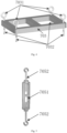
- the inertia simulation tooling includes a mounting flange, and is connected with the pointing measuring instrument through the mounting flange, and a counterweight is mounted on a side surface of the inertia simulation tooling opposite to the pointing measuring instrument.
- the quasi-zero stiffness suspension adjustment device performs a direction adjustment of six degrees of freedom such that the pointing measuring instrument faces the collimator, wherein x, y and z are defined to represent three mutually perpendicular coordinate axis directions with a center of mass of the pointing measuring instrument as an origin, z is an optical axis direction, and U,V and W represent directions of degrees of freedom for rotation around the x, y and z axes, respectively.
- three disturbance sources are mounted on three surfaces of the inertia simulation tooling, respectively, and normals of the three disturbance sources are perpendicular to each other.
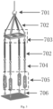
- the quasi-zero stiffness suspension adjustment device includes: a suspension crown block, high-stiffness suspenders, a -shaped tooling, a high-modulus and high-stiffness spring, a double-stroke bolt assembly and a first suspension point.
- the -shaped tooling is arranged horizontally, with four second suspension points at four corners of its upper end face and four third suspension points at four corners of its lower end face.
- the four second suspension points are respectively connected to the suspension crown block through the high-stiffness suspenders, and the four third suspension points are respectively connected to upper ends of corresponding high-modulus and high-stiffness springs under the -shaped tooling through the high-stiffness suspenders.
- Lower ends of four high-modulus and high-stiffness springs each are connected with the first suspension point through the double-stroke bolt assembly.
- a top of the inertia simulation tooling includes four hooks, which are respectively connected with four first suspension points at a lower end of the quasi-zero stiffness suspension adjustment device; and the double-stroke bolt assembly includes a two-sided nut frame and two M16 high-strength bolts.
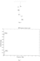
- a parameter checking method of a variable-stroke self-adaptive adjustment quasi-zero stiffness device which includes: step 1, checking a quasi-zero stiffness frequency, where according to the two-pendulum system formed by the quasi-zero stiffness suspension adjustment device, the pointing measuring instrument, the disturbance source and the inertia simulation tooling as a whole, a dynamic equation of the two-pendulum system is established and solved to obtain a characteristic frequency of the variable-stroke self-adaptive adjustment quasi-zero stiffness device, i.e.
- the dynamic equation of the two-pendulum system is established by a Lagrangue equation method, and the equation is a second-order implicit differential equation set in two variables, and is solved by a Runge-Kutta numerical solution method to obtain the characteristic frequency of the device, i.e., the stiffness value of the variable-stroke self-adaptive adjustment quasi-zero stiffness device.
- L 1 is a length of a first swing arm of the two-pendulum system
- L 2 is a length of a second swing arm of the two-pendulum system
- m 1 is an equivalent mass point of the first swing arm of the two-pendulum system
- m 2 is an equivalent mass point of the second swing arm of the two-pendulum system
- g is a gravitational acceleration
- ⁇ 1 is an included angle between the first swing arm and the gravitational acceleration g
- ⁇ 2 is an included angle between the second swing arm and the gravitational acceleration g
- two dots on ⁇ 1 and ⁇ 2 represent a second derivative.
- a finite element analysis method is used to further check the quasi-zero stiffness frequency to determine whether its transverse characteristic frequency is consistent with a theoretical calculation result.
- checking the adjustment resolution specifically includes: calculating the adjustment resolution, where the adjustment of the pointing measuring instrument in the U and V directions and the position adjustment of the target on the focal plane of the pointing measuring instrument are realized through the double-stroke bolt assembly.
- Zu represents a pitch
- L ⁇ represents an effective length of the pointing measuring instrument of the two-pendulum system in the optical axis direction
- the adjustment resolution ⁇ u should not be greater than 0.5'.
- the target is adjusted to be within a field of view of the pointing measuring instrument through the double-stroke bolt assembly.
- the present disclosure provides a variable-stroke self-adaptive adjustment quasi-zero stiffness device and a parameter checking method of the same.
- the device is configured as a two-pendulum system, and a quasi-zero stiffness condition of an on-orbit free boundary condition is simulated in a ground laboratory environment through the variable-stroke self-adaptive adjustment quasi-zero stiffness device.
- the adjustment of pitch and yaw attitudes is creatively realized when the pointing measuring instrument is suspended, so that the target is aligned in the focal plane of the pointing measuring instrument.
- the key parameters of the zero stiffness device are effectively checked to ensure that the design of the zero stiffness device meets the requirements and the indexes are reliable.
- the present disclosure can comprehensively evaluate and quantitatively analyze the influence of the platform micro-vibration environment on the spatial pointing measuring instrument with the extremely high precision.
- the integrating sphere 10, the target 20 and the collimator 30 are coaxially mounted on the optical air-bearing platform 80 in sequence.
- the integrating sphere 10 provides a light source
- the target 20 provides point target information
- the collimator 30 simulates infinity.
- the pointing measuring instrument 40 is an object to be tested
- the inertia simulation tooling 60 has a hollow cubic structure
- the pointing measuring instrument 40 is connected and fixed with the inertia simulation tooling 60 through a screw.
- Three disturbance sources 50 are mounted on the inertia simulation tooling 60 to provide small disturbance and inertia for the pointing measuring instrument 40.
- the quasi-zero stiffness suspension adjustment device 70 suspends the inertia simulation tooling 60 to provide a free boundary environment.
- the -shaped tooling 703 is arranged horizontally, with four second suspension points 7031 at four corners of its upper end face and four third suspension points 7032 at four corners of its lower end face.
- the four second suspension points 7031 are respectively connected to the suspension crown block 701 through the high-stiffness suspenders 702, and the four third suspension points 7032 are respectively connected to upper ends of corresponding high-modulus and high-stiffness springs 704 under the -shaped tooling 703 through the high-stiffness suspenders 702.
- Lower ends of the four high-modulus and high-stiffness springs 704 are respectively connected to the first suspension points 706 through the double-stroke bolt assemblies 705.
- the quasi-zero stiffness suspension adjustment device 70 suspends the inertia simulation tooling 60 to provide the free boundary environment.
- the quasi-zero stiffness suspension adjustment device 70, the pointing measuring instrument 40, the disturbance source 50 and the inertia simulation tooling 60 form a set of two-pendulum system as a whole, and the basic characteristic frequencies of the two-pendulum system are 0.114 Hz and 0.295 Hz, respectively.
- the direction adjustment of six degrees of freedom of the pointing measuring instrument 40 is realized by the quasi-zero stiffness suspension adjustment device 70, so that the center of the pointing measuring instrument 40 is aligned with the axis of the collimator 30.
- the parameter checking is divided into quasi-zero stiffness checking and strength checking.
- the quasi-zero stiffness checking is to confirm that the designed device meets the quasi-zero stiffness condition and can meet the test requirements.
- the strength checking is to ensure the safety and reliability of the system, and avoid damages and potential safety hazards.
- a variable-stroke self-adaptive adjustment quasi-zero stiffness device is configured as a two-pendulum system, a dynamic equation of the two-pendulum system is established by the Lagrangue equation method, and the equation is a second-order implicit differential equation set in two variables, and is solved by the Runge-Kutta numerical solution method to obtain the characteristic frequency of the device, that is, the stiffness value of the variable-stroke self-adaptive adjustment quasi-zero stiffness device.
- the strength checking in the present disclosure mainly lies in the strength checking of the high-modulus and high-stiffness spring to ensure safety, and the strength checking mainly uses the strength checking calculation formula of the spring to check the shear stress of the spring wire.
- the adjustment of the pointing measuring instrument in the U and V directions and the position adjustment of the target on the focal plane of the pointing measuring instrument are realized through the double-stroke bolt assembly.
Landscapes
- Engineering & Computer Science (AREA)
- Physics & Mathematics (AREA)
- Remote Sensing (AREA)
- Theoretical Computer Science (AREA)
- General Physics & Mathematics (AREA)
- Radar, Positioning & Navigation (AREA)
- General Engineering & Computer Science (AREA)
- Computer Hardware Design (AREA)
- Evolutionary Computation (AREA)
- Geometry (AREA)
- Aviation & Aerospace Engineering (AREA)
- Automation & Control Theory (AREA)
- Astronomy & Astrophysics (AREA)
- Chemical & Material Sciences (AREA)
- Analytical Chemistry (AREA)
- Testing Of Devices, Machine Parts, Or Other Structures Thereof (AREA)
- Investigating Strength Of Materials By Application Of Mechanical Stress (AREA)
Applications Claiming Priority (2)
| Application Number | Priority Date | Filing Date | Title |
|---|---|---|---|
| CN202110978217.XA CN113919190B (zh) | 2021-08-23 | 2021-08-23 | 一种变行程自适应调整准零刚度装置及参数校核方法 |
| PCT/CN2022/112709 WO2023024968A1 (zh) | 2021-08-23 | 2022-08-16 | 一种变行程自适应调整准零刚度装置及参数校核方法 |
Publications (2)
| Publication Number | Publication Date |
|---|---|
| EP4394643A1 true EP4394643A1 (de) | 2024-07-03 |
| EP4394643A4 EP4394643A4 (de) | 2025-08-20 |
Family
ID=79233160
Family Applications (1)
| Application Number | Title | Priority Date | Filing Date |
|---|---|---|---|
| EP22860314.8A Pending EP4394643A4 (de) | 2021-08-23 | 2022-08-16 | Selbstanpassende vorrichtung mit variabler hubeinstellung für quasi-nullsteifigkeit und parameterprüfverfahren |
Country Status (4)
| Country | Link |
|---|---|
| US (1) | US20240367823A1 (de) |
| EP (1) | EP4394643A4 (de) |
| CN (1) | CN113919190B (de) |
| WO (1) | WO2023024968A1 (de) |
Families Citing this family (8)
| Publication number | Priority date | Publication date | Assignee | Title |
|---|---|---|---|---|
| CN113919190B (zh) * | 2021-08-23 | 2022-06-03 | 北京控制工程研究所 | 一种变行程自适应调整准零刚度装置及参数校核方法 |
| CN114988280B (zh) * | 2022-06-02 | 2023-03-17 | 长光卫星技术股份有限公司 | 卫星地面试验柔性支撑零应力悬吊装置及悬吊方法 |
| CN116698369A (zh) * | 2023-05-29 | 2023-09-05 | 中国科学院长春光学精密机械与物理研究所 | 一种多光谱动态光学装备成像质量退化评估装置 |
| CN117284506B (zh) * | 2023-08-09 | 2024-03-08 | 南京航空航天大学 | 一种航天吸附机构微重力冲击动力学测试平台及测试方法 |
| CN117944095B (zh) * | 2024-03-25 | 2024-08-16 | 中国科学院长春光学精密机械与物理研究所 | 变力矩式可控时变刚度柔性基座 |
| CN119394562B (zh) * | 2024-12-31 | 2025-03-25 | 石家庄铁道大学 | 自由振动试验系统的调频方法 |
| CN119808598B (zh) * | 2025-03-11 | 2025-06-06 | 中南大学 | 一种基于强化学习的多级准零刚度超结构设计方法 |
| CN120971074B (zh) * | 2025-10-23 | 2026-01-06 | 华中科技大学 | 一种检验质量释放过程的六自由度地面测试装置和方法 |
Family Cites Families (19)
| Publication number | Priority date | Publication date | Assignee | Title |
|---|---|---|---|---|
| CN101839731B (zh) * | 2010-05-18 | 2012-05-23 | 浙江工业大学 | 基于双电磁力的无扰气浮磁动悬吊装置 |
| CN102650563B (zh) * | 2011-12-20 | 2015-04-08 | 北京卫星环境工程研究所 | 航天器在轨微振动地面试验系统 |
| CN103279595B (zh) * | 2013-04-27 | 2016-04-27 | 上海卫星工程研究所 | 准零刚度非线性悬吊系统设计方法 |
| CN103482088B (zh) | 2013-08-12 | 2015-07-15 | 上海卫星工程研究所 | 卫星微振动试验多点悬吊系统及其设计方法 |
| US9920793B1 (en) * | 2013-12-06 | 2018-03-20 | Hrl Laboratories, Llc | Negative stiffness system with variable preload adjustment |
| CN104386267B (zh) * | 2014-11-03 | 2016-07-06 | 哈尔滨工业大学 | 适用于空间飞行器高稳定度指向控制试验装置及方法 |
| CN105253333A (zh) * | 2015-11-23 | 2016-01-20 | 上海卫星装备研究所 | 用于航天产品地面失重状态模拟的低刚度柔性悬吊装置 |
| CN105530514A (zh) * | 2016-01-28 | 2016-04-27 | 长光卫星技术有限公司 | 一种用于卫星平台微振动对相机成像影响的测试装置 |
| CN106477074B (zh) * | 2016-11-29 | 2019-07-12 | 上海卫星装备研究所 | 一种新型航天器在轨超静失重环境模拟试验系统 |
| CN106599480A (zh) * | 2016-12-16 | 2017-04-26 | 中国科学院长春光学精密机械与物理研究所 | 一种空间相机在轨微振动仿真模型的修正方法 |
| CN107941441B (zh) * | 2017-11-14 | 2019-12-03 | 北京卫星环境工程研究所 | 确定模拟在轨边界对航天器在轨动力学特性影响的方法 |
| CN108801574B (zh) * | 2018-06-15 | 2020-06-05 | 北京卫星环境工程研究所 | 航天器高分相机光轴抖动性能的验证系统 |
| CN109540493B (zh) * | 2018-12-21 | 2019-10-25 | 东北大学 | 一种准零刚度隔振器的试验装置 |
| CN110929388A (zh) * | 2019-11-06 | 2020-03-27 | 中国科学院微小卫星创新研究院 | 一种基于精跟踪相机的飞行器振动干扰分析方法 |
| CN111207895B (zh) * | 2020-01-13 | 2022-01-07 | 中国科学院微小卫星创新研究院 | 一种遥感微纳卫星地面微振动实验系统及方法 |
| CN111157208A (zh) * | 2020-02-27 | 2020-05-15 | 广州大学 | 一种卫星微振动隔振模拟测量系统与方法 |
| CN111638721B (zh) * | 2020-04-28 | 2023-08-11 | 北京控制工程研究所 | 一种航天器三超控制全链路扰动传递验证系统及验证方法 |
| CN112504595B (zh) * | 2020-10-27 | 2022-07-05 | 北京控制工程研究所 | 一种空间指向测量仪器微振动影响测量装置及方法 |
| CN113919190B (zh) * | 2021-08-23 | 2022-06-03 | 北京控制工程研究所 | 一种变行程自适应调整准零刚度装置及参数校核方法 |
-
2021
- 2021-08-23 CN CN202110978217.XA patent/CN113919190B/zh active Active
-
2022
- 2022-08-16 EP EP22860314.8A patent/EP4394643A4/de active Pending
- 2022-08-16 WO PCT/CN2022/112709 patent/WO2023024968A1/zh not_active Ceased
- 2022-08-16 US US18/685,965 patent/US20240367823A1/en active Pending
Also Published As
| Publication number | Publication date |
|---|---|
| CN113919190B (zh) | 2022-06-03 |
| CN113919190A (zh) | 2022-01-11 |
| EP4394643A4 (de) | 2025-08-20 |
| US20240367823A1 (en) | 2024-11-07 |
| WO2023024968A1 (zh) | 2023-03-02 |
Similar Documents
| Publication | Publication Date | Title |
|---|---|---|
| EP4394643A1 (de) | Selbstanpassende vorrichtung mit variabler hubeinstellung für quasi-nullsteifigkeit und parameterprüfverfahren | |
| US12085474B2 (en) | Apparatus and method for measuring micro-vibration influence of spatial orientation measuring instrument | |
| CN108760150B (zh) | 一种大型力值对称加载力与力矩解耦校准装置 | |
| CN109141905B (zh) | 一种六分力试车台及其测量矢量推力的方法 | |
| EP2613134B1 (de) | System und verfahren zur ausrichtung eines testartikels mit einer last | |
| CN104344804B (zh) | 卫星模拟零重力状态单机指向精度测量方法 | |
| CN101226094A (zh) | 一种用于六维力传感器标定装置的标定方法 | |
| CN109188648B (zh) | 一种用于空间光学载荷地面重力卸载的浮动支撑装置 | |
| CN106405658A (zh) | 一种基于矢量磁梯度计的运动式磁性目标定位方法 | |
| CN101226095A (zh) | 六维力传感器标定装置 | |
| CN101871505A (zh) | 一种正负刚度并联三平移振动与冲击隔离平台 | |
| CN109115510B (zh) | 一种六分力试验台及其误差的确定方法 | |
| CN103616116A (zh) | 机械解耦重载并联六维测力平台 | |
| CN113029415A (zh) | 无干涉多分力固体火箭发动机推力测量系统及安装测量方法 | |
| CN109115513B (zh) | 一种六分力试车台动架固有频率的确定方法 | |
| Coppa et al. | Dynamic buckling of shell structures subject to longitudinal impact | |
| CN219302146U (zh) | 一种航天器用轨控机架静力试验装置 | |
| KR20220102926A (ko) | 베어링 유격 측정 장치 | |
| RU127464U1 (ru) | Стенд для измерения вертикальной нагрузки, воздействующей на объект авиационной техники | |
| CN114739833B (zh) | 三向可调节试验加载系统 | |
| Chai et al. | Development of a multi-component force measurement platform for vector thrust calibration of aviation engines | |
| Sankar et al. | On friction and motion accuracy in jewel bearing | |
| Zhao et al. | A micro-force measurement torsion pendulum design with dual laser detection | |
| Trim et al. | Improved Ribbon Bridge structural response validation testing | |
| Hudson et al. | Development of a differential accelerometer to test the equivalence principle in the microscope mission |
Legal Events
| Date | Code | Title | Description |
|---|---|---|---|
| STAA | Information on the status of an ep patent application or granted ep patent |
Free format text: STATUS: THE INTERNATIONAL PUBLICATION HAS BEEN MADE |
|
| PUAI | Public reference made under article 153(3) epc to a published international application that has entered the european phase |
Free format text: ORIGINAL CODE: 0009012 |
|
| STAA | Information on the status of an ep patent application or granted ep patent |
Free format text: STATUS: REQUEST FOR EXAMINATION WAS MADE |
|
| 17P | Request for examination filed |
Effective date: 20240308 |
|
| AK | Designated contracting states |
Kind code of ref document: A1 Designated state(s): AL AT BE BG CH CY CZ DE DK EE ES FI FR GB GR HR HU IE IS IT LI LT LU LV MC MK MT NL NO PL PT RO RS SE SI SK SM TR |
|
| DAV | Request for validation of the european patent (deleted) | ||
| DAX | Request for extension of the european patent (deleted) | ||
| A4 | Supplementary search report drawn up and despatched |
Effective date: 20250718 |
|
| RIC1 | Information provided on ipc code assigned before grant |
Ipc: G06F 30/23 20200101AFI20250714BHEP Ipc: G01M 13/00 20190101ALI20250714BHEP Ipc: B64G 7/00 20060101ALI20250714BHEP Ipc: F16D 7/00 20060101ALI20250714BHEP Ipc: G01M 11/04 20060101ALI20250714BHEP Ipc: G06F 30/20 20200101ALI20250714BHEP Ipc: G06F 119/14 20200101ALI20250714BHEP |