EP4394162A2 - Vorrichtung und verfahren zur schaufelverbindung - Google Patents
Vorrichtung und verfahren zur schaufelverbindung Download PDFInfo
- Publication number
- EP4394162A2 EP4394162A2 EP24176396.0A EP24176396A EP4394162A2 EP 4394162 A2 EP4394162 A2 EP 4394162A2 EP 24176396 A EP24176396 A EP 24176396A EP 4394162 A2 EP4394162 A2 EP 4394162A2
- Authority
- EP
- European Patent Office
- Prior art keywords
- airfoil
- cropped
- repair
- repair component
- electrode
- Prior art date
- Legal status (The legal status is an assumption and is not a legal conclusion. Google has not performed a legal analysis and makes no representation as to the accuracy of the status listed.)
- Granted
Links
Images







Classifications
-
- F—MECHANICAL ENGINEERING; LIGHTING; HEATING; WEAPONS; BLASTING
- F01—MACHINES OR ENGINES IN GENERAL; ENGINE PLANTS IN GENERAL; STEAM ENGINES
- F01D—NON-POSITIVE DISPLACEMENT MACHINES OR ENGINES, e.g. STEAM TURBINES
- F01D5/00—Blades; Blade-carrying members; Heating, heat-insulating, cooling or antivibration means on the blades or the members
- F01D5/005—Repairing methods or devices
-
- B—PERFORMING OPERATIONS; TRANSPORTING
- B23—MACHINE TOOLS; METAL-WORKING NOT OTHERWISE PROVIDED FOR
- B23K—SOLDERING OR UNSOLDERING; WELDING; CLADDING OR PLATING BY SOLDERING OR WELDING; CUTTING BY APPLYING HEAT LOCALLY, e.g. FLAME CUTTING; WORKING BY LASER BEAM
- B23K11/00—Resistance welding; Severing by resistance heating
- B23K11/002—Resistance welding; Severing by resistance heating specially adapted for particular articles or work
- B23K11/0026—Welding of thin articles
-
- B—PERFORMING OPERATIONS; TRANSPORTING
- B23—MACHINE TOOLS; METAL-WORKING NOT OTHERWISE PROVIDED FOR
- B23K—SOLDERING OR UNSOLDERING; WELDING; CLADDING OR PLATING BY SOLDERING OR WELDING; CUTTING BY APPLYING HEAT LOCALLY, e.g. FLAME CUTTING; WORKING BY LASER BEAM
- B23K11/00—Resistance welding; Severing by resistance heating
- B23K11/16—Resistance welding; Severing by resistance heating taking account of the properties of the material to be welded
-
- B—PERFORMING OPERATIONS; TRANSPORTING
- B23—MACHINE TOOLS; METAL-WORKING NOT OTHERWISE PROVIDED FOR
- B23K—SOLDERING OR UNSOLDERING; WELDING; CLADDING OR PLATING BY SOLDERING OR WELDING; CUTTING BY APPLYING HEAT LOCALLY, e.g. FLAME CUTTING; WORKING BY LASER BEAM
- B23K15/00—Electron-beam welding or cutting
- B23K15/0006—Electron-beam welding or cutting specially adapted for particular articles or work
-
- B—PERFORMING OPERATIONS; TRANSPORTING
- B23—MACHINE TOOLS; METAL-WORKING NOT OTHERWISE PROVIDED FOR
- B23K—SOLDERING OR UNSOLDERING; WELDING; CLADDING OR PLATING BY SOLDERING OR WELDING; CUTTING BY APPLYING HEAT LOCALLY, e.g. FLAME CUTTING; WORKING BY LASER BEAM
- B23K15/00—Electron-beam welding or cutting
- B23K15/0046—Welding
- B23K15/0053—Seam welding
- B23K15/006—Seam welding of rectilinear seams
-
- B—PERFORMING OPERATIONS; TRANSPORTING
- B23—MACHINE TOOLS; METAL-WORKING NOT OTHERWISE PROVIDED FOR
- B23K—SOLDERING OR UNSOLDERING; WELDING; CLADDING OR PLATING BY SOLDERING OR WELDING; CUTTING BY APPLYING HEAT LOCALLY, e.g. FLAME CUTTING; WORKING BY LASER BEAM
- B23K15/00—Electron-beam welding or cutting
- B23K15/0046—Welding
- B23K15/0093—Welding characterised by the properties of the materials to be welded
-
- B—PERFORMING OPERATIONS; TRANSPORTING
- B23—MACHINE TOOLS; METAL-WORKING NOT OTHERWISE PROVIDED FOR
- B23P—METAL-WORKING NOT OTHERWISE PROVIDED FOR; COMBINED OPERATIONS; UNIVERSAL MACHINE TOOLS
- B23P6/00—Restoring or reconditioning objects
- B23P6/002—Repairing turbine components, e.g. moving or stationary blades, rotors
-
- F—MECHANICAL ENGINEERING; LIGHTING; HEATING; WEAPONS; BLASTING
- F01—MACHINES OR ENGINES IN GENERAL; ENGINE PLANTS IN GENERAL; STEAM ENGINES
- F01D—NON-POSITIVE DISPLACEMENT MACHINES OR ENGINES, e.g. STEAM TURBINES
- F01D5/00—Blades; Blade-carrying members; Heating, heat-insulating, cooling or antivibration means on the blades or the members
- F01D5/02—Blade-carrying members, e.g. rotors
-
- F—MECHANICAL ENGINEERING; LIGHTING; HEATING; WEAPONS; BLASTING
- F01—MACHINES OR ENGINES IN GENERAL; ENGINE PLANTS IN GENERAL; STEAM ENGINES
- F01D—NON-POSITIVE DISPLACEMENT MACHINES OR ENGINES, e.g. STEAM TURBINES
- F01D5/00—Blades; Blade-carrying members; Heating, heat-insulating, cooling or antivibration means on the blades or the members
- F01D5/12—Blades
- F01D5/14—Form or construction
- F01D5/141—Shape, i.e. outer, aerodynamic form
-
- F—MECHANICAL ENGINEERING; LIGHTING; HEATING; WEAPONS; BLASTING
- F01—MACHINES OR ENGINES IN GENERAL; ENGINE PLANTS IN GENERAL; STEAM ENGINES
- F01D—NON-POSITIVE DISPLACEMENT MACHINES OR ENGINES, e.g. STEAM TURBINES
- F01D5/00—Blades; Blade-carrying members; Heating, heat-insulating, cooling or antivibration means on the blades or the members
- F01D5/12—Blades
- F01D5/14—Form or construction
- F01D5/147—Construction, i.e. structural features, e.g. of weight-saving hollow blades
-
- F—MECHANICAL ENGINEERING; LIGHTING; HEATING; WEAPONS; BLASTING
- F01—MACHINES OR ENGINES IN GENERAL; ENGINE PLANTS IN GENERAL; STEAM ENGINES
- F01D—NON-POSITIVE DISPLACEMENT MACHINES OR ENGINES, e.g. STEAM TURBINES
- F01D5/00—Blades; Blade-carrying members; Heating, heat-insulating, cooling or antivibration means on the blades or the members
- F01D5/30—Fixing blades to rotors; Blade roots ; Blade spacers
-
- F—MECHANICAL ENGINEERING; LIGHTING; HEATING; WEAPONS; BLASTING
- F01—MACHINES OR ENGINES IN GENERAL; ENGINE PLANTS IN GENERAL; STEAM ENGINES
- F01D—NON-POSITIVE DISPLACEMENT MACHINES OR ENGINES, e.g. STEAM TURBINES
- F01D5/00—Blades; Blade-carrying members; Heating, heat-insulating, cooling or antivibration means on the blades or the members
- F01D5/34—Rotor-blade aggregates of unitary construction, e.g. formed of sheet laminae
-
- F—MECHANICAL ENGINEERING; LIGHTING; HEATING; WEAPONS; BLASTING
- F04—POSITIVE - DISPLACEMENT MACHINES FOR LIQUIDS; PUMPS FOR LIQUIDS OR ELASTIC FLUIDS
- F04D—NON-POSITIVE-DISPLACEMENT PUMPS
- F04D29/00—Details, component parts, or accessories
- F04D29/26—Rotors specially for elastic fluids
- F04D29/32—Rotors specially for elastic fluids for axial flow pumps
- F04D29/321—Rotors specially for elastic fluids for axial flow pumps for axial flow compressors
- F04D29/324—Blades
-
- B—PERFORMING OPERATIONS; TRANSPORTING
- B23—MACHINE TOOLS; METAL-WORKING NOT OTHERWISE PROVIDED FOR
- B23K—SOLDERING OR UNSOLDERING; WELDING; CLADDING OR PLATING BY SOLDERING OR WELDING; CUTTING BY APPLYING HEAT LOCALLY, e.g. FLAME CUTTING; WORKING BY LASER BEAM
- B23K2101/00—Articles made by soldering, welding or cutting
- B23K2101/001—Turbines
-
- B—PERFORMING OPERATIONS; TRANSPORTING
- B23—MACHINE TOOLS; METAL-WORKING NOT OTHERWISE PROVIDED FOR
- B23K—SOLDERING OR UNSOLDERING; WELDING; CLADDING OR PLATING BY SOLDERING OR WELDING; CUTTING BY APPLYING HEAT LOCALLY, e.g. FLAME CUTTING; WORKING BY LASER BEAM
- B23K2103/00—Materials to be soldered, welded or cut
- B23K2103/18—Dissimilar materials
- B23K2103/26—Alloys of Nickel and Cobalt and Chromium
-
- B—PERFORMING OPERATIONS; TRANSPORTING
- B23—MACHINE TOOLS; METAL-WORKING NOT OTHERWISE PROVIDED FOR
- B23P—METAL-WORKING NOT OTHERWISE PROVIDED FOR; COMBINED OPERATIONS; UNIVERSAL MACHINE TOOLS
- B23P2700/00—Indexing scheme relating to the articles being treated, e.g. manufactured, repaired, assembled, connected or other operations covered in the subgroups
- B23P2700/13—Parts of turbine combustion chambers
-
- F—MECHANICAL ENGINEERING; LIGHTING; HEATING; WEAPONS; BLASTING
- F05—INDEXING SCHEMES RELATING TO ENGINES OR PUMPS IN VARIOUS SUBCLASSES OF CLASSES F01-F04
- F05D—INDEXING SCHEME FOR ASPECTS RELATING TO NON-POSITIVE-DISPLACEMENT MACHINES OR ENGINES, GAS-TURBINES OR JET-PROPULSION PLANTS
- F05D2230/00—Manufacture
- F05D2230/20—Manufacture essentially without removing material
- F05D2230/23—Manufacture essentially without removing material by permanently joining parts together
- F05D2230/232—Manufacture essentially without removing material by permanently joining parts together by welding
-
- F—MECHANICAL ENGINEERING; LIGHTING; HEATING; WEAPONS; BLASTING
- F05—INDEXING SCHEMES RELATING TO ENGINES OR PUMPS IN VARIOUS SUBCLASSES OF CLASSES F01-F04
- F05D—INDEXING SCHEME FOR ASPECTS RELATING TO NON-POSITIVE-DISPLACEMENT MACHINES OR ENGINES, GAS-TURBINES OR JET-PROPULSION PLANTS
- F05D2230/00—Manufacture
- F05D2230/20—Manufacture essentially without removing material
- F05D2230/23—Manufacture essentially without removing material by permanently joining parts together
- F05D2230/232—Manufacture essentially without removing material by permanently joining parts together by welding
- F05D2230/233—Electron beam welding
-
- F—MECHANICAL ENGINEERING; LIGHTING; HEATING; WEAPONS; BLASTING
- F05—INDEXING SCHEMES RELATING TO ENGINES OR PUMPS IN VARIOUS SUBCLASSES OF CLASSES F01-F04
- F05D—INDEXING SCHEME FOR ASPECTS RELATING TO NON-POSITIVE-DISPLACEMENT MACHINES OR ENGINES, GAS-TURBINES OR JET-PROPULSION PLANTS
- F05D2230/00—Manufacture
- F05D2230/20—Manufacture essentially without removing material
- F05D2230/23—Manufacture essentially without removing material by permanently joining parts together
- F05D2230/232—Manufacture essentially without removing material by permanently joining parts together by welding
- F05D2230/234—Laser welding
-
- F—MECHANICAL ENGINEERING; LIGHTING; HEATING; WEAPONS; BLASTING
- F05—INDEXING SCHEMES RELATING TO ENGINES OR PUMPS IN VARIOUS SUBCLASSES OF CLASSES F01-F04
- F05D—INDEXING SCHEME FOR ASPECTS RELATING TO NON-POSITIVE-DISPLACEMENT MACHINES OR ENGINES, GAS-TURBINES OR JET-PROPULSION PLANTS
- F05D2230/00—Manufacture
- F05D2230/20—Manufacture essentially without removing material
- F05D2230/23—Manufacture essentially without removing material by permanently joining parts together
- F05D2230/232—Manufacture essentially without removing material by permanently joining parts together by welding
- F05D2230/235—TIG or MIG welding
-
- F—MECHANICAL ENGINEERING; LIGHTING; HEATING; WEAPONS; BLASTING
- F05—INDEXING SCHEMES RELATING TO ENGINES OR PUMPS IN VARIOUS SUBCLASSES OF CLASSES F01-F04
- F05D—INDEXING SCHEME FOR ASPECTS RELATING TO NON-POSITIVE-DISPLACEMENT MACHINES OR ENGINES, GAS-TURBINES OR JET-PROPULSION PLANTS
- F05D2230/00—Manufacture
- F05D2230/40—Heat treatment
-
- F—MECHANICAL ENGINEERING; LIGHTING; HEATING; WEAPONS; BLASTING
- F05—INDEXING SCHEMES RELATING TO ENGINES OR PUMPS IN VARIOUS SUBCLASSES OF CLASSES F01-F04
- F05D—INDEXING SCHEME FOR ASPECTS RELATING TO NON-POSITIVE-DISPLACEMENT MACHINES OR ENGINES, GAS-TURBINES OR JET-PROPULSION PLANTS
- F05D2230/00—Manufacture
- F05D2230/80—Repairing, retrofitting or upgrading methods
-
- F—MECHANICAL ENGINEERING; LIGHTING; HEATING; WEAPONS; BLASTING
- F05—INDEXING SCHEMES RELATING TO ENGINES OR PUMPS IN VARIOUS SUBCLASSES OF CLASSES F01-F04
- F05D—INDEXING SCHEME FOR ASPECTS RELATING TO NON-POSITIVE-DISPLACEMENT MACHINES OR ENGINES, GAS-TURBINES OR JET-PROPULSION PLANTS
- F05D2250/00—Geometry
- F05D2250/10—Two-dimensional
- F05D2250/18—Two-dimensional patterned
- F05D2250/183—Two-dimensional patterned zigzag
-
- F—MECHANICAL ENGINEERING; LIGHTING; HEATING; WEAPONS; BLASTING
- F05—INDEXING SCHEMES RELATING TO ENGINES OR PUMPS IN VARIOUS SUBCLASSES OF CLASSES F01-F04
- F05D—INDEXING SCHEME FOR ASPECTS RELATING TO NON-POSITIVE-DISPLACEMENT MACHINES OR ENGINES, GAS-TURBINES OR JET-PROPULSION PLANTS
- F05D2270/00—Control
- F05D2270/80—Devices generating input signals, e.g. transducers, sensors, cameras or strain gauges
-
- F—MECHANICAL ENGINEERING; LIGHTING; HEATING; WEAPONS; BLASTING
- F05—INDEXING SCHEMES RELATING TO ENGINES OR PUMPS IN VARIOUS SUBCLASSES OF CLASSES F01-F04
- F05D—INDEXING SCHEME FOR ASPECTS RELATING TO NON-POSITIVE-DISPLACEMENT MACHINES OR ENGINES, GAS-TURBINES OR JET-PROPULSION PLANTS
- F05D2270/00—Control
- F05D2270/80—Devices generating input signals, e.g. transducers, sensors, cameras or strain gauges
- F05D2270/804—Optical devices
- F05D2270/8041—Cameras
Definitions
- Typical aircraft propulsion systems include one or more gas turbine engines, which each generally include a turbomachine.
- the turbomachine includes, in serial flow order, a compressor section, a combustion section, a turbine section, and an exhaust section.
- air is provided to an inlet of the compressor section where one or more axial compressors progressively compress the air until it reaches the combustion section.
- Fuel is mixed with the compressed air and burned within the combustion section to provide combustion gases.
- the combustion gases are routed from the combustion section to the turbine section.
- the flow of combustion gases through the turbine section drives the turbine section and is then routed through the exhaust section, e.g., to atmosphere.
- first,” second, and third may be used interchangeably to distinguish one component from another and are not intended to signify location or importance of the individual components.
- forward and aft refer to relative positions within a gas turbine engine or vehicle and refer to the normal operational attitude of the gas turbine engine or vehicle.
- forward refers to a position closer to an engine inlet and aft refers to a position closer to an engine nozzle or exhaust.
- upstream and downstream refer to the relative direction with respect to fluid flow in a fluid pathway.
- upstream refers to the direction from which the fluid flows
- downstream refers to the direction to which the fluid flows.
- Coupled refers to both direct coupling, fixing, or attaching, as well as indirect coupling, fixing, or attaching through one or more intermediate components or features, unless otherwise specified herein.
- Approximating language is applied to modify any quantitative representation that could permissibly vary without resulting in a change in the basic function to which it is related. Accordingly, a value modified by a term or terms, such as “about,” “approximately,” and “substantially,” are not to be limited to the precise value specified. In at least some instances, the approximating language may correspond to the precision of an instrument for measuring the value, or the precision of the methods or machines for constructing or manufacturing the components and/or systems. The approximating language may refer to being within a +/- 1, 2, 4, 10, 15, or 20 percent margin in either individual values, range(s) of values, and/or endpoints defining range(s) of values.
- a typical compressor has multiple stages or rows of rotor blades and corresponding stator vanes that sequentially increase the pressure of the air as it flows in an axial downstream direction.
- the compressor blades include dovetails for being removably mounted in a corresponding dovetail slot in the perimeter of a rotor disk.
- the dovetail-to-dovetail slot configuration permits the individual manufacture of each blade, and the individual replacement thereof in the event of blade damage during operation. However, it can be expensive to completely replace damaged blades, particularly when the damage is located near the tip of the blade such that a majority of the blade and the dovetail remains intact and undamaged.
- the present subject matter provides methods and apparatus for airfoil repairs.
- the present subject matter provides methods and apparatus for removing a damaged portion of an airfoil to form a cropped airfoil and joining an airfoil repair component to the cropped airfoil to repair the airfoil.
- Such airfoil repairs can be time-consuming and/or expensive, while often also having low yield rates, but the methods and apparatus described herein can improve success and yield while reducing repair time and costs for repair of individual airfoils, e.g., airfoils secured to a disk via a dovetail, and/or integral airfoils, e.g., blisk airfoils that are integrally formed with a disk.
- a locally or wholly oversized airfoil repair component can improve the chances of proper alignment between the airfoil repair component and the cropped airfoil (i.e., an airfoil with a damaged portion removed), with increased material margin or stock for post-joining processing to achieve the net shape of the original airfoil.
- the present subject matter provides an electrode assembly comprising a repair component electrode and a cropped airfoil electrode, which surround the airfoil repair component and the cropped airfoil, respectively, and are positioned to align the airfoil repair component with the cropped airfoil such that when a current is passed therethrough under an applied force, the airfoil repair component is attached to the cropped airfoil.
- FIG. 1 is a schematic view of an airfoil 100, e.g., an airfoil of a gas turbine engine.
- FIG. 2 is a schematic view of a bladed disk 122, also known as a blisk, having a plurality of airfoils 100 integrally formed with a rotor disk, such as may be used in a gas turbine engine.
- the gas turbine engine may be a turbofan jet engine including a fan section and a core turbine engine disposed downstream from the fan section.
- the airfoil 100 includes a concave pressure side 102 opposite a convex suction side 104. Opposite pressure side 102 and suction side 104 of the airfoil 100 extend radially along a span S from a root 106 to a tip 108 at the radially outermost portion of the airfoil 100. That is, the root 106 defines a first radial extremity of the airfoil 100, and the tip 108 defines a second radial extremity of the airfoil 100, with the root 106 and the tip 108 spaced apart along a radial direction R.
- FIG. 2 depicts a bladed disk or blisk 122 that has multiple airfoils 100 extending from a rotor disk 124 at an integral platform 126.
- the airfoils 100 of the blisk 122 are configured as described with respect to FIG. 1 .
- the blisk 122 comprises a single platform 126 that serves as a platform for each of the multiple airfoils 100.
- no dovetails 120 are necessary in the embodiment of FIG. 2 because the airfoils 100 are integrally formed with the rotor disk 124. As such, while the airfoils 100 of FIG.
- the damaged area 128 hinders the functionality of the airfoil 100 such that the airfoil 100 should be repaired.
- the airfoil 100 could be repaired by replacing the entire airfoil 100 or through removal and replacement of a portion 130 of the airfoil 100 containing the damaged area 128, which is referred to herein as the damaged portion 130.
- the damaged portion 130 may be removed along a plane below or radially inward with respect to the section line SL ( FIG. 1 ), such that more than half of the airfoil 100 is removed.
- the damaged portion 130 may be removed along a plane above or radially outward with respect to the section line SL, such that less than half of the airfoil 100 is removed.
- replacing the entire airfoil 100 generally is more expensive than replacing only the damaged portion 130 of the airfoil 100. Further, at least for the blisk 122, replacing the entire airfoil 100 generally involves a complicated manufacturing process and could risk damaging the platform 126 and/or rotor disk 124 of the blisk 122, as well as adjacent, undamaged airfoils 100. Other complications of replacing the entire airfoil 100 may be realized as well.
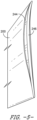
- the airfoil repair component 200 comprises a body 205 having a first side opposite a second side, with the first and second sides being either of the repair pressure side 202 and the repair suction side 204, and the first and second sides extend axially between a first edge and a second edge, with the first and second edges being either of the repair leading edge 210 and the repair trailing edge 212.
- the airfoil repair component 200 has a radial height that is less than the span S of the airfoil 100 ( FIG. 1 ).
- the repair attachment section 242 is oversized with respect to the cropped airfoil attachment section 142.
- the repair attachment section 242 has a repair chord length c r longer than a cropped chord length c c of the cropped airfoil attachment section 142, i.e., the repair chord length longer c r than a cropped chord length c c of the cropped airfoil attachment section 142.
- the repair chord length c r extends along the axial direction A from the repair leading edge 210 to the repair trailing edge 212 (or from the component first edge to the component second edge), and the cropped chord length c c extends along the axial direction A from the cropped leading edge 110c to the cropped trailing edge 112c (or from the cropped first edge to the cropped second edge).
- the width of each airfoil section is measured along the circumferential direction C, from the pressure side to the suction side.
- the repair width w r extends from the repair pressure side 202 to the repair suction side 204 (or between the component first side and component second side of the airfoil repair component 200), and the cropped width w c extends along the circumferential C from the cropped pressure side 102c to the cropped suction side 104c (or between the cropped first side and the cropped second side of the cropped airfoil 140).
- At least the repair attachment section 242 of the airfoil repair component 200 is oversized with respect to the cropped airfoil attachment section 142 of the cropped airfoil 140 such that the repair attachment section 242 extends beyond the cropped airfoil attachment section 142 axially or chordwise as well as circumferentially or widthwise.
- the oversized repair attachment section 242 defines a flared extension of the body 205. As shown in FIGS. 3A and 3B , the repair attachment section 242 flares outward from the body 205, with the repair width w r of the repair attachment section 242 wider than a body width w b of the body 205.
- the flared or oversized repair attachment section 242 provides a larger repair joining face 244 than would be defined by a remainder of the body 205, which provides a larger surface to align with the cropped joining face 144 that can help in aligning or positioning the airfoil repair component 200 with the cropped airfoil 140.
- an airfoil repair component 200 that is enlarged or oversized overall (instead of a locally enlarged/oversized airfoil repair component 200) may be used to repair a damaged airfoil 100 of a blisk 122 because there is less room to observe/detect and ensure the alignment of the airfoil repair component 200 with the cropped airfoil 140 on a blisk 122 because other airfoils 100 are adjacent the cropped airfoil 140.
- the repair joining face 244 and the cropped joining face 144 interface in a plane-to-plane interaction. Stated differently, there is plane-to-plane contact between the airfoil repair component 200 and the cropped airfoil 140. This interaction is designed to minimize the influence of alignment inaccuracies and counteract joining-induced stresses.
- the repair joining face 244 and the cropped joining face 144 are consumed in the welding process as the two components are joined together.
- the straight or linear cropped airfoil attachment section 142 and/or repair attachment section 242 are consumed during the joining process, e.g., as the airfoil repair component 200 is welded to the cropped airfoil 140, such that the airfoil geometry that is modified to remove or be without the twist disappears during the joining process, leaving the repaired airfoil 100 with only the twist of the original airfoil 100.
- a solid state resistance welding (SSRW) technique may be used to weld the airfoil repair component 200 to the cropped airfoil 140 by passing electrical current through the airfoil repair component 200 and the cropped airfoil 140 while the repair joining face 244 is in contact with (or is interfacing with) the cropped joining face 144; the repair component electrode 304 and cropped airfoil electrode 306 also can provide a compressive axial force, e.g., toward the end of the current pulses, to help weld the airfoil repair component 200 and cropped airfoil 140.
- Other welding or joining techniques or processes may be used as well.
- the dovetail block 308 defines a dovetail opening 314 having a shape complementary to the shape of the dovetail 120, and the dovetail 120 is received in the complementary shaped dovetail opening 314 of the dovetail block 308.
- the dovetail block 308 helps secure and/or stabilize the cropped airfoil 140 within the cropped airfoil electrode 306 and constrains the cropped airfoil 140 along a stacking axis As ( FIG. 6 ) or along any longitudinal orientation where stabilization is beneficial to the joining process.
- the dovetail block 308 may or may not be constrained with respect to the cropped airfoil electrode 306.
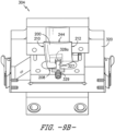
- the repair component electrode insert 330 engages both the leading edge and trailing edge profiles of the airfoil repair component 200. That is, the repair component electrode insert 330 is shaped such that an inner surface 340 of the repair component electrode insert 330 engages both the repair leading edge 210 and the repair trailing edge 212. Further, the repair component electrode insert 330 includes a leading edge guide 331a and a trailing edge guide 331b.
- the leading and trailing edge guides 331a, 331b are minimally conductive, high temperature and wear resistant guides that help stabilize the relatively thin edges of the airfoil repair component 200, e.g., in titanium airfoil repair applications.
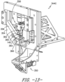
- the alignment assembly 346 includes a first rotatable knob 348a, which adjusts the position of the airfoil repair component 200 along a first degree of freedom, the axial direction A or chordwise along the cropped airfoil 140; a second rotatable knob 348b, which adjusts the position of the airfoil repair component 200 along a second degree of freedom, the circumferential direction C or widthwise along the cropped airfoil 140; and a third rotatable knob 348c, which adjusts the position of the airfoil repair component 200 with respect to a third degree of freedom, the stacking axis As.
- the hoop clamp 356 extends about the hydraulic clamp assembly 358 and is free to slide within the frame 354, and the hydraulic cylinder 362 is supported by the frame 354.
- the hoop clamp 356 applies an enclosed structural loop of squeezing force to reduce or eliminate bending stress from the frame 354 and other interrelated tooling components.
- the tooling assembly 344 decouples the holding elements from the electrodes to help eliminate the bending moment on the cropped airfoil 140 and airfoil repair component 200.
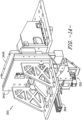
- the cropped airfoil portion 344C of the tooling assembly 344 can help stabilize the cropped airfoil electrode 306 and help ensure contact between the cropped airfoil 140 and the cropped airfoil electrode 306. Additionally, the cropped airfoil portion 344C of the tooling assembly 344 helps align the airfoil repair component 200 with the blisk 122 and its cropped airfoil 140, e.g., as shown in FIG. 14 .
- a method 1500 of repairing an airfoil 100 comprises (1502) removing a damaged portion 130 of the airfoil 100 to form a cropped airfoil 140.
- the damaged portion 130 may include a damaged area 128, which is a hollow area or cavity such as an opening, crack, gap, aperture, hole, etc. in the airfoil 100.
- the airfoil 100 may include a section line SL, which may be, e.g., one half of the distance between the tip 108 at the leading edge and a leading edge fillet tangency T.
- the damaged portion 130 (including the damaged area 128) may be removed above, below, or at (or radially outward from, radially inward from, or at) the section line SL.
- the method 1500 also may comprise (1514) obtaining a net shape finished part from the repaired airfoil 100.
- the method 1500 may include post-joining processing to achieve the net shape of the original airfoil 100 from the repaired airfoil 100.
- the repaired airfoil 100 including the airfoil repair component 200, may be machined (e.g., milled or the like) to obtain the net shape of the original airfoil 100.
- the repair component electrode comprises a point constraint, a line constraint, and a planar restraint with respect to the airfoil repair component, and wherein the point constraint is configured to be manipulated to release the airfoil repair component for removal from the repair component electrode.
- passing current through the cropped airfoil electrode and the repair component electrode comprises welding the airfoil repair component to the cropped airfoil through solid state resistance welding.
- the cropped airfoil comprises a dovetail configured to be received within a complementarily shaped dovetail slot in a rotor disk.
- the airfoil repair system of any preceding clause further comprising a cropped airfoil electrode for receipt of the cropped airfoil.
- the feedback device comprises at least one camera.
- the feedback device comprises at least one measurement gage.
- a method of repairing an airfoil comprising disposing a cropped airfoil in a cropped airfoil electrode; disposing an airfoil repair component within a repair component electrode, the repair component electrode comprising a repair component electrode insert removably received within a repair component electrode body; positioning the airfoil repair component with respect to the cropped airfoil; and conducting a joining process to attach the airfoil repair component to the cropped airfoil and form an airfoil.
- conducting a joining process comprises passing a current through the cropped airfoil electrode and the repair component electrode.
Landscapes
- Engineering & Computer Science (AREA)
- Mechanical Engineering (AREA)
- General Engineering & Computer Science (AREA)
- Ceramic Engineering (AREA)
- Chemical & Material Sciences (AREA)
- Materials Engineering (AREA)
- Architecture (AREA)
- Physics & Mathematics (AREA)
- Fluid Mechanics (AREA)
- Structures Of Non-Positive Displacement Pumps (AREA)
- Turbine Rotor Nozzle Sealing (AREA)
Priority Applications (1)
| Application Number | Priority Date | Filing Date | Title |
|---|---|---|---|
| EP25187809.6A EP4606993A3 (de) | 2021-11-18 | 2022-11-14 | Schaufelverbindungsvorrichtung |
Applications Claiming Priority (2)
| Application Number | Priority Date | Filing Date | Title |
|---|---|---|---|
| US17/529,656 US11828190B2 (en) | 2021-11-18 | 2021-11-18 | Airfoil joining apparatus and methods |
| EP22207304.1A EP4183977B1 (de) | 2021-11-18 | 2022-11-14 | Vorrichtung zur schaufelverbindung |
Related Parent Applications (2)
| Application Number | Title | Priority Date | Filing Date |
|---|---|---|---|
| EP22207304.1A Division EP4183977B1 (de) | 2021-11-18 | 2022-11-14 | Vorrichtung zur schaufelverbindung |
| EP22207304.1A Division-Into EP4183977B1 (de) | 2021-11-18 | 2022-11-14 | Vorrichtung zur schaufelverbindung |
Related Child Applications (2)
| Application Number | Title | Priority Date | Filing Date |
|---|---|---|---|
| EP25187809.6A Division EP4606993A3 (de) | 2021-11-18 | 2022-11-14 | Schaufelverbindungsvorrichtung |
| EP25187809.6A Division-Into EP4606993A3 (de) | 2021-11-18 | 2022-11-14 | Schaufelverbindungsvorrichtung |
Publications (3)
| Publication Number | Publication Date |
|---|---|
| EP4394162A2 true EP4394162A2 (de) | 2024-07-03 |
| EP4394162A3 EP4394162A3 (de) | 2024-10-23 |
| EP4394162B1 EP4394162B1 (de) | 2025-08-27 |
Family
ID=84332179
Family Applications (3)
| Application Number | Title | Priority Date | Filing Date |
|---|---|---|---|
| EP22207304.1A Active EP4183977B1 (de) | 2021-11-18 | 2022-11-14 | Vorrichtung zur schaufelverbindung |
| EP25187809.6A Pending EP4606993A3 (de) | 2021-11-18 | 2022-11-14 | Schaufelverbindungsvorrichtung |
| EP24176396.0A Active EP4394162B1 (de) | 2021-11-18 | 2022-11-14 | Vorrichtung und verfahren zur schaufelverbindung |
Family Applications Before (2)
| Application Number | Title | Priority Date | Filing Date |
|---|---|---|---|
| EP22207304.1A Active EP4183977B1 (de) | 2021-11-18 | 2022-11-14 | Vorrichtung zur schaufelverbindung |
| EP25187809.6A Pending EP4606993A3 (de) | 2021-11-18 | 2022-11-14 | Schaufelverbindungsvorrichtung |
Country Status (3)
| Country | Link |
|---|---|
| US (3) | US11828190B2 (de) |
| EP (3) | EP4183977B1 (de) |
| CN (1) | CN116136182A (de) |
Families Citing this family (2)
| Publication number | Priority date | Publication date | Assignee | Title |
|---|---|---|---|---|
| US11828190B2 (en) | 2021-11-18 | 2023-11-28 | General Electric Company | Airfoil joining apparatus and methods |
| CN116441696B (zh) * | 2023-06-19 | 2023-09-15 | 中国航发成都发动机有限公司 | 一种航空发动机静子组件真空电子束焊接方法及夹装装置 |
Family Cites Families (85)
| Publication number | Priority date | Publication date | Assignee | Title |
|---|---|---|---|---|
| US3770933A (en) | 1972-04-24 | 1973-11-06 | Nasa | Apparatus for welding blades to rotors |
| DE2319994A1 (de) | 1973-04-19 | 1974-11-07 | Motoren Turbinen Union | Schweissverfahren zur befestigung von schaufeln auf turbinenscheiben |
| US4883216A (en) * | 1988-03-28 | 1989-11-28 | General Electric Company | Method for bonding an article projection |
| US4873751A (en) | 1988-12-27 | 1989-10-17 | United Technologies Corporation | Fabrication or repair technique for integrally bladed rotor assembly |
| US4991391A (en) * | 1989-01-27 | 1991-02-12 | Westinghouse Electric Corp. | System for cooling in a gas turbine |
| US5197191A (en) | 1991-03-04 | 1993-03-30 | General Electric Company | Repair of airfoil edges |
| US5197190A (en) | 1991-03-04 | 1993-03-30 | United Technologies Corporation | Fabrication of repair method for an integrally bladed rotor |
| US5109606A (en) * | 1991-03-04 | 1992-05-05 | United Technologies Corporation | Integrally bladed rotor fabrication or repair |
| US6173327B1 (en) | 1996-07-11 | 2001-01-09 | Jeroen De Borst | Object-oriented method and apparatus for information delivery |
| GB9713395D0 (en) | 1997-06-25 | 1997-08-27 | Rolls Royce Plc | Improvements in or relating to the friction welding of components |
| US6236585B1 (en) | 1998-05-13 | 2001-05-22 | Texas Instruments Incorporated | Dynamic, data-precharged, variable-entry-length, content addressable memory circuit architecture with multiple transistor threshold voltage extensions |
| US6172327B1 (en) | 1998-07-14 | 2001-01-09 | General Electric Company | Method for laser twist welding of compressor blisk airfoils |
| US6326585B1 (en) | 1998-07-14 | 2001-12-04 | General Electric Company | Apparatus for laser twist weld of compressor blisks airfoils |
| DE19831736C2 (de) * | 1998-07-15 | 2000-05-31 | Mtu Muenchen Gmbh | Verfahren zur Reparatur und Herstellung eines integral beschaufelten Rotors für eine Strömungsmaschine |
| DE19858702B4 (de) * | 1998-12-18 | 2004-07-01 | Mtu Aero Engines Gmbh | Verfahren zum Verbinden von Schaufelteilen einer Gasturbine, sowie Schaufel und Rotor für eine Gasturbine |
| US6238187B1 (en) * | 1999-10-14 | 2001-05-29 | Lsp Technologies, Inc. | Method using laser shock peening to process airfoil weld repairs pertaining to blade cut and weld techniques |
| US6375421B1 (en) | 2000-01-31 | 2002-04-23 | General Electric Company | Piggyback rotor blisk |
| US6568077B1 (en) | 2000-05-11 | 2003-05-27 | General Electric Company | Blisk weld repair |
| US6478545B2 (en) * | 2001-03-07 | 2002-11-12 | General Electric Company | Fluted blisk |
| US6532656B1 (en) | 2001-10-10 | 2003-03-18 | General Electric Company | Gas turbine engine compressor blade restoration method |
| MY137246A (en) | 2002-04-30 | 2009-01-30 | Jfe Steel Corp | Method and instrument for measuring bead cutting shape of electric welded tube |
| US6666653B1 (en) | 2002-05-30 | 2003-12-23 | General Electric Company | Inertia welding of blades to rotors |
| US6884975B2 (en) | 2002-11-12 | 2005-04-26 | The Boeing Company | Localized stress relief by induction heating |
| US6915236B2 (en) | 2002-11-22 | 2005-07-05 | General Electric Company | Method and system for automated repair design of damaged blades of a compressor or turbine |
| US6964557B2 (en) | 2003-02-03 | 2005-11-15 | General Electric Company | Methods and apparatus for coupling a component to a turbine engine blade |
| US6933459B2 (en) | 2003-02-03 | 2005-08-23 | General Electric Company | Methods and apparatus for fabricating a turbine engine blade |
| DE10316966A1 (de) | 2003-04-12 | 2004-10-28 | Rolls-Royce Deutschland Ltd & Co Kg | Verfahren zum Wiederaufbauen flächig ausgebildeter beschädigter Bauteile |
| DE10319494A1 (de) | 2003-04-30 | 2004-11-18 | Mtu Aero Engines Gmbh | Verfahren zur Reparatur und/oder Modifikation von Bauteilen einer Gasturbine |
| DE10336587A1 (de) | 2003-08-08 | 2005-02-24 | Mtu Aero Engines Gmbh | Laufschaufel für Gasturbinenrotoren und Verfahren zur Herstellung von Gasturbinenrotoren mit integraler Beschaufelung |
| US20050091848A1 (en) * | 2003-11-03 | 2005-05-05 | Nenov Krassimir P. | Turbine blade and a method of manufacturing and repairing a turbine blade |
| US20050102835A1 (en) | 2003-11-14 | 2005-05-19 | Trewiler Gary E. | Method for repairing gas turbine rotor blades |
| US8516674B2 (en) * | 2003-11-14 | 2013-08-27 | General Electric Company | Solid state resistance welding for airfoil repair and manufacture |
| GB0327552D0 (en) | 2003-11-27 | 2003-12-31 | Rolls Royce Plc | A method of fabricating or repairing an assembly |
| DE10356679A1 (de) | 2003-11-28 | 2005-07-21 | Rolls-Royce Deutschland Ltd & Co Kg | Verfahren und Vorrichtung zur Beschichtung oder Wärmebehandlung von BLISK-Scheiben für Fluggasturbinen |
| EP1595968A1 (de) | 2004-04-30 | 2005-11-16 | Siemens Aktiengesellschaft | Wärmebehandlungsverfahren für einkristalline oder direktional verfestigte Bauteile |
| US7249412B2 (en) | 2004-05-25 | 2007-07-31 | General Electric Company | Method for repairing a damaged blade of a Blisk |
| FR2871399B1 (fr) | 2004-06-15 | 2006-09-22 | Snecma Moteurs Sa | Procede de reparation d'un element d'aube |
| DE102004032461A1 (de) | 2004-06-30 | 2006-02-02 | Rolls-Royce Deutschland Ltd & Co Kg | Verfahren und Reparatur-Schaufelteil zur BLISK-Reparatur oder zur Neuherstellung von BLISKs |
| US20060045785A1 (en) | 2004-08-30 | 2006-03-02 | Yiping Hu | Method for repairing titanium alloy components |
| US7472478B2 (en) | 2004-10-29 | 2009-01-06 | Honeywell International Inc. | Adaptive machining and weld repair process |
| US7388466B2 (en) | 2004-11-30 | 2008-06-17 | Lear Corporation | Integrated passive entry and remote keyless entry system |
| EP1696220B1 (de) | 2005-02-25 | 2008-04-23 | Snecma | Verfahren zur mechanischen Charakterisierung eines metallischen Materials |
| FR2882533B1 (fr) | 2005-02-25 | 2007-07-06 | Snecma Moteurs Sa | Procede de reparation de disque aubage monobloc, eprouvette de debut et de fin campagne |
| FR2889091B1 (fr) | 2005-07-29 | 2007-10-19 | Snecma | Procede de reparation d'une aube d'un disque aubage monobloc de turbomachine et eprouvette pour la mise en oeuvre du procede |
| US7334997B2 (en) | 2005-09-16 | 2008-02-26 | General Electric Company | Hybrid blisk |
| US7358466B1 (en) | 2006-01-12 | 2008-04-15 | General Electric Company | Localized heat treating apparatus for blisk airfoils |
| US7841834B1 (en) | 2006-01-27 | 2010-11-30 | Florida Turbine Technologies, Inc. | Method and leading edge replacement insert for repairing a turbine engine blade |
| DE102006008836A1 (de) | 2006-02-25 | 2007-09-06 | Mtu Aero Engines Gmbh | Verfahren zur Herstellung und/oder Reparatur eines integral beschaufelten Rotors |
| US7797828B2 (en) | 2006-04-28 | 2010-09-21 | Honeywell International Inc. | Adaptive machining and weld repair process |
| US20070267109A1 (en) | 2006-05-17 | 2007-11-22 | General Electric Company | High pressure turbine airfoil recovery device and method of heat treatment |
| DE102006033299A1 (de) | 2006-07-17 | 2008-01-24 | Rolls-Royce Deutschland Ltd & Co Kg | Verfahren zur Reparatur eines in BLISK-Bauweise ausgeführten Verdichterrotors |
| DE102006033298A1 (de) | 2006-07-17 | 2008-01-24 | Rolls-Royce Deutschland Ltd & Co Kg | Verfahren zur Herstellung oder Reparatur von als BLISK ausgeführten Verdichtern für ein Gasturbinentriebwerk |
| GB0621184D0 (en) | 2006-10-25 | 2006-12-06 | Rolls Royce Plc | Method for treating a component of a gas turbine engine |
| US7782453B2 (en) | 2006-12-28 | 2010-08-24 | Ge Inspection Technologies, Lp | Method for measuring missing corner dimensions |
| US20080182017A1 (en) | 2007-01-31 | 2008-07-31 | General Electric Company | Laser net shape manufacturing and repair using a medial axis toolpath deposition method |
| US8691329B2 (en) | 2007-01-31 | 2014-04-08 | General Electric Company | Laser net shape manufacturing using an adaptive toolpath deposition method |
| FR2913901B1 (fr) | 2007-03-20 | 2009-09-04 | Snecma Services Sa | Procede de reparation de pieces usinees telles que des aubes de turbomachines ou des pales de dam |
| US7719434B2 (en) | 2007-03-30 | 2010-05-18 | United Technologies Corporation | Method for identifying critical features as a function of process |
| EP2170549B1 (de) | 2007-06-12 | 2017-03-15 | Rolls-Royce Corporation | Verfahren und vorrichtung zur reparatur von komponenten |
| DE102007029728A1 (de) | 2007-06-27 | 2009-01-08 | Rolls-Royce Deutschland Ltd & Co Kg | Verfahren und Vorrichtung zur Reparatur von Blisks von Gasturbinen |
| US8578579B2 (en) | 2007-12-11 | 2013-11-12 | General Electric Company | System and method for adaptive machining |
| GB0800294D0 (en) | 2008-01-09 | 2008-02-20 | Rolls Royce Plc | Gas heater |
| US20090185908A1 (en) | 2008-01-21 | 2009-07-23 | Honeywell International, Inc. | Linear friction welded blisk and method of fabrication |
| US20090313823A1 (en) | 2008-06-24 | 2009-12-24 | Todd Jay Rockstroh | Imparting deep compressive residual stresses into a gas turbine engine airfoil peripheral repair weldment |
| DE102008047043A1 (de) | 2008-09-13 | 2010-03-18 | Mtu Aero Engines Gmbh | Ersatzteil für eine Gasturbinen-Schaufel einer Gasturbine, Gasturbinen-Schaufel sowie ein Verfahren zur Reparatur einer Gasturbinen-Schaufel |
| DE102009004661A1 (de) | 2009-01-12 | 2010-07-15 | Rolls-Royce Deutschland Ltd & Co Kg | Vorrichtung zur Reparatur der Schaufeln von BLISK-Trommeln mittels Laserstrahlauftragsschweißen |
| EP2317076B1 (de) | 2009-10-30 | 2018-02-14 | Ansaldo Energia IP UK Limited | Verfahren zum Reparieren einer Gasturbinenkomponente |
| US8616852B2 (en) | 2009-11-25 | 2013-12-31 | United Technologies Corporation | Welding repair method of an integrally bladed rotor |
| US9018560B2 (en) | 2011-02-28 | 2015-04-28 | General Electric Company | Repair alignment method and apparatus for turbine components |
| US8437628B1 (en) | 2011-07-18 | 2013-05-07 | United Technologies Corporation | Method and apparatus of heat treating an integrally bladed rotor |
| US20140120483A1 (en) | 2012-10-29 | 2014-05-01 | General Electric Company | Local Heat Treatment and Thermal Management System for Engine Components |
| US20140117007A1 (en) * | 2012-10-29 | 2014-05-01 | General Electric Company | Local Heat Treatment and Thermal Management System for Engine Components |
| RU2015131619A (ru) | 2013-01-31 | 2017-03-10 | Сименс Энерджи, Инк. | Локализованный ремонт компонента из суперсплава |
| US10428657B2 (en) | 2013-06-21 | 2019-10-01 | Pratt & Whitney Canada Corp. | Method for repairing a blade |
| US20160023439A1 (en) | 2014-07-22 | 2016-01-28 | General Electric Company | Method for joining high temperature materials and articles made therewith |
| FR3028437B1 (fr) | 2014-11-14 | 2017-07-14 | Snecma | Procede de soudage par friction avec rechargement d'une pale sur une aube de turbomachine |
| JP6307487B2 (ja) | 2014-12-05 | 2018-04-04 | 本田技研工業株式会社 | シーム溶接用ローラ電極の整形装置及び整形方法 |
| HK1245719B (zh) | 2014-12-12 | 2019-10-25 | Digital Alloys Incorporated | 金属结构的增材制造 |
| RU2682511C1 (ru) | 2015-03-10 | 2019-03-19 | ДжФЕ СТИЛ КОРПОРЕЙШН | Способ и устройство для контроля режима изготовления трубы, изготавливаемой с помощью электросварки методом сопротивления, и способ изготовления такой трубы |
| EP3238868A1 (de) | 2016-04-27 | 2017-11-01 | MTU Aero Engines GmbH | Verfahren zum herstellen einer schaufel für eine strömungsmaschine |
| US20180216464A1 (en) | 2017-01-31 | 2018-08-02 | General Electric Company | Method of repairing a blisk |
| PL3388189T3 (pl) * | 2017-04-11 | 2022-04-25 | General Electric Company | Wieloramkowy przyrząd do spawania końcówki łopatki |
| US10814480B2 (en) * | 2017-06-14 | 2020-10-27 | The Boeing Company | Stabilization of tool-carrying end of extended-reach arm of automated apparatus |
| US10913156B2 (en) * | 2018-09-24 | 2021-02-09 | Mitutoyo Corporation | Robot system with end tool metrology position coordinates determination system |
| US11828190B2 (en) | 2021-11-18 | 2023-11-28 | General Electric Company | Airfoil joining apparatus and methods |
-
2021
- 2021-11-18 US US17/529,656 patent/US11828190B2/en active Active
-
2022
- 2022-11-14 EP EP22207304.1A patent/EP4183977B1/de active Active
- 2022-11-14 EP EP25187809.6A patent/EP4606993A3/de active Pending
- 2022-11-14 EP EP24176396.0A patent/EP4394162B1/de active Active
- 2022-11-18 CN CN202211444765.5A patent/CN116136182A/zh active Pending
-
2023
- 2023-10-06 US US18/377,508 patent/US12312973B2/en active Active
-
2025
- 2025-05-01 US US19/195,922 patent/US20250257659A1/en active Pending
Also Published As
| Publication number | Publication date |
|---|---|
| EP4606993A3 (de) | 2025-12-10 |
| EP4394162B1 (de) | 2025-08-27 |
| US11828190B2 (en) | 2023-11-28 |
| US12312973B2 (en) | 2025-05-27 |
| CN116136182A (zh) | 2023-05-19 |
| US20230151735A1 (en) | 2023-05-18 |
| US20250257659A1 (en) | 2025-08-14 |
| US20240035383A1 (en) | 2024-02-01 |
| EP4606993A2 (de) | 2025-08-27 |
| EP4183977B1 (de) | 2024-07-03 |
| EP4394162A3 (de) | 2024-10-23 |
| EP4183977A1 (de) | 2023-05-24 |
Similar Documents
| Publication | Publication Date | Title |
|---|---|---|
| US20250257659A1 (en) | Airfoil joining apparatus and methods | |
| US6494677B1 (en) | Turbine nozzle segment and method of repairing same | |
| US3909157A (en) | Turbine nozzle-vane construction | |
| CN110234837A (zh) | 修复整体叶盘的方法 | |
| EP2971519B1 (de) | Verfahren zur bearbeitung von schaufelgruppen eines gasturbinentriebwerks | |
| EP1153699A2 (de) | Réparation par sondage des rotors de turbines | |
| EP1419849B1 (de) | Reparatur eines gegossenen Turbinenleitapparats | |
| US20110099809A1 (en) | Methods for repairing a gas turbine component | |
| EP2110512B1 (de) | Werkzeug zur Korrektur des Turbinenschaufel-Torsionswinkels | |
| US20130004320A1 (en) | Method of rotated airfoils | |
| EP2103779A1 (de) | Verfahren und Vorrichtungen zur Korrektur des Verdrehwinkels einer Gasturbinenschaufel | |
| WO1999064200A1 (en) | Method and apparatus for repairing a turbine engine vane segment | |
| EP2969363B1 (de) | Verfahren zur bearbeitung einer schaufelgruppe | |
| EP2764951A1 (de) | Herstellung eines hohlen Tragflügels | |
| EP4056806B1 (de) | Verfahren zur modifizierung einer turbinenschaufel | |
| US20050045598A1 (en) | Laser shock peening target | |
| US9828857B2 (en) | Repaired or remanufactured blade platform for a gas turbine engine | |
| CN119927568A (zh) | 修复具有尖端冷却通道的翼型件的方法 | |
| US20260117679A1 (en) | Separation tool for component segment of turbine system | |
| US12472590B2 (en) | Systems and methods of blade leading edge repair using field assisted sintering technology | |
| EP4295990A1 (de) | Verfahren zum reparieren von schaufeln von gasturbinentriebwerken | |
| US7784717B2 (en) | Methods and apparatus for fabricating components | |
| WO2025184546A1 (en) | Measuring and marking system for a turbine engine and related method | |
| US20190134729A1 (en) | Shape-tube electrochemical machining (stem) systems and methods of forming curved holes in components using stem systems |
Legal Events
| Date | Code | Title | Description |
|---|---|---|---|
| PUAI | Public reference made under article 153(3) epc to a published international application that has entered the european phase |
Free format text: ORIGINAL CODE: 0009012 |
|
| STAA | Information on the status of an ep patent application or granted ep patent |
Free format text: STATUS: THE APPLICATION HAS BEEN PUBLISHED |
|
| AC | Divisional application: reference to earlier application |
Ref document number: 4183977 Country of ref document: EP Kind code of ref document: P |
|
| AK | Designated contracting states |
Kind code of ref document: A2 Designated state(s): AL AT BE BG CH CY CZ DE DK EE ES FI FR GB GR HR HU IE IS IT LI LT LU LV MC ME MK MT NL NO PL PT RO RS SE SI SK SM TR |
|
| PUAL | Search report despatched |
Free format text: ORIGINAL CODE: 0009013 |
|
| AK | Designated contracting states |
Kind code of ref document: A3 Designated state(s): AL AT BE BG CH CY CZ DE DK EE ES FI FR GB GR HR HU IE IS IT LI LT LU LV MC ME MK MT NL NO PL PT RO RS SE SI SK SM TR |
|
| RIC1 | Information provided on ipc code assigned before grant |
Ipc: F01D 5/00 20060101AFI20240913BHEP |
|
| STAA | Information on the status of an ep patent application or granted ep patent |
Free format text: STATUS: REQUEST FOR EXAMINATION WAS MADE |
|
| 17P | Request for examination filed |
Effective date: 20250227 |
|
| GRAP | Despatch of communication of intention to grant a patent |
Free format text: ORIGINAL CODE: EPIDOSNIGR1 |
|
| STAA | Information on the status of an ep patent application or granted ep patent |
Free format text: STATUS: GRANT OF PATENT IS INTENDED |
|
| INTG | Intention to grant announced |
Effective date: 20250530 |
|
| GRAS | Grant fee paid |
Free format text: ORIGINAL CODE: EPIDOSNIGR3 |
|
| GRAA | (expected) grant |
Free format text: ORIGINAL CODE: 0009210 |
|
| STAA | Information on the status of an ep patent application or granted ep patent |
Free format text: STATUS: THE PATENT HAS BEEN GRANTED |
|
| RAP3 | Party data changed (applicant data changed or rights of an application transferred) |
Owner name: GENERAL ELECTRIC COMPANY |
|
| AC | Divisional application: reference to earlier application |
Ref document number: 4183977 Country of ref document: EP Kind code of ref document: P |
|
| AK | Designated contracting states |
Kind code of ref document: B1 Designated state(s): AL AT BE BG CH CY CZ DE DK EE ES FI FR GB GR HR HU IE IS IT LI LT LU LV MC ME MK MT NL NO PL PT RO RS SE SI SK SM TR |
|
| REG | Reference to a national code |
Ref country code: CH Ref legal event code: EP |
|
| REG | Reference to a national code |
Ref country code: DE Ref legal event code: R096 Ref document number: 602022020496 Country of ref document: DE |
|
| P01 | Opt-out of the competence of the unified patent court (upc) registered |
Free format text: CASE NUMBER: UPC_APP_4631_4394162/2025 Effective date: 20250826 |
|
| REG | Reference to a national code |
Ref country code: IE Ref legal event code: FG4D |
|
| REG | Reference to a national code |
Ref country code: NL Ref legal event code: MP Effective date: 20250827 |
|
| PG25 | Lapsed in a contracting state [announced via postgrant information from national office to epo] |
Ref country code: IS Free format text: LAPSE BECAUSE OF FAILURE TO SUBMIT A TRANSLATION OF THE DESCRIPTION OR TO PAY THE FEE WITHIN THE PRESCRIBED TIME-LIMIT Effective date: 20251227 |
|
| PGFP | Annual fee paid to national office [announced via postgrant information from national office to epo] |
Ref country code: DE Payment date: 20250901 Year of fee payment: 4 |
|
| PG25 | Lapsed in a contracting state [announced via postgrant information from national office to epo] |
Ref country code: NO Free format text: LAPSE BECAUSE OF FAILURE TO SUBMIT A TRANSLATION OF THE DESCRIPTION OR TO PAY THE FEE WITHIN THE PRESCRIBED TIME-LIMIT Effective date: 20251127 |
|
| REG | Reference to a national code |
Ref country code: LT Ref legal event code: MG9D |
|
| PG25 | Lapsed in a contracting state [announced via postgrant information from national office to epo] |
Ref country code: PT Free format text: LAPSE BECAUSE OF FAILURE TO SUBMIT A TRANSLATION OF THE DESCRIPTION OR TO PAY THE FEE WITHIN THE PRESCRIBED TIME-LIMIT Effective date: 20251229 |
|
| PG25 | Lapsed in a contracting state [announced via postgrant information from national office to epo] |
Ref country code: FI Free format text: LAPSE BECAUSE OF FAILURE TO SUBMIT A TRANSLATION OF THE DESCRIPTION OR TO PAY THE FEE WITHIN THE PRESCRIBED TIME-LIMIT Effective date: 20250827 |
|
| PG25 | Lapsed in a contracting state [announced via postgrant information from national office to epo] |
Ref country code: HR Free format text: LAPSE BECAUSE OF FAILURE TO SUBMIT A TRANSLATION OF THE DESCRIPTION OR TO PAY THE FEE WITHIN THE PRESCRIBED TIME-LIMIT Effective date: 20250827 Ref country code: NL Free format text: LAPSE BECAUSE OF FAILURE TO SUBMIT A TRANSLATION OF THE DESCRIPTION OR TO PAY THE FEE WITHIN THE PRESCRIBED TIME-LIMIT Effective date: 20250827 |
|
| PGFP | Annual fee paid to national office [announced via postgrant information from national office to epo] |
Ref country code: FR Payment date: 20251022 Year of fee payment: 4 |
|
| PG25 | Lapsed in a contracting state [announced via postgrant information from national office to epo] |
Ref country code: GR Free format text: LAPSE BECAUSE OF FAILURE TO SUBMIT A TRANSLATION OF THE DESCRIPTION OR TO PAY THE FEE WITHIN THE PRESCRIBED TIME-LIMIT Effective date: 20251128 |
|
| PG25 | Lapsed in a contracting state [announced via postgrant information from national office to epo] |
Ref country code: SE Free format text: LAPSE BECAUSE OF FAILURE TO SUBMIT A TRANSLATION OF THE DESCRIPTION OR TO PAY THE FEE WITHIN THE PRESCRIBED TIME-LIMIT Effective date: 20250827 |
|
| PG25 | Lapsed in a contracting state [announced via postgrant information from national office to epo] |
Ref country code: LV Free format text: LAPSE BECAUSE OF FAILURE TO SUBMIT A TRANSLATION OF THE DESCRIPTION OR TO PAY THE FEE WITHIN THE PRESCRIBED TIME-LIMIT Effective date: 20250827 |
|
| PG25 | Lapsed in a contracting state [announced via postgrant information from national office to epo] |
Ref country code: PL Free format text: LAPSE BECAUSE OF FAILURE TO SUBMIT A TRANSLATION OF THE DESCRIPTION OR TO PAY THE FEE WITHIN THE PRESCRIBED TIME-LIMIT Effective date: 20250827 Ref country code: BG Free format text: LAPSE BECAUSE OF FAILURE TO SUBMIT A TRANSLATION OF THE DESCRIPTION OR TO PAY THE FEE WITHIN THE PRESCRIBED TIME-LIMIT Effective date: 20250827 |
|
| PG25 | Lapsed in a contracting state [announced via postgrant information from national office to epo] |
Ref country code: RS Free format text: LAPSE BECAUSE OF FAILURE TO SUBMIT A TRANSLATION OF THE DESCRIPTION OR TO PAY THE FEE WITHIN THE PRESCRIBED TIME-LIMIT Effective date: 20251127 |
|
| PG25 | Lapsed in a contracting state [announced via postgrant information from national office to epo] |
Ref country code: ES Free format text: LAPSE BECAUSE OF FAILURE TO SUBMIT A TRANSLATION OF THE DESCRIPTION OR TO PAY THE FEE WITHIN THE PRESCRIBED TIME-LIMIT Effective date: 20250827 |
|
| REG | Reference to a national code |
Ref country code: AT Ref legal event code: MK05 Ref document number: 1830149 Country of ref document: AT Kind code of ref document: T Effective date: 20250827 |
|
| PG25 | Lapsed in a contracting state [announced via postgrant information from national office to epo] |
Ref country code: RO Free format text: LAPSE BECAUSE OF FAILURE TO SUBMIT A TRANSLATION OF THE DESCRIPTION OR TO PAY THE FEE WITHIN THE PRESCRIBED TIME-LIMIT Effective date: 20250827 |
|
| PG25 | Lapsed in a contracting state [announced via postgrant information from national office to epo] |
Ref country code: SM Free format text: LAPSE BECAUSE OF FAILURE TO SUBMIT A TRANSLATION OF THE DESCRIPTION OR TO PAY THE FEE WITHIN THE PRESCRIBED TIME-LIMIT Effective date: 20250827 |
|
| PG25 | Lapsed in a contracting state [announced via postgrant information from national office to epo] |
Ref country code: DK Free format text: LAPSE BECAUSE OF FAILURE TO SUBMIT A TRANSLATION OF THE DESCRIPTION OR TO PAY THE FEE WITHIN THE PRESCRIBED TIME-LIMIT Effective date: 20250827 |
|
| PG25 | Lapsed in a contracting state [announced via postgrant information from national office to epo] |
Ref country code: AT Free format text: LAPSE BECAUSE OF FAILURE TO SUBMIT A TRANSLATION OF THE DESCRIPTION OR TO PAY THE FEE WITHIN THE PRESCRIBED TIME-LIMIT Effective date: 20250827 |
|
| PG25 | Lapsed in a contracting state [announced via postgrant information from national office to epo] |
Ref country code: IT Free format text: LAPSE BECAUSE OF FAILURE TO SUBMIT A TRANSLATION OF THE DESCRIPTION OR TO PAY THE FEE WITHIN THE PRESCRIBED TIME-LIMIT Effective date: 20250827 |
|
| PG25 | Lapsed in a contracting state [announced via postgrant information from national office to epo] |
Ref country code: CZ Free format text: LAPSE BECAUSE OF FAILURE TO SUBMIT A TRANSLATION OF THE DESCRIPTION OR TO PAY THE FEE WITHIN THE PRESCRIBED TIME-LIMIT Effective date: 20250827 |
|
| PG25 | Lapsed in a contracting state [announced via postgrant information from national office to epo] |
Ref country code: EE Free format text: LAPSE BECAUSE OF FAILURE TO SUBMIT A TRANSLATION OF THE DESCRIPTION OR TO PAY THE FEE WITHIN THE PRESCRIBED TIME-LIMIT Effective date: 20250827 Ref country code: SK Free format text: LAPSE BECAUSE OF FAILURE TO SUBMIT A TRANSLATION OF THE DESCRIPTION OR TO PAY THE FEE WITHIN THE PRESCRIBED TIME-LIMIT Effective date: 20250827 |