EP4393633A1 - Processing device, electrode sheet processing device, battery processing device, and sheet processing method - Google Patents
Processing device, electrode sheet processing device, battery processing device, and sheet processing method Download PDFInfo
- Publication number
- EP4393633A1 EP4393633A1 EP22905502.5A EP22905502A EP4393633A1 EP 4393633 A1 EP4393633 A1 EP 4393633A1 EP 22905502 A EP22905502 A EP 22905502A EP 4393633 A1 EP4393633 A1 EP 4393633A1
- Authority
- EP
- European Patent Office
- Prior art keywords
- sheet
- rotation roller
- axis
- laser
- laser beam
- Prior art date
- Legal status (The legal status is an assumption and is not a legal conclusion. Google has not performed a legal analysis and makes no representation as to the accuracy of the status listed.)
- Granted
Links
Images




Classifications
-
- B—PERFORMING OPERATIONS; TRANSPORTING
- B23—MACHINE TOOLS; METAL-WORKING NOT OTHERWISE PROVIDED FOR
- B23K—SOLDERING OR UNSOLDERING; WELDING; CLADDING OR PLATING BY SOLDERING OR WELDING; CUTTING BY APPLYING HEAT LOCALLY, e.g. FLAME CUTTING; WORKING BY LASER BEAM
- B23K26/00—Working by laser beam, e.g. welding, cutting or boring
- B23K26/02—Positioning or observing the workpiece, e.g. with respect to the point of impact; Aligning, aiming or focusing the laser beam
- B23K26/06—Shaping the laser beam, e.g. by masks or multi-focusing
- B23K26/064—Shaping the laser beam, e.g. by masks or multi-focusing by means of optical elements, e.g. lenses, mirrors or prisms
- B23K26/0643—Shaping the laser beam, e.g. by masks or multi-focusing by means of optical elements, e.g. lenses, mirrors or prisms comprising mirrors
-
- B—PERFORMING OPERATIONS; TRANSPORTING
- B23—MACHINE TOOLS; METAL-WORKING NOT OTHERWISE PROVIDED FOR
- B23K—SOLDERING OR UNSOLDERING; WELDING; CLADDING OR PLATING BY SOLDERING OR WELDING; CUTTING BY APPLYING HEAT LOCALLY, e.g. FLAME CUTTING; WORKING BY LASER BEAM
- B23K26/00—Working by laser beam, e.g. welding, cutting or boring
- B23K26/08—Devices involving relative movement between laser beam and workpiece
- B23K26/082—Scanning systems, i.e. devices involving movement of the laser beam relative to the laser head
-
- B—PERFORMING OPERATIONS; TRANSPORTING
- B23—MACHINE TOOLS; METAL-WORKING NOT OTHERWISE PROVIDED FOR
- B23K—SOLDERING OR UNSOLDERING; WELDING; CLADDING OR PLATING BY SOLDERING OR WELDING; CUTTING BY APPLYING HEAT LOCALLY, e.g. FLAME CUTTING; WORKING BY LASER BEAM
- B23K26/00—Working by laser beam, e.g. welding, cutting or boring
- B23K26/08—Devices involving relative movement between laser beam and workpiece
- B23K26/082—Scanning systems, i.e. devices involving movement of the laser beam relative to the laser head
- B23K26/0821—Scanning systems, i.e. devices involving movement of the laser beam relative to the laser head using multifaceted mirrors, e.g. polygonal mirror
-
- B—PERFORMING OPERATIONS; TRANSPORTING
- B23—MACHINE TOOLS; METAL-WORKING NOT OTHERWISE PROVIDED FOR
- B23K—SOLDERING OR UNSOLDERING; WELDING; CLADDING OR PLATING BY SOLDERING OR WELDING; CUTTING BY APPLYING HEAT LOCALLY, e.g. FLAME CUTTING; WORKING BY LASER BEAM
- B23K26/00—Working by laser beam, e.g. welding, cutting or boring
- B23K26/08—Devices involving relative movement between laser beam and workpiece
- B23K26/0823—Devices involving rotation of the workpiece
-
- B—PERFORMING OPERATIONS; TRANSPORTING
- B23—MACHINE TOOLS; METAL-WORKING NOT OTHERWISE PROVIDED FOR
- B23K—SOLDERING OR UNSOLDERING; WELDING; CLADDING OR PLATING BY SOLDERING OR WELDING; CUTTING BY APPLYING HEAT LOCALLY, e.g. FLAME CUTTING; WORKING BY LASER BEAM
- B23K26/00—Working by laser beam, e.g. welding, cutting or boring
- B23K26/08—Devices involving relative movement between laser beam and workpiece
- B23K26/083—Devices involving movement of the workpiece in at least one axial direction
-
- B—PERFORMING OPERATIONS; TRANSPORTING
- B23—MACHINE TOOLS; METAL-WORKING NOT OTHERWISE PROVIDED FOR
- B23K—SOLDERING OR UNSOLDERING; WELDING; CLADDING OR PLATING BY SOLDERING OR WELDING; CUTTING BY APPLYING HEAT LOCALLY, e.g. FLAME CUTTING; WORKING BY LASER BEAM
- B23K26/00—Working by laser beam, e.g. welding, cutting or boring
- B23K26/08—Devices involving relative movement between laser beam and workpiece
- B23K26/083—Devices involving movement of the workpiece in at least one axial direction
- B23K26/0838—Devices involving movement of the workpiece in at least one axial direction by using an endless conveyor belt
- B23K26/0846—Devices involving movement of the workpiece in at least one axial direction by using an endless conveyor belt for moving elongated workpieces longitudinally, e.g. wire or strip material
-
- B—PERFORMING OPERATIONS; TRANSPORTING
- B23—MACHINE TOOLS; METAL-WORKING NOT OTHERWISE PROVIDED FOR
- B23K—SOLDERING OR UNSOLDERING; WELDING; CLADDING OR PLATING BY SOLDERING OR WELDING; CUTTING BY APPLYING HEAT LOCALLY, e.g. FLAME CUTTING; WORKING BY LASER BEAM
- B23K26/00—Working by laser beam, e.g. welding, cutting or boring
- B23K26/08—Devices involving relative movement between laser beam and workpiece
- B23K26/0869—Devices involving movement of the laser head in at least one axial direction
-
- B—PERFORMING OPERATIONS; TRANSPORTING
- B23—MACHINE TOOLS; METAL-WORKING NOT OTHERWISE PROVIDED FOR
- B23K—SOLDERING OR UNSOLDERING; WELDING; CLADDING OR PLATING BY SOLDERING OR WELDING; CUTTING BY APPLYING HEAT LOCALLY, e.g. FLAME CUTTING; WORKING BY LASER BEAM
- B23K26/00—Working by laser beam, e.g. welding, cutting or boring
- B23K26/352—Working by laser beam, e.g. welding, cutting or boring for surface treatment
-
- B—PERFORMING OPERATIONS; TRANSPORTING
- B23—MACHINE TOOLS; METAL-WORKING NOT OTHERWISE PROVIDED FOR
- B23K—SOLDERING OR UNSOLDERING; WELDING; CLADDING OR PLATING BY SOLDERING OR WELDING; CUTTING BY APPLYING HEAT LOCALLY, e.g. FLAME CUTTING; WORKING BY LASER BEAM
- B23K26/00—Working by laser beam, e.g. welding, cutting or boring
- B23K26/352—Working by laser beam, e.g. welding, cutting or boring for surface treatment
- B23K26/355—Texturing
-
- B—PERFORMING OPERATIONS; TRANSPORTING
- B23—MACHINE TOOLS; METAL-WORKING NOT OTHERWISE PROVIDED FOR
- B23K—SOLDERING OR UNSOLDERING; WELDING; CLADDING OR PLATING BY SOLDERING OR WELDING; CUTTING BY APPLYING HEAT LOCALLY, e.g. FLAME CUTTING; WORKING BY LASER BEAM
- B23K26/00—Working by laser beam, e.g. welding, cutting or boring
- B23K26/36—Removing material
- B23K26/38—Removing material by boring or cutting
-
- B—PERFORMING OPERATIONS; TRANSPORTING
- B23—MACHINE TOOLS; METAL-WORKING NOT OTHERWISE PROVIDED FOR
- B23K—SOLDERING OR UNSOLDERING; WELDING; CLADDING OR PLATING BY SOLDERING OR WELDING; CUTTING BY APPLYING HEAT LOCALLY, e.g. FLAME CUTTING; WORKING BY LASER BEAM
- B23K26/00—Working by laser beam, e.g. welding, cutting or boring
- B23K26/36—Removing material
- B23K26/40—Removing material taking account of the properties of the material involved
- B23K26/402—Removing material taking account of the properties of the material involved involving non-metallic material, e.g. isolators
-
- B—PERFORMING OPERATIONS; TRANSPORTING
- B41—PRINTING; LINING MACHINES; TYPEWRITERS; STAMPS
- B41J—TYPEWRITERS; SELECTIVE PRINTING MECHANISMS, i.e. MECHANISMS PRINTING OTHERWISE THAN FROM A FORME; CORRECTION OF TYPOGRAPHICAL ERRORS
- B41J11/00—Devices or arrangements of selective printing mechanisms, e.g. ink-jet printers or thermal printers, for supporting or handling copy material in sheet or web form
- B41J11/0045—Guides for printing material
- B41J11/005—Guides in the printing zone, e.g. guides for preventing contact of conveyed sheets with printhead
-
- B—PERFORMING OPERATIONS; TRANSPORTING
- B41—PRINTING; LINING MACHINES; TYPEWRITERS; STAMPS
- B41J—TYPEWRITERS; SELECTIVE PRINTING MECHANISMS, i.e. MECHANISMS PRINTING OTHERWISE THAN FROM A FORME; CORRECTION OF TYPOGRAPHICAL ERRORS
- B41J15/00—Devices or arrangements of selective printing mechanisms, e.g. ink-jet printers or thermal printers, specially adapted for supporting or handling copy material in continuous form, e.g. webs
- B41J15/02—Web rolls or spindles; Attaching webs to cores or spindles
-
- B—PERFORMING OPERATIONS; TRANSPORTING
- B41—PRINTING; LINING MACHINES; TYPEWRITERS; STAMPS
- B41J—TYPEWRITERS; SELECTIVE PRINTING MECHANISMS, i.e. MECHANISMS PRINTING OTHERWISE THAN FROM A FORME; CORRECTION OF TYPOGRAPHICAL ERRORS
- B41J15/00—Devices or arrangements of selective printing mechanisms, e.g. ink-jet printers or thermal printers, specially adapted for supporting or handling copy material in continuous form, e.g. webs
- B41J15/04—Supporting, feeding, or guiding devices; Mountings for web rolls or spindles
- B41J15/046—Supporting, feeding, or guiding devices; Mountings for web rolls or spindles for the guidance of continuous copy material, e.g. for preventing skewed conveyance of the continuous copy material
-
- B—PERFORMING OPERATIONS; TRANSPORTING
- B41—PRINTING; LINING MACHINES; TYPEWRITERS; STAMPS
- B41J—TYPEWRITERS; SELECTIVE PRINTING MECHANISMS, i.e. MECHANISMS PRINTING OTHERWISE THAN FROM A FORME; CORRECTION OF TYPOGRAPHICAL ERRORS
- B41J2/00—Typewriters or selective printing mechanisms characterised by the printing or marking process for which they are designed
- B41J2/435—Typewriters or selective printing mechanisms characterised by the printing or marking process for which they are designed characterised by selective application of radiation to a printing material or impression-transfer material
-
- B—PERFORMING OPERATIONS; TRANSPORTING
- B41—PRINTING; LINING MACHINES; TYPEWRITERS; STAMPS
- B41J—TYPEWRITERS; SELECTIVE PRINTING MECHANISMS, i.e. MECHANISMS PRINTING OTHERWISE THAN FROM A FORME; CORRECTION OF TYPOGRAPHICAL ERRORS
- B41J2/00—Typewriters or selective printing mechanisms characterised by the printing or marking process for which they are designed
- B41J2/435—Typewriters or selective printing mechanisms characterised by the printing or marking process for which they are designed characterised by selective application of radiation to a printing material or impression-transfer material
- B41J2/44—Typewriters or selective printing mechanisms characterised by the printing or marking process for which they are designed characterised by selective application of radiation to a printing material or impression-transfer material using single radiation source per colour, e.g. lighting beams or shutter arrangements
- B41J2/442—Typewriters or selective printing mechanisms characterised by the printing or marking process for which they are designed characterised by selective application of radiation to a printing material or impression-transfer material using single radiation source per colour, e.g. lighting beams or shutter arrangements using lasers
-
- B—PERFORMING OPERATIONS; TRANSPORTING
- B41—PRINTING; LINING MACHINES; TYPEWRITERS; STAMPS
- B41J—TYPEWRITERS; SELECTIVE PRINTING MECHANISMS, i.e. MECHANISMS PRINTING OTHERWISE THAN FROM A FORME; CORRECTION OF TYPOGRAPHICAL ERRORS
- B41J2/00—Typewriters or selective printing mechanisms characterised by the printing or marking process for which they are designed
- B41J2/435—Typewriters or selective printing mechanisms characterised by the printing or marking process for which they are designed characterised by selective application of radiation to a printing material or impression-transfer material
- B41J2/447—Typewriters or selective printing mechanisms characterised by the printing or marking process for which they are designed characterised by selective application of radiation to a printing material or impression-transfer material using arrays of radiation sources
- B41J2/46—Typewriters or selective printing mechanisms characterised by the printing or marking process for which they are designed characterised by selective application of radiation to a printing material or impression-transfer material using arrays of radiation sources characterised by using glass fibres
-
- B—PERFORMING OPERATIONS; TRANSPORTING
- B41—PRINTING; LINING MACHINES; TYPEWRITERS; STAMPS
- B41J—TYPEWRITERS; SELECTIVE PRINTING MECHANISMS, i.e. MECHANISMS PRINTING OTHERWISE THAN FROM A FORME; CORRECTION OF TYPOGRAPHICAL ERRORS
- B41J2/00—Typewriters or selective printing mechanisms characterised by the printing or marking process for which they are designed
- B41J2/435—Typewriters or selective printing mechanisms characterised by the printing or marking process for which they are designed characterised by selective application of radiation to a printing material or impression-transfer material
- B41J2/47—Typewriters or selective printing mechanisms characterised by the printing or marking process for which they are designed characterised by selective application of radiation to a printing material or impression-transfer material using the combination of scanning and modulation of light
- B41J2/471—Typewriters or selective printing mechanisms characterised by the printing or marking process for which they are designed characterised by selective application of radiation to a printing material or impression-transfer material using the combination of scanning and modulation of light using dot sequential main scanning by means of a light deflector, e.g. a rotating polygonal mirror
-
- B—PERFORMING OPERATIONS; TRANSPORTING
- B41—PRINTING; LINING MACHINES; TYPEWRITERS; STAMPS
- B41J—TYPEWRITERS; SELECTIVE PRINTING MECHANISMS, i.e. MECHANISMS PRINTING OTHERWISE THAN FROM A FORME; CORRECTION OF TYPOGRAPHICAL ERRORS
- B41J2/00—Typewriters or selective printing mechanisms characterised by the printing or marking process for which they are designed
- B41J2/435—Typewriters or selective printing mechanisms characterised by the printing or marking process for which they are designed characterised by selective application of radiation to a printing material or impression-transfer material
- B41J2/475—Typewriters or selective printing mechanisms characterised by the printing or marking process for which they are designed characterised by selective application of radiation to a printing material or impression-transfer material for heating selectively by radiation or ultrasonic waves
- B41J2/4753—Typewriters or selective printing mechanisms characterised by the printing or marking process for which they are designed characterised by selective application of radiation to a printing material or impression-transfer material for heating selectively by radiation or ultrasonic waves using thermosensitive substrates, e.g. paper
-
- B—PERFORMING OPERATIONS; TRANSPORTING
- B41—PRINTING; LINING MACHINES; TYPEWRITERS; STAMPS
- B41J—TYPEWRITERS; SELECTIVE PRINTING MECHANISMS, i.e. MECHANISMS PRINTING OTHERWISE THAN FROM A FORME; CORRECTION OF TYPOGRAPHICAL ERRORS
- B41J29/00—Details of, or accessories for, typewriters or selective printing mechanisms not otherwise provided for
- B41J29/02—Framework
-
- B—PERFORMING OPERATIONS; TRANSPORTING
- B41—PRINTING; LINING MACHINES; TYPEWRITERS; STAMPS
- B41J—TYPEWRITERS; SELECTIVE PRINTING MECHANISMS, i.e. MECHANISMS PRINTING OTHERWISE THAN FROM A FORME; CORRECTION OF TYPOGRAPHICAL ERRORS
- B41J3/00—Typewriters or selective printing or marking mechanisms characterised by the purpose for which they are constructed
- B41J3/407—Typewriters or selective printing or marking mechanisms characterised by the purpose for which they are constructed for marking on special material
- B41J3/413—Typewriters or selective printing or marking mechanisms characterised by the purpose for which they are constructed for marking on special material for metal
-
- B—PERFORMING OPERATIONS; TRANSPORTING
- B65—CONVEYING; PACKING; STORING; HANDLING THIN OR FILAMENTARY MATERIAL
- B65H—HANDLING THIN OR FILAMENTARY MATERIAL, e.g. SHEETS, WEBS, CABLES
- B65H20/00—Advancing webs
- B65H20/02—Advancing webs by friction roller
-
- H—ELECTRICITY
- H01—ELECTRIC ELEMENTS
- H01M—PROCESSES OR MEANS, e.g. BATTERIES, FOR THE DIRECT CONVERSION OF CHEMICAL ENERGY INTO ELECTRICAL ENERGY
- H01M4/00—Electrodes
- H01M4/02—Electrodes composed of, or comprising, active material
- H01M4/04—Processes of manufacture in general
-
- B—PERFORMING OPERATIONS; TRANSPORTING
- B23—MACHINE TOOLS; METAL-WORKING NOT OTHERWISE PROVIDED FOR
- B23K—SOLDERING OR UNSOLDERING; WELDING; CLADDING OR PLATING BY SOLDERING OR WELDING; CUTTING BY APPLYING HEAT LOCALLY, e.g. FLAME CUTTING; WORKING BY LASER BEAM
- B23K2101/00—Articles made by soldering, welding or cutting
- B23K2101/36—Electric or electronic devices
- B23K2101/38—Conductors
-
- B—PERFORMING OPERATIONS; TRANSPORTING
- B65—CONVEYING; PACKING; STORING; HANDLING THIN OR FILAMENTARY MATERIAL
- B65H—HANDLING THIN OR FILAMENTARY MATERIAL, e.g. SHEETS, WEBS, CABLES
- B65H2404/00—Parts for transporting or guiding the handled material
- B65H2404/10—Rollers
- B65H2404/14—Roller pairs
- B65H2404/143—Roller pairs driving roller and idler roller arrangement
-
- B—PERFORMING OPERATIONS; TRANSPORTING
- B65—CONVEYING; PACKING; STORING; HANDLING THIN OR FILAMENTARY MATERIAL
- B65H—HANDLING THIN OR FILAMENTARY MATERIAL, e.g. SHEETS, WEBS, CABLES
- B65H2404/00—Parts for transporting or guiding the handled material
- B65H2404/10—Rollers
- B65H2404/19—Other features of rollers
-
- H—ELECTRICITY
- H01—ELECTRIC ELEMENTS
- H01M—PROCESSES OR MEANS, e.g. BATTERIES, FOR THE DIRECT CONVERSION OF CHEMICAL ENERGY INTO ELECTRICAL ENERGY
- H01M10/00—Secondary cells; Manufacture thereof
- H01M10/04—Construction or manufacture in general
- H01M10/0404—Machines for assembling batteries
-
- H—ELECTRICITY
- H01—ELECTRIC ELEMENTS
- H01M—PROCESSES OR MEANS, e.g. BATTERIES, FOR THE DIRECT CONVERSION OF CHEMICAL ENERGY INTO ELECTRICAL ENERGY
- H01M10/00—Secondary cells; Manufacture thereof
- H01M10/04—Construction or manufacture in general
- H01M10/045—Cells or batteries with folded plate-like electrodes
Definitions
- the foregoing technical solution enables the laser beam to oscillate around the second axis in the second plane, thereby forming a linear mark that extends along the width direction on the sheet, that is, implementing transverse marking or transverse die-cutting on the sheet.
- the rotation roller is a rotation roller capable of transmitting the laser beam.
- the foregoing technical solution enables the laser beam to directly pass through the rotation roller so as to be emitted to the sheet.
- This solution is suitable not only for linear marking, but also for marking of complex shapes such as curved marking.
- this solution avoids an impact on the marking precision, where the impact is caused by inaccuracy of the laser beam passing through the conduit.
- the laser assembly includes a fixing bracket disposed in the rotation roller and a galvo scanner disposed on the fixing bracket.
- the galvo scanner is configured to reflect the laser beam to oscillate the laser beam around the second axis.
- the galvo scanner is fixed onto the rotation roller by the fixing bracket, thereby making it convenient to fix the laser assembly onto the rotation roller, and in turn, implementing synchronous motion of the laser assembly and the rotation roller.
- the laser assembly further includes a first optical fiber connected to the galvo scanner.
- the first optical fiber is threaded through the rotation roller to protrude out of the rotation roller.
- a part that is of the first optical fiber and that is threaded through the rotation roller coincides with the first axis.
- the processing equipment further includes:
- the processing equipment further includes a second driving mechanism.
- the second driving mechanism is configured to drive the rotation roller to rotate.
- the rotation roller is configured to roll-feed the sheet during rotation.
- the second driving mechanism drives the rotation roller to rotate around the first axis.
- the rotation roller can roll-feed the sheet during rotation, thereby implementing synchronous motion of the rotation roller and the sheet around the first axis, and in turn, reducing design of the driving mechanism and simplifying the control complexity of the processing equipment.
- the processing equipment further includes a pressure roller.
- the pressure roller is able to rotate around an axis parallel to the first axis.
- a rotation direction of the pressure roller is opposite to a rotation direction of the rotation roller.
- a motion channel that allows passage of the sheet exists between the rotation roller and the pressure roller.
- the foregoing technical solution improves motion synchronism between the sheet and the rotation roller, so as to improve the precision of laser marking or laser cutting for the sheet.
- the processing equipment further includes a sheet driving mechanism.
- the sheet driving mechanism is configured to drive the sheet to move and is configured in such a way that, on a cross section perpendicular to the first axis, the sheet winds around at least a half of the outer peripheral surface of the rotation roller.
- the outer peripheral surface of the rotation roller is set as a surface that moves synchronously with the sheet through friction.
- the foregoing technical solution maximally avoids the problem of slippage of the sheet against the rotation roller, improves motion synchronism between the sheet and the rotation roller around the first axis, and in turn, improves the precision of laser marking or laser cutting.
- a piece of electrode plate processing equipment including the processing equipment.
- the foregoing technical solution enables the electrode plate processing equipment to possess advantages of high precision and high efficiency of laser marking or laser cutting.
- the foregoing technical solution improves the precision of laser marking for electrode plates, thereby improving the stacking efficiency of electrode plates and the quality of an electrode assembly formed by stacking the electrode plates.
- a sheet processing method is provided, applicable to a piece of processing equipment, and including the following steps:
- laser marking or laser cutting can be implemented by just driving the laser beam to move linearly and/or to oscillate around the second axis, thereby improving the precision of laser marking and the efficiency of laser marking.
- the winding a sheet around an outer peripheral surface of a rotation roller around a first axis includes: winding, by the sheet on a cross section perpendicular to the first axis, around at least a half of the outer peripheral surface of the rotation roller.
- the foregoing technical solution increases a contact area between the surface of the sheet and the outer peripheral surface of the rotation roller to increase the friction between the sheet and the rotation roller, thereby improving motion synchronism between the sheet and the rotation roller, and in turn, improving the precision of laser marking or laser cutting.
- 1000-electrode plate processing equipment 2000-stacking equipment; 100-processing equipment; 200-sheet; 10-rack; 11-rack body; 12-connecting arm; 20-rotation roller; 201-accommodation space; 202-linear groove; 21-first housing; 22-second housing; 30-laser assembly; 31-fixing bracket; 32-galvo scanner; 33-F-Theta field lens; 34-first optical fiber; 35-first plug connector; 36-second plug connector; 37-cable; 40-first driving mechanism; 50-sheet driving mechanism; 60-second driving mechanism; 70-pressure roller; 80-motion channel; A-optical path tuning apparatus; A1-first galvo scanner; A2-second galvo scanner; B-electrode plate; M1-first rotation plane; M2-second rotation plane; L1-first axis; L2-second axis; S1-first plane; S2-second plane; S3-third plane; H-laser beam.
- a direction or positional relationship indicated by the terms such as “length”, “width”, “up”, “down”, “front”, “back”, “left”, “right”, “vertical”, “horizontal”, “top”, “bottom”, “in”, and “out” is a direction or positional relationship based on the illustration in the drawings, and is merely intended for ease or brevity of description of this application, but does not necessarily mean or imply that the indicated device or component is located in the specified direction or constructed or operated in the specified direction. Therefore, such terms are not to be understood as a limitation on this application.
- first and second are used merely for ease of description, but not to indicate or imply relative importance or implicitly specify the number of technical features mentioned. Therefore, a feature qualified by “first” or “second” may explicitly or implicitly include one such feature or a plurality of the features.
- a plurality of means at least two, and the term “at least two” includes two.
- a plurality of means at least two, and includes two.
- a manufacturing process of the battery usually includes a step of winding or stacking a positive electrode plate and a negative electrode plate to form an electrode assembly.
- a film coating on the surface of an electrode plate is removed by laser marking on the electrode plate, so that a mark extending along a width direction of the electrode plate is formed on the surface of the electrode plate. Therefore, the electrode plate can be folded conveniently along the mark, thereby facilitating the stacking process of the electrode plate.
- the electrode plate is generally laser-marked when being conveyed, which is known as dynamic marking.
- the laser beam In order to enable a laser beam to form a preset mark on the surface of the electrode plate, the laser beam possesses at least two freely moving orientations. In other words, the laser beam possesses at least two motion dimensions. One of the motion dimensions corresponds to the motion of the electrode plate so that the laser beam can move along with the electrode plate. The other motion dimension corresponds to the mark to be made, so that the laser beam makes a preset mark on the electrode plate.
- the laser beam In a process of dynamic marking, the laser beam generally moves synchronously with the electrode plate through an encoder.
- the encoder is prone to problems such as slipping and wear, resulting in abnormality of motion synchronization between the laser beam and the electrode plate.
- the laser beam itself is also prone to problems such as zero drift. In this way, the motion synchronism between the laser beam and the electrode plate is prone to be inferior, thereby reducing the precision of laser marking of the electrode plate.
- the inventor has designed a piece of processing equipment after in-depth research, that is, the processing equipment mentioned in some embodiments of this application.
- the laser assembly moves synchronously with the electrode plate. Therefore, during laser marking on the electrode plate, there is no need to separately drive the laser beam to keep in sync with the electrode plate in motion.
- this processing equipment improves motion synchronism between the laser beam and the electrode plate, and in turn, improves the precision of laser marking.
- this processing equipment does not need to use a buffer assembly, and does not have to be frequently started and shut down, thereby improving the efficiency of laser marking.
- processing equipment according to this application is also applicable to scenarios such as laser cutting or marking in other fields.
- the uses of the processing equipment are not limited in this application.
- a laser beam is a beam characterized by an extremely small beam angle, an extremely high degree of collimation (good directionality), and relatively concentrated energy.
- a laser beam for marking is approximately equivalent to a very narrow beam of high-energy parallel light.
- An optical axis of the laser beam is a central axis of the laser beam in a transmission direction of the beam. If the shape of the laser beam is regarded as a cone, the optical axis of the laser beam may be regarded as a geometric central axis passing through an apex angle of the cone and perpendicular to the bottom face of the cone.
- An extension direction of the optical axis of the laser beam is basically identical to a projection direction, transmission direction, or extension direction of the laser beam. Therefore, the direction of the laser beam referred to in this embodiment is equivalent to the direction of the optical axis of the laser beam.
- laser marking projects the laser beam onto a surface of a medium, such as the surface of an electrode plate.
- a light spot struck by the laser beam on the electrode plate acts on the material of the electrode plate to result in a change of the material of the electrode plate.
- the laser beams are struck densely according to a preset pattern so as to form a mark of a preset shape.
- a first aspect of some embodiments of this application provides a piece of processing equipment 100.
- the processing equipment 100 is primarily configured to perform laser marking on the electrode plate B to form a preset mark on the electrode plate B. Further, depending on actual application requirements, the processing equipment 100 may perform laser marking on other sheets 200 different from the electrode plate B, such as a separator. In addition, the processing equipment 100 may not only perform laser marking on the sheet 200, but also perform laser cutting on the sheet 200, and specifically, die-cut the sheet 200 to form a preset mark on the sheet 200.
- the laser assembly 30 can also drive the laser beam H to move linearly; or, the laser assembly 30 can also drive the laser beam H to oscillate around the second axis L2; or, the laser assembly 30 can drive the laser beam H to move linearly on the basis of driving the laser beam H to oscillate around the second axis L2.
- the first axis L1 and the second axis L2 intersect.
- the outer peripheral surface of the rotation roller 20 is able to move synchronously with the sheet 200 around the first axis L1
- the sheet 200 can move along the length direction of the sheet 200. In the motion direction of the sheet 200, the sheet 200 can continuously move around the rotation roller 20.
- the part that is of the sheet 200 and that winds around rotation roller 20 is wound around the outer peripheral surface of the rotation roller 20 around the first axis L1.
- the laser assembly 30 alternately drives the laser beam H to oscillate around the second axis L2 and drives the laser beam H to move linearly, thereby forming a preset mark on the sheet 200. Understandably, on the basis that the laser assembly 30 is capable of both driving the laser beam H to oscillate around the second axis L2 and driving the laser beam H to move linearly, the laser assembly 30 may choose whether to drive the laser beam H to oscillate or to drive the laser beam H to move linearly depending on actual application requirements, so as to meet the requirement of making the desired marks.
- the oscillation of the laser beam H around the second axis L2 means that the laser beam H oscillates left and right around the second axis L2, but the oscillation may be but without limitation a left-right symmetrical oscillation around the second axis L2.
- the laser assembly 30 drives the laser beam H to be emitted toward the sheet 200.
- a spot track of the laser beam H striking the sheet 200 is a mark made by the laser beam H on the sheet 200.
- intersection between the second axis L2 and the first axis L1 specifically means that the first axis L1 is not parallel to the second axis L2. In other words, an angle greater than 0° and less than 180° can be formed between the first axis L1 and the second axis L2.
- the laser beam H moves linearly, and therefore, the position of the light spot of the laser beam H on the sheet 200 also moves linearly, so that the laser beam H can form marks on the sheet 200.
- the laser beam H may move linearly in a preset direction.
- the direction in which the laser beam H moves linearly is parallel to the first axis L1, so that the marks formed by the laser beam H on the sheet 200 are linear marks and parallel to the first axis L1.
- the laser beam H can also move linearly along a direction that intersects the first axis L1, so as to form a linear mark on the sheet 200, where the linear mark intersects the first axis L1.
- the laser beam H can move linearly in different directions sequentially, so as to form fold line marks on the sheet 200.
- the marks can be designed depending on actual application requirements, without being enumerated exhaustively herein.
- the processing equipment 100 achieves the following effects:
- the processing equipment 100 just needs to drive the laser beam H to oscillate around the second axis L2, or drive the laser beam H to move linearly, or alternately drive the laser beam H to oscillate and drive the laser beam H to move linearly, so as to implement laser marking or laser cutting without a need to drive the laser beam H to move along with the sheet 200, thereby improving the motion synchronism between the laser beam H and the sheet 200, and in turn, improving the precision and efficiency of laser marking.
- the buffer assembly in the relevant static marking technology is omitted, thereby avoiding the problems of slow speed and low efficiency of laser marking of the sheet 200 caused by frequent start and shutdown of the buffer assembly.
- the omission of the buffer assembly in the relevant static marking technology brings the following effects: on the one hand, the omission of the buffer assembly avoids the problems of a complex structure and a large size of the processing equipment 100 caused by the buffer assembly and the driving mechanism configured to drive the buffer assembly to move. On the other hand, the omission of the buffer assembly avoids the problem of wear and tear of the processing equipment 100 caused by the frequent start and shutdown of the buffer assembly. Third, the omission of the buffer assembly avoids the problem of violent fluctuations of the tension of the sheet 200 caused by the frequent start and shutdown of the buffer assembly, thereby improving the precision of laser marking of the sheet 200.
- the second axis L2 may be not perpendicular to the first axis L1.
- the angle of leftward oscillation of the laser beam H around the second axis L2 may be different from the angle of rightward oscillation.
- the angle of oscillation of the laser beam H toward one of the left or right side is 120°, and the angle of oscillation toward the other side is 60°.
- the angle of oscillation of the laser beam H toward one of the left or right side is 100°, and the angle of oscillation toward the other side is 75°, or the like, without being strictly limited herein.
- the plurality of conduits 202 may be spaced out along any direction.
- the extension direction of the conduits 202 is parallel to the first axis L1, and the plurality of conduits 202 are sequentially distributed on the rotation roller 20 around the first axis L 1 circumferentially.
- the laser assembly 30 further includes a F-Theta field lens 33.
- the F-Theta field lens 33 is disposed on an emergent side of the galvo scanner 32 and is configured to focus the laser beam H.
- the F-Theta field lens 33 can focus the laser beam H, thereby improving the quality of the mark made by the laser beam H through laser marking or laser cutting on the sheet 200.
- the first optical fiber 34 is connected to the galvo scanner 32 and the external laser system. In this way, when the external laser system emits the laser beam H, the laser beam H can enter the galvo scanner 32 through the first optical fiber 34, with the emission angle changed by the galvo scanner 32, and then pass through the conduits 202 sequentially, so as to be emitted to the sheet 200 to perform laser marking or laser cutting on the sheet 200.
- the first optical fiber 34 may be threaded out of the rotation roller 20 from an axial end of the rotation roller 20, or may be threaded out of the rotation roller 20 from a sidewall of the rotation roller 20. It is hereby noted that the position configured to thread out the first optical fiber 34 on the rotation roller 20 is generally not configured to allow winding of the sheet 200, so as to prevent the first optical fiber 34 from interfering with the motion of the sheet 200 or from causing damage to the surface of the sheet 200.
- the part that is of the first optical fiber 34 and that is threaded through the rotation roller 20 coincides with the first axis L1.
- a central axis of the part that is of the first optical fiber 34 and that is threaded through the rotation roller 20 coincides with the first axis L1.
- the second driving mechanism 60 drives the rotation roller 20 to rotate around the first axis L1.
- the rotation roller 20 can roll-feed the sheet 200, thereby implementing synchronous motion of the rotation roller 20 and the sheet 200 around the first axis L1, and in turn, reducing design of the driving mechanism and simplifying the control complexity of the processing equipment 100.
- the sheet 200 may drive the rotation roller 20 to rotate during motion.
- the processing equipment 100 further includes a pressure roller 70.
- the pressure roller 70 can rotate around an axis parallel to the first axis L1.
- a rotation direction of the pressure roller 70 is opposite to a rotation direction of the rotation roller 20.
- a motion channel 80 that allows passage of the sheet 200 exists between the rotation roller 20 and the pressure roller 70.
- the pressure roller 70 is a columnar structure with an outer peripheral surface being a cylindrical surface.
- the pressure roller 70 and the rotation roller 20 are arranged in parallel. Understandably, a central axis of the pressure roller 70 is parallel to a central axis of the rotation roller 20. Moreover, the pressure roller 70 is disposed on one side of the rotation roller 20. The outer peripheral surface of the pressure roller 70 and the outer peripheral surface of the rotation roller 20 are spaced apart to form the motion channel 80.
- the sheet 200 passes through the motion channel 80 formed by the spacing between the rotation roller 20 and the pressure roller 70.
- the rotation roller 20 rotates around its central axis
- the pressure roller 70 also rotates around its central axis.
- the rotation direction of the rotation roller 20 is opposite to the rotation direction of the pressure roller 70.
- the rotation roller 20 and the pressure roller 70 can jointly roll-feed the sheet 200 so that the sheet 200 passes through the motion channel 80 continuously; or, the sheet 200 can be in closer contact with the rotation roller 20 in the motion channel 80, that is, the sheet 200 can be in closer contact and fit with the rotation roller 20 under the action of the pressure roller 70, thereby driving the rotation roller 20 to rotate during motion.
- the driving mechanism configured to drive the pressure roller 70 to rotate may be learned by reference to the first driving mechanism 40 and the second driving mechanism 60 described above, and is omitted here.
- Frictional contact may be implemented between the outer peripheral surface of the pressure roller 70 and the sheet 200.
- the pressure roller 70 works together with the rotation roller 20 to roll-feed the sheet 200 during rotation, or the sheet 200 can drive the rotation roller 20 to rotate.
- the pressure roller 70 and the rotation roller 20 jointly roll-feed the sheet 200, or the sheet 200 more stably drives the rotation roller 20 to rotate under the action of the pressure roller 70, thereby increasing a roll-feeding force of the rotation roller 20 on the sheet 200 or the driving stability of the rotation roller 20 for the sheet 200, and improving the motion synchronism between the sheet 200 and the rotation roller 20, and in turn, improving the precision of laser marking or laser cutting for the sheet 200.
- the sheet driving mechanism 50 in this embodiment may be identical to the sheet driving mechanism 50 mentioned in the preceding embodiment, details of which are omitted here.
- the foregoing technical solution enables the rotation roller 20 to contact the sheet 200 by a relatively large area of the outer peripheral surface around the first axis L1, thereby increasing a contact area between the sheet 200 and the rotation roller 20 to increase the friction between the sheet 200 and the rotation roller 20, and in turn, improving motion synchronism between the rotation roller 20 and the sheet 200 around the rotation roller 20, and improving the precision of laser marking or laser cutting for the sheet 200.
- the outer peripheral surface of the rotation roller 20 may be frosted or textured to increase the roughness of the outer peripheral surface of the rotation roller 20.
- the outer peripheral surface of the rotation roller 20 can drive, through friction, the sheet 200 to move synchronously; or, when in motion, the sheet 200 can drive the rotation roller 20 to rotate.
- the operations such as frosting and texturing for the purpose of increasing the roughness of the outer peripheral surface for the rotation roller 20 need to prevent the treated outer peripheral surface of the rotation roller 20 from damaging the sheet 200 wound around the outer peripheral surface of the rotation roller 20.
- the foregoing technical solution maximally avoids the problem of slippage of the sheet 200 against the rotation roller 20, improves motion synchronism between the sheet 200 and the rotation roller 20 around the first axis L1, and in turn, improves the precision of laser marking or laser cutting.
- a second aspect of this application provides a piece of electrode plate processing equipment 1000.
- the electrode plate processing equipment 1000 includes the foregoing processing equipment 100.
- the processing equipment 100 according to this embodiment is identical to the processing equipment 100 mentioned in the preceding embodiment, details of which are omitted here and may be learned by reference.
- an electrode plate may be equivalent to the sheet 200 mentioned in the preceding embodiment.
- the electrode plate processing equipment 1000 is primarily configured to process the electrode plate, so as to perform laser marking or laser cutting operations on the electrode plate.
- this embodiment employs the processing equipment 100 mentioned in the preceding embodiment, and therefore, also achieves the advantages of high motion synchronism between the laser beam H and the electrode plate, high precision of laser marking and laser cutting, and high efficiency.
- the processing equipment 100 mentioned in the preceding embodiment, and therefore, also achieves the advantages of high motion synchronism between the laser beam H and the electrode plate, high precision of laser marking and laser cutting, and high efficiency.
- a third aspect of this application provides a piece of battery processing equipment.
- the battery processing equipment includes the electrode plate processing equipment 1000 and a piece of stacking equipment 2000.
- the electrode plate processing equipment 1000 is configured to perform laser marking on an electrode plate, so as to make a mark on the electrode plate.
- the stacking equipment 2000 is configured to stack the electrode plate along the mark.
- the electrode plate processing equipment 1000 according to this embodiment is identical to the electrode plate processing equipment 1000 mentioned in the preceding embodiment, details of which are omitted here and may be learned by reference.
- the stacking equipment 2000 is equipment configured to fold an electrode plate so as to stack the electrode plate to form an electrode assembly. Specifically, in this embodiment, when the stacking equipment 2000 stacks the electrode plate, the electrode plate is folded along the mark parallel to the first axis L1, and then stacked to form an electrode assembly.
- the electrode assembly is a component that reacts electrochemically in a battery, and is primarily formed by stacking electrode plates.
- the electrode plate mentioned here includes a positive electrode plate and a negative electrode plate, and a separator is disposed between the positive electrode plate and the negative electrode plate stacked.
- the battery processing equipment can make laser marks on the electrode plate.
- the electrode plate can be folded along the mark, so as to be stacked to form an electrode assembly, thereby speeding up the battery processing and improving the processing efficiency of the battery.
- the battery processing equipment employs the electrode plate processing equipment 1000 mentioned in the preceding embodiment, and therefore, improves the precision of laser marking for electrode plates, thereby improving the stacking efficiency of electrode plates and the quality of an electrode assembly formed by stacking the electrode plates.
- a fourth aspect of this application provides a sheet processing method.
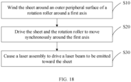
- the sheet processing method is applicable to processing equipment 100 and includes the following steps: S 10: Winding the sheet 200 around an outer peripheral surface of a rotation roller 20 around a first axis L1.
- a conduit 202 is made in the rotation roller 20, it is necessary to make the sheet 200 cover at least a part of the conduit 202.
- the laser beam H can pass through the conduit 202 and be emitted to the sheet 200, thereby forming marks (preset marks) of laser marking or laser cutting on the sheet 200.
- the motion speed of the sheet 200 is controlled in the same way as controlling the rotating linear speed of the rotation roller 20.
- the first driving mechanism 40 and the sheet driving mechanism 50 may drive the rotation roller 20 and the sheet 200 respectively to move, or the second driving mechanism 60 may drive the rotation roller 20 to rotate, so that the rotation roller 20 roll-feeds the sheet 200.
- the sheet 200 drives the rotation roller 20 to rotate, thereby implementing motion synchronism between the sheet 200 and the rotation roller 20.
- the part that is of the sheet 200 and that winds around the outer peripheral surface of the rotation roller 20 move synchronously with the rotation roller 20 around the first axis L1, and therefore, the part that is of the sheet 200 and that winds around the outer peripheral surface of the rotation roller 20 can move synchronously with the laser assembly 30.
- S30 Causing a laser assembly 30 to drive a laser beam H to be emitted toward the sheet 200.
- the laser assembly 30 drives the laser beam H to be emitted toward the sheet 200
- the laser assembly 30 can drive the laser beam H to oscillate around the second axis L2, thereby tuning the emission angle of the laser beam, and making the laser beam H form a preset mark on the sheet 200.
- the laser assembly 30 may drive the laser beam H to move linearly so that the laser beam H forms a preset mark on the sheet 200.
- the laser assembly 30 may, depending on actual requirements, alternately drive the laser beam H to oscillate around the second axis L2 and drive the laser beam H to move linearly, thereby making the laser beam H form a preset mark on the sheet 200.
- the laser assembly 30 needs to drive the laser beam H to be emitted toward the conduit 202, so that the laser beam H passes through conduit 202 and is emitted to the sheet 200.
- the processing equipment 100 just needs to drive the laser beam H to oscillate around the second axis L2, or drive the laser beam H to move linearly, or alternately drive the laser beam H to oscillate and drive the laser beam H to move linearly, so as to implement laser marking or laser cutting, thereby improving the precision and efficiency of laser marking.
- step S10 includes the following step: S 11: Winding, on a cross section perpendicular to the first axis L1, the sheet 200 around at least a half of the outer peripheral surface of the rotation roller 20.
- the foregoing technical solution increases a contact area between the surface of the sheet 200 and the outer peripheral surface of the rotation roller 20, and increases the friction between the sheet 200 and the rotation roller 20, thereby improving motion synchronism between the sheet 200 and the rotation roller 20, and in turn, improving the precision of laser marking or laser cutting.
Landscapes
- Engineering & Computer Science (AREA)
- Physics & Mathematics (AREA)
- Optics & Photonics (AREA)
- Plasma & Fusion (AREA)
- Mechanical Engineering (AREA)
- Chemical & Material Sciences (AREA)
- Manufacturing & Machinery (AREA)
- Chemical Kinetics & Catalysis (AREA)
- Electrochemistry (AREA)
- General Chemical & Material Sciences (AREA)
- Health & Medical Sciences (AREA)
- General Health & Medical Sciences (AREA)
- Toxicology (AREA)
- Laser Beam Processing (AREA)
- Battery Electrode And Active Subsutance (AREA)
Abstract
Description
- This application relates to the technical field of sheet processing, and in particular, to processing equipment, electrode plate processing equipment, battery processing equipment, and a sheet processing method.
- In some circumstances, in a battery manufacturing process, it is usually necessary to perform laser marking on the electrode plate to facilitate subsequent operations such as stacking of electrode plates. However, currently it is difficult to control the position of the mark during laser marking on an electrode plate, thereby leading to a low precision of laser marking.
- One of objectives of some embodiments of this application is to provide processing equipment, electrode plate processing equipment, battery processing equipment, and a sheet processing method to improve precision of the laser marking.
- The technical solutions provided in some embodiments of this application are as follows:
- According to a first aspect, a piece of processing equipment is provided, including:
- a rotation roller, rotatable around a first axis, where an outer peripheral surface of the rotation roller around the first axis is configured to allow winding of a sheet, and the outer peripheral surface of the rotation roller is able to move synchronously with the sheet around the first axis; and
- a laser assembly, disposed on the rotation roller and able to rotate with the rotation roller, where the laser assembly is configured to drive a laser beam to be emitted toward the sheet, and further configured to drive the laser beam to move linearly and/or oscillate around a second axis that intersects the first axis.
- Based on the foregoing technical solution, when the rotation roller rotates around the first axis, the laser assembly can rotate around the first axis synchronously with the rotation roller, so that the laser assembly moves synchronously with the sheet that winds around the outer peripheral surface of the rotation roller. In this way, during laser marking or laser cutting performed by the processing equipment for the sheet, when the laser assembly drives the laser beam to be emitted toward the sheet, the laser assembly drives the laser beam to oscillate around the second axis, or drives the laser beam to move linearly, or alternately drives the laser beam to move linearly and drives the laser beam to oscillate around the second axis, so as to implement laser marking or laser cutting without a need to drive the laser beam to move along with the sheet, thereby improving the synchronism between the oscillation of the laser beam and the motion of the sheet, and in turn, improving the precision and efficiency of laser marking
- In an embodiment, the first axis and the second axis intersect to define a first plane. The laser assembly is able to drive the laser beam to oscillate in the first plane.
- The foregoing technical solution enables the laser beam to oscillate around the second axis in the first plane, thereby forming a linear mark that extends along the width direction on the sheet, that is, implementing transverse marking or transverse die cutting of the sheet.
- In an embodiment, the first axis and the second axis are straight lines that are in different planes. The laser assembly is able to drive the laser beam to oscillate in a second plane. The second plane is a plane defined by the second axis and a third axis. The third axis is a straight line parallel to the first axis and intersecting the second axis.
- The foregoing technical solution enables the laser beam to oscillate around the second axis in the second plane, thereby forming a linear mark that extends along the width direction on the sheet, that is, implementing transverse marking or transverse die-cutting on the sheet.
- In an embodiment, the laser assembly is able to drive the laser beam to oscillate in a third plane. The third plane is a plane passing through the second axis and intersecting the first axis.
- The foregoing technical solution enables the laser beam to oscillate in the third plane to perform longitudinal marking (or longitudinal die-cutting) or angled marking (or angled die-cutting) on the sheet.
- In an embodiment, the laser assembly is disposed inside the rotation roller, and a conduit that allows passage of the laser beam is made in the rotation roller.
- In the foregoing technical solution, the laser assembly is disposed inside the rotation roller. In this way, the laser beam is able to pass through the conduit to perform laser marking or laser cutting on the sheet, thereby achieving a protection effect on the laser assembly.
- In an embodiment, the linear groove is plural in number, and the plurality of linear grooves are spaced out in the rotation roller.
- Based on the foregoing technical solution, during rotation of the rotation roller for one circle, laser marking or laser cutting can be implemented at a plurality of different positions on the sheet, thereby improving the processing efficiency of the sheet and improving the production efficiency of the sheet.
- In an embodiment, the laser assembly is configured to drive the laser beam to be emitted to a plurality of conduits sequentially; or, the laser assembly is plural in number, and the plurality of laser assemblies are configured to drive the laser beam to be emitted to the corresponding conduits.
- Based on the foregoing technical solution, during rotation of the rotation roller for one circle, laser marking or laser cutting can be implemented at a plurality of different positions on the sheet, thereby improving the processing efficiency of the sheet and improving the production efficiency of the sheet.
- In an embodiment, the rotation roller includes a first housing and a second housing. The second housing is detachably connected to the first housing and combines with the first housing to jointly define an accommodation space configured to accommodate the laser assembly. The conduit is made in the first housing and/or the second housing and communicates with the accommodation space.
- Based on the foregoing technical solution, the first housing and the second housing are detachably connected, thereby facilitating the disassembling and assembling operations for the laser assembly in the accommodation space, and improving the convenience of use of the processing equipment.
- In an embodiment, a distribution direction of the first housing and the second housing intersects the first axis.
- The foregoing technical solution makes the processing equipment is more convenient to use.
- In an embodiment, the conduit is a linear groove.
- Based on the foregoing technical solution, linear marks can be made on the sheet.
- In an embodiment, an extension direction of the linear groove is parallel to the first axis.
- The foregoing technical solution enables the laser beam to implement transverse marking on the sheet.
- In an embodiment, the rotation roller is a rotation roller capable of transmitting the laser beam.
- The foregoing technical solution enables the laser beam to directly pass through the rotation roller so as to be emitted to the sheet. This solution is suitable not only for linear marking, but also for marking of complex shapes such as curved marking. In addition, this solution avoids an impact on the marking precision, where the impact is caused by inaccuracy of the laser beam passing through the conduit.
- In an embodiment, the laser assembly includes a fixing bracket disposed in the rotation roller and a galvo scanner disposed on the fixing bracket. The galvo scanner is configured to reflect the laser beam to oscillate the laser beam around the second axis.
- Based on the foregoing technical solution, the galvo scanner is fixed onto the rotation roller by the fixing bracket, thereby making it convenient to fix the laser assembly onto the rotation roller, and in turn, implementing synchronous motion of the laser assembly and the rotation roller.
- In an embodiment, the laser assembly further includes a first optical fiber connected to the galvo scanner. The first optical fiber is threaded through the rotation roller to protrude out of the rotation roller.
- The foregoing technical solution implements lightguide connection between the galvo scanner and an external laser system, and facilitates the galvo scanner to receive the laser beam emitted by the laser system, so as to implement laser marking or laser cutting.
- In an embodiment, a part that is of the first optical fiber and that is threaded through the rotation roller coincides with the first axis.
- Based on the foregoing technical solution, the first optical fiber can be maximally prevented from being entangled, thereby simplifying the connection between the first optical fiber and an external laser system.
- In an embodiment, the processing equipment further includes:
- a rack;
- a first driving mechanism, disposed on the rack and configured to drive the rotation roller to rotate; and
- a sheet driving mechanism, disposed on the rack and configured to drive the sheet to move, where the first driving mechanism and the sheet driving mechanism are configured to make a rotating linear speed of the rotation roller identical to a motion speed of the sheet.
- Based on the foregoing technical solution, both the rotation roller and the sheet can be driven by the corresponding driving mechanism. On the one hand, both the rotation roller and the sheet can be driven stably, thereby implementing a stable motion effect. On the other hand, the first driving mechanism and the sheet driving mechanism are controlled so that the rotation linear speed of the rotation roller is identical to the motion speed of the sheet, thereby maximally improving motion synchronism between the sheet around the outer peripheral surface of the rotation roller and the rotation roller and improving precision of laser marking or laser cutting.
- In an embodiment, the processing equipment further includes a second driving mechanism. The second driving mechanism is configured to drive the rotation roller to rotate. The rotation roller is configured to roll-feed the sheet during rotation.
- Based on the foregoing technical solution, the second driving mechanism drives the rotation roller to rotate around the first axis. During rotation, the rotation roller can roll-feed the sheet during rotation, thereby implementing synchronous motion of the rotation roller and the sheet around the first axis, and in turn, reducing design of the driving mechanism and simplifying the control complexity of the processing equipment.
- In an embodiment, the processing equipment further includes a pressure roller. The pressure roller is able to rotate around an axis parallel to the first axis. A rotation direction of the pressure roller is opposite to a rotation direction of the rotation roller. A motion channel that allows passage of the sheet exists between the rotation roller and the pressure roller.
- The foregoing technical solution improves motion synchronism between the sheet and the rotation roller, so as to improve the precision of laser marking or laser cutting for the sheet.
- In an embodiment, the processing equipment further includes a sheet driving mechanism. The sheet driving mechanism is configured to drive the sheet to move and is configured in such a way that, on a cross section perpendicular to the first axis, the sheet winds around at least a half of the outer peripheral surface of the rotation roller.
- The foregoing technical solution increases a contact area between the sheet and the rotation roller, and increases the friction between the sheet and the rotation roller, thereby improving motion synchronism between the rotation roller and the sheet around the rotation roller, and in turn, improving the precision of laser marking or laser cutting for the sheet.
- In an embodiment, the outer peripheral surface of the rotation roller is set as a surface that moves synchronously with the sheet through friction.
- The foregoing technical solution maximally avoids the problem of slippage of the sheet against the rotation roller, improves motion synchronism between the sheet and the rotation roller around the first axis, and in turn, improves the precision of laser marking or laser cutting.
- According to a second aspect, a piece of electrode plate processing equipment is provided, including the processing equipment.
- The foregoing technical solution enables the electrode plate processing equipment to possess advantages of high precision and high efficiency of laser marking or laser cutting.
- According to a third aspect, a piece of battery processing equipment is provided, including:
- electrode plate processing equipment, configured to perform laser marking on an electrode plate; and
- stacking equipment, configured to stack the electrode plate.
- The foregoing technical solution improves the precision of laser marking for electrode plates, thereby improving the stacking efficiency of electrode plates and the quality of an electrode assembly formed by stacking the electrode plates.
- According to a fourth aspect, a sheet processing method is provided, applicable to a piece of processing equipment, and including the following steps:
- winding a sheet around an outer peripheral surface of a rotation roller around a first axis;
- driving the sheet and the rotation roller to move synchronously around the first axis; and
- causing a laser assembly to drive a laser beam to be emitted toward the sheet.
- Based on the foregoing technical solution, laser marking or laser cutting can be implemented by just driving the laser beam to move linearly and/or to oscillate around the second axis, thereby improving the precision of laser marking and the efficiency of laser marking.
- In an embodiment, the winding a sheet around an outer peripheral surface of a rotation roller around a first axis includes: winding, by the sheet on a cross section perpendicular to the first axis, around at least a half of the outer peripheral surface of the rotation roller.
- The foregoing technical solution increases a contact area between the surface of the sheet and the outer peripheral surface of the rotation roller to increase the friction between the sheet and the rotation roller, thereby improving motion synchronism between the sheet and the rotation roller, and in turn, improving the precision of laser marking or laser cutting.
- To describe the technical solutions in some embodiments of this application more clearly, the following outlines the drawings to be used in some embodiments or exemplary technical description. Evidently, the drawings outlined below are merely some embodiments of this application. A person of ordinary skill in the art may derive other drawings from such drawings without making any creative efforts.
-
FIG. 1 is a schematic diagram of a laser beam that performs dynamic marking in the related art; -
FIG. 2 is a three-dimensional schematic diagram of a fit between processing equipment and a sheet according to some embodiments of this application; -
FIG. 3 is a three-dimensional schematic diagram of a piece of processing equipment according to some embodiments of this application; -
FIG. 4 is a local sectional view of a piece of processing equipment according to some embodiments of this application; -
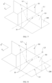
FIG. 5 is a schematic diagram of a laser beam of a piece of processing equipment according to some embodiments of this application; -
FIG. 6 is a schematic diagram of a laser beam of a piece of processing equipment according to some other embodiments of this application; -
FIG. 7 is a schematic diagram of a laser beam of a piece of processing equipment according to some other embodiments of this application; -
FIG. 8 is a schematic diagram of a laser beam of a piece of processing equipment according to some other embodiments of this application; -
FIG. 9 is a schematic diagram of a laser beam of a piece of processing equipment according to some other embodiments of this application; -
FIG. 10 is a schematic diagram of a laser beam of a piece of processing equipment according to some embodiments of this application; -
FIG. 11 is a schematic diagram of a laser beam of a piece of processing equipment according to some other embodiments of this application; -
FIG. 12 is a schematic diagram of control of a piece of processing equipment according to some embodiments of this application; -
FIG. 13 is a sectional view of a fit between a rotation roller and a sheet according to some embodiments of this application; -
FIG. 14 is a schematic diagram of control of a piece of processing equipment according to some other embodiments of this application; -
FIG. 15 is a schematic view of a fit between a rotation roller and a pressure roller according to some embodiments of this application; -
FIG. 16 is a sectional view of a rotation roller according to some embodiments of this application; -
FIG. 17 is a schematic diagram of a piece of battery processing equipment according to some embodiments of this application; and -
FIG. 18 is a flowchart of a sheet processing method according to some embodiments of this application. - 1000-electrode plate processing equipment; 2000-stacking equipment; 100-processing equipment; 200-sheet; 10-rack; 11-rack body; 12-connecting arm; 20-rotation roller; 201-accommodation space; 202-linear groove; 21-first housing; 22-second housing; 30-laser assembly; 31-fixing bracket; 32-galvo scanner; 33-F-Theta field lens; 34-first optical fiber; 35-first plug connector; 36-second plug connector; 37-cable; 40-first driving mechanism; 50-sheet driving mechanism; 60-second driving mechanism; 70-pressure roller; 80-motion channel; A-optical path tuning apparatus; A1-first galvo scanner; A2-second galvo scanner; B-electrode plate; M1-first rotation plane; M2-second rotation plane; L1-first axis; L2-second axis; S1-first plane; S2-second plane; S3-third plane; H-laser beam.
- The following describes some embodiments of this application in detail. Examples of the embodiments are shown in the drawings, throughout which the same or similar reference numerals represent the same or similar components or the components of the same or similar functions. The embodiments described below with reference to the drawings are exemplary, and are intended to construe this application but not to limit this application.
- Understandably, in the description of this application, a direction or positional relationship indicated by the terms such as "length", "width", "up", "down", "front", "back", "left", "right", "vertical", "horizontal", "top", "bottom", "in", and "out" is a direction or positional relationship based on the illustration in the drawings, and is merely intended for ease or brevity of description of this application, but does not necessarily mean or imply that the indicated device or component is located in the specified direction or constructed or operated in the specified direction. Therefore, such terms are not to be understood as a limitation on this application.
- In addition, the technical terms such as "first" and "second" are used merely for ease of description, but not to indicate or imply relative importance or implicitly specify the number of technical features mentioned. Therefore, a feature qualified by "first" or "second" may explicitly or implicitly include one such feature or a plurality of the features.
- In the description of this application, unless otherwise expressly specified, "a plurality of" means at least two, and the term "at least two" includes two. Correspondingly, "a plurality of" means at least two, and includes two.
- In the description of this application, unless otherwise expressly specified and defined, the technical terms such as "mounting", "concatenation", "connection", and "fixing" need to be understood in a broad sense, for example, understood as a fixed connection or a detachable connection or integrally formed; or understood as a mechanical connection or an electrical connection; understood as a direct connection, or an indirect connection implemented through an intermediary; or understood as internal communication between two components or interaction between two components. A person of ordinary skill in the art is able to understand the specific meanings of the terms in this application according to specific situations.
- In the description of this application, the term "and/or" merely indicates a relationship between related items, and represents three possible relationships. For example, "A and/or B" may represent the following three circumstances: A alone, both A and B, and B alone. In addition, the character "/" herein generally indicates an "or" relationship between the item preceding the character and the item following the character.
- A manufacturing process of the battery usually includes a step of winding or stacking a positive electrode plate and a negative electrode plate to form an electrode assembly. In a stacking process of the electrode plates, a film coating on the surface of an electrode plate is removed by laser marking on the electrode plate, so that a mark extending along a width direction of the electrode plate is formed on the surface of the electrode plate. Therefore, the electrode plate can be folded conveniently along the mark, thereby facilitating the stacking process of the electrode plate.
- However, it is difficult to control the position of the mark during the laser marking on the electrode plate, thereby leading to a low precision of laser marking.
- In some circumstances, the electrode plate is generally laser-marked when being conveyed, which is known as dynamic marking. In order to enable a laser beam to form a preset mark on the surface of the electrode plate, the laser beam possesses at least two freely moving orientations. In other words, the laser beam possesses at least two motion dimensions. One of the motion dimensions corresponds to the motion of the electrode plate so that the laser beam can move along with the electrode plate. The other motion dimension corresponds to the mark to be made, so that the laser beam makes a preset mark on the electrode plate.
- In a process of dynamic marking, the laser beam generally moves synchronously with the electrode plate through an encoder. The encoder is prone to problems such as slipping and wear, resulting in abnormality of motion synchronization between the laser beam and the electrode plate. Moreover, the laser beam itself is also prone to problems such as zero drift. In this way, the motion synchronism between the laser beam and the electrode plate is prone to be inferior, thereby reducing the precision of laser marking of the electrode plate.
- To solve the above technical problem, the inventor hereof finds that a buffer assembly may be disposed before and after a marking position of the electrode plate. When the electrode plate needs to be laser-marked, the buffer assembly causes the electrode plate in the marking position to be in a static state. In this way, the laser can perform laser marking when the electrode plate is in a static state, which is known as static marking. However, the buffer assembly for static marking needs to be started and shut down frequently, thereby limiting the overall speed of laser marking of the equipment and leading to low efficiency of laser marking, and in turn, reducing the production efficiency of the electrode plate.
- Based on the above factors, the inventor has designed a piece of processing equipment after in-depth research, that is, the processing equipment mentioned in some embodiments of this application. In the processing equipment, the laser assembly moves synchronously with the electrode plate. Therefore, during laser marking on the electrode plate, there is no need to separately drive the laser beam to keep in sync with the electrode plate in motion. In contrast to the dynamic marking in the related art, this processing equipment improves motion synchronism between the laser beam and the electrode plate, and in turn, improves the precision of laser marking. In addition, in contrast to static marking, this processing equipment does not need to use a buffer assembly, and does not have to be frequently started and shut down, thereby improving the efficiency of laser marking.
- Understandably, the processing equipment according to this application is also applicable to scenarios such as laser cutting or marking in other fields. The uses of the processing equipment are not limited in this application.
- For ease of describing the technical solution of this application, a laser beam and laser marking are briefly described below:
- A laser beam is a beam characterized by an extremely small beam angle, an extremely high degree of collimation (good directionality), and relatively concentrated energy. A laser beam for marking is approximately equivalent to a very narrow beam of high-energy parallel light.
- An optical axis of the laser beam is a central axis of the laser beam in a transmission direction of the beam. If the shape of the laser beam is regarded as a cone, the optical axis of the laser beam may be regarded as a geometric central axis passing through an apex angle of the cone and perpendicular to the bottom face of the cone. An extension direction of the optical axis of the laser beam is basically identical to a projection direction, transmission direction, or extension direction of the laser beam. Therefore, the direction of the laser beam referred to in this embodiment is equivalent to the direction of the optical axis of the laser beam.
- By using the characteristics such as high degree of collimation and high energy of the laser beam, laser marking projects the laser beam onto a surface of a medium, such as the surface of an electrode plate. A light spot struck by the laser beam on the electrode plate acts on the material of the electrode plate to result in a change of the material of the electrode plate. In this way, the laser beams are struck densely according to a preset pattern so as to form a mark of a preset shape.
- Referring to
FIG. 1, FIG. 1 is a schematic diagram of a laser beam H that performs dynamic marking in the related art. During dynamic marking, the laser beam H is projected onto the electrode plate B after being reflected by an optical path tuning apparatus A. For example, the optical path tuning apparatus A is a two-dimensional galvo scanner. The first galvo scanner A1 rotates in a first rotation plane M1, and is configured to reflect a laser beam H incident on a surface of the first galvo scanner. The first rotation plane M1 is parallel to a length direction of the electrode plate B, that is, the motion direction of the electrode plate B. The length direction of the electrode plate B is the direction X shown in the drawing. In this way, the laser beam H can move in the direction X along with the electrode plate B. The second galvo scanner A2 rotates in the second rotation plane M2, and is configured to reflect the laser beam H from the first galvo scanner A1 so that the laser beam H strikes the electrode plate B. The second rotation plane M2 is parallel to the width direction of the electrode plate B. The width direction of the electrode plate B is the direction Y shown in the drawing. In this way, the laser beam H can move along the direction Y of the electrode plate B to implement laser marking. Understandably, the laser beam H may be incident on the second galvo scanner A2 first instead, and then reflected to the first galvo scanner A1 by the second galvo scanner A2, and finally reflected onto the electrode plate B by the first galvo scanner A1, thereby also implementing laser marking. Evidently, the motion of the electrode plate B and the rotation of the first galvo scanner A1 affect the degree of synchronization between the laser beam H and the electrode plate B. If a high degree of synchronization fails to be achieved, the position of the light spot of the laser beam H that strikes the electrode plate B may deviate from a preset position by a distance ahead or behind, thereby impairing the precision of laser marking. - Referring to
FIG. 1 and FIG. 2 , a first aspect of some embodiments of this application provides a piece ofprocessing equipment 100. Theprocessing equipment 100 is primarily configured to perform laser marking on the electrode plate B to form a preset mark on the electrode plate B. Further, depending on actual application requirements, theprocessing equipment 100 may perform laser marking onother sheets 200 different from the electrode plate B, such as a separator. In addition, theprocessing equipment 100 may not only perform laser marking on thesheet 200, but also perform laser cutting on thesheet 200, and specifically, die-cut thesheet 200 to form a preset mark on thesheet 200. - Referring to
FIG. 2 to FIG. 4 , theprocessing equipment 100 primarily includes arotation roller 20 and alaser assembly 30. Therotation roller 20 can rotate around the first axis L1. An outer peripheral surface of therotation roller 20 around the first axis L1 is configured to allow winding of asheet 200. The outer peripheral surface of therotation roller 20 is able to move synchronously with thesheet 200 around the first axis L1. Thelaser assembly 30 is disposed on therotation roller 20 and can rotate around the first axis L1 along with therotation roller 20. Thelaser assembly 30 is configured to drive the laser beam H to be emitted toward thesheet 200 so that the laser beam H performs laser marking or laser cutting on thesheet 200. Thelaser assembly 30 can also drive the laser beam H to move linearly; or, thelaser assembly 30 can also drive the laser beam H to oscillate around the second axis L2; or, thelaser assembly 30 can drive the laser beam H to move linearly on the basis of driving the laser beam H to oscillate around the second axis L2. The first axis L1 and the second axis L2 intersect. - The oscillation of the laser beam H and the linear movement of the laser beam H may be collectively referred to as the motion of the laser beam H.
- When the
sheet 200 is unfolded, thesheet 200 has a length direction and a width direction perpendicular to each other. The length direction of thesheet 200 is parallel to the motion direction of thesheet 200. As shown inFIG. 1 andFIG. 5 toFIG. 9 , the width direction of thesheet 200 is the direction Y shown in the drawings, and the length direction of thesheet 200 is the direction X shown in the drawings. - The
rotation roller 20 is a columnar structure with an outer peripheral surface being a cylindrical surface. The outer peripheral surface of therotation roller 20 is a cylindrical surface so that thesheet 200 can be laid flat on the outer peripheral surface of therotation roller 20 and can wind around the outer peripheral surface of therotation roller 20. The first axis L1 means a central axis of therotation roller 20. The rotation by therotation roller 20 around the first axis L1 means that therotation roller 20 rotates around the first axis L1 as a central axis. The first axis L1 is parallel to an axial direction of therotation roller 20. The first axis L1 is parallel to the width direction of thesheet 200 when thesheet 200 winds around the outer peripheral surface of therotation roller 20 around the first axis L1. - "The outer peripheral surface of the
rotation roller 20 is able to move synchronously with thesheet 200 around the first axis L1" means that a part of thesheet 200, which winds around the outer peripheral surface of therotation roller 20, can move synchronously with therotation roller 20 around the first axis L1, but does not mean that all parts of thesheet 200 being conveyed move synchronously with therotation roller 20 around the first axis L1. Understandably, thesheet 200 can move along the length direction of thesheet 200. In the motion direction of thesheet 200, thesheet 200 can continuously move around therotation roller 20. The part that is of thesheet 200 and that winds aroundrotation roller 20 is wound around the outer peripheral surface of therotation roller 20 around the first axis L1. In this way, the part that is of thesheet 200 and that winds around the outer peripheral surface of therotation roller 20 can move around the first axis L1 along the outer peripheral surface of therotation roller 20. In addition, the motion speed of thesheet 200 is identical to the rotating linear speed of therotation roller 20, so that the part that is of thesheet 200 and that moves around the outer peripheral surface of therotation roller 20 can move synchronously with therotation roller 20 around the first axis L1. - The
laser assembly 30 means an assembly capable of emitting a laser beam H at a preset angle. When thelaser assembly 30 emits the laser beam H to thesheet 200, the emitted laser beam H can perform laser marking or laser cutting on thesheet 200. In some embodiments, thelaser assembly 30 can adjust an emission angle of the laser beam H. To be specific, thelaser assembly 30 can adjust the oscillation direction of the laser beam H so as to adjust the emission angle of the laser beam H and emit the laser beam H at a preset emission angle. Based on this, thelaser assembly 30 can drive the laser beam H to oscillate to adjust the position of the light spot of the laser beam H on thesheet 200, thereby forming a plurality of continuous light spots on thesheet 200 to form marks of laser marking or laser cutting on thesheet 200. In some other embodiments, thelaser assembly 30 can also adjust the emission position of the laser beam H against thesheet 200, so as to emit the laser beam H toward different positions on thesheet 200 at a preset angle. Based on this, thelaser assembly 30 can drive the laser beam H to move linearly to adjust the position of the light spot of the laser beam H on thesheet 200, thereby forming a plurality of continuous light spots on thesheet 200 to form marks of laser marking or laser cutting on thesheet 200. - It is hereby noted that the
laser assembly 30 being able to emit the laser beam H does not mean that thelaser assembly 30 is able to generate laser light. Specifically, thelaser assembly 30 is configured to be connected to an external laser system through lightguide. The external laser system primarily includes a laser generator configured to generate laser light. The laser generator is connected to thelaser assembly 30 through lightguide. In some implementations, the laser generator is disposed outside therotation roller 20. In some other implementations, the laser generator and thelaser assembly 30 are both disposed on therotation roller 20. Disposing the laser generator outside therotation roller 20 can avoid the problem of unstable rotation of therotation roller 20 caused by gravity of the laser generator, thereby improving the rotation stability of therotation roller 20, and in turn, improving stability and precision of laser marking or laser marking. - During operation, the laser generator emits a laser beam H. The laser beam H is transmitted to the
laser assembly 30 through lightguide. Thelaser assembly 30 receives the laser beam H emitted by the laser generator. Moreover, thelaser assembly 30 drives the laser beam H to oscillate around the second axis L2, so as to adjust the emission angle of the laser beam H. In this way, the laser beam H is emitted to thesheet 200 at a preset emission angle, thereby forming marks on thesheet 200. Alternatively, thelaser assembly 30 drives the laser beam H to move linearly, so as to adjust the emission position of the laser beam H against thesheet 200. In this way, the laser beam H is emitted to thesheet 200, thereby forming marks on thesheet 200. Alternatively, thelaser assembly 30 alternately drives the laser beam H to oscillate around the second axis L2 and drives the laser beam H to move linearly, thereby forming a preset mark on thesheet 200. Understandably, on the basis that thelaser assembly 30 is capable of both driving the laser beam H to oscillate around the second axis L2 and driving the laser beam H to move linearly, thelaser assembly 30 may choose whether to drive the laser beam H to oscillate or to drive the laser beam H to move linearly depending on actual application requirements, so as to meet the requirement of making the desired marks. - It is hereby noted that the
laser assembly 30 is disposed on therotation roller 20 and can rotate along with therotation roller 20. To be specific, when thelaser assembly 30 is disposed on therotation roller 20, thelaser assembly 30 and therotation roller 20 are relatively fixed. In this way, when therotation roller 20 rotates around the first axis L1, thelaser assembly 30 can rotate synchronously with therotation roller 20 around the first axis L1. In this way, thelaser assembly 30 can rotate synchronously with therotation roller 20, and in turn, can move synchronously with a part of thesheet 200 around the first axis L1, where the part of the sheet winds around the outer peripheral surface of therotation roller 20. Further, in laser marking or laser cutting on thesheet 200, it is not necessary to separately drive the laser beam H to move along with thesheet 200. As long as thelaser assembly 30 remains fixed to therotation roller 20 tightly, the oscillation of the laser beam H can be highly synchronized with the motion of thesheet 200. - The oscillation of the laser beam H around the second axis L2 means that the laser beam H oscillates left and right around the second axis L2, but the oscillation may be but without limitation a left-right symmetrical oscillation around the second axis L2. The
laser assembly 30 drives the laser beam H to be emitted toward thesheet 200. When the laser beam H is driven to oscillate around the second axis L2, a spot track of the laser beam H striking thesheet 200 is a mark made by the laser beam H on thesheet 200. - The
laser assembly 30 controls the laser beam H to oscillate around the second axis L2, so as to enable the laser beam H to make a preset mark on thesheet 200. As for how the laser beam H oscillates to make what marks on thesheet 200, examples will be given below, and details are omitted here. - The intersection between the second axis L2 and the first axis L1 specifically means that the first axis L1 is not parallel to the second axis L2. In other words, an angle greater than 0° and less than 180° can be formed between the first axis L1 and the second axis L2.
- The laser beam H moves linearly, and therefore, the position of the light spot of the laser beam H on the
sheet 200 also moves linearly, so that the laser beam H can form marks on thesheet 200. The laser beam H may move linearly in a preset direction. In some embodiments, the direction in which the laser beam H moves linearly is parallel to the first axis L1, so that the marks formed by the laser beam H on thesheet 200 are linear marks and parallel to the first axis L1. Definitely, in some other embodiments, the laser beam H can also move linearly along a direction that intersects the first axis L1, so as to form a linear mark on thesheet 200, where the linear mark intersects the first axis L1. In still some other embodiments, the laser beam H can move linearly in different directions sequentially, so as to form fold line marks on thesheet 200. As regards what marks can be formed on thesheet 200 by the linear movement of the laser beam H, the marks can be designed depending on actual application requirements, without being enumerated exhaustively herein. - The
processing equipment 100 according to some embodiments of this application achieves the following effects: - First, when the
rotation roller 20 rotates around the first axis L1, thelaser assembly 30 rotates synchronously with therotation roller 20 around the first axis L1, so that the laser beam H can move synchronously with thesheet 200. A light spot of the laser beam H acting on thesheet 200 is basically prevented from deviating from a preset position, thereby implementing the effect of "static marking" during the motion of thesheet 200. At the same time, the laser beam H oscillates around the second axis L2 at a preset angle and in a preset direction, or the laser beam H moves linearly in a preset direction, so that the laser beam H can form a preset mark on thesheet 200 while moving along with thesheet 200. In this way, theprocessing equipment 100 just needs to drive the laser beam H to oscillate around the second axis L2, or drive the laser beam H to move linearly, or alternately drive the laser beam H to oscillate and drive the laser beam H to move linearly, so as to implement laser marking or laser cutting without a need to drive the laser beam H to move along with thesheet 200, thereby improving the motion synchronism between the laser beam H and thesheet 200, and in turn, improving the precision and efficiency of laser marking. - Second, the buffer assembly in the relevant static marking technology is omitted, thereby avoiding the problems of slow speed and low efficiency of laser marking of the
sheet 200 caused by frequent start and shutdown of the buffer assembly. - In addition, the problem of zero drift of the laser beam caused by the complex motion of the laser beam H is alleviated, thereby improving the precision of laser marking.
- Moreover, the omission of the buffer assembly in the relevant static marking technology brings the following effects: on the one hand, the omission of the buffer assembly avoids the problems of a complex structure and a large size of the
processing equipment 100 caused by the buffer assembly and the driving mechanism configured to drive the buffer assembly to move. On the other hand, the omission of the buffer assembly avoids the problem of wear and tear of theprocessing equipment 100 caused by the frequent start and shutdown of the buffer assembly. Third, the omission of the buffer assembly avoids the problem of violent fluctuations of the tension of thesheet 200 caused by the frequent start and shutdown of the buffer assembly, thereby improving the precision of laser marking of thesheet 200. - The first axis L1 and the second axis L2 may be located in the same plane or in different planes.
- In some embodiments, referring to
FIG. 4 andFIG. 5, FIG. 5 is a schematic diagram of a laser beam H according to some embodiments of this application. When the first axis L1 and the second axis L2 are located in the same plane, the first axis L1 intersects the second axis L2 to define afirst plane S 1. Thelaser assembly 30 is able to drive the laser beam H to oscillate in thefirst plane S 1. - Understandably, the first plane S1 is a plane defined by the first axis L1 and the second axis L2.
- In this case, the oscillation of the laser beam H around the second axis L2 may mean that the laser beam H oscillates left and right around the second axis L2 in the first plane S1, but the oscillation is not limited to a left-right symmetrical oscillation.
- In some other embodiments, referring to
FIG. 4 andFIG. 6, FIG. 6 is a schematic diagram of a laser beam H according to some other embodiments of this application. When the first axis L1 and the second axis L2 are located in different planes, that is, when the first axis L1 and the second axis L2 are straight lines in different planes, a third axis L3 parallel to the first axis L1 may be made, and the third axis L3 intersects the second axis L2 to define a second plane S2. Thelaser assembly 30 is able to drive the laser beam H to oscillate in the second plane S2. Understandably, the second plane S2 is a plane defined by the second axis L2 and a third axis L3. The third axis L3 is a straight line parallel to the first axis L1 and intersecting the second axis L2. - In this case, the oscillation of the laser beam H around the second axis L2 may mean that the laser beam H oscillates left and right around the second axis L2 in the second plane S2, but the oscillation is not limited to a left-right symmetrical oscillation.
- As shown in
FIG. 4 to FIG. 6 , when thelaser assembly 30 drives the laser beam H to be emitted toward thesheet 200, thelaser assembly 30 drives the laser beam H to oscillate around the second axis L2 in the first plane S1 or the second plane S2. Because the first axis L1 falls in the first plane S1 and the first axis L1 is parallel to the second plane S2, both the first plane S1 and the second plane S2 are parallel to the width direction of thesheet 200. Moreover, the second axis L2 is located in the first plane S1 or the second plane S2. Therefore, the laser beam H oscillates around the second axis L2 in the first plane S1 or the second plane S2, and the track of the light spot on thesheet 200 is always a linear mark. The linear mark is parallel to the first axis L1, that is, parallel to the width direction of thesheet 200, and is suitable for transverse marking or transverse die-cutting of thesheet 200. - The oscillation of the laser beam H around the second axis L2 in the first plane S1 or the second plane S2 may be left-right symmetrical with respect to the second axis L2 or may be left-right asymmetrical, without affecting the spot track, that is, without affecting the shape of the mark. Definitely, when the laser beam H oscillates around the second axis L2 in the first plane S1 or the second plane S2 by oscillating symmetrically left and right around the second axis L2, it is convenient to control the projection direction of the laser beam H.
- The foregoing technical solution enables the laser beam H to oscillate around the second axis L2 in the first plane S1 or the second plane S2, thereby forming a linear mark that extends along the width direction on the
sheet 200, that is, implementing transverse marking or transverse die-cutting on thesheet 200. - In some embodiments, referring to
FIG. 4 andFIG. 7 toFIG. 9 , thelaser assembly 30 is able to drive the laser beam H to oscillate in a third plane S3. The third plane S3 is a plane passing through the second axis L2 and intersecting the first axis L1. - When the
laser assembly 30 drives the laser beam H to be emitted toward thesheet 200, the laser beam H may tilt at an angle to the first plane S1 or the second plane S2 and oscillate around the second axis L2 without oscillating around the second axis L2 in the first plane S1 or the second plane S2. In other words, the laser beam H oscillates around the second axis L2 and is emitted at an angle to the first plane S1 or the second plane S2. In this case, the laser beam H and the second axis L2 define the third plane S3. The third plane S3 defined by the laser beam H and the second axis L2 is neither parallel to the first plane S1 nor parallel to the first axis L1, and the third plane S3 intersects the first axis L1. The laser beam H oscillates around the second axis L2 in the third plane S3. In this case, the oscillation of the laser beam H around the second axis L2 may mean that the laser beam H oscillates left and right around the second axis L2 in the third plane S3, but the oscillation is not limited to a left-right symmetrical oscillation. Therefore, the laser beam H oscillates around the second axis L2 in the third plane S3, and the track of the light spot on thesheet 200 is not parallel to the first axis L1, that is, not parallel to the width direction of thesheet 200. Correspondingly, the mark formed by the laser beam H on thesheet 200 is neither parallel to the first axis L1 nor parallel to the width direction of thesheet 200. - As an example, as shown in
FIG. 7 and FIG. 8 , when the third plane S3 is parallel to the length direction or the motion direction of thesheet 200, the laser beam H can form, on thesheet 200, a mark parallel to the length direction of thesheet 200, and may be configured to perform longitudinal marking or longitudinal die-cutting of electrode plates. As shown inFIG. 7 , the first axis L1 intersects the second axis L2, the first axis L1 intersects the third plane S3, the second axis L2 falls into the third plane S3, and the third plane S3 is parallel to the length direction of thesheet 200, that is, the direction X shown in the drawing. In this case, the laser beam H can form, on thesheet 200, a mark parallel to the length direction of thesheet 200. As shown inFIG. 8 , the first axis L1 and the second axis L2 are straight lines in different planes. Both the first axis L1 and the third axis L3 intersect the third plane S3. The second axis L2 falls into the third plane S3, and the third plane S3 is parallel to the width direction of thesheet 200, that is, the direction Y shown in the drawing. In this case, the laser beam H can form, on thesheet 200, a mark parallel to the width direction of thesheet 200. - As an example, as shown in
FIG. 9 , when the third plane S3 is neither parallel to the length direction of thesheet 200 nor parallel to the width direction of thesheet 200, the laser beam H can form an angled mark on thesheet 200, thereby implementing angled marking or angled die-cutting. To be specific, as shown inFIG. 9 , the first axis L1 intersects the second axis L2, the third plane S3 intersects the first axis L1, the second axis L2 falls into the third plane S3, and the third plane S3 intersects the length direction of thesheet 200 and the width direction of thesheet 200 separately. In this case, the laser beam H can form an angled mark on thesheet 200. In addition, when the first axis L1 and the second axis L2 are straight lines in different planes, the laser beam H can also form an angled mark on thesheet 200.
The foregoing technical solution enables the laser beam H to oscillate in the third plane S3 to perform longitudinal marking (or longitudinal die-cutting) or angled marking (or angled die-cutting) on thesheet 200. - The word "transverse" in transverse marking or transverse die-cutting means a direction parallel to the width direction of the
sheet 200. The word "longitudinal" in longitudinal marking or longitudinal die-cutting means a direction parallel to the length direction of thesheet 200 in an unfolded state. The word "angled" in angled marking or angled die-cutting means a direction that tilts at an angle to both the longitudinal direction and the transverse direction. - In addition, based on the above structure, the
laser assembly 30 may further control the laser beam H to oscillate around the second axis L2 in at least two dimensions, that is, oscillate in different planes (for example, the first plane S1, the second plane S2, and the third plane S3) over time, so as to implement fold line marking, curve marking, and the like. For example, thelaser assembly 30 may drive the laser beam H to sequentially oscillate in three different third planes S3, so that the laser beam H forms a triangular mark on thesheet 200. Definitely, the specific shape of the mark may be set according to actual needs, and is not enumerated exhaustively herein. Although this marking method is more complex than driving the laser beam H in linear marking, this marking method eliminates the motion dimension of thesheet 200 in the motion direction. Compared with the dynamic marking in the related art, this marking method can still improve the precision and efficiency of laser marking. - Understandably, when the
laser assembly 30 drives the laser beam H to oscillate around the second axis L2 in the same plane (for example, thefirst plane S 1, the second plane S2, or the third plane S3), the laser beam H always forms a linear mark on thesheet 200. When thelaser assembly 30 drives the laser beam H to oscillate in different planes, the laser beam H can form a fold line mark, a curve mark, or the like on thesheet 200. - To sum up, by controlling the laser beam H to oscillate around the second axis L2, the
laser assembly 30 can implement various forms of marking such as horizontal marking, angled marking, longitudinal marking, fold line marking, and curve marking. - In some embodiments, as shown in
FIG. 10 , the second axis L2 is perpendicular to the first axis L1. In this way, it is convenient to make the laser beam H oscillate symmetrically left and right around the second axis L2. Optionally, the angles of both leftward and rightward oscillations of the laser beam H around the second axis L2 may be set to 90°, 80°, 75°, or another appropriate value. - Definitely, in some other embodiments, as shown in
FIG. 11 , the second axis L2 may be not perpendicular to the first axis L1. In this case, the angle of leftward oscillation of the laser beam H around the second axis L2 may be different from the angle of rightward oscillation. For example, the angle of oscillation of the laser beam H toward one of the left or right side is 120°, and the angle of oscillation toward the other side is 60°. Alternatively, the angle of oscillation of the laser beam H toward one of the left or right side is 100°, and the angle of oscillation toward the other side is 75°, or the like, without being strictly limited herein. - Optionally, in some embodiments, the
laser assembly 30 may be capable of moving linearly on therotation roller 20 to implement linear movement of the laser beam H, so that the emission position of the laser beam H against thesheet 200 is tunable. Specifically, during operation, thelaser assembly 30 may move linearly against therotation roller 20 so as to move linearly against thesheet 200, and in turn, form a linear mark on thesheet 200. - Optionally, a slide rail may be disposed on the
rotation roller 20. Thelaser assembly 30 is slidably disposed on the slide rail. In this way, thelaser assembly 30 can move linearly against therotation roller 20 to implement linear movement of the laser beam H. Moreover, the design of the slide rail needs relative fixing between the slide rail and thelaser assembly 30, so that thelaser assembly 30 can rotate synchronously with therotation roller 20 when therotation roller 20 rotates around the first axis L1. - Based on the foregoing technical solution, the
laser assembly 30 can move linearly against therotation roller 20 to implement the linear movement effect of the laser beam H. - In some embodiments, referring to
FIG. 2 to FIG. 4 , thelaser assembly 30 is disposed inside therotation roller 20. Aconduit 202 is made in therotation roller 20. Theconduit 202 is configured to allow passage of the laser beam H. - As shown in
FIG. 3 and FIG. 4 , anaccommodation space 201 is made inside therotation roller 20. Theaccommodation space 201 is configured to accommodate thelaser assembly 30. Theconduit 202 communicates with theaccommodation space 201 inside therotation roller 20 and is exposed outside therotation roller 20. In addition, when thesheet 200 winds around the outer peripheral surface of therotation roller 20 around the first axis L1, theconduit 202 directly faces thesheet 200. An emergent side of thelaser assembly 30 is disposed toward theconduit 202. - When the
processing equipment 100 is in operation, thesheet 200 winds around therotation roller 20 and covers at least a part of theconduit 202. In this way, thelaser assembly 30 can drive the laser beam H to be emitted toward theconduit 202. The laser beam H passes through theconduit 202, and performs laser marking or laser cutting on thesheet 200 that covers theconduit 202. - The shape of the
conduit 202 may be designed according to the shape of the preset mark, and specifically, may be the shape of a straight line, a curve, or a fold line. As shown inFIG. 3 and FIG. 4 , theconduit 202 is a linear groove. Definitely, in some other embodiments, the shape may be designed according to the shape of the preset mark, without being limited herein. - In the foregoing technical solution, the
laser assembly 30 is disposed inside therotation roller 20. In this way, the laser beam H is able to pass through theconduit 202 to perform laser marking or laser cutting on thesheet 200, thereby achieving a protection effect on thelaser assembly 30. - Optionally, as shown in
FIG. 3 and FIG. 4 , thelaser assembly 30 may be disposed on an inner peripheral side of therotation roller 20. In this way, the emergent side of thelaser assembly 30 can face theconduit 202 more accurately, so that the laser beam H can be emitted onto thesheet 200 toward theconduit 202. Definitely, in some other embodiments, thelaser assembly 30 may be disposed at an upward axial end of therotation roller 20. - In some embodiments, referring to
FIG. 2 to FIG. 4 , there is oneconduit 202. - When the
processing equipment 100 is in operation, thesheet 200 winds around the outer peripheral surface of therotation roller 20 and covers a part of theconduit 202. During rotation of therotation roller 20 for one circle, thelaser assembly 30 keeps driving the laser beam H to pass through theconduit 202 to perform laser marking or laser cutting on the same position on thesheet 200. When therotation roller 20 proceeds to rotate for a next circle, thelaser assembly 30 drives the laser beam H to pass through theconduit 202 to perform laser marking or laser cutting on a next position on thesheet 200. - Based on the foregoing technical solution, during rotation of the
rotation roller 20 for one circle, thelaser assembly 30 drives the laser beam H to perform laser marking or laser cutting on the same position on thesheet 200. With such an arrangement, on a condition that the position for laser marking or laser cutting on thesheet 200 is predetermined, the diameter of therotation roller 20 can be reduced to downsize theprocessing equipment 100. Correspondingly, on a condition that the diameter of therotation roller 20 is predetermined, the time for the laser beam H to perform laser marking or laser cutting for each position on thesheet 200 can be extended, thereby improving quality of the marks formed on thesheet 200. - In some embodiments, the
conduit 202 may be plural in number, and the plurality ofconduits 202 are spaced out in therotation roller 20. - The plurality of
conduits 202 may be spaced out along any direction. As an example, the extension direction of theconduits 202 is parallel to the first axis L1, and the plurality ofconduits 202 are sequentially distributed on therotation roller 20 around thefirst axis L 1 circumferentially. - Based on the foregoing technical solution, when the
processing equipment 100 is in operation, thesheet 200 winds around the outer peripheral surface of therotation roller 20 and covers the plurality ofconduits 202. During rotation of therotation roller 20 for one circle, the laser beam H is emitted to one of theconduits 202 first, so that the laser beam H performs laser marking or laser cutting on the corresponding position on thesheet 200 through theconduit 202. Subsequently, the laser beam H is emitted toward anext conduit 202, so that the laser beam H performs laser marking or laser cutting on a next corresponding position on thesheet 200 through theconduit 202, and so on. With such an arrangement, a plurality ofconduits 202 spaced apart are made in therotation roller 20. Therefore, during rotation of therotation roller 20 for one circle, laser marking or laser cutting can be implemented at a plurality of different positions on thesheet 200, thereby improving the processing efficiency of thesheet 200 and improving the production efficiency of thesheet 200. - In some embodiments, the
laser assembly 30 is configured to sequentially drive the laser beam H to be emitted toward a plurality ofconduits 202. - The
laser assembly 30 can drive the laser beam to oscillate, so that thelaser assembly 30 emits the laser beam toward any one of the plurality ofconduits 202. - When the
processing equipment 100 is in operation, thesheet 200 winds around the outer peripheral surface of therotation roller 20 and covers the plurality ofconduits 202. During rotation of therotation roller 20 for one circle, thelaser assembly 30 drives the laser beam H to be emitted toward one of theconduits 202 first, so that the laser beam H performs laser marking or laser cutting on the corresponding position on thesheet 200 through theconduit 202. Subsequently, thelaser assembly 30 drives the laser beam H to oscillate around the second axis L2, so that the laser beam H is emitted toward anext conduit 202, and so that the laser beam H performs laser marking or laser cutting on a next corresponding position on thesheet 200 through theconduit 202, and so on. During rotation of therotation roller 20 for one circle, thelaser assembly 30 can drive the laser beam H to sequentially perform laser marking or laser cutting on a plurality of different positions on thesheet 200. - Alternatively, in some other embodiments, the
laser assembly 30 is plural in number. The plurality oflaser assemblies 30 are configured to drive the laser beam H to be emitted to the correspondingconduits 202. - The emergent sides of the plurality of
laser assemblies 30 are oriented toward a plurality ofconduits 202 in one-to-one correspondence. - When the
processing equipment 100 is in operation, thesheet 200 winds around the outer peripheral surface of therotation roller 20 and covers the plurality ofconduits 202. During rotation of therotation roller 20 for one circle, eachlaser assembly 30 emits the laser beam H toward acorresponding conduit 202, so as to perform laser marking or laser cutting on the corresponding position on thesheet 200. In other words, the laser beams H emitted by the plurality oflaser assemblies 30 can pass through the correspondingconduits 202. In this way, during rotation of therotation roller 20 for one circle, the laser beams can implement the laser marking or laser cutting on a plurality of different positions on thesheet 200 respectively. - Based on the foregoing technical solution, the
laser assembly 30 can drive the laser beam H to pass through the plurality ofconduits 202 sequentially, so as to sequentially perform laser marking or laser cutting on a plurality of different positions on thesheet 200. Alternatively, a plurality oflaser assemblies 30 can drive the laser beam H to pass through thecorresponding conduit 202, so as to perform laser marking or laser cutting at a plurality of different positions on thesheet 200 simultaneously. In this way, the processing efficiency of thesheet 200 is improved, and in turn, the production efficiency of thesheet 200 is improved. - In some embodiments, referring to
FIG. 4 andFIG. 16 , therotation roller 20 includes afirst housing 21 and asecond housing 22. Thesecond housing 22 is detachably connected to thefirst housing 21, and combines with thefirst housing 21 to jointly define anaccommodation space 201. Theaccommodation space 201 is configured to accommodate thelaser assembly 30. Theconduit 202 is made in thefirst housing 21, or theconduit 202 is made in thesecond housing 22, or theconduit 202 is made in thefirst housing 21 and thesecond housing 22. Alternatively, theconduit 202 is made in both thefirst housing 21 and thesecond housing 22. In addition, theconduit 202 communicates with theaccommodation space 201. - The
rotation roller 20 may be of diverse structures. For example, thefirst housing 21 is a hollow structure with an opening on one side. Thesecond housing 22 covers the opening side of thefirst housing 21, and combines with thefirst housing 21 to define theaccommodation space 201. For another example, both thefirst housing 21 and thesecond housing 22 are a hollow structure with an opening on one side. The opening side of thesecond housing 22 covers the opening side of thefirst housing 21, and combines with thefirst housing 21 to define theaccommodation space 201. - Based on the foregoing technical solution, the
first housing 21 and thesecond housing 22 are detachably connected, thereby facilitating the disassembling and assembling operations for thelaser assembly 30 in theaccommodation space 201, and improving the convenience of use of theprocessing equipment 100. - Optionally, as shown in
FIG. 4 andFIG. 16 , theprocessing equipment 100 may further include a rack 10 configured to connect therotation roller 20. Thefirst housing 21 is rotatably connected to the rack 10; or thesecond housing 22 is rotatably connected to the rack 10; or, both thefirst housing 21 and thesecond housing 22 are rotatably connected to the rack 10. - In some embodiments, referring to
FIG. 4 andFIG. 16 , a distribution direction of thefirst housing 21 and thesecond housing 22 intersects the first axis L1. - The
first housing 21 and thesecond housing 22 may be sequentially distributed along a radial direction of therotation roller 20. In other words, the distribution direction of thefirst housing 21 and thesecond housing 22 is perpendicular to the first axis L1. For example, as shown inFIG. 16 , both thefirst housing 21 and thesecond housing 22 are a structure with a semicircular cross section, where the cross section means a cross section perpendicular to the first axis L1. The first axis L1 is located between thefirst housing 21 and thesecond housing 22. Definitely, thefirst housing 21 and thesecond housing 22 may be distributed along a direction that intersects the radial direction of therotation roller 20. In other words, the distribution direction of thefirst housing 21 and thesecond housing 22 is neither parallel nor perpendicular to the first axis L1. - Based on the foregoing technical scheme, when an axial end of the
rotation roller 20 is rotatably connected to the rack 10, thelaser assembly 30 can be disassembled without detaching theentire rotation roller 20 from the rack 10, thereby facilitating the use of theprocessing equipment 100. - In addition, in other embodiments, the
first housing 21 and thesecond housing 22 may be sequentially distributed along an axial direction of therotation roller 20 instead. For example, thefirst housing 21 is a cylindrical structure, and an opening is made at an axial end of thefirst housing 21. Thesecond housing 22 covers the opening side of thefirst housing 21, so as to combine with thefirst housing 21 to define theaccommodation space 201. - In some embodiments, as shown in
FIG. 2 to FIG. 4 , theconduit 202 is a linear groove. - Based on the foregoing structure, when the
laser assembly 30 drives the laser beam H to move linearly, the movement direction of the laser beam H is parallel to the extension direction of the linear groove. - Based on the foregoing technical solution, the
laser assembly 30 drives the laser beam H to be emitted toward theconduit 202. In this way, after the laser beam H is emitted to thesheet 200, the mark formed on thesheet 200 corresponds to the shape of theconduit 202, and is a linear mark. Therefore, by setting theconduit 202 as a linear groove, a linear mark can be made on thesheet 200. - In some embodiments, as shown in
FIG. 2 to FIG. 4 , the extension direction of theconduit 202 is parallel to the first axis L1. - When the
sheet 200 winds around the outer peripheral surface of therotation roller 20 around the first axis L1 and covers theconduit 202, thelaser assembly 30 drives the laser beam H to pass through theconduit 202 so that the laser beam is emitted to thesheet 200. The laser beam H can form a linear mark on thesheet 200. The linear mark is parallel to the first axis L1 and parallel to the width direction of thesheet 200, such as the direction Y shown inFIG. 2 to FIG. 4 . - Based on the foregoing structure, when the
laser assembly 30 drives the laser beam H to move linearly, the movement direction of the laser beam H is parallel to the first axis L1. - The foregoing technical solution enables the laser beam H to implement transverse marking on the
sheet 200. - Optionally, the length of the
conduit 202 along the direction Y is greater than the dimension of thesheet 200 along the direction Y In this way, when thesheet 200 winds around the outer peripheral surface of therotation roller 20, theconduit 202 protrudes beyond the two ends of thesheet 200 along the direction Y Such an arrangement enables the laser beam to form a complete linear mark on the surface of thesheet 200. - In some other embodiments, the
conduit 202 may also extend along the length direction of thesheet 200, so as to implement the longitudinal marking mentioned above. - In some other embodiments, the
conduit 202 may extend along a direction that is neither parallel to the length direction of thesheet 200 nor parallel to the width direction of thesheet 200, so as to implement the angled marking mentioned above. - In some other embodiments, the
conduit 202 may be absent in therotation roller 20, but therotation roller 20 is arotation roller 20 capable of transmitting the laser beam H. - The
rotation roller 20 is made of a material penetrable by the laser beam, such as but without limitation, a rotatingroller 20 made of a transparent material. - Such an arrangement enables the laser beam H to directly pass through the
rotation roller 20 so as to be emitted to thesheet 200. This solution is suitable not only for linear marking, but also for marking of complex shapes such as curved marking. In addition, this solution avoids an impact on the marking precision, where the impact is caused by inaccuracy of the laser beam H passing through theconduit 202. - In some embodiments, referring to
FIG. 4 , thelaser assembly 30 includes a fixing bracket 31 and agalvo scanner 32. Both the fixing bracket 31 and thegalvo scanner 32 are accommodated inside theaccommodation space 201 inside therotation roller 20. The fixing bracket 31 is disposed inside therotation roller 20, and thegalvo scanner 32 is disposed on the fixing bracket 31. Thegalvo scanner 32 is configured to reflect the laser beam H to oscillate the laser beam H around the second axis L2. - The
galvo scanner 32 is configured to be connected to an external laser system through lightguide. During operation, the external laser system emits a laser beam H, and thegalvo scanner 32 receives the laser beam H and reflects the laser beam H to adjust the emission angle of the laser beam H. In this way, the laser beam H is directed toward theconduit 202 at a preset emission angle under the reflection action of thegalvo scanner 32, so as to be emitted to thesheet 200 to perform laser marking or laser cutting on thesheet 200. - The
galvo scanner 32 is a component capable of reflecting the laser beam H. By reflecting the laser beam H, thegalvo scanner 32 can adjust the emission angle of the laser beam H, so as to drive the laser beam H to be emitted at a preset angle. Thegalvo scanner 32 may be a two-dimensional galvo scanner or a three-dimensional galvo scanner. When thegalvo scanner 32 is a two-dimensional galvo scanner, the working principles of the galvo scanner may be learned by reference to the working principles of the first galvo scanner A1 and the second galvo scanner A2 shown inFIG. 1 . For example, for asimple galvo scanner 32, a plurality of reflecting mirrors exist inside thegalvo scanner 32. The emission angle of the laser beam can be adjusted by adjusting the angles of the plurality of reflecting mirrors, that is, by adjusting the reflecting surfaces of the reflecting mirrors. In this way, by controlling thegalvo scanner 32, thegalvo scanner 32 is caused to drive the laser beam H to oscillate around the second axis L2, so that the laser beam H forms a mark on thesheet 200. - When the fixing bracket 31 is disposed inside the
rotation roller 20 and thegalvo scanner 32 is disposed on the fixing bracket 31, both the fixing bracket 31 and thegalvo scanner 32 may be fixed against therotation roller 20. In this way, both the fixing bracket 31 and thegalvo scanner 32 are relatively fixed to therotation roller 20. When therotation roller 20 rotates around the first axis L1, both the fixing bracket 31 and thegalvo scanner 32 can rotate synchronously with therotation roller 20 around the first axis L1. - Based on the foregoing technical solution, the
galvo scanner 32 is fixed onto therotation roller 20 by the fixing bracket 31, thereby making it convenient to fix thelaser assembly 30 onto therotation roller 20, and in turn, implementing synchronous motion of thelaser assembly 30 and therotation roller 20. - In some embodiments, referring to
FIG. 4 , thelaser assembly 30 further includes a F-Theta field lens 33. The F-Theta field lens 33 is disposed on an emergent side of thegalvo scanner 32 and is configured to focus the laser beam H. - When the F-
Theta field lens 33 is disposed on the emergent side of thegalvo scanner 32, thefield lens 33 and thegalvo scanner 32 are relatively fixed. - The F-
Theta field lens 33 is a component capable of focusing light. Further, the F-Theta field lens 33 is disposed toward theconduit 202. In this way, when thegalvo scanner 32 drives the laser beam H to be emitted toward the F-Theta field lens 33, the laser beam H can be emitted toward theconduit 202 under the focusing effect of the F-Theta field lens 33, so as to be emitted to thesheet 200. - Based on the foregoing technical solution, the F-
Theta field lens 33 can focus the laser beam H, thereby improving the quality of the mark made by the laser beam H through laser marking or laser cutting on thesheet 200. - In some embodiments, referring to
FIG. 2 to FIG. 4 , thelaser assembly 30 further includes a first optical fiber 34. The first optical fiber 34 is configured to implement lightguide connection between thegalvo scanner 32 and an external laser system. The first optical fiber 34 is connected to thegalvo scanner 32. The first optical fiber 34 is threaded through therotation roller 20 to protrude out of therotation roller 20. - The first optical fiber 34 is connected to the
galvo scanner 32 and the external laser system. In this way, when the external laser system emits the laser beam H, the laser beam H can enter thegalvo scanner 32 through the first optical fiber 34, with the emission angle changed by thegalvo scanner 32, and then pass through theconduits 202 sequentially, so as to be emitted to thesheet 200 to perform laser marking or laser cutting on thesheet 200. - One end of the first optical fiber 34 is connected to the
galvo scanner 32. The first optical fiber 34 is threaded through therotation roller 20 to protrude out of therotation roller 20 from theaccommodation space 201 of therotation roller 20. In this way, opposite to the other end of thegalvo scanner 32, the first optical fiber 34 is connected to the external laser system. - The first optical fiber 34 may be threaded out of the
rotation roller 20 from an axial end of therotation roller 20, or may be threaded out of therotation roller 20 from a sidewall of therotation roller 20. It is hereby noted that the position configured to thread out the first optical fiber 34 on therotation roller 20 is generally not configured to allow winding of thesheet 200, so as to prevent the first optical fiber 34 from interfering with the motion of thesheet 200 or from causing damage to the surface of thesheet 200. - Based on the foregoing technical solution, through arrangement of the first optical fiber 34, lightguide connection is implemented between the
galvo scanner 32 and the external laser system, thereby facilitating thegalvo scanner 32 to receive the laser beam H emitted by the laser system, so as to implement laser marking or laser cutting. In addition, compared with the solution in which a laser generator is disposed on therotation roller 20, the foregoing technical solution enables therotation roller 20 to be more stable during rotation, thereby improving the precision of laser marking or laser cutting for thesheet 200. - In some embodiments, referring to
FIG. 2 to FIG. 4 , a part that is of the first optical fiber 34 and that is threaded through therotation roller 20 coincides with the first axis L1. - The part that is of the first optical fiber 34 and that is located between the
galvo scanner 32 and the external laser system is threaded through therotation roller 20. Specifically, as shown inFIG. 2 to FIG. 4 , the first optical fiber 34 is threaded out of therotation roller 20 from the axial end of therotation roller 20. In addition, the part that is of the first optical fiber 34 and that is threaded through therotation roller 20 coincides with the first axis L1. - Based on the foregoing technical solution, the part that is of the first optical fiber 34 and that is threaded through the
rotation roller 20 coincides with the first axis L1. In this way, a central axis of the part that is of the first optical fiber 34 and that is threaded through therotation roller 20 coincides with the first axis L1. When thegalvo scanner 32 rotates around the first axis L1 along with therotation roller 20, the first optical fiber 34 also rotates around the first axis L1 along with thegalvo scanner 32. That is, the first optical fiber 34 rotates around its own central axis. In this way, the entire first optical fiber 34 can be prevented from oscillating around the first axis L1, thereby maximally preventing the first optical fiber 34 from being entangled, and in turn, simplifying the connection between the first optical fiber 34 and the external laser system, that is, simplifying the lightguide connection between thelaser assembly 30 and the external laser system. - Optionally, as shown in
FIG. 4 , thelaser assembly 30 further includes afirst plug connector 35 and a second plug connector 36. Thefirst plug connector 35 is connected to thegalvo scanner 32, and the second plug connector 36 is connected to the first optical fiber 34. Thefirst plug connector 35 and the second plug connector 36 are plug-fitted to implement connection between the first optical fiber 34 and thegalvo scanner 32. The arrangement of thefirst plug connector 35 and the second plug connector 36 simplifies the operation of connecting the first optical fiber 34 and thegalvo scanner 32, thereby improving the convenience of use of theprocessing equipment 100. - Definitely, in other embodiments, the laser generator of the laser system may be disposed in the
rotation roller 20, so that the laser generator can be connected to an external electrical device by a signal cable. In this case, the first optical fiber 34 may be not threaded out of therotation roller 20, but the signal cable is threaded out of therotation roller 20 from inside therotation roller 20. In addition, the part that is of the signal cable and that is threaded through therotation roller 20 may also coincide with the first axis L1, thereby also facilitating rotation of therotation roller 20 and maximally avoiding entanglement of the signal cable. - In some embodiments, referring to
FIG. 4 , thelaser assembly 30 further includes acable 37. Thecable 37 is connected to thegalvo scanner 32. Thecable 37 is threaded through therotation roller 20 to protrude out of therotation roller 20. - The
cable 37 is configured to connect thegalvo scanner 32 and an external control system. The external control system can control the motion of components such as a reflecting mirror in thegalvo scanner 32, so that thegalvo scanner 32 can adjust the emission angle of the laser. - One end of the
cable 37 is connected to thegalvo scanner 32. Thecable 37 is threaded through therotation roller 20 to protrude out of therotation roller 20 from theaccommodation space 201 of therotation roller 20. In this way, opposite to the other end of thegalvo scanner 32, thecable 37 is connected to the external control system, thereby implementing electrical connection between thegalvo scanner 32 and the external control system. - In some embodiments, referring to
FIG. 4 , a part that is of thecable 37 and that is threaded through therotation roller 20 coincides with the first axis L1. Specifically, the part that is of thecable 37 and that is located between thegalvo scanner 32 and the external control system is threaded through therotation roller 20. In addition, the part that is of thecable 37 and that is threaded through therotation roller 20 coincides with the first axis L1. - The connection method between the
cable 37 and thegalvo scanner 32 may be learned by reference to the connection method between the first optical fiber 34 and thegalvo scanner 32, details of which are omitted here. - Based on the foregoing technical solution, the part that is of the
cable 37 and that is threaded through therotation roller 20 coincides with the first axis L1. In this way, a central axis of the part that is of thecable 37 and that is threaded through therotation roller 20 coincides with the first axis L1. When thegalvo scanner 32 rotates around the first axis L1 along with therotation roller 20, thecable 37 also rotates around the first axis L1 along with thegalvo scanner 32. That is, thecable 37 rotates around its own central axis. In this way, theentire cable 37 can be prevented from oscillating around the first axis L1, thereby maximally preventing thecable 37 from being entangled, and in turn, simplifying the connection between thecable 37 and the external laser system, that is, simplifying the lightguide connection between thelaser assembly 30 and the external laser system. - In some embodiments, referring to
FIG. 2 andFIG. 12 , theprocessing equipment 100 further includes a rack 10, afirst driving mechanism 40, and asheet driving mechanism 50. Thefirst driving mechanism 40 is disposed on the rack 10 and configured to drive therotation roller 20 to rotate. Thesheet driving mechanism 50 is disposed on the rack 10 and configured to drive thesheet 200 to move. In addition, thefirst driving mechanism 40 and thesheet driving mechanism 50 are configured to make a rotating linear speed of therotation roller 20 identical to a motion speed of thesheet 200. - The bracket 10 means an overall framework of the
processing equipment 100, and is primarily configured to make therotation roller 20, thelaser assembly 30, and the like of theprocessing equipment 100 into a whole, so that theprocessing equipment 100 is structurally a whole to some extent. In practical applications, the rack 10 may be mounted on a plane so that theprocessing equipment 100 is be mounted on a plane for use. The rack 10 may be fixed onto a wall instead, so that theprocessing equipment 100 is fixed onto the wall for use. In addition, the rack 10 may be disposed at another position, so that theprocessing equipment 100 is put into use at other positions. - The rack 10 mentioned here and the rack 10 mentioned in the foregoing embodiments may be of the same structure.
- The
first driving mechanism 40 is a mechanism capable of driving therotation roller 20 to rotate. Therotation roller 20 is connected to an output end of thefirst driving mechanism 40. Driven by thefirst driving mechanism 40, therotation roller 20 can rotate around the first axis L1 due to the driving by thefirst driving mechanism 40. For example, thefirst driving mechanism 40 may be a motor. Alternatively, thefirst driving mechanism 40 may be a combination of a motor and a gear cluster working together. Specifically, the gear cluster includes a plurality of gears that mesh with each other in sequence. One of the gears is connected to an output shaft of the motor, and another gear is connected to therotation roller 20. When the motor is started, a driving force of the motor can be transmitted to therotation roller 20 through a plurality of gears of the gear cluster sequentially. Definitely, thefirst driving mechanism 40 may be in other forms, which are not enumerated here exhaustively. - The
sheet driving mechanism 50 is a mechanism capable of driving thesheet 200 to move. For example, thesheet driving mechanism 50 includes an unwinding mechanism and a rewinding mechanism. Thesheet 200 is wound on the unwinding mechanism and the rewinding mechanism separately. A part that is of thesheet 200 and that is located between the unwinding mechanism and the rewinding mechanism is wound around the outer peripheral surface of therotation roller 20 around the first axis L1. During operation, the rewinding mechanism performs an rewinding operation on thesheet 200, and the unwinding mechanism performs an unwinding operation on thesheet 200. In this way, thesheet 200 located between the rewinding mechanism and the unwinding mechanism passes through therotation roller 20 continuously to implement motion of thesheet 200. Definitely, thesheet driving mechanism 50 may be in other forms, which are not enumerated here exhaustively. - The
first driving mechanism 40 and thesheet driving mechanism 50 can perform synchronous driving to make a rotating linear speed of therotation roller 20 identical to a motion speed of thesheet 200. In this way, thesheet 200 moving to therotation roller 20 can move synchronously with therotation roller 20 around the first axis L1. - Based on the foregoing technical solution, both the
rotation roller 20 and thesheet 200 can be driven by the corresponding driving mechanism. On the one hand, both therotation roller 20 and thesheet 200 can be driven stably, thereby implementing a stable motion effect. On the other hand, thefirst driving mechanism 40 and thesheet driving mechanism 50 are controlled so that the rotation linear speed of therotation roller 20 is identical to the motion speed of thesheet 200, thereby maximally improving motion synchronism between thesheet 200 around the outer peripheral surface of therotation roller 20 and therotation roller 20, and improving precision of laser marking or laser cutting. - Optionally, in some embodiments, as shown in
FIG. 2 to FIG. 4 , therotation roller 20 is rotatably connected to the rack 10. One end or two opposite ends of therotation roller 20 along the axial direction are rotatably connected to the rack 10, so that therotation roller 20 can rotate against the rack 10. Moreover, the connection between the end of therotation roller 20 and the rack 10 can maximally prevent a junction between therotation roller 20 and the rack 10 from interfering with thesheet 200. - Optionally, as shown in
FIG. 2 , the rack 10 includes arack body 11 and two connectingarms 12 spaced out on therack body 11. Therotation roller 20 is disposed between the two connectingarms 12. The two axial ends of therotation roller 20 are rotatably connected to the two connectingarms 12 in one-to-one correspondence, so that therotation roller 20 can stably rotate against the rack 10. - Optionally, as shown in
FIG. 2 , a bearing may be disposed between the connectingarm 12 and therotation roller 20. Specifically, an outer ring of the bearing is fixed to the connectingarm 12. A connecting shaft is disposed at both axial ends of therotation roller 20. The connecting shaft is fixed to an inner ring of the bearing. In this way, when therotation roller 20 rotates, the connecting shaft can rotate against the connectingarm 12 through the bearing to improve the rotation stability of therotation roller 20 against the rack 10. - In some embodiments, referring to
FIG. 2 andFIG. 14 , theprocessing equipment 100 further includes asecond driving mechanism 60. Thesecond driving mechanism 60 is configured to drive therotation roller 20 to rotate. Therotation roller 20 is configured to roll-feed thesheet 200 during rotation. - The
second driving mechanism 60 is a mechanism configured to drive therotation roller 20 to rotate around the first axis L1. Therotation roller 20 is connected to an output end of thesecond driving mechanism 60. In this way, driven by thesecond driving mechanism 60, therotation roller 20 can rotate around the first axis L1 due to the driving by thesecond driving mechanism 60. For example, thesecond driving mechanism 60 may be a motor. Alternatively, thesecond driving mechanism 60 may be a combination of a motor and a gear cluster working together. Specifically, the gear cluster includes a plurality of gears that mesh with each other in sequence. One of the gears is connected to an output shaft of the motor, and another gear is connected to therotation roller 20. When the motor is started, a driving force of the motor can be transmitted to therotation roller 20 through a plurality of gears of the gear cluster sequentially. Definitely, thesecond driving mechanism 60 may be in other forms, which are not enumerated here exhaustively. Thesecond driving mechanism 60 may be a driving mechanism identical to thefirst driving mechanism 40 mentioned in the preceding embodiment. - When the
rotation roller 20 rotates around the first axis L1, therotation roller 20 roll-feeds thesheet 200 that winds around the outer peripheral surface of therotation roller 20. In this way, thesheet 200 that winds around the outer peripheral surface of therotation roller 20 around the first axis L1 also moves synchronously with therotation roller 20, thereby implementing synchronous motion of thesheet 200 and thelaser assembly 30. - The outer peripheral surface of the
rotation roller 20 around the first axis L1 may be in frictional contact with the surface of thesheet 200. In this way, when therotation roller 20 rotates, therotation roller 20 can drive thesheet 200 around the outer peripheral surface of therotation roller 20 to move. - Based on the foregoing technical solution, the
second driving mechanism 60 drives therotation roller 20 to rotate around the first axis L1. During rotation, therotation roller 20 can roll-feed thesheet 200, thereby implementing synchronous motion of therotation roller 20 and thesheet 200 around the first axis L1, and in turn, reducing design of the driving mechanism and simplifying the control complexity of theprocessing equipment 100. - In addition, in some other embodiments, the
sheet 200 may drive therotation roller 20 to rotate during motion. - In some embodiments, referring to
FIG. 14 andFIG. 15 , theprocessing equipment 100 further includes apressure roller 70. Thepressure roller 70 can rotate around an axis parallel to the first axis L1. A rotation direction of thepressure roller 70 is opposite to a rotation direction of therotation roller 20. Amotion channel 80 that allows passage of thesheet 200 exists between therotation roller 20 and thepressure roller 70. - The
pressure roller 70 is a columnar structure with an outer peripheral surface being a cylindrical surface. Thepressure roller 70 and therotation roller 20 are arranged in parallel. Understandably, a central axis of thepressure roller 70 is parallel to a central axis of therotation roller 20. Moreover, thepressure roller 70 is disposed on one side of therotation roller 20. The outer peripheral surface of thepressure roller 70 and the outer peripheral surface of therotation roller 20 are spaced apart to form themotion channel 80. - When the
processing equipment 100 is in operation, thesheet 200 passes through themotion channel 80 formed by the spacing between therotation roller 20 and thepressure roller 70. Therotation roller 20 rotates around its central axis, and thepressure roller 70 also rotates around its central axis. The rotation direction of therotation roller 20 is opposite to the rotation direction of thepressure roller 70. In this way, therotation roller 20 and thepressure roller 70 can jointly roll-feed thesheet 200 so that thesheet 200 passes through themotion channel 80 continuously; or, thesheet 200 can be in closer contact with therotation roller 20 in themotion channel 80, that is, thesheet 200 can be in closer contact and fit with therotation roller 20 under the action of thepressure roller 70, thereby driving therotation roller 20 to rotate during motion. - Detailed description of the driving mechanism configured to drive the
pressure roller 70 to rotate may be learned by reference to thefirst driving mechanism 40 and thesecond driving mechanism 60 described above, and is omitted here. - Frictional contact may be implemented between the outer peripheral surface of the
pressure roller 70 and thesheet 200. In this way, thepressure roller 70 works together with therotation roller 20 to roll-feed thesheet 200 during rotation, or thesheet 200 can drive therotation roller 20 to rotate. - Based on the foregoing technical solution, the
pressure roller 70 and therotation roller 20 jointly roll-feed thesheet 200, or thesheet 200 more stably drives therotation roller 20 to rotate under the action of thepressure roller 70, thereby increasing a roll-feeding force of therotation roller 20 on thesheet 200 or the driving stability of therotation roller 20 for thesheet 200, and improving the motion synchronism between thesheet 200 and therotation roller 20, and in turn, improving the precision of laser marking or laser cutting for thesheet 200. - In some embodiments, referring to
FIG. 2 ,FIG. 12 , andFIG. 13 , the processing equipment further includes asheet driving mechanism 50. Thesheet driving mechanism 50 is configured to drive thesheet 200 to move and is configured in such a way that, on a cross section perpendicular to the first axis L1, thesheet 200 winds around at least a half of the outer peripheral surface of therotation roller 20. - The
sheet driving mechanism 50 in this embodiment may be identical to thesheet driving mechanism 50 mentioned in the preceding embodiment, details of which are omitted here. -
FIG. 13 is a schematic diagram that shows a fit between arotation roller 20 and asheet 200 on a cross section perpendicular to the first axis L1. inFIG. 13 , thesheet 200 winds around a half of the outer peripheral surface of therotation roller 20. In other words, inFIG. 13 , thesheet 200 contacts a half of the outer peripheral surface of therotation roller 20. Alternatively, in other embodiments, according to the viewing angle shown inFIG. 13 , thesheet 200 may contact more than a half of the outer peripheral surface of therotation roller 20. - The foregoing technical solution enables the
rotation roller 20 to contact thesheet 200 by a relatively large area of the outer peripheral surface around the first axis L1, thereby increasing a contact area between thesheet 200 and therotation roller 20 to increase the friction between thesheet 200 and therotation roller 20, and in turn, improving motion synchronism between therotation roller 20 and thesheet 200 around therotation roller 20, and improving the precision of laser marking or laser cutting for thesheet 200. - In some embodiments, the outer peripheral surface of the
rotation roller 20 is set as a surface that moves synchronously with thesheet 200 through friction. - The outer peripheral surface of the
rotation roller 20 may be frosted or textured to increase the roughness of the outer peripheral surface of therotation roller 20. In this way, during rotation of therotation roller 20, the outer peripheral surface of therotation roller 20 can drive, through friction, thesheet 200 to move synchronously; or, when in motion, thesheet 200 can drive therotation roller 20 to rotate. The operations such as frosting and texturing for the purpose of increasing the roughness of the outer peripheral surface for therotation roller 20 need to prevent the treated outer peripheral surface of therotation roller 20 from damaging thesheet 200 wound around the outer peripheral surface of therotation roller 20. In other words, when treating the outer peripheral surface of therotation roller 20, it is necessary to increase the friction between the outer peripheral surface of therotation roller 20 and thesheet 200 but without leaving the outer peripheral surface of therotation roller 20 to damage thesheet 200. - The foregoing technical solution maximally avoids the problem of slippage of the
sheet 200 against therotation roller 20, improves motion synchronism between thesheet 200 and therotation roller 20 around the first axis L1, and in turn, improves the precision of laser marking or laser cutting. - Referring to
FIG. 2 to FIG. 4 together withFIG. 17 , a second aspect of this application provides a piece of electrodeplate processing equipment 1000. The electrodeplate processing equipment 1000 includes the foregoingprocessing equipment 100. Theprocessing equipment 100 according to this embodiment is identical to theprocessing equipment 100 mentioned in the preceding embodiment, details of which are omitted here and may be learned by reference. - Understandably, in this embodiment, an electrode plate may be equivalent to the
sheet 200 mentioned in the preceding embodiment. The electrodeplate processing equipment 1000 is primarily configured to process the electrode plate, so as to perform laser marking or laser cutting operations on the electrode plate. - Based on the foregoing technical solution, this embodiment employs the
processing equipment 100 mentioned in the preceding embodiment, and therefore, also achieves the advantages of high motion synchronism between the laser beam H and the electrode plate, high precision of laser marking and laser cutting, and high efficiency. For how the specific advantages are manifested, reference may be made to the description in the preceding embodiment, and details are omitted here. - Referring to
FIG. 2 to FIG. 4 together withFIG. 17 , a third aspect of this application provides a piece of battery processing equipment. The battery processing equipment includes the electrodeplate processing equipment 1000 and a piece of stackingequipment 2000. The electrodeplate processing equipment 1000 is configured to perform laser marking on an electrode plate, so as to make a mark on the electrode plate. The stackingequipment 2000 is configured to stack the electrode plate along the mark. The electrodeplate processing equipment 1000 according to this embodiment is identical to the electrodeplate processing equipment 1000 mentioned in the preceding embodiment, details of which are omitted here and may be learned by reference. - The stacking
equipment 2000 is equipment configured to fold an electrode plate so as to stack the electrode plate to form an electrode assembly. Specifically, in this embodiment, when the stackingequipment 2000 stacks the electrode plate, the electrode plate is folded along the mark parallel to the first axis L1, and then stacked to form an electrode assembly. - The electrode assembly is a component that reacts electrochemically in a battery, and is primarily formed by stacking electrode plates. The electrode plate mentioned here includes a positive electrode plate and a negative electrode plate, and a separator is disposed between the positive electrode plate and the negative electrode plate stacked.
- In addition, the battery processing equipment may further include a piece of assembling equipment configured to fit the electrode assembly into a housing to form a battery, where the electrode assembly is formed by the stacking
equipment 2000 through stacking. - Based on the foregoing technical solution, the battery processing equipment can make laser marks on the electrode plate. In this way, during stacking of the electrode plate, the electrode plate can be folded along the mark, so as to be stacked to form an electrode assembly, thereby speeding up the battery processing and improving the processing efficiency of the battery. In addition, the battery processing equipment employs the electrode
plate processing equipment 1000 mentioned in the preceding embodiment, and therefore, improves the precision of laser marking for electrode plates, thereby improving the stacking efficiency of electrode plates and the quality of an electrode assembly formed by stacking the electrode plates. - Referring to
FIG. 2 to FIG. 4 together withFIG. 18 , a fourth aspect of this application provides a sheet processing method. The sheet processing method is applicable toprocessing equipment 100 and includes the following steps:
S 10: Winding thesheet 200 around an outer peripheral surface of arotation roller 20 around a first axis L1. - In a case that a
conduit 202 is made in therotation roller 20, it is necessary to make thesheet 200 cover at least a part of theconduit 202. In this way, when alaser assembly 30 drives a laser beam H to be emitted toward theconduit 202, the laser beam H can pass through theconduit 202 and be emitted to thesheet 200, thereby forming marks (preset marks) of laser marking or laser cutting on thesheet 200. - S20: Driving the
sheet 200 and therotation roller 20 to move synchronously around the first axis L1. - The motion speed of the
sheet 200 is controlled in the same way as controlling the rotating linear speed of therotation roller 20. Specifically, thefirst driving mechanism 40 and thesheet driving mechanism 50 may drive therotation roller 20 and thesheet 200 respectively to move, or thesecond driving mechanism 60 may drive therotation roller 20 to rotate, so that therotation roller 20 roll-feeds thesheet 200. In addition, with thesheet 200 driven to move, thesheet 200 drives therotation roller 20 to rotate, thereby implementing motion synchronism between thesheet 200 and therotation roller 20. In this way, the part that is of thesheet 200 and that winds around the outer peripheral surface of therotation roller 20 move synchronously with therotation roller 20 around the first axis L1, and therefore, the part that is of thesheet 200 and that winds around the outer peripheral surface of therotation roller 20 can move synchronously with thelaser assembly 30. - S30: Causing a
laser assembly 30 to drive a laser beam H to be emitted toward thesheet 200. - When the
laser assembly 30 drives the laser beam H to be emitted toward thesheet 200, thelaser assembly 30 can drive the laser beam H to oscillate around the second axis L2, thereby tuning the emission angle of the laser beam, and making the laser beam H form a preset mark on thesheet 200. Alternatively, thelaser assembly 30 may drive the laser beam H to move linearly so that the laser beam H forms a preset mark on thesheet 200. Alternatively, thelaser assembly 30 may, depending on actual requirements, alternately drive the laser beam H to oscillate around the second axis L2 and drive the laser beam H to move linearly, thereby making the laser beam H form a preset mark on thesheet 200. - In a case that a
conduit 202 is made in therotation roller 20, thelaser assembly 30 needs to drive the laser beam H to be emitted toward theconduit 202, so that the laser beam H passes throughconduit 202 and is emitted to thesheet 200. - Based on the foregoing technical solution, when the
rotation roller 20 rotates around the first axis L1, thelaser assembly 30 rotates synchronously with therotation roller 20 around the first axis L1, so that the laser beam H can move synchronously with thesheet 200. In this way, a light spot of the laser beam H acting on thesheet 200 is basically prevented from deviating from a preset position, thereby implementing the effect of "static marking". At the same time, the laser beam H oscillates around the second axis L2 at a preset angle and in a preset direction, or the laser beam H moves linearly in a preset direction, so that the laser beam H can form a preset mark on thesheet 200 while moving along with thesheet 200. In this way, theprocessing equipment 100 just needs to drive the laser beam H to oscillate around the second axis L2, or drive the laser beam H to move linearly, or alternately drive the laser beam H to oscillate and drive the laser beam H to move linearly, so as to implement laser marking or laser cutting, thereby improving the precision and efficiency of laser marking. - In some embodiments, referring to
FIG. 13 andFIG. 18 , step S10 includes the following step:
S 11: Winding, on a cross section perpendicular to the first axis L1, thesheet 200 around at least a half of the outer peripheral surface of therotation roller 20. - The foregoing technical solution increases a contact area between the surface of the
sheet 200 and the outer peripheral surface of therotation roller 20, and increases the friction between thesheet 200 and therotation roller 20, thereby improving motion synchronism between thesheet 200 and therotation roller 20, and in turn, improving the precision of laser marking or laser cutting. - What is described above is merely optional embodiments of this application, but not intended to limit this application. To a person skilled in the art, various modifications and variations may be made to this application. Any modifications, equivalent replacements, improvements, and the like made without departing from the spirit and principles of this application still fall within the protection scope of claims of this application.
Claims (24)
- A piece of processing equipment (100), characterized in that the processing equipment comprises:a rotation roller (20), rotatable around a first axis (L1), wherein an outer peripheral surface of the rotation roller (20) around the first axis (L1) is configured to allow winding of a sheet (200), and the outer peripheral surface of the rotation roller (20) is able to move synchronously with the sheet (200) around the first axis (L1); anda laser assembly (30), disposed on the rotation roller (20) and able to rotate with the rotation roller (20), wherein the laser assembly (30) is configured to drive a laser beam (H) to be emitted toward the sheet (200), and further configured to drive the laser beam (H) to move linearly and/or oscillate around a second axis (L2) that intersects the first axis (L1).
- The processing equipment (100) according to claim 1, characterized in that the first axis (L1) and the second axis (L2) intersect to define a first plane (S1), and the laser assembly (30) is able to drive the laser beam (H) to oscillate in the first plane (S 1).
- The processing equipment (100) according to claim 1, characterized in that, the first axis (L1) and the second axis (L2) are straight lines that are in different planes, the laser assembly (30) is able to drive the laser beam (H) to oscillate in a second plane (S2), the second plane (S2) is a plane defined by the second axis (L2) and a third axis (L3), and the third axis (L3) is a straight line parallel to the first axis (L1) and intersecting the second axis (L2).
- The processing equipment (100) according to claim 1, characterized in that, the laser assembly (30) is able to drive the laser beam (H) to oscillate in a third plane (S3), and the third plane (S3) is a plane passing through the second axis (L2) and intersecting the first axis (L1).
- The processing equipment (100) according to any one of claims 1 to 4, characterized in that, the laser assembly (30) is disposed inside the rotation roller (20), and a conduit (202) that allows passage of the laser beam (H) is made in the rotation roller (20).
- The processing equipment (100) according to claim 5, characterized in that, the conduit (202) is plural in number, and the plurality of conduits (202) are spaced out in the rotation roller (20).
- The processing equipment (100) according to claim 6, characterized in that, the laser assembly (30) is configured to drive the laser beam (H) to be emitted to a plurality of conduits (202) sequentially; or, the laser assembly (30) is plural in number, and the plurality of laser assemblies (30) are configured to drive the laser beam (H) to be emitted to the corresponding conduits (202).
- The processing equipment (100) according to any one of claims 5 to 7, characterized in that, the rotation roller (20) comprises a first housing (21) and a second housing (22), the second housing (22) is detachably connected to the first housing (21) and combines with the first housing (21) to jointly define an accommodation space (201) configured to accommodate the laser assembly (30), and the conduit (202) is made in the first housing (21) and/or the second housing (22) and communicates with the accommodation space (201).
- The processing equipment according to claim 8, characterized in that, a distribution direction of the first housing (21) and the second housing (22) intersects the first axis (L1).
- The processing equipment (100) according to any one of claims 5 to 9, characterized in that, the conduit (202) is a linear groove.
- The processing equipment (100) according to claim 10, characterized in that, an extension direction of the linear groove is parallel to the first axis (L1).
- The processing equipment (100) according to any one of claims 1 to 4, characterized in that, the rotation roller (20) is a rotation roller (20) capable of transmitting the laser beam (H).
- The processing equipment (100) according to any one of claims 1 to 12, characterized in that, the laser assembly (30) comprises a fixing bracket (31) disposed in the rotation roller (20) and a galvo scanner (32) disposed on the fixing bracket (31). The galvo scanner (32) is configured to reflect the laser beam (H) to oscillate the laser beam (H) around the second axis (L2).
- The processing equipment (100) according to claim 13, characterized in that, the laser assembly (30) further comprises a first optical fiber (34) connected to the galvo scanner (32), and the first optical fiber (34) is threaded through the rotation roller (20) to protrude out of the rotation roller (20).
- The processing equipment (100) according to claim 14, characterized in that, a part that is of the first optical fiber (34) and that is threaded through the rotation roller (20) coincides with the first axis (L1).
- The processing equipment (100) according to any one of claims 1 to 15, characterized in that, the processing equipment (100) further comprises:a rack (10);a first driving mechanism (40), disposed on the rack (10) and configured to drive the rotation roller (20) to rotate; anda sheet driving mechanism (50), disposed on the rack (10) and configured to drive the sheet (200) to move, wherein the first driving mechanism (40) and the sheet driving mechanism (50) are configured to make a rotating linear speed of the rotation roller (20) identical to a motion speed of the sheet (200).
- The processing equipment (100) according to any one of claims 1 to 15, characterized in that, the processing equipment (100) further comprises a second driving mechanism (60), the second driving mechanism (60) is configured to drive the rotation roller (20) to rotate, and the rotation roller (20) is configured to roll-feed the sheet (200) during rotation.
- The processing equipment (100) according to any one of claims 1 to 17, characterized in that, the processing equipment (100) further comprises a pressure roller (70), the pressure roller (70) is able to rotate around an axis parallel to the first axis (L1), a rotation direction of the pressure roller (70) is opposite to a rotation direction of the rotation roller (20), and a motion channel (80) that allows passage of the sheet (200) exists between the rotation roller (20) and the pressure roller (70).
- The processing equipment (100) according to any one of claims 1 to 18, characterized in that, the processing equipment (100) further comprises a sheet driving mechanism (50), the sheet driving mechanism (50) is configured to drive the sheet (200) to move and is configured in such a way that, on a cross section perpendicular to the first axis (L1), the sheet (200) winds around at least a half of the outer peripheral surface of the rotation roller (20).
- The processing equipment (100) according to any one of claims 1 to 19, characterized in that, the outer peripheral surface of the rotation roller (20) is set as a surface that moves synchronously with the sheet (200) through friction.
- A piece of electrode plate processing equipment (1000), characterized in that the equipment comprises the processing equipment (100) according to any one of claims 1 to 20.
- A piece of battery processing equipment, characterized in that the equipment comprises:the electrode plate processing equipment (1000) according to claim 21, configured to perform laser marking on an electrode plate (B); andstacking equipment (2000), configured to stack the electrode plate (B).
- A sheet processing method, applicable to the processing equipment (100) according to any one of claims 1 to 20, characterized in that the method comprises the following steps:winding the sheet (200) around the outer peripheral surface of the rotation roller (20) around the first axis (L1);driving the sheet (200) and the rotation roller (20) to move synchronously around the first axis (L1); andcausing the laser assembly (30) to drive the laser beam (H) to be emitted toward the sheet (200).
- The sheet processing method according to claim 23, characterized in that, the winding the sheet (200) around the outer peripheral surface of the rotation roller (20) around the first axis (L1) comprises:
winding, on a cross section perpendicular to the first axis (L1), the sheet (200) around at least a half of the outer peripheral surface of the rotation roller (20).
Priority Applications (1)
| Application Number | Priority Date | Filing Date | Title |
|---|---|---|---|
| EP25198922.4A EP4636834A3 (en) | 2022-11-10 | 2022-11-10 | Processing equipment, electrode plate processing equipment, battery processing equipment, and sheet processing method |
Applications Claiming Priority (1)
| Application Number | Priority Date | Filing Date | Title |
|---|---|---|---|
| PCT/CN2022/131182 WO2024098336A1 (en) | 2022-11-10 | 2022-11-10 | Processing device, electrode sheet processing device, battery processing device, and sheet processing method |
Related Child Applications (2)
| Application Number | Title | Priority Date | Filing Date |
|---|---|---|---|
| EP25198922.4A Division EP4636834A3 (en) | 2022-11-10 | 2022-11-10 | Processing equipment, electrode plate processing equipment, battery processing equipment, and sheet processing method |
| EP25198922.4A Division-Into EP4636834A3 (en) | 2022-11-10 | 2022-11-10 | Processing equipment, electrode plate processing equipment, battery processing equipment, and sheet processing method |
Publications (3)
| Publication Number | Publication Date |
|---|---|
| EP4393633A4 EP4393633A4 (en) | 2024-07-03 |
| EP4393633A1 true EP4393633A1 (en) | 2024-07-03 |
| EP4393633B1 EP4393633B1 (en) | 2025-11-19 |
Family
ID=91029402
Family Applications (2)
| Application Number | Title | Priority Date | Filing Date |
|---|---|---|---|
| EP22905502.5A Active EP4393633B1 (en) | 2022-11-10 | 2022-11-10 | Processing device and sheet processing method |
| EP25198922.4A Pending EP4636834A3 (en) | 2022-11-10 | 2022-11-10 | Processing equipment, electrode plate processing equipment, battery processing equipment, and sheet processing method |
Family Applications After (1)
| Application Number | Title | Priority Date | Filing Date |
|---|---|---|---|
| EP25198922.4A Pending EP4636834A3 (en) | 2022-11-10 | 2022-11-10 | Processing equipment, electrode plate processing equipment, battery processing equipment, and sheet processing method |
Country Status (4)
| Country | Link |
|---|---|
| US (1) | US11981150B1 (en) |
| EP (2) | EP4393633B1 (en) |
| CN (1) | CN118338983A (en) |
| WO (1) | WO2024098336A1 (en) |
Citations (1)
| Publication number | Priority date | Publication date | Assignee | Title |
|---|---|---|---|---|
| FR2740714A1 (en) * | 1995-11-02 | 1997-05-09 | Heidelberg Harris Sa | Laser cutting equipment for sheet material after printing |
Family Cites Families (11)
| Publication number | Priority date | Publication date | Assignee | Title |
|---|---|---|---|---|
| JP3956200B2 (en) * | 2002-05-17 | 2007-08-08 | 富士電機ホールディングス株式会社 | Thin film laser processing method and apparatus |
| JP5271745B2 (en) * | 2009-02-18 | 2013-08-21 | 花王株式会社 | Sheet fused body manufacturing method and laser-type bonding apparatus |
| EP2813347B1 (en) * | 2012-05-16 | 2018-07-25 | Kao Corporation | Method and device for manufacturing fused sheets |
| DE112015001879T5 (en) * | 2014-04-18 | 2017-01-12 | Gdm S.P.A. | Device for cutting a web of material |
| JP6382081B2 (en) * | 2014-11-25 | 2018-08-29 | 花王株式会社 | Sheet fusion body manufacturing apparatus and manufacturing method |
| CN207710107U (en) * | 2018-01-10 | 2018-08-10 | 宁德时代新能源科技股份有限公司 | Lug process equipment |
| JP6942099B2 (en) * | 2018-08-10 | 2021-09-29 | 花王株式会社 | Processing method of work piece |
| DE102020118973A1 (en) * | 2020-07-17 | 2022-01-20 | Volkswagen Aktiengesellschaft | Processing device and method for processing a material |
| DE102021207353A1 (en) * | 2021-07-12 | 2023-01-12 | Körber Technologies Gmbh | Device for cutting or perforating a web of material for the energy cell manufacturing industry |
| CN217412832U (en) * | 2022-01-25 | 2022-09-13 | 深圳市海目星激光智能装备股份有限公司 | Laser cutting slitting device |
| CN114905166A (en) * | 2022-06-27 | 2022-08-16 | 扬州纳力新材料科技有限公司 | Pole piece die cutting device |
-
2022
- 2022-11-10 EP EP22905502.5A patent/EP4393633B1/en active Active
- 2022-11-10 EP EP25198922.4A patent/EP4636834A3/en active Pending
- 2022-11-10 CN CN202280006561.5A patent/CN118338983A/en active Pending
- 2022-11-10 WO PCT/CN2022/131182 patent/WO2024098336A1/en not_active Ceased
-
2023
- 2023-07-11 US US18/220,781 patent/US11981150B1/en active Active
Patent Citations (1)
| Publication number | Priority date | Publication date | Assignee | Title |
|---|---|---|---|---|
| FR2740714A1 (en) * | 1995-11-02 | 1997-05-09 | Heidelberg Harris Sa | Laser cutting equipment for sheet material after printing |
Also Published As
| Publication number | Publication date |
|---|---|
| WO2024098336A1 (en) | 2024-05-16 |
| US11981150B1 (en) | 2024-05-14 |
| CN118338983A (en) | 2024-07-12 |
| EP4636834A2 (en) | 2025-10-22 |
| EP4636834A3 (en) | 2026-01-14 |
| US20240157707A1 (en) | 2024-05-16 |
| EP4393633B1 (en) | 2025-11-19 |
Similar Documents
| Publication | Publication Date | Title |
|---|---|---|
| US20080067158A1 (en) | Laser-based ablation method and optical system | |
| CN203265914U (en) | Large-breadth micropore high-speed hole-drilling system | |
| CN110695523B (en) | Laser scanning device | |
| EP2889103A1 (en) | Positive electrode cutting device using laser | |
| EP2684636A1 (en) | Optical scanning device and laser machining device | |
| CN103317233A (en) | Light beam movement track control device for laser processing | |
| KR20130002935A (en) | Apparatus for processing work by laser beam | |
| CN210548826U (en) | Light beam scanning system for laser micropore machining | |
| CN114101900B (en) | A laser scanning optical system | |
| CN108515280A (en) | laser drilling device and drilling method | |
| WO2021120594A1 (en) | Rotating optical path beam device, method for using same, and rotating optical path beam system | |
| WO2022052162A1 (en) | Three-dimensional scanning system having double-paraboloidal mirror dynamic focusing module | |
| EP4393633A1 (en) | Processing device, electrode sheet processing device, battery processing device, and sheet processing method | |
| CN115383330A (en) | Device and method for punching holes with deflection curve of galvanometer | |
| CN108994455B (en) | Efficient laser drilling and cleaning optical system | |
| CN213544955U (en) | Laser beam expanding scanning device using Risley prism | |
| CN116713589A (en) | A five-dimensional laser scanning processing device and method | |
| CN112775543A (en) | A polygonal scanning galvanometer device for ultra-high-speed laser processing | |
| CN112247379A (en) | Rotary-cut perforating device | |
| CN218976008U (en) | Laser reflection device and laser | |
| CN117103684A (en) | A scanning system that reduces the inertia of long working distance galvanometers | |
| CN116038104A (en) | Laser processing device | |
| CN110666346A (en) | Curved surface cutting device | |
| CN112433362A (en) | Laser beam expanding scanning device and method using Risley prism | |
| US20240319494A1 (en) | Large-angle laser scanning projection device |
Legal Events
| Date | Code | Title | Description |
|---|---|---|---|
| STAA | Information on the status of an ep patent application or granted ep patent |
Free format text: STATUS: UNKNOWN |
|
| STAA | Information on the status of an ep patent application or granted ep patent |
Free format text: STATUS: THE INTERNATIONAL PUBLICATION HAS BEEN MADE |
|
| PUAI | Public reference made under article 153(3) epc to a published international application that has entered the european phase |
Free format text: ORIGINAL CODE: 0009012 |
|
| STAA | Information on the status of an ep patent application or granted ep patent |
Free format text: STATUS: REQUEST FOR EXAMINATION WAS MADE |
|
| 17P | Request for examination filed |
Effective date: 20230623 |
|
| A4 | Supplementary search report drawn up and despatched |
Effective date: 20240304 |
|
| AK | Designated contracting states |
Kind code of ref document: A1 Designated state(s): AL AT BE BG CH CY CZ DE DK EE ES FI FR GB GR HR HU IE IS IT LI LT LU LV MC ME MK MT NL NO PL PT RO RS SE SI SK SM TR |
|
| STAA | Information on the status of an ep patent application or granted ep patent |
Free format text: STATUS: EXAMINATION IS IN PROGRESS |
|
| 17Q | First examination report despatched |
Effective date: 20240826 |
|
| RAP1 | Party data changed (applicant data changed or rights of an application transferred) |
Owner name: CONTEMPORARY AMPEREX TECHNOLOGY(HONG KONG) LIMITED |
|
| GRAP | Despatch of communication of intention to grant a patent |
Free format text: ORIGINAL CODE: EPIDOSNIGR1 |
|
| STAA | Information on the status of an ep patent application or granted ep patent |
Free format text: STATUS: GRANT OF PATENT IS INTENDED |
|
| RIC1 | Information provided on ipc code assigned before grant |
Ipc: B23K 26/38 20140101AFI20250702BHEP Ipc: H01M 4/139 20100101ALI20250702BHEP Ipc: B23K 26/06 20140101ALI20250702BHEP Ipc: B23K 26/082 20140101ALI20250702BHEP Ipc: B23K 26/08 20140101ALI20250702BHEP Ipc: H01M 10/04 20060101ALI20250702BHEP Ipc: B23K 26/352 20140101ALI20250702BHEP Ipc: B23K 26/402 20140101ALI20250702BHEP Ipc: B41J 3/413 20060101ALI20250702BHEP Ipc: B41J 11/00 20060101ALI20250702BHEP Ipc: B41J 15/02 20060101ALI20250702BHEP Ipc: B41J 15/04 20060101ALI20250702BHEP Ipc: B41J 29/02 20060101ALI20250702BHEP Ipc: B65H 20/02 20060101ALI20250702BHEP Ipc: H01M 4/04 20060101ALI20250702BHEP Ipc: B23K 101/38 20060101ALN20250702BHEP |
|
| DAV | Request for validation of the european patent (deleted) | ||
| DAX | Request for extension of the european patent (deleted) | ||
| INTG | Intention to grant announced |
Effective date: 20250731 |
|
| RAP3 | Party data changed (applicant data changed or rights of an application transferred) |
Owner name: CONTEMPORARY AMPEREX TECHNOLOGY(HONG KONG) LIMITED |
|
| GRAS | Grant fee paid |
Free format text: ORIGINAL CODE: EPIDOSNIGR3 |
|
| GRAA | (expected) grant |
Free format text: ORIGINAL CODE: 0009210 |
|
| STAA | Information on the status of an ep patent application or granted ep patent |
Free format text: STATUS: THE PATENT HAS BEEN GRANTED |
|
| AK | Designated contracting states |
Kind code of ref document: B1 Designated state(s): AL AT BE BG CH CY CZ DE DK EE ES FI FR GB GR HR HU IE IS IT LI LT LU LV MC ME MK MT NL NO PL PT RO RS SE SI SK SM TR |
|
| REG | Reference to a national code |
Ref country code: CH Ref legal event code: F10 Free format text: ST27 STATUS EVENT CODE: U-0-0-F10-F00 (AS PROVIDED BY THE NATIONAL OFFICE) Effective date: 20251119 Ref country code: GB Ref legal event code: FG4D |
|
| REG | Reference to a national code |
Ref country code: DE Ref legal event code: R096 Ref document number: 602022025431 Country of ref document: DE |
|
| REG | Reference to a national code |
Ref country code: IE Ref legal event code: FG4D |
|
| P01 | Opt-out of the competence of the unified patent court (upc) registered |
Free format text: CASE NUMBER: UPC_APP_0003284_4393633/2026 Effective date: 20260129 |
|
| REG | Reference to a national code |
Ref country code: NL Ref legal event code: MP Effective date: 20251119 |
|
| PG25 | Lapsed in a contracting state [announced via postgrant information from national office to epo] |
Ref country code: ES Free format text: LAPSE BECAUSE OF FAILURE TO SUBMIT A TRANSLATION OF THE DESCRIPTION OR TO PAY THE FEE WITHIN THE PRESCRIBED TIME-LIMIT Effective date: 20251119 |
|
| REG | Reference to a national code |
Ref country code: LT Ref legal event code: MG9D |
|
| PG25 | Lapsed in a contracting state [announced via postgrant information from national office to epo] |
Ref country code: NO Free format text: LAPSE BECAUSE OF FAILURE TO SUBMIT A TRANSLATION OF THE DESCRIPTION OR TO PAY THE FEE WITHIN THE PRESCRIBED TIME-LIMIT Effective date: 20260219 |
|
| PG25 | Lapsed in a contracting state [announced via postgrant information from national office to epo] |
Ref country code: HR Free format text: LAPSE BECAUSE OF FAILURE TO SUBMIT A TRANSLATION OF THE DESCRIPTION OR TO PAY THE FEE WITHIN THE PRESCRIBED TIME-LIMIT Effective date: 20251119 Ref country code: AT Free format text: LAPSE BECAUSE OF FAILURE TO SUBMIT A TRANSLATION OF THE DESCRIPTION OR TO PAY THE FEE WITHIN THE PRESCRIBED TIME-LIMIT Effective date: 20251119 Ref country code: FI Free format text: LAPSE BECAUSE OF FAILURE TO SUBMIT A TRANSLATION OF THE DESCRIPTION OR TO PAY THE FEE WITHIN THE PRESCRIBED TIME-LIMIT Effective date: 20251119 |
|
| REG | Reference to a national code |
Ref country code: AT Ref legal event code: MK05 Ref document number: 1858448 Country of ref document: AT Kind code of ref document: T Effective date: 20251119 |
|
| PG25 | Lapsed in a contracting state [announced via postgrant information from national office to epo] |
Ref country code: NL Free format text: LAPSE BECAUSE OF FAILURE TO SUBMIT A TRANSLATION OF THE DESCRIPTION OR TO PAY THE FEE WITHIN THE PRESCRIBED TIME-LIMIT Effective date: 20251119 |
|
| PG25 | Lapsed in a contracting state [announced via postgrant information from national office to epo] |
Ref country code: RS Free format text: LAPSE BECAUSE OF FAILURE TO SUBMIT A TRANSLATION OF THE DESCRIPTION OR TO PAY THE FEE WITHIN THE PRESCRIBED TIME-LIMIT Effective date: 20260219 |
|
| PG25 | Lapsed in a contracting state [announced via postgrant information from national office to epo] |
Ref country code: IS Free format text: LAPSE BECAUSE OF FAILURE TO SUBMIT A TRANSLATION OF THE DESCRIPTION OR TO PAY THE FEE WITHIN THE PRESCRIBED TIME-LIMIT Effective date: 20260319 |
|
| PG25 | Lapsed in a contracting state [announced via postgrant information from national office to epo] |
Ref country code: PT Free format text: LAPSE BECAUSE OF FAILURE TO SUBMIT A TRANSLATION OF THE DESCRIPTION OR TO PAY THE FEE WITHIN THE PRESCRIBED TIME-LIMIT Effective date: 20260319 |
|
| PG25 | Lapsed in a contracting state [announced via postgrant information from national office to epo] |
Ref country code: PL Free format text: LAPSE BECAUSE OF FAILURE TO SUBMIT A TRANSLATION OF THE DESCRIPTION OR TO PAY THE FEE WITHIN THE PRESCRIBED TIME-LIMIT Effective date: 20251119 |
|
| PG25 | Lapsed in a contracting state [announced via postgrant information from national office to epo] |
Ref country code: LV Free format text: LAPSE BECAUSE OF FAILURE TO SUBMIT A TRANSLATION OF THE DESCRIPTION OR TO PAY THE FEE WITHIN THE PRESCRIBED TIME-LIMIT Effective date: 20251119 |