EP4393337A1 - Shirt - Google Patents
Shirt Download PDFInfo
- Publication number
- EP4393337A1 EP4393337A1 EP23218200.6A EP23218200A EP4393337A1 EP 4393337 A1 EP4393337 A1 EP 4393337A1 EP 23218200 A EP23218200 A EP 23218200A EP 4393337 A1 EP4393337 A1 EP 4393337A1
- Authority
- EP
- European Patent Office
- Prior art keywords
- region
- ridge
- fabric
- shaped projections
- low tack
- Prior art date
- Legal status (The legal status is an assumption and is not a legal conclusion. Google has not performed a legal analysis and makes no representation as to the accuracy of the status listed.)
- Granted
Links
Images








Classifications
-
- A—HUMAN NECESSITIES
- A41—WEARING APPAREL
- A41B—SHIRTS; UNDERWEAR; BABY LINEN; HANDKERCHIEFS
- A41B9/00—Undergarments
- A41B9/06—Undershirts; Chemises
-
- A—HUMAN NECESSITIES
- A41—WEARING APPAREL
- A41B—SHIRTS; UNDERWEAR; BABY LINEN; HANDKERCHIEFS
- A41B17/00—Selection of special materials for underwear
- A41B17/005—Low friction features
-
- A—HUMAN NECESSITIES
- A41—WEARING APPAREL
- A41D—OUTERWEAR; PROTECTIVE GARMENTS; ACCESSORIES
- A41D13/00—Professional, industrial or sporting protective garments, e.g. surgeons' gowns or garments protecting against blows or punches
- A41D13/0015—Sports garments other than provided for in groups A41D13/0007 - A41D13/088
-
- A—HUMAN NECESSITIES
- A41—WEARING APPAREL
- A41B—SHIRTS; UNDERWEAR; BABY LINEN; HANDKERCHIEFS
- A41B2400/00—Functions or special features of shirts, underwear, baby linen or handkerchiefs not provided for in other groups of this subclass
- A41B2400/60—Moisture handling or wicking function
-
- A—HUMAN NECESSITIES
- A41—WEARING APPAREL
- A41B—SHIRTS; UNDERWEAR; BABY LINEN; HANDKERCHIEFS
- A41B2500/00—Materials for shirts, underwear, baby linen or handkerchiefs not provided for in other groups of this subclass
- A41B2500/10—Knitted
Definitions
- the present teaching relates to a shirt.
- shirts used for sports such as marathon are subjected to a chemical treatment such as a water repellent treatment on the fabric surface and/or having air vents for promoting permeability.
- Patent Literature 1 describes that an upper garment or pants entirely or partially incorporate a double raschel knit fabric in which a surface mesh fabric knitted into a coarse mesh and a backside mesh fabric knitted into a fine mesh are united such that monofilament connecting fibers are moved back and forth between the surface mesh fabric and the backside mesh fabric to thereby form a buffer clearance for obtaining permeability between the surface mesh fabric and the backside mesh fabric.
- the backside mesh fabric is designed to obtain a water absorption function of quickly absorbing sweat of a wearer or supplied moisture by a capillary action and retaining water.
- the buffer clearance in the surface material is designed to block water moving from the backside mesh fabric to the surface mesh fabric.
- Patent Literature Japanese Patent Application Laid-Open No. 2015-78450
- Patent Literature 1 The technique described in Patent Literature 1 is intended to absorb and retain water in sweating.
- the fabric sticks to the skin of a wearer, which also causes discomfort of the wearer.
- Inventors of the present teaching studied a surface shape of a fabric that can reduce adherence even in a case where water is present at the interface between skin and the fabric. Through an intensive study, the inventors have reached the following configurations.
- a shirt according to one embodiment of the present teaching is a shirt including a section body, and the section body includes a front section covering a front side of a wearer and a back section covering a back side of the wearer, wherein at least one of the front section or the back section includes a low tack region composed of a knitted fabric including ridge-shaped projections, and the low tack region is disposed such that the ridge-shaped projections are located on a side to contact skin of the wearer and extends in top-bottom direction of the section body.
- the shirt according to an embodiment of the present teaching will now be described in detail.
- the shirt according to the present teaching is not limited to that described in the following embodiment, and can be carried out with an appropriate change without departing from the gist of the teaching.
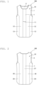
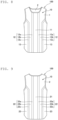
- FIG. 1 is a plan view of the shirt according to the embodiment of the present teaching when seen from a front section side.
- FIG. 2 is a plan view of the shirt according to the embodiment of the present teaching when seen from a back section side.
- a shirt 100 according to an embodiment of the present teaching is suitably used for sports with heavy perspiration amount, such as marathon.
- the shirt 100 includes a section body 10 including a front section 1 covering the front side of a wearer and a back section 2 covering the back side of the wearer.
- the fabric of the shirt 100 tends to come into intimate contact with the skin of a wearer. In such a situation, the shirt 100 according to the embodiment of the present teaching reduces adherence of the fabric to the skin.
- Conventional shirts take measures such as a chemical treatment such as a water repellent treatment on the surface of the fabric or having air vents penetrating the fabric from the front surface to the back surface in order to promote permeability. Since air vents promote permeability more greatly than a mesh fabric, a known shirt has air vents formed by cutting warp or weft treads of the fabric.
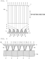
- ridge-shaped projections 4 and recesses 5 are alternately arranged in a knit fabric 40 constituting the low tack region t.
- the ridge-shaped projections 4 are located on a side to contact with a skin 10s.
- the ridge-shaped projections 4 in the low tack region t are arranged in the top-bottom direction of the section body 10.
- the low tack region t is composed of a combination of knitted fabrics with different skin-side surface shapes such that at least one of a width a of the ridge-shaped projections 4 or an interval x between the ridge-shaped projections 4 and 4 varies.
- the intervals between the ridge-shaped projections 4 of the ridge-shaped double raschel knit fabric 40 in the low tack region t are made smaller in an area of the body with a larger perspiration amount so that adherence of the fabric to the body when sweating can be thereby reduced.
- each of the back intermediate regions 22 is divided into three regions: a first intermediate region 22a located near the back center region 21; a third intermediate region 22c located near the side region 23; and a second intermediate region 22b located between the first intermediate region 22a and the third intermediate region 22c, and the first intermediate region 22a, the second intermediate region 22b, and the third intermediate region 22c have different surface shapes of the low tack region t.
- the ridge-shaped projections 4 of the double raschel knit fabric 40 shown in FIG. 10(c) have a wave pattern similar to FIG. 10(b) .
- the interval between adjacent ones of the ridge-shaped projections 4 in FIG. 10(c) is larger than that in FIG. 10(b)
- a wave span in FIG. 10(c) is wider than that in FIG. 10(b) .
- a width of the ridge-shaped projections 4 in FIG. 10(c) is larger than that of the ridge-shaped projections 4 in FIG. 10(b) .
- the ridge-shaped projections 4 of the double raschel knit fabric 40 shown in FIG. 10(d) have a wave pattern similar to those in FIGS. 10(b) and 10(c) .
- the orientation of the ridge herein is an orientation of the ridge in the longitudinal directions, and is the top-bottom directions in the drawing sheet in the case of FIG. 10(a) .
- the orientation of the ridge refers to the longitudinal directions when seen from a macroscopic overall point of view, and thus, the orientation of the ridge is also the top-bottom directions in the drawing sheet in this case.
- Each region of the shirt 100 according to the variation illustrated in FIGS. 8 and 9 uses the knit fabric 40 having the surface shape shown in one of FIGS. 10(a) through 10(d) .
- the section body 10 on the front section side shown in FIG. 8 is constituted by the front center region 11, the first intermediate regions 12a, the second intermediate regions 12b, the third intermediate regions 12c, and the side regions 13.
- the perspiration amount is large in the front center region 11 and the first intermediate regions 12a, and thus, the low tack region t with the surface shape of FIG. 10(a) is disposed in these regions.
- the perspiration amount in the second intermediate regions 12b is smaller than that in the front center region 11, and thus, the low tack region t with the surface shape of FIG.
- the low tack region t of FIG. 10(c) is disposed in the third intermediate regions 12c. Since the side regions 13 do not frequently contact the skin, the low tack region t with the surface shape of FIG. 10(d) having a maximum permeability is disposed.
- the section body 10 on the back section side shown in FIG. 9 is constituted by the back center region 21, the first intermediate regions 22a, the second intermediate regions 22b, the third intermediate regions 22c, and the side regions 23.
- the perspiration amount is large in the back center region 21, and thus, the low tack region t with the surface shape of FIG. 10(a) is disposed in the back center region 21.
- the perspiration amount in the first intermediate regions 22a is smaller than that in the back center region 21, and thus, the low tack region t with the surface shape of FIG. 10(b) is disposed in the first intermediate regions 22a.
- the perspiration amount in the second intermediate regions 22b is smaller than that in the first intermediate regions 22a, and thus, the low tack region t with the surface shape of FIG. 10(c) is disposed in the second intermediate regions 22b.
- the perspiration amount in the third intermediate regions 22c adjacent to the side regions 23 is smaller than that in the second intermediate regions 22b, in this variation, the low tack region t of FIG. 10(c) is disposed in the third intermediate regions 22c. Since the side regions 23 do not frequently contact the skin, the low tack region t with the surface shape of FIG. 10(d) having a maximum permeability is disposed.
- the low tack regions t having different surface shapes are disposed in accordance with the perspiration distribution of the human body so that reduction of adherence of the fabric when sweating and high permeability can be thereby obtained.
- the regions are configured with different knitted fabrics arranged side by side so that distortion and shrinkage of the knitted fabrics thereby tend to occur at the interface between the fabrics. Accordingly, a gap is formed between the body and the shirt 100 to serve as air vents and promote ventilation in the shirt 100 so that adherence of the fabric to the body due to sweating can be thereby reduced.
- a fabric has unevenness on the surface thereof, and thus, in contact between the fabric and skin, projections on the fabric surface are mainly in contact with skin.
- the fabric is modeled as a complex of the base fabric 3 and the ridge-shaped projections 4.
- a certain amount of air 51 is supplied to the contact interface, and water is supposed to be locally present in a columnar shape near the contact portion of the ridge-shaped projections 4 and the skin 10s.
- a meniscus occurring in a portion where the skin 10s, the water 50, and the air 51 contact causes a water pressure to be negative. Consequently, adherence is generated between the fabric and the skin.
- the phenomenon that the water pressure becomes negative is a state where water is trying to swallow everything in contact with the water. Accordingly, the fabric and the skin that are in contact with intervention of water are attracted to each other. This suggests that minimization of a projected area (cross-sectional area) of a region surrounded by the frame a in FIG. 12 (see FIG.
- an area ratio of projections occupying a fabric projected area is defined as an asperity area ratio.
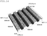
- a sample shown in the bird's-eye view of FIG. 14 was prepared to measure an asperity area ratio.
- a knitted fabric including ridge-shaped projections in which warp knitting was double raschel jacquard and braid knitting was a rib structure was formed using a material of 100% polyester yarn with a fineness: 56T/36F, 33T/12F with a double raschel machine with piezo jacquard technology.
- the base fabric includes ridge-shaped projections.
- a fabric surface of 10 mm square was measured with a three-dimensional shape measuring machine, and a height distribution (frequency distribution, histogram) was derived.
- the three-dimensional shape measuring machine herein was VR3000 manufactured by KEYENCE CORPORATION.
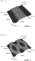
- the sample of FIG. 14 was measured, thereby obtaining FIGS. 15(a) and 15(b) .
- White regions in FIG. 15(a) are recesses, and a total area of the recesses is a left side of the histogram in FIG. 15(c) .
- White regions in FIG. 15(b) are projections, and a total area of the projections corresponds to a right side of the histogram in FIG. 15(c) .
- a sensory test was conducted with a device shown in a schematic view of FIG. 30 .
- a fabric sample cut into 100 mm ⁇ 30 mm was placed on the inner side of the left upper arm of each subject, and as shown in FIG. 30 , a fabric sample 100S was connected to a weight 104 of 100 g using a clip 101, nylon yarn (No. 0.1) 102, and pulleys 103. Then, the fabric sample was detached from the skin by a free fall of the weight 104. The tackiness at this time was evaluated by the subjects on a 5-point scale (minimum tackiness: 5 points, maximum tackiness: 1 point).
- Table 1 and FIG. 31 show an asperity area ratio of each fabric sample and sensory test results.
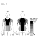
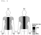
- thermomapping shown in FIG. 5 and the human body perspiration rate distribution diagram shown in FIG. 6 , it is supposed that thermal stress is highest in a front center upper portion and a back center portion of the human body.
- a textile with an asperity area ratio of 15% or less is preferably disposed in this region.
- a textile with an asperity area ratio of 25% or less is preferably disposed in a region between these regions and the sides of the human body.
- the skin and the textile do not contact each other frequently, and thus, arrangement of the textile is not limited to this example.
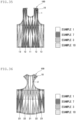
- FIG. 33 is a plan view of a shirt according to Specific Example 1 of the present teaching when seen from a front section side.
- FIG. 34 is a plan view of the shirt according to Specific Example 1 of the present teaching when seen from a back section side.
- FIGS. 33 and 34 different low tack regions t are disposed in a levee pattern in the front section 1 and the back section 2.
- the front section 1 includes the front center region 11, the side regions 13, and the front intermediate regions 12 between the front center region 11 and the side regions 13.
- Each of the front intermediate regions 12 is divided into three regions: the first intermediate region 12a located near the front center region 11; the third intermediate region 12c located near the side region 13; and the second intermediate region 12b located between the first intermediate region 12a and the third intermediate region 12c.
- Each of the side regions 13 is divided into two regions: a first side region 13a adjacent to the third intermediate region 12c; and the second side region 13b adjacent to the first side region 13a.
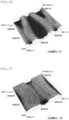
- Example 1 uses a double raschel knit fabric constituting low tack regions t with four patterns of surface shapes: the surface shape of Example 1 (see FIG. 18 ) used as the fabric sample described above; the surface shape of Example 3 (see FIG. 20 ); the surface shape of Example 7 (see FIG. 24 ); and the surface shape of Example 10 (see FIG. 27 ).
- Example 1 is indicated as hollow areas
- Example 3 is indicated by hatching
- Example 7 is indicated by cross hatching
- Example 10 is indicated by hatching with broken lines.
- the low tack regions t are arranged in the following manner.
- the perspiration amount is large in the front center region 11, the first intermediate regions 12a, and the second intermediate regions 12b.
- the front section 1 takes into consideration adherence of the fabric to the body. Therefore, the same fabric is used in the front center region 11 and the second intermediate regions 12b, and a different fabric is used in the first intermediate regions 12a. Accordingly, the low tack region t with the surface shape of Example 1 is disposed in the front center region 11 and the second intermediate regions 12b a.
- the low tack region t with the surface shape of Example 7 which has a small water retention is disposed in the first intermediate regions 12a.
- the perspiration amount in the third intermediate regions 12c adjacent to the side regions 13 is smaller than that in the front center region 11, and thus, the low tack region t of the surface shape Example 3 is disposed in the third intermediate regions 12c. Since the second side regions 13b do not frequently contact the skin, the low tack region t with the surface shape of Example 10 having a maximum permeability is disposed in the second side regions 13b. In the first side regions 13a, the low tack region t with the surface shape of Example 7 is disposed.
- the front section 1 of the section body 10 includes the front center region 11, the side regions 13 covering side portions of the wearer, and the front intermediate regions 12 between the front center region 11 and the side regions 13.
- each of the front intermediate regions 12 a plurality of low tack regions t each with the surface shape of Example 1 having a diamond shape in plan view are arranged, and low tack regions t each with the surface shape of Example 7 having a diamond shape in plan view are arranged to be adjacent to the low tack regions t of Example 1.
- the low tack regions t each with the surface shape of Example 3 having a diamond shape in plan view and low tack regions t each with the surface shape of Example 7 having a diamond shape in plan view are arranged.
- the low tack regions t having different surface shapes are disposed in accordance with the perspiration distribution of the human body so that reduction of adherence of the fabric when sweating and high permeability can be thereby obtained.
- the wetness degree of the shirt was evaluated on a 4-point scale through a questionnaire format rated by the subjects with the following ratings: 4: Wet, 3: Damp, 2: Partially damp, and 1: Dry.
- Table 3 shows measurement results.
- the numbers “1” to “4" represent evaluation of the wetness degree of the shirt, while “ ⁇ ,” “ ⁇ ,” and “ ⁇ ” represent evaluation of the degree of adherence of the shirt to the skin. Sections representing none of “ ⁇ ,” “A,” and “ ⁇ ,” correspond to the aforementioned “None” in evaluation on the degree of adherence of the shirt to the skin.
- a knitted fabric in which the fabric surface is subjected to water repellent finish may be used.
- the surface shape of a knitted fabric that does not contact the skin is not limited.
- chemical compositions of the fabric monomer types and ratios, polymer types and ratios, molecular weight, straight or branched chains, purity, moisture content, viscoelasticity, and wettability based on chemical composition
- single fiber properties cross-sectional shape, cross-sectional area, fiber length, straight/crimped, and surface roughness of the sides
- spinning conditions single fiber count, short fiber density, twist angle, and friction coefficient between short fibers
- fabric structure type and ratio of yarns, yarn spatial distribution, fabric thickness, and fabric rigidity
- air vents penetrating the fabric may be provided.
- a fabric dyed with a dye including a supercritical fluid dyeing may be used.
- a low tack region may be provided in a garment to contact with a human skin, other than the shirt.
- a low tack region may be used for short pants, leggings, long pants, skorts, one-piece dresses, and other similar items.
- the present teaching is applicable to sport shirts such as running shirts.
Landscapes
- Engineering & Computer Science (AREA)
- Textile Engineering (AREA)
- Health & Medical Sciences (AREA)
- General Health & Medical Sciences (AREA)
- Physical Education & Sports Medicine (AREA)
- Chemical & Material Sciences (AREA)
- Materials Engineering (AREA)
- Knitting Of Fabric (AREA)
- Details Of Garments (AREA)
Abstract
Description
- The present teaching relates to a shirt.
- In sports such as marathon, the fabric of a shirt tends to come into intimate contact with the skin of a wearer when sweating. In such a situation, adherence and separation of the skin and the fabric repeatedly occur. This causes discomfort of the wearer.
- It is therefore desired to place, in an appropriate area of a shirt, a fabric having low adherence with skin even when sweating.
- Conventionally, shirts used for sports such as marathon are subjected to a chemical treatment such as a water repellent treatment on the fabric surface and/or having air vents for promoting permeability.
- However, in a shirt made of a fabric subjected to a chemical treatment such as a water repellent treatment on the fabric surface and/or having air vents for promoting permeability, in the case of reaching a perspiration amount over maximum water retention of the shirt, a contact interface between the skin of a wearer and the fabric is filled with water (sweat) to thereby generate a large adherence. Accordingly, the fabric sticks to the skin, which causes discomfort of the wearer.
- A garment incorporating a double raschel knit fabric in all or part of its fabric is also proposed (see Patent Literature 1).
Patent Literature 1 describes that an upper garment or pants entirely or partially incorporate a double raschel knit fabric in which a surface mesh fabric knitted into a coarse mesh and a backside mesh fabric knitted into a fine mesh are united such that monofilament connecting fibers are moved back and forth between the surface mesh fabric and the backside mesh fabric to thereby form a buffer clearance for obtaining permeability between the surface mesh fabric and the backside mesh fabric. The backside mesh fabric is designed to obtain a water absorption function of quickly absorbing sweat of a wearer or supplied moisture by a capillary action and retaining water. The buffer clearance in the surface material is designed to block water moving from the backside mesh fabric to the surface mesh fabric. - Patent Literature:
Japanese Patent Application Laid-Open No. 2015-78450 - The technique described in
Patent Literature 1 is intended to absorb and retain water in sweating. Thus, also inPatent Literature 1, in the case of reaching a perspiration amount over maximum water retention, the fabric sticks to the skin of a wearer, which also causes discomfort of the wearer. - It is therefore an object of the present teaching to provide a shirt that reduces adherence of fabric to skin when sweating and does not cause discomfort of a wearer.
- Inventors of the present teaching studied a surface shape of a fabric that can reduce adherence even in a case where water is present at the interface between skin and the fabric. Through an intensive study, the inventors have reached the following configurations.
- A shirt according to one embodiment of the present teaching is a shirt including a section body, and the section body includes a front section covering a front side of a wearer and a back section covering a back side of the wearer, wherein at least one of the front section or the back section includes a low tack region composed of a knitted fabric including ridge-shaped projections, and the low tack region is disposed such that the ridge-shaped projections are located on a side to contact skin of the wearer and extends in top-bottom direction of the section body.
- In the following description, numerous specific examples are set forth in order to provide a thorough understanding of the present teaching. It is obvious that those skilled in the art, however, would be able to carry out the present teaching without these specific examples.
- The following disclosure is to be, therefore, considered as an exemplification of the present teaching, and is not intended to limit the present teaching to the specific embodiments illustrated by the figures or description below.
- According to one embodiment of the present teaching, since the ridge-shaped projections are present on the front side of the body, only the ridge-shaped projections substantially contact the skin so that the contact area with the skin is small, and adherence to the fabric when sweating can be reduced. In addition, since the ridge-shaped projections are arranged in the top-bottom direction of the section body, sweat in perspiration tends to easily flow in the gravity direction, and accumulation of sweat is reduced. This can reduce adherence to the fabric.
-
- [
FIG. 1] FIG. 1 is a plan view of a shirt according to an embodiment of the present teaching when seen from a front section side. - [
FIG. 2] FIG. 2 is a plan view of the shirt according to the embodiment of the present teaching when seen from a back section side. - [
FIG. 3] FIG. 3 is a schematic view of a ridge-shaped knitted fabric used for a low tack region of the shirt according to the embodiment of the present teaching. - [
FIG. 4] FIG. 4 is a schematic view illustrating a state of the low tack region of the shirt according to the embodiment of the present teaching and skin. - [
FIG. 5] FIG. 5 is a human body thermomapping diagram, (a) shows a front side, and (b) shows a back side. - [
FIG. 6] FIG. 6 is a human body perspiration rate distribution diagram, (a) shows the front side, and (b) shows the back side. - [
FIG. 7] FIG. 7 is a schematic view of a knitted fabric combining low tack regions with different surface shapes. - [
FIG. 8] FIG. 8 is a plan view of a shirt according to a variation of the embodiment of the present teaching when seen from a front section side. - [
FIG. 9] FIG. 9 is a plan view of the shirt according to the variation of the embodiment of the present teaching when seen from a back section side. - [
FIG. 10] FIG. 10 shows plan views illustrating examples of knitted fabrics each having ridge-shaped projections used in the present teaching on one side, and (a) to (d) show four different surface shapes. - [
FIG. 11] FIG. 11 is a schematic view showing a relationship between projections and a base fabric when the knitted fabric is taken along the top-bottom directions. - [
FIG. 12] FIG. 12 is a schematic view illustrating a state of a low tack region of the shirt according to the embodiment of the present teaching and skin. - [
FIG. 13] FIG. 13 is an enlarged view of a portion enclosed by a rectangle a inFIG. 12 . - [
FIG. 14] FIG. 14 is a bird's-eye view of a sample of a ridge-shaped double raschel knit fabric which applies to the present teaching. - [
FIG. 15] FIG. 15 shows height distributions as results obtained by measuring the fabric surface shown inFIG. 14 with a three-dimensional measuring machine, (a) shows recesses, (b) shows projections, and (c) shows a frequency distribution histogram. - [
FIG. 16] FIG. 16 is a bird's-eye view of a sample of a double raschel knit fabric according to Comparative Example 1. - [
FIG. 17] FIG. 17 is a bird's-eye view of a sample of a double raschel knit fabric according to Comparative Example 2. - [
FIG. 18] FIG. 18 is a bird's-eye view of a sample of a ridge-shaped double raschel knit fabric according to Example 1 of the present teaching. - [
FIG. 19] FIG. 19 is a bird's-eye view of a sample of a ridge-shaped double raschel knit fabric according to Example 2 of the present teaching. - [
FIG. 20] FIG. 20 is a bird's-eye view of a sample of a ridge-shaped double raschel knit fabric according to Example 3 of the present teaching. - [
FIG. 21] FIG. 21 is a bird's-eye view of a sample of a ridge-shaped double raschel knit fabric according to Example 4 of the present teaching. - [
FIG. 22] FIG. 22 is a bird's-eye view of a sample of a ridge-shaped double raschel knit fabric according to Example 5 of the present teaching. - [
FIG. 23] FIG. 23 is a bird's-eye view of a sample of a ridge-shaped double raschel knit fabric according to Example 6 of the present teaching. - [
FIG. 24] FIG. 24 is a bird's-eye view of a sample of a ridge-shaped double raschel knit fabric according to Example 7 of the present teaching. - [
FIG. 25] FIG. 25 is a bird's-eye view of a sample of a ridge-shaped double raschel knit fabric according to Example 8 of the present teaching. - [
FIG. 26] FIG. 26 is a bird's-eye view of a sample of a ridge-shaped double raschel knit fabric according to Example 9 of the present teaching. - [
FIG. 27] FIG. 27 is a bird's-eye view of a sample of a ridge-shaped double raschel knit fabric according to Example 10 of the present teaching. - [
FIG. 28] FIG. 28 is a bird's-eye view of a sample of a ridge-shaped double raschel knit fabric according to Example 11 of the present teaching. - [
FIG. 29] FIG. 29 is a bird's-eye view of a sample of a ridge-shaped double raschel knit fabric according to Example 12 of the present teaching. - [
FIG. 30] FIG. 30 is a schematic view of a device used for conducting a sensory test of the present teaching. - [
FIG. 31] FIG. 31 is a graph showing a relationship between an asperity area ratio and a sensory value. - [
FIG. 32] FIG. 32 is a graph showing a relationship between a root mean square height and a water retention. - [
FIG. 33] FIG. 33 is a plan view of a shirt according to Specific Example 1 of the present teaching when seen from a front section side. - [
FIG. 34] FIG. 34 is a plan view of the shirt according to Specific Example 1 of the present teaching when seen from a back section side. - [
FIG. 35] FIG. 35 is a plan view of a shirt according to Specific Example 2 of the present teaching when seen from a front section side. - [
FIG. 36] FIG. 36 is a plan view of the shirt according to Specific Example 2 of the present teaching when seen from a back section side. - A shirt according to an embodiment of the present teaching will now be described in detail. The shirt according to the present teaching is not limited to that described in the following embodiment, and can be carried out with an appropriate change without departing from the gist of the teaching.
-
FIG. 1 is a plan view of the shirt according to the embodiment of the present teaching when seen from a front section side.FIG. 2 is a plan view of the shirt according to the embodiment of the present teaching when seen from a back section side. Ashirt 100 according to an embodiment of the present teaching is suitably used for sports with heavy perspiration amount, such as marathon. Theshirt 100 includes asection body 10 including afront section 1 covering the front side of a wearer and aback section 2 covering the back side of the wearer. When sweating, the fabric of theshirt 100 tends to come into intimate contact with the skin of a wearer. In such a situation, theshirt 100 according to the embodiment of the present teaching reduces adherence of the fabric to the skin. - Conventional shirts take measures such as a chemical treatment such as a water repellent treatment on the surface of the fabric or having air vents penetrating the fabric from the front surface to the back surface in order to promote permeability. Since air vents promote permeability more greatly than a mesh fabric, a known shirt has air vents formed by cutting warp or weft treads of the fabric.
- From a viewpoint different from the water repellent treatment and permeability, the inventors of the present application studied reduction of adherence of the
shirt 100 to skin even in a state where water is present at the interface between the skin and the fabric. Consequently, the inventors found that adherence of the fabric to the skin can be reduced even in a state where water is present at the interface between the skin and the fabric by optimizing the surface shape of the fabric. This adherence reduction can suppress movement of moisture due to sweating into the fabric. This eliminates the necessity for increasing maximum water retention of the fabric. Conventionally, moisture generated by perspiration is moved into the fabric and vaporized to be released to the outside. Thus, in the case of exceeding the maximum water retention, the fabric adheres to the skin. To prevent this, the maximum water retention needs to be as large as possible. - As described above, the
shirt 100 does not need to have large maximum water retention of the fabric, and thus, the maximum water retention directly related to a wet shirt weight can be reduced so that the weight of the wet shirt can be reduced. - In the
shirt 100, a low tack region having obtained low tackiness by optimizing the surface shape of the fabric is disposed in at least one of thefront section 1 or theback section 2. - The tackiness herein refers to adherence of the fabric to the skin of a wearer. The low tack region refers to a region where adherence of the fabric to the skin is reduced.
- As illustrated in
FIGS. 1 and 2 , in this embodiment, a low tack region t is disposed in afront center region 11 extending in the top-bottom direction in a center portion of thefront section 1, and a low tack region t is disposed in aback center region 21 extending in the top-bottom direction in a center portion of theback section 2. - As illustrated in
FIG. 3 , in aknit fabric 40 constituting the low tack region t, ridge-shapedprojections 4 and recesses 5 are alternately arranged. As illustrated inFIG. 4 , the ridge-shapedprojections 4 are located on a side to contact with askin 10s. The ridge-shapedprojections 4 in the low tack region t are arranged in the top-bottom direction of thesection body 10. - The
knit fabric 40 used in the low tack region t of theshirt 100 can be, for example, a ridge-shaped doubleraschel knit fabric 40 as illustrated inFIG. 3 . The ridge-shaped double raschel knit fabric 40is configured such that the ridge-shapedprojections 4 shaped by coupling a back-side fabric 4a to contact theskin 10s and a front-side base fabric 3 and therecesses 5 composed of thebase fabric 3 are alternately arranged. In this embodiment, thebase fabric 3 is a mesh fabric to have high permeability. - As illustrated in
FIGS. 3 and 4 , the ridge-shaped doubleraschel knit fabric 40 including the ridge-shapedprojections 4 is mainly composed of the back-side fabric 4a, thebase fabric 3, and connectingthreads 6. The back-side fabric 4a is formed by knitting threads constituting the back surface. The back-side fabric 4a is on the skin side of the garment. Thebase fabric 3 is formed by knitting threads constituting the front surface. The connectingthreads 6 run substantially in the longitudinal direction (thickness direction) between the back-side fabric 4a and thebase fabric 3 to fill a gap between the back-side fabric 4a and thebase fabric 3 and connects the back-side fabric 4a and thebase fabric 3 together. The connectingthreads 6 provide thickness of the doubleraschel knit fabric 40. - The ridge-shaped
projections 4 and therecesses 5 of the ridge-shaped doubleraschel knit fabric 40 according to this embodiment function such that the surface shape constituted by the ridge-shapedprojections 4 and therecesses 5 reduces adherence. To achieve this function, the ridge-shaped doubleraschel knit fabric 40 in which the asperity area ratio and the root mean square height of the projections in the fabric are set is used. Accordingly, the height of the ridge-shapedprojections 4 of the ridge-shaped doubleraschel knit fabric 40 according to this embodiment is different from heights of ridge-shaped projections of conventional ridge-shaped double raschel knit fabrics in which the heights of ridge-shaped projections were set to cause the region of the recesses to function as a ventilation region. The surface shape, the asperity area ratio, and the root mean square height of the projections for reducing adherence will be described later. - As illustrated in
FIG. 4 , in this embodiment, since the ridge-shapedprojections 4 are located on the front side of the body, only the ridge-shapedprojections 4 substantially contact theskin 10s. Accordingly, the contact area with theskin 10s is small so that adherence to the fabric when sweating can be reduced. In addition, since the ridge-shapedprojections 4 are arranged in the top-bottom direction of the section body, sweat due to perspiration easily flows in the gravity direction. This suppresses accumulation of sweat to thereby reduce adherence to the fabric. - The low tack region t provided in the
shirt 100 is preferably located in an area of the body with a large perspiration amount.FIG. 5 shows a human body thermomapping diagram.FIG. 6 shows a human body perspiration rate distribution diagram. FromFIGS. 5 and6 , thermal stress is supposed to be highest in an upper portion of a front center portion and a back center portion of the human body. As shown inFIG. 6 , the perspiration amount is large in the front center portion and the back center portion of the human body. Accordingly, the presence of the low tack region t in a region with a large perspiration amount can reduce adherence of the fabric to the skin when sweating. - The
section body 10 includes thefront center region 11 extending in the top-bottom direction in a center portion of thefront section 1 and theback center region 21 extending in the top-bottom direction in a center portion of theback section 2. The low tack region t is preferably located in at least one of the upper portion of thefront center region 11 or theback center region 21 where thermal stress is supposed to be highest. InFIGS. 1 and 2 , the low tack region t is located in each of the upper portion of thefront center region 11 and theback center region 21. Although the low tack region t is located in the upper portion of thefront center region 11 inFIG. 1 , the low tack region t may be provided in the entirefront center region 11. The upper portion of thefront center region 11 refers to a region of an upper half of thefront center region 11 when thefront center region 11 is divided into an upper portion and a lower portion. - In this embodiment, in the ridge-shaped double
raschel knit fabric 40 used in the low tack region t, thebase fabric 3 is composed of a mesh fabric. Thebase fabric 3 of the doubleraschel knit fabric 40 is composed of a mesh fabric with high permeability to have high permeability so that air in theshirt 100 can be easily released to the outside. Accordingly, heat dissipation in theshirt 100 is enhanced, and sweat in a gas phase is released to the outside through the mesh fabric with high permeability so that the fabric can be thereby easily dried. - As shown in the human body perspiration rate distribution diagrams of
FIG. 6 , the perspiration amount of the human body varies among areas. The surface shape of the fabric of the doubleraschel knit fabric 40 on the skin side is preferably caused to vary depending on the perspiration amount. For example, in side portions of the human body, since the skin and the fabric less contact each other, an importance is placed on permeability, and an interval x between the ridge-shapedprojections base fabric 3. Accordingly, in this embodiment, as shown inFIG. 7 , the low tack region t is composed of a combination of knitted fabrics with different skin-side surface shapes such that at least one of a width a of the ridge-shapedprojections 4 or an interval x between the ridge-shapedprojections - With a combination of knitted fabrics in which at least one of the width a of the ridge-shaped
projections 4 that provided to be orthogonal to the top-bottom directions of thesection body 10 or the interval between the ridge-shapedprojections shirt 100 to serve as air vents, and ventilation in theshirt 100 is promoted so that adherence of the fabric to the body due to sweating can be thereby reduced. - As illustrated in
FIG. 1 , thefront section 1 of thesection body 10 includes, as regions other than thefront center region 11,side regions 13 covering side portions of the wearer and frontintermediate regions 12 between thefront center region 11 and theside regions 13. In theshirt 100, all thefront center region 11, the frontintermediate regions 12, and theside regions 13 are composed of low tack regions t, but each interval between adjacent ridge-shapedprojections shirt 100 satisfies x1 < x2 < x3, where x1 is an interval between adjacent ones of the ridge-shapedprojections front center region 11, x2 is an interval between adjacent ones of the ridge-shapedprojections intermediate regions 12, and x3 is an interval between adjacent ones of the ridge-shapedprojections side regions 13. - In this configuration, the intervals between the ridge-shaped
projections 4 of the ridge-shaped doubleraschel knit fabric 40 in the low tack region t are made smaller in an area of the body with a larger perspiration amount so that adherence of the fabric to the body when sweating can be thereby reduced. - In addition, the
front center region 11, the frontintermediate regions 12, and theside regions 13 are configured with different knitted fabrics being arranged side by side so that distortion and shrinkage of the fabrics thereby tend to occur at the interface between the fabrics. Accordingly, a gap is formed between the body and theshirt 100 to serve as air vents, and ventilation in theshirt 100 is promoted so that adherence of the fabric to the body due to sweating can be thereby reduced. - As illustrated in
FIG. 2 , theback section 2 of thesection body 10 includes, as regions other than theback center region 21 andside regions 23, backintermediate regions 22 between theback center region 21 and theside regions 23. In theshirt 100, all theback center region 21, the backintermediate regions 22, and theside regions 23 are composed of low tack regions t, but each interval between adjacent ridge-shapedprojections shirt 100 satisfies x4 < x5 < x3, where x3 is an interval between adjacent ridge-shapedprojections side regions 23, x4 is an interval between adjacent ridge-shapedprojections back center region 21, and x5 is an interval between adjacent ridge-shapedprojections intermediate regions 22. - In this configuration, the intervals between the ridge-shaped
projections 4 of the ridge-shaped doubleraschel knit fabric 40 in the low tack region t are made smaller in an area of the body with a larger perspiration amount so that adherence of the fabric to the body when sweating can be thereby reduced. - In addition, the
back center region 21, the backintermediate regions 22, and theside regions 23 are configured with different knitted fabrics being arranged side by side so that distortion and shrinkage of the fabrics thereby tend to occur at the interface between the fabrics. Accordingly, a gap is formed between the body and theshirt 100 to serve as air vents, and ventilation in theshirt 100 is promoted so that adherence of the fabric to the body due to sweating can be thereby reduced. - A variation of this embodiment will now be described.
FIG. 8 is a plan view of a shirt according to a variation of the embodiment of the present teaching when seen from a front section side.FIG. 9 is a plan view of the shirt according to the variation of the embodiment of the present teaching when seen from a back section side. In this variation, each of the frontintermediate regions 12 is divided into three regions: a firstintermediate region 12a located near thefront center region 11; a thirdintermediate region 12c located near theside region 13; and a secondintermediate region 12b located between the firstintermediate region 12a and the thirdintermediate region 12c, and the firstintermediate region 12a, the secondintermediate region 12b, and the thirdintermediate region 12c have different surface shapes of the low tack region t. Similarly, each of the backintermediate regions 22 is divided into three regions: a firstintermediate region 22a located near theback center region 21; a thirdintermediate region 22c located near theside region 23; and a secondintermediate region 22b located between the firstintermediate region 22a and the thirdintermediate region 22c, and the firstintermediate region 22a, the secondintermediate region 22b, and the thirdintermediate region 22c have different surface shapes of the low tack region t. - Then, the surface shape of the double
raschel knit fabric 40 used in theshirt 100 according to this embodiment will be described.FIG. 10 shows plan views each showing an example of a knitted fabric having ridge-shaped projections on one side, andFIGS. 10(a) through 10(d) show four types of the surface shapes. Theseknitted fabrics 40 can use ridge-shaped double raschel knit fabrics in each of which the ridge-shapedprojections 4 shaped by coupling the back-side fabric to contact with the skin and the base fabric to each other and therecesses 5 composed of the base fabric are alternately arranged. InFIGS. 10(a) through 10(d) , the ridge-shapedprojections 4 are hatched for discrimination from therecesses 5. - The ridge-shaped
projections 4 and therecesses 5 of the doubleraschel knit fabric 40 shown inFIG. 10(a) have a substantially straight stripe pattern. The ridge-shapedprojections 4 of the doubleraschel knit fabric 40 shown inFIG. 10(b) have a wave pattern, and adjacent ones of the ridge-shapedprojections 4 are line symmetric with respect to the top-bottom directions of thesection body 10. A width of the ridge-shapedprojections 4 inFIG. 10(b) is larger than that of the ridge-shapedprojections 4 inFIG. 10(a) . Adjacent ones of the ridge-shapedprojections 4 are in contact with each other in portions where the ridge-shapedprojections 4 are close to each other. The ridge-shapedprojections 4 of the doubleraschel knit fabric 40 shown inFIG. 10(c) have a wave pattern similar toFIG. 10(b) . The interval between adjacent ones of the ridge-shapedprojections 4 inFIG. 10(c) is larger than that inFIG. 10(b) , and a wave span inFIG. 10(c) is wider than that inFIG. 10(b) . A width of the ridge-shapedprojections 4 inFIG. 10(c) is larger than that of the ridge-shapedprojections 4 inFIG. 10(b) . The ridge-shapedprojections 4 of the doubleraschel knit fabric 40 shown inFIG. 10(d) have a wave pattern similar to those inFIGS. 10(b) and 10(c) . The interval between the adjacent ridge-shapedprojections 4 inFIG. 10(d) is larger than that inFIG. 10(c) , and a wave span inFIG. 10(d) is wider than that inFIG. 10(c) . A width of the ridge-shapedprojections 4 inFIG. 10(d) is larger than that of ridge-shapedprojections 4 inFIG. 10(c) . - In the knitted fabrics of
FIGS. 10(a) through 10(d) , the knitted fabric shown inFIG. 10(a) is used in the low tack region t disposed in a region with a largest perspiration amount, and the knitted fabrics ofFIGS. 10(b) through 10(d) whose wave patterns gradually become larger in this order are sequentially used as the perspiration amount decreases. With this configuration, the low tack regions t are disposed in accordance with the perspiration amount of the human body so that reduction of adherence to the skin by the ridge-shapedprojections 4 and permeability by thebase fabric 3 can be obtained in accordance with the perspiration amount. -
FIG. 11 shows a relationship between the ridge-shapedprojections 4 and thebase fabric 3 when theknit fabric 40 is taken along the top-bottom directions. As illustrated inFIG. 11 , the surface of the ridge-shapedprojections 4 on the side of the body have different heights such that the surface of the ridge-shapedprojections 4 becomes wavelike in the top-bottom direction with respect to the body of the wearer in an upright posture. That is, a gap is provided between the ridge-shapedprojections 4 and thebase fabric 3. In this manner, theknit fabric 40 in which the ridge-shapedprojections 4 have different heights so as to from wavelike surface in the top-bottom direction with respect to the body of the wearer may be used. For example, theknit fabric 40 shown inFIG. 10(d) may have the ridge-shapedprojections 4 as illustrated inFIG. 11 . The use of such aknit fabric 40 for the sides of the human body enhances air permeability. This can promote ventilation inside theshirt 100. - In
FIG. 10 , the ridge-shapedprojections 4 are continuous in the longitudinal direction thereof, but may not be continuous and the ridge-shapedprojections 4 may have small slits in a relatively small area ratio. That is, the ridge may have slits as long as the ridge does not have a spotted uneven pattern and has a substantially ridge shape. - The orientation of the ridge herein is an orientation of the ridge in the longitudinal directions, and is the top-bottom directions in the drawing sheet in the case of
FIG. 10(a) . Even in the case where the ridge-shaped projections have a wave pattern, as inFIGS. 10(b) through 10(d) , the orientation of the ridge refers to the longitudinal directions when seen from a macroscopic overall point of view, and thus, the orientation of the ridge is also the top-bottom directions in the drawing sheet in this case. - The top-bottom directions of the
section body 10 herein include the lengthwise directions (perpendicular direction of the shirt and also includes a case where the directions tilt within an angle range of ±45 degrees from the lengthwise directions of the shirt. However, the angle of the top-bottom directions to the direction along the perpendicular directions of the shirt is preferably as small as possible. - Each region of the
shirt 100 according to the variation illustrated inFIGS. 8 and 9 uses theknit fabric 40 having the surface shape shown in one ofFIGS. 10(a) through 10(d) . Thesection body 10 on the front section side shown inFIG. 8 is constituted by thefront center region 11, the firstintermediate regions 12a, the secondintermediate regions 12b, the thirdintermediate regions 12c, and theside regions 13. The perspiration amount is large in thefront center region 11 and the firstintermediate regions 12a, and thus, the low tack region t with the surface shape ofFIG. 10(a) is disposed in these regions. The perspiration amount in the secondintermediate regions 12b is smaller than that in thefront center region 11, and thus, the low tack region t with the surface shape ofFIG. 10(b) is disposed in the secondintermediate regions 12b. The perspiration amount in the thirdintermediate regions 12c adjacent to theside regions 13 is smaller than that in the firstintermediate regions 12a, and thus, the low tack region t ofFIG. 10(c) is disposed in the thirdintermediate regions 12c. Since theside regions 13 do not frequently contact the skin, the low tack region t with the surface shape ofFIG. 10(d) having a maximum permeability is disposed. - Similarly, the
section body 10 on the back section side shown inFIG. 9 is constituted by theback center region 21, the firstintermediate regions 22a, the secondintermediate regions 22b, the thirdintermediate regions 22c, and theside regions 23. In this variation, the perspiration amount is large in theback center region 21, and thus, the low tack region t with the surface shape ofFIG. 10(a) is disposed in theback center region 21. The perspiration amount in the firstintermediate regions 22a is smaller than that in theback center region 21, and thus, the low tack region t with the surface shape ofFIG. 10(b) is disposed in the firstintermediate regions 22a. The perspiration amount in the secondintermediate regions 22b is smaller than that in the firstintermediate regions 22a, and thus, the low tack region t with the surface shape ofFIG. 10(c) is disposed in the secondintermediate regions 22b. Although the perspiration amount in the thirdintermediate regions 22c adjacent to theside regions 23 is smaller than that in the secondintermediate regions 22b, in this variation, the low tack region t ofFIG. 10(c) is disposed in the thirdintermediate regions 22c. Since theside regions 23 do not frequently contact the skin, the low tack region t with the surface shape ofFIG. 10(d) having a maximum permeability is disposed. - In this manner, the low tack regions t having different surface shapes are disposed in accordance with the perspiration distribution of the human body so that reduction of adherence of the fabric when sweating and high permeability can be thereby obtained.
- In addition, the regions are configured with different knitted fabrics arranged side by side so that distortion and shrinkage of the knitted fabrics thereby tend to occur at the interface between the fabrics. Accordingly, a gap is formed between the body and the
shirt 100 to serve as air vents and promote ventilation in theshirt 100 so that adherence of the fabric to the body due to sweating can be thereby reduced. - Next, the present teaching will be further described based on specific examples.
- In general, a fabric has unevenness on the surface thereof, and thus, in contact between the fabric and skin, projections on the fabric surface are mainly in contact with skin. As illustrated in
FIG. 12 , the fabric is modeled as a complex of thebase fabric 3 and the ridge-shapedprojections 4. Consider a case where the fabric and skin are repeatedly separated with motion of a wearer while the contact interface is filled withwater 50 by sweating or the like. - In this case, as illustrated in
FIGS. 12 and 13 , a certain amount ofair 51 is supplied to the contact interface, and water is supposed to be locally present in a columnar shape near the contact portion of the ridge-shapedprojections 4 and theskin 10s. A meniscus occurring in a portion where theskin 10s, thewater 50, and theair 51 contact causes a water pressure to be negative. Consequently, adherence is generated between the fabric and the skin. The phenomenon that the water pressure becomes negative is a state where water is trying to swallow everything in contact with the water. Accordingly, the fabric and the skin that are in contact with intervention of water are attracted to each other. This suggests that minimization of a projected area (cross-sectional area) of a region surrounded by the frame a inFIG. 12 (seeFIG. 13 ) leads to minimization of adherence. Thus, this is inferred that when the total number of ridge-shapedprojections 4 in contact with theskin 10s and the total cross-sectional area are minimized, the cross-sectional area of thecolumnar water 50 is minimized. - In view of this, the inventors of the present teaching focused on a total cross-sectional area of projections of the fabric in contact with skin as a design parameter of a low tackiness fabric. Here, an area ratio of projections occupying a fabric projected area is defined as an asperity area ratio. A sample shown in the bird's-eye view of
FIG. 14 was prepared to measure an asperity area ratio. - As the sample shown in
FIG. 14 , a knitted fabric including ridge-shaped projections in which warp knitting was double raschel jacquard and braid knitting was a rib structure was formed using a material of 100% polyester yarn with a fineness: 56T/36F, 33T/12F with a double raschel machine with piezo jacquard technology. - As shown in the bird's-eye view of
FIG. 14 , in the double raschel knit fabric, the base fabric includes ridge-shaped projections. As shown inFIG. 14 , a fabric surface of 10 mm square was measured with a three-dimensional shape measuring machine, and a height distribution (frequency distribution, histogram) was derived. The three-dimensional shape measuring machine herein was VR3000 manufactured by KEYENCE CORPORATION. The sample ofFIG. 14 was measured, thereby obtainingFIGS. 15(a) and 15(b) . White regions inFIG. 15(a) are recesses, and a total area of the recesses is a left side of the histogram inFIG. 15(c) . White regions inFIG. 15(b) are projections, and a total area of the projections corresponds to a right side of the histogram inFIG. 15(c) . - Thereafter, samples shown in the bird's-eye views of
FIGS. 16 through 29 were formed by using the same material with the same machine as those of the sample shown in the bird's-eye view ofFIG. 14 . Comparative Example 1 is a mesh structure. In Comparative Example 2 and Examples 1 through 12, braid knitting is a rib structure. - Five different fabrics shown in Table 1 were measured as fabric samples. In many fabric samples, peaks individually corresponding to projections and the base surface (recesses) were observed. Here, an area ratio of a region (projection region supposed to contact skin) higher than a median of peaks corresponding to projections is defined as an asperity area ratio.
- A sensory test was conducted on tackiness (adherence) to the five fabric samples prepared in the manner as described above.
- Subjects were six healthy adults aged to 30 to 60 years, four males and two females, and a process of placing each fabric sample on the skins of the subjects and detaching the fabric sample was performed, and at each time, the stickiness was sensuously evaluated in five stages of 1 to 5. As the number increases, tackiness decreases, that is, stickiness decreases.
- A sensory test was conducted with a device shown in a schematic view of
FIG. 30 . A fabric sample cut into 100 mm × 30 mm was placed on the inner side of the left upper arm of each subject, and as shown inFIG. 30 , a fabric sample 100S was connected to aweight 104 of 100 g using aclip 101, nylon yarn (No. 0.1) 102, and pulleys 103. Then, the fabric sample was detached from the skin by a free fall of theweight 104. The tackiness at this time was evaluated by the subjects on a 5-point scale (minimum tackiness: 5 points, maximum tackiness: 1 point). - Each fabric sample 100S was allowed to stand in ion-exchanged water for 10 seconds or more immediately before the sensory test, and then was placed on the inner side of the left upper arm of each subject.
[Table 1] Asperity area ratio, % Tackiness sensory value Minimum tackiness : 5 point Maximum tackiness: 1 point Comparative Example 1 50.0 1.50 Comparative Example 2 25.3 2.00 Example 1 12.9 4.67 Example 2 14.9 4.17 Example 3 22.3 3.33 - Table 1 and
FIG. 31 show an asperity area ratio of each fabric sample and sensory test results. - Table 1 and
FIG. 31 confirm that as the asperity area ratio increases, the sensory value decreases. Based on a 2-sample t-test, Comparative Example 1 and Comparative Example 2 do not show a significant difference. On the other hand, it is determined that Comparative Example 2 and Example 3 show a significant difference. That is, it is suggested that tackiness decreases by setting the asperity area ratio less than 25.3%. Accordingly, a low tackiness fabric suitably has an asperity area ratio of 25% or less, preferably 15% or less, in a knitted fabric having ridge-shaped projections. - Then, a result of consideration on the surface shape of a fabric and a moisture content will be described. Fabric samples were planed using the materials and the knitting machine described above based on Comparative Examples 1 and 2 and Examples 1 through 12 shown in the bird's-eye views of
FIGS. 16 through 29 . - For each fabric sample shown in Table 2, a surface shape of 10-mm square was measured with a three-dimensional shape measuring machine of VR3000 manufactured by KEYENCE CORPORATION, and as a parameter of a surface roughness, a root mean square height Sq was calculated.
- From a mass change before and after each fabric sample (25 mm × 60 mm) was immersed in ion-exchanged water for 10 seconds, a water retention per a unit area was calculated.
[Table 2] Root mean square height Sq, µ m Water retention, µ g/mm2 Comparative Example 1 56.64 668.67 Comparative Example 2 99.32 66.40 Example 1 276.68 1.60 Example 2 287.26 6.13 Example 3 261.42 3.87 Example 4 373.97 2.93 Example 5 276.38 3.93 Example 6 279.14 2.53 Example 7 310.76 1.20 Example 8 315.19 4.80 Example 9 357.95 4.80 Example 10 357.78 4.13 Example 11 359.73 3.00 Example 12 236.46 3.07 -
FIG. 32 and Table 2 show a relationship between the root mean square height Sq and the water retention. As the root mean square height Sq increased, the water retention decreased. From the viewpoint of achieving weight reduction of the shirt when sweating, it is determined to be preferable that the root mean square height Sq is 100 µm or more and 1000 µm or less, preferably 200 µm or more and 1000 µm or less. - Next, the position of the low tack region with respect to the
section body 10 will be further described. From the human body thermomapping shown inFIG. 5 and the human body perspiration rate distribution diagram shown inFIG. 6 , it is supposed that thermal stress is highest in a front center upper portion and a back center portion of the human body. A textile with an asperity area ratio of 15% or less is preferably disposed in this region. In addition, in a region between these regions and the sides of the human body, slight adherence between skin and the textile is expected, and thus, a textile with an asperity area ratio of 25% or less is preferably disposed. In the side portions of the human body, the skin and the textile do not contact each other frequently, and thus, arrangement of the textile is not limited to this example. - Specific examples of the present teaching will now be described.
FIG. 33 is a plan view of a shirt according to Specific Example 1 of the present teaching when seen from a front section side.FIG. 34 is a plan view of the shirt according to Specific Example 1 of the present teaching when seen from a back section side. - In
FIGS. 33 and 34 , different low tack regions t are disposed in a levee pattern in thefront section 1 and theback section 2. - As illustrated in
FIG. 33 , thefront section 1 includes thefront center region 11, theside regions 13, and the frontintermediate regions 12 between thefront center region 11 and theside regions 13. Each of the frontintermediate regions 12 is divided into three regions: the firstintermediate region 12a located near thefront center region 11; the thirdintermediate region 12c located near theside region 13; and the secondintermediate region 12b located between the firstintermediate region 12a and the thirdintermediate region 12c. Each of theside regions 13 is divided into two regions: afirst side region 13a adjacent to the thirdintermediate region 12c; and thesecond side region 13b adjacent to thefirst side region 13a. - Specific Example 1 uses a double raschel knit fabric constituting low tack regions t with four patterns of surface shapes: the surface shape of Example 1 (see
FIG. 18 ) used as the fabric sample described above; the surface shape of Example 3 (seeFIG. 20 ); the surface shape of Example 7 (seeFIG. 24 ); and the surface shape of Example 10 (seeFIG. 27 ). InFIGS. 33 and 34 , Example 1 is indicated as hollow areas, Example 3 is indicated by hatching, Example 7 is indicated by cross hatching, and Example 10 is indicated by hatching with broken lines. - The low tack regions t are arranged in the following manner. The perspiration amount is large in the
front center region 11, the firstintermediate regions 12a, and the secondintermediate regions 12b. Thefront section 1 takes into consideration adherence of the fabric to the body. Therefore, the same fabric is used in thefront center region 11 and the secondintermediate regions 12b, and a different fabric is used in the firstintermediate regions 12a. Accordingly, the low tack region t with the surface shape of Example 1 is disposed in thefront center region 11 and the secondintermediate regions 12b a. The low tack region t with the surface shape of Example 7 which has a small water retention is disposed in the firstintermediate regions 12a. The perspiration amount in the thirdintermediate regions 12c adjacent to theside regions 13 is smaller than that in thefront center region 11, and thus, the low tack region t of the surface shape Example 3 is disposed in the thirdintermediate regions 12c. Since thesecond side regions 13b do not frequently contact the skin, the low tack region t with the surface shape of Example 10 having a maximum permeability is disposed in thesecond side regions 13b. In thefirst side regions 13a, the low tack region t with the surface shape of Example 7 is disposed. - As illustrated in
FIG. 34 , theback section 2 is constituted by theback center region 21, theside regions 23, and the backintermediate regions 22 between theback center region 21 and theside regions 23. Each of the backintermediate regions 22 is divided into three regions: the firstintermediate region 22a located near theback center region 21; the thirdintermediate region 22c located near theside region 23; and the secondintermediate region 22b located between the firstintermediate region 22a and the thirdintermediate region 22c. Each of theside regions 23 is divided into two regions: thefirst side region 23a adjacent to the thirdintermediate region 22c; and thesecond side region 23b adjacent to thefirst side region 23a. - The low tack regions t are arranged in the following manner. The perspiration amount is large in the
back center region 21, and thus, the low tack region t with the surface shape of Example 1 is disposed in theback center region 21. The perspiration amount in the secondintermediate regions 22b is smaller than that in theback center region 21, and thus, the low tack region t with the surface shape of Example 3 is disposed in the secondintermediate regions 22b. Considering adherence of the fabric to the body, the low tack region t with the surface shape of Example 7 is disposed in the firstintermediate region 22a and the thirdintermediate regions 22c. Since thefirst side regions 23a do not frequently contact the skin, the low tack region t with the surface shape of Example 10 having a maximum permeability is disposed in thefirst side regions 23a. In thesecond side regions 23b, the low tack region t with the surface shape of Example 3 is disposed. - In this manner, the low tack regions t having different surface shapes are disposed in accordance with the perspiration distribution of the human body so that reduction of adherence of the fabric when sweating and high permeability can be thereby obtained.
- In addition, the regions are configured with different knitted fabrics arranged side by side so that distortion and shrinkage of the knitted fabrics thereby tend to occur at the interface between the fabrics. Accordingly, a gap is formed between the body and the
shirt 100 to serve as air vents and promote ventilation in theshirt 100 so that adherence of the fabric to the body due to sweating can be thereby reduced. - Wearing evaluation was conducted using Specific Example 1 of the present teaching. The wearing evaluation will be described later.
-
FIG. 35 is a plan view of a shirt according to Specific Example 2 of the present teaching when seen from a front section side.FIG. 36 is a plan view of the shirt according to Specific Example 2 of the present teaching when seen from a back section side. -
FIGS. 35 and 36 show mesh-like layouts in which low tack regions t with different diamond shapes are arranged in thefront section 1 and theback section 2 in the top-bottom direction and in the left-right directions. InFIGS. 35 and 36 , Example 1 is indicated as hollow areas, Example 3 is indicated by hatching, Example 7 is indicated by cross hatching, and Example 10 is indicated by hatching with broken lines. - The
front section 1 of thesection body 10 includes thefront center region 11, theside regions 13 covering side portions of the wearer, and the frontintermediate regions 12 between thefront center region 11 and theside regions 13. - In Specific Example 2, in the
front center region 11, a plurality of low tack regions t each with the surface shape of Example 1 having a diamond shape in plan view are arranged, and low tack regions t each with the surface shape of Example 7 having a diamond shape in plan view are arranged to be adjacent to the low tack regions t of Example 1. In thefront center region 11, the low tack regions t of Example 1 are occupying the largest total area . - In each of the front
intermediate regions 12, a plurality of low tack regions t each with the surface shape of Example 1 having a diamond shape in plan view are arranged, and low tack regions t each with the surface shape of Example 7 having a diamond shape in plan view are arranged to be adjacent to the low tack regions t of Example 1. In addition, in the frontintermediate regions 12 adjacent to thefront side regions 13, the low tack regions t each with the surface shape of Example 3 having a diamond shape in plan view and low tack regions t each with the surface shape of Example 7 having a diamond shape in plan view are arranged. - In the
side regions 13, the low tack regions t each with the surface shape of Example 3 having a diamond shape in plan view and low tack regions t each with the surface shape of Example 10 having a diamond shape in plan view are arranged. - The
back section 2 of thesection body 10 includes theback center region 21, theside regions 23 covering side portions of the wearer and the backintermediate regions 22 between theback center region 21 and theside regions 23. - In Specific Example 2, in the
back center region 21, a plurality of low tack regions t each with the surface shape of Example 1 having a diamond shape in plan view are arranged, and low tack regions t each with the surface shape of Example 3 having a diamond shape in plan view are arranged to be adjacent to the low tack regions t of Example 1. In theback center region 21, regions occupying the largest total area are the low tack regions t of Example 1. - In the back
intermediate regions 22, a plurality of low tack regions t each with the surface shape of Example 1 having a diamond shape in plan view are arranged, and low tack regions t each with the surface shape of Example 3 having a diamond shape in plan view are arranged to be adjacent to the low tack regions t of Example 1. - In this manner, the low tack regions t having different surface shapes are disposed in accordance with the perspiration distribution of the human body so that reduction of adherence of the fabric when sweating and high permeability can be thereby obtained.
- In addition, the regions are configured with different knitted fabrics arranged side by side so that distortion and shrinkage of the knitted fabrics thereby tend to occur at the interface between the fabrics. Accordingly, a gap is formed between the body and the
shirt 100 to serve as air vents and promote ventilation in theshirt 100 so that adherence of the fabric to the body due to sweating can be thereby reduced. - Next, results of wearing evaluation tests of Specific Examples 1 and 2 of the present teaching will be described.
- The degree of shirt wetness and the degree of shirt adherence due to sweat were used as measurement parameters, and sensory evaluation was conducted on four test subjects. An experiment was conducted in such a manner that in a phytotron at a temperature of 25°C and a humidity of 50%, test subjects wearing the shirts according to specific examples and a comparative example ran on treadmills for 30 minutes and during the running, evaluation was conducted for the measurement parameters. During the running, air was supplied to the test subjects from the front thereof.
- The shirt prepared as the comparative example was made entirely of a mesh material. The weight of each shirt in a dried state was 53.2 g in the comparative example, 46.1 g in Specific Example 1, and 45.8 g in Specific Example 2.
- A subject A ran for 30 minutes at a running speed of 12.5 Km/hour. The wearing order was Specific Example 2, the comparative example, and Specific Example 1. A subject B ran for 30 minutes at a running speed of 14.3 Km/hour. The wearing order was the comparative example, Specific Example 1, and Specific Example 2. A subject C ran for 30 minutes at a running speed of 10.0 Km/hour. The wearing order was the comparative example, Specific Example 2, and Specific Example 1. A subject D ran for 30 minutes at a running speed of 14.0 Km/hour. The wearing order was Specific Example 2, Specific Example 1, and comparative example.
- Among the measurement parameters, the wetness degree of the shirt was evaluated on a 4-point scale through a questionnaire format rated by the subjects with the following ratings: 4: Wet, 3: Damp, 2: Partially damp, and 1: Dry.
- The degree of adherence of the shirt to the skin, which is another measurement parameter, was evaluated on a 4-point scale through a questionnaire format rated by the subjects with the following ratings: ×: Fully adhered, ▲: Adhered in two or more places, ∘: Partially adhered or adhered and separated, and None: Wet but no adherence, or the shirt has started to get wet, or the shirt is not wet.
- The evaluation sites were five locations of the chest, abdomen, left armpit, upper back, and lower back. The evaluation was conducted on these sites for 10 minutes later, 20 minutes later, and 30 minutes later.
- Table 3 shows measurement results. In Table 3, the numbers "1" to "4" represent evaluation of the wetness degree of the shirt, while "×," "▲," and "∘" represent evaluation of the degree of adherence of the shirt to the skin. Sections representing none of "×," "A," and "∘," correspond to the aforementioned "None" in evaluation on the degree of adherence of the shirt to the skin.

- In Table 3, for an evaluation result on the chest area, which relatively frequently sweats, for example, after 10 minutes when sweating starts, the shirts of Specific Examples 1 and 2 tend to show higher results in the degree of adherence than the shirt of the comparative example. This is supposed to be because suitable placement of knitted fabrics constituting low tack regions in body sites where the perspiration amount during exercise is highest and a combination of different low tack regions caused sweat to no longer penetrate the shirt and flow and drip away easily and high perspiration inside the shirt was obtained.
- The embodiment, the variation, and Specific Examples 1 and 2 described above have been applied to sleeveless running shirts, but the present teaching is not limited to these examples, and is also applicable to shirts with sleeves.
- In the present teaching, a knitted fabric in which the fabric surface is subjected to water repellent finish may be used. The surface shape of a knitted fabric that does not contact the skin is not limited. In addition, in the present teaching, chemical compositions of the fabric (monomer types and ratios, polymer types and ratios, molecular weight, straight or branched chains, purity, moisture content, viscoelasticity, and wettability based on chemical composition), single fiber properties (cross-sectional shape, cross-sectional area, fiber length, straight/crimped, and surface roughness of the sides), spinning conditions (single fiber count, short fiber density, twist angle, and friction coefficient between short fibers), and fabric structure (type and ratio of yarns, yarn spatial distribution, fabric thickness, and fabric rigidity) are not limited.
- In the present teaching, air vents penetrating the fabric may be provided. In the present teaching, a fabric dyed with a dye including a supercritical fluid dyeing may be used.
- In addition, a low tack region may be provided in a garment to contact with a human skin, other than the shirt. For example, a low tack region may be used for short pants, leggings, long pants, skorts, one-piece dresses, and other similar items.
- Optional combinations of the aforementioned embodiment and variations may also be practiced as additional embodiments of the present teaching. Such an additional embodiment made by combination has the effect of each of the combined embodiment and modifications.
- Features disclosed herein include the following:
- (1) A shirt comprising a section body, the section body including a front section covering a front side of a wearer and a back section covering a back side of the wearer, wherein at least one of the front section or the back section includes a low tack region composed of a knitted fabric including ridge-shaped projections, and the low tack region is disposed such that the ridge-shaped projections are located on a side to contact skin of the wearer and extends in top-bottom directions of the section body.
- (2) The shirt of (1), wherein the section body includes a front center region located in a center portion of the front section and extending in the top-bottom direction and a back center region located in a center portion of the back section and extending in the top-bottom direction, and the low tack region is located in each of an upper portion of the front center region and the back center region.
- (3) The shirt of (1) or (2), wherein the knitted fabric is a ridge-shaped double raschel knit fabric in which ridge-shaped projections and recesses are alternately arranged, the ridge-shaped projections being shaped by coupling a back-side fabric to contact skin and a base fabric to each other, the recesses being composed of the base fabric, and the base fabric is a mesh fabric.
- (4) The shirt of any one of (1) to (3), wherein in the low tack region, at least one of a width of the ridge-shaped projections or an interval between the ridge-shaped projections varies.
- (5) The shirt of any one of (1) to (4), wherein the front section of the section body includes a side region covering a side portion of the wearer and a front intermediate region located between the front center region and the side region, and the shirt satisfies x1 < x2 < x3, where x1 is an interval between adjacent ones of the ridge-shaped projections in the low tack region in the front center region, x2 is an interval between adjacent ones of the ridge-shaped projections in the low tack region in the front intermediate region, and x3 is an interval between adjacent ones of the ridge-shaped projections in the low tack region in the side region.
- (6) The shirt of any one of (1) to (5), wherein the back section of the section body includes a back intermediate region between the back center region and the side region, and the shirt satisfies x4 < x5 < x3, where x3 is an interval between adjacent ones of the ridge-shaped projections in the low tack region in the side region, x4 is an interval between adjacent ones of the ridge-shaped projections in the low tack region in the back center region, and x5 is an interval between adjacent ones of the ridge-shaped projections in the low tack region in the back intermediate region.
- (7) The shirt of any one of (1) to (6), wherein the ridge-shaped projections have unevenness in the top-bottom direction with respect to the body of the wearer in an upright posture.
- (8) The shirt of any one of (1) to (7), wherein the low tack region is composed of a double raschel knit fabric having an area ratio of the ridge-shaped projections of 1% or more and 25% or less and a root mean square height of 100 µm or more and 2000 µm or less.
- (9) The shirt of (8), wherein the low tack region is disposed in an area of 50% or more of the front section and an area of 50% or more of the back section.
- The present teaching is applicable to sport shirts such as running shirts.
Claims (9)
- A shirt comprising a section body, the section body including a front section covering a front side of a wearer and a back section covering a back side of the wearer, whereinat least one of the front section or the back section includes a low tack region composed of a knitted fabric including ridge-shaped projections, andthe low tack region is disposed such that the ridge-shaped projections are located on a side to contact skin of the wearer and extends in top-bottom directions of the section body.
- The shirt according to claim 1, whereinthe section body includes a front center region located in a center portion of the front section and extending in the top-bottom direction and a back center region located in a center portion of the back section and extending in the top-bottom direction, andthe low tack region is located in each of an upper portion of the front center region and the back center region.
- The shirt according to claim 1 or 2, whereinthe knitted fabric is a ridge-shaped double raschel knit fabric in which ridge-shaped projections and recesses are alternately arranged, the ridge-shaped projections being shaped by coupling a back-side fabric to contact skin and a base fabric to each other, the recesses being composed of the base fabric, andthe base fabric is a mesh fabric.
- The shirt according to any one of claims 1 to 3, wherein in the low tack region, at least one of a width of the ridge-shaped projections or an interval between the ridge-shaped projections varies.
- The shirt according to any one of claims 1 to 4, whereinthe front section of the section body includes a side region covering a side portion of the wearer and a front intermediate region located between the front center region and the side region, andthe shirt satisfies x1 < x2 < x3,where x1 is an interval between adjacent ones of the ridge-shaped projections in the low tack region in the front center region, x2 is an interval between adjacent ones of the ridge-shaped projections in the low tack region in the front intermediate region, and x3 is an interval between adjacent ones of the ridge-shaped projections in the low tack region in the side region.
- The shirt according to any one of claims 1 to 5, whereinthe back section of the section body includes a back intermediate region between the back center region and the side region, andthe shirt satisfies x4 < x5 < x3,where x3 is an interval between adjacent ones of the ridge-shaped projections in the low tack region in the side region, x4 is an interval between adjacent ones of the ridge-shaped projections in the low tack region in the back center region, and x5 is an interval between adjacent ones of the ridge-shaped projections in the low tack region in the back intermediate region.
- The shirt according to any one of claims 1 to 6, wherein the ridge-shaped projections have unevenness in the top-bottom direction with respect to the body of the wearer in an upright posture.
- The shirt according to any one of claims 1 to 7, wherein the low tack region is composed of a double raschel knit fabric having an area ratio of the ridge-shaped projections of 1% or more and 25% or less and a root mean square height of 100 µm or more and 2000 µm or less.
- The shirt according to claim 8, wherein the low tack region is disposed in an area of 50% or more of the front section and an area of 50% or more of the back section.
Applications Claiming Priority (1)
| Application Number | Priority Date | Filing Date | Title |
|---|---|---|---|
| JP2022208419 | 2022-12-26 |
Publications (2)
| Publication Number | Publication Date |
|---|---|
| EP4393337A1 true EP4393337A1 (en) | 2024-07-03 |
| EP4393337B1 EP4393337B1 (en) | 2025-12-03 |
Family
ID=89430588
Family Applications (1)
| Application Number | Title | Priority Date | Filing Date |
|---|---|---|---|
| EP23218200.6A Active EP4393337B1 (en) | 2022-12-26 | 2023-12-19 | Shirt |
Country Status (2)
| Country | Link |
|---|---|
| EP (1) | EP4393337B1 (en) |
| JP (1) | JP2024092992A (en) |
Citations (2)
| Publication number | Priority date | Publication date | Assignee | Title |
|---|---|---|---|---|
| JP2015078450A (en) | 2013-10-15 | 2015-04-23 | 株式会社ブイオーシーダイレクト | Sportswear |
| EP3520639A1 (en) * | 2018-01-31 | 2019-08-07 | Mizuno Corporation | Clothing fabric and clothes using the same |
-
2023
- 2023-12-19 EP EP23218200.6A patent/EP4393337B1/en active Active
- 2023-12-22 JP JP2023217366A patent/JP2024092992A/en active Pending
Patent Citations (2)
| Publication number | Priority date | Publication date | Assignee | Title |
|---|---|---|---|---|
| JP2015078450A (en) | 2013-10-15 | 2015-04-23 | 株式会社ブイオーシーダイレクト | Sportswear |
| EP3520639A1 (en) * | 2018-01-31 | 2019-08-07 | Mizuno Corporation | Clothing fabric and clothes using the same |
Also Published As
| Publication number | Publication date |
|---|---|
| EP4393337B1 (en) | 2025-12-03 |
| JP2024092992A (en) | 2024-07-08 |
Similar Documents
| Publication | Publication Date | Title |
|---|---|---|
| TWI475137B (en) | Multi-layer structure woven fabric and its containing fiber products | |
| TWI746864B (en) | Clothing fabrics and clothing using the fabrics | |
| TWI612193B (en) | Multilayer construction circular braid | |
| JP2009108465A (en) | Three-dimensional warp knitted fabric and fiber product using the three-dimensional warp knitted fabric | |
| WO2007091023A1 (en) | Fabric | |
| JP5698448B2 (en) | Cloth | |
| JP5580604B2 (en) | Knitted fabric | |
| Prakash et al. | Effect of blend ratio and single, double and plated yarn on moisture management properties of bamboo/cotton jersey knitted fabrics | |
| EP4393337B1 (en) | Shirt | |
| JP2006249595A (en) | Knitted fabric and clothing with little wetting | |
| EP4088606A1 (en) | Garment | |
| EP3520639B1 (en) | Article of clothing comprising a clothing fabric | |
| JP7374113B2 (en) | Double-layer knitted fabrics and clothing | |
| US20260015776A1 (en) | Textile configured to promote cooling | |
| JP2011099179A (en) | Fabric reducing load of exercise | |
| JP2011026727A (en) | Sticky feeling-reduced fabric | |
| JP2006225784A (en) | Knitted fabric and apparel with anisotropic water diffusibility | |
| JP3704827B2 (en) | Knitted fabric | |
| JP4338265B2 (en) | Clothing worn in contact with the skin | |
| KR101945021B1 (en) | Sports Wear with Enhanced Sweat Elimination Performance | |
| JP2018111898A (en) | Jacket | |
| US20260015777A1 (en) | Textile configured to promote cooling | |
| JPH11302939A (en) | Inner for clothing | |
| US20260013583A1 (en) | Textile configured to promote cooling | |
| RU234482U1 (en) | DISPOSABLE UNDERWEAR |
Legal Events
| Date | Code | Title | Description |
|---|---|---|---|
| PUAI | Public reference made under article 153(3) epc to a published international application that has entered the european phase |
Free format text: ORIGINAL CODE: 0009012 |
|
| STAA | Information on the status of an ep patent application or granted ep patent |
Free format text: STATUS: REQUEST FOR EXAMINATION WAS MADE |
|
| 17P | Request for examination filed |
Effective date: 20231219 |
|
| AK | Designated contracting states |
Kind code of ref document: A1 Designated state(s): AL AT BE BG CH CY CZ DE DK EE ES FI FR GB GR HR HU IE IS IT LI LT LU LV MC ME MK MT NL NO PL PT RO RS SE SI SK SM TR |
|
| STAA | Information on the status of an ep patent application or granted ep patent |
Free format text: STATUS: EXAMINATION IS IN PROGRESS |
|
| 17Q | First examination report despatched |
Effective date: 20250211 |
|
| GRAP | Despatch of communication of intention to grant a patent |
Free format text: ORIGINAL CODE: EPIDOSNIGR1 |
|
| STAA | Information on the status of an ep patent application or granted ep patent |
Free format text: STATUS: GRANT OF PATENT IS INTENDED |
|
| INTG | Intention to grant announced |
Effective date: 20250704 |
|
| GRAS | Grant fee paid |
Free format text: ORIGINAL CODE: EPIDOSNIGR3 |
|
| GRAA | (expected) grant |
Free format text: ORIGINAL CODE: 0009210 |
|
| STAA | Information on the status of an ep patent application or granted ep patent |
Free format text: STATUS: THE PATENT HAS BEEN GRANTED |
|
| AK | Designated contracting states |
Kind code of ref document: B1 Designated state(s): AL AT BE BG CH CY CZ DE DK EE ES FI FR GB GR HR HU IE IS IT LI LT LU LV MC ME MK MT NL NO PL PT RO RS SE SI SK SM TR |
|
| REG | Reference to a national code |
Ref country code: CH Ref legal event code: F10 Free format text: ST27 STATUS EVENT CODE: U-0-0-F10-F00 (AS PROVIDED BY THE NATIONAL OFFICE) Effective date: 20251203 Ref country code: GB Ref legal event code: FG4D |
|
| REG | Reference to a national code |
Ref country code: DE Ref legal event code: R096 Ref document number: 602023009277 Country of ref document: DE |
|
| REG | Reference to a national code |
Ref country code: IE Ref legal event code: FG4D |
|
| PGFP | Annual fee paid to national office [announced via postgrant information from national office to epo] |
Ref country code: AT Payment date: 20260113 Year of fee payment: 3 |
|
| REG | Reference to a national code |
Ref country code: NL Ref legal event code: MP Effective date: 20251203 |
|
| PG25 | Lapsed in a contracting state [announced via postgrant information from national office to epo] |
Ref country code: ES Free format text: LAPSE BECAUSE OF FAILURE TO SUBMIT A TRANSLATION OF THE DESCRIPTION OR TO PAY THE FEE WITHIN THE PRESCRIBED TIME-LIMIT Effective date: 20251203 |
|
| REG | Reference to a national code |
Ref country code: LT Ref legal event code: MG9D |
|
| PG25 | Lapsed in a contracting state [announced via postgrant information from national office to epo] |
Ref country code: NO Free format text: LAPSE BECAUSE OF FAILURE TO SUBMIT A TRANSLATION OF THE DESCRIPTION OR TO PAY THE FEE WITHIN THE PRESCRIBED TIME-LIMIT Effective date: 20260303 |
|
| PGFP | Annual fee paid to national office [announced via postgrant information from national office to epo] |
Ref country code: DE Payment date: 20260128 Year of fee payment: 3 |
|
| PG25 | Lapsed in a contracting state [announced via postgrant information from national office to epo] |
Ref country code: FI Free format text: LAPSE BECAUSE OF FAILURE TO SUBMIT A TRANSLATION OF THE DESCRIPTION OR TO PAY THE FEE WITHIN THE PRESCRIBED TIME-LIMIT Effective date: 20251203 Ref country code: HR Free format text: LAPSE BECAUSE OF FAILURE TO SUBMIT A TRANSLATION OF THE DESCRIPTION OR TO PAY THE FEE WITHIN THE PRESCRIBED TIME-LIMIT Effective date: 20251203 |
|
| PG25 | Lapsed in a contracting state [announced via postgrant information from national office to epo] |
Ref country code: RS Free format text: LAPSE BECAUSE OF FAILURE TO SUBMIT A TRANSLATION OF THE DESCRIPTION OR TO PAY THE FEE WITHIN THE PRESCRIBED TIME-LIMIT Effective date: 20260303 |
|
| PG25 | Lapsed in a contracting state [announced via postgrant information from national office to epo] |
Ref country code: PL Free format text: LAPSE BECAUSE OF FAILURE TO SUBMIT A TRANSLATION OF THE DESCRIPTION OR TO PAY THE FEE WITHIN THE PRESCRIBED TIME-LIMIT Effective date: 20251203 |
|
| PG25 | Lapsed in a contracting state [announced via postgrant information from national office to epo] |
Ref country code: LV Free format text: LAPSE BECAUSE OF FAILURE TO SUBMIT A TRANSLATION OF THE DESCRIPTION OR TO PAY THE FEE WITHIN THE PRESCRIBED TIME-LIMIT Effective date: 20251203 |
|
| PG25 | Lapsed in a contracting state [announced via postgrant information from national office to epo] |
Ref country code: BG Free format text: LAPSE BECAUSE OF FAILURE TO SUBMIT A TRANSLATION OF THE DESCRIPTION OR TO PAY THE FEE WITHIN THE PRESCRIBED TIME-LIMIT Effective date: 20251203 |
|
| REG | Reference to a national code |
Ref country code: AT Ref legal event code: MK05 Ref document number: 1862643 Country of ref document: AT Kind code of ref document: T Effective date: 20251203 |
|
| PG25 | Lapsed in a contracting state [announced via postgrant information from national office to epo] |
Ref country code: NL Free format text: LAPSE BECAUSE OF FAILURE TO SUBMIT A TRANSLATION OF THE DESCRIPTION OR TO PAY THE FEE WITHIN THE PRESCRIBED TIME-LIMIT Effective date: 20251203 |
|
| PG25 | Lapsed in a contracting state [announced via postgrant information from national office to epo] |
Ref country code: LT Free format text: LAPSE BECAUSE OF FAILURE TO SUBMIT A TRANSLATION OF THE DESCRIPTION OR TO PAY THE FEE WITHIN THE PRESCRIBED TIME-LIMIT Effective date: 20251203 |
|
| PG25 | Lapsed in a contracting state [announced via postgrant information from national office to epo] |
Ref country code: SM Free format text: LAPSE BECAUSE OF FAILURE TO SUBMIT A TRANSLATION OF THE DESCRIPTION OR TO PAY THE FEE WITHIN THE PRESCRIBED TIME-LIMIT Effective date: 20251203 |
|
| PG25 | Lapsed in a contracting state [announced via postgrant information from national office to epo] |
Ref country code: PT Free format text: LAPSE BECAUSE OF NON-PAYMENT OF DUE FEES Effective date: 20251203 |
|
| PG25 | Lapsed in a contracting state [announced via postgrant information from national office to epo] |
Ref country code: IT Free format text: LAPSE BECAUSE OF FAILURE TO SUBMIT A TRANSLATION OF THE DESCRIPTION OR TO PAY THE FEE WITHIN THE PRESCRIBED TIME-LIMIT Effective date: 20251203 |
|
| PG25 | Lapsed in a contracting state [announced via postgrant information from national office to epo] |
Ref country code: AT Free format text: LAPSE BECAUSE OF FAILURE TO SUBMIT A TRANSLATION OF THE DESCRIPTION OR TO PAY THE FEE WITHIN THE PRESCRIBED TIME-LIMIT Effective date: 20251203 |
|
| PG25 | Lapsed in a contracting state [announced via postgrant information from national office to epo] |
Ref country code: EE Free format text: LAPSE BECAUSE OF FAILURE TO SUBMIT A TRANSLATION OF THE DESCRIPTION OR TO PAY THE FEE WITHIN THE PRESCRIBED TIME-LIMIT Effective date: 20251203 |
|
| PG25 | Lapsed in a contracting state [announced via postgrant information from national office to epo] |
Ref country code: PT Free format text: LAPSE BECAUSE OF FAILURE TO SUBMIT A TRANSLATION OF THE DESCRIPTION OR TO PAY THE FEE WITHIN THE PRESCRIBED TIME-LIMIT Effective date: 20260406 Ref country code: IS Free format text: LAPSE BECAUSE OF FAILURE TO SUBMIT A TRANSLATION OF THE DESCRIPTION OR TO PAY THE FEE WITHIN THE PRESCRIBED TIME-LIMIT Effective date: 20260403 |
|
| PG25 | Lapsed in a contracting state [announced via postgrant information from national office to epo] |
Ref country code: CZ Free format text: LAPSE BECAUSE OF FAILURE TO SUBMIT A TRANSLATION OF THE DESCRIPTION OR TO PAY THE FEE WITHIN THE PRESCRIBED TIME-LIMIT Effective date: 20251203 |
|
| PG25 | Lapsed in a contracting state [announced via postgrant information from national office to epo] |
Ref country code: SK Free format text: LAPSE BECAUSE OF FAILURE TO SUBMIT A TRANSLATION OF THE DESCRIPTION OR TO PAY THE FEE WITHIN THE PRESCRIBED TIME-LIMIT Effective date: 20251203 |
|
| PG25 | Lapsed in a contracting state [announced via postgrant information from national office to epo] |
Ref country code: RO Free format text: LAPSE BECAUSE OF FAILURE TO SUBMIT A TRANSLATION OF THE DESCRIPTION OR TO PAY THE FEE WITHIN THE PRESCRIBED TIME-LIMIT Effective date: 20251203 |
|
| PG25 | Lapsed in a contracting state [announced via postgrant information from national office to epo] |
Ref country code: SE Free format text: LAPSE BECAUSE OF FAILURE TO SUBMIT A TRANSLATION OF THE DESCRIPTION OR TO PAY THE FEE WITHIN THE PRESCRIBED TIME-LIMIT Effective date: 20251203 |