EP4393025B1 - Vorrichtung und verfahren zur inspektion einer sekundärzelle - Google Patents
Vorrichtung und verfahren zur inspektion einer sekundärzelle Download PDFInfo
- Publication number
- EP4393025B1 EP4393025B1 EP23749130.3A EP23749130A EP4393025B1 EP 4393025 B1 EP4393025 B1 EP 4393025B1 EP 23749130 A EP23749130 A EP 23749130A EP 4393025 B1 EP4393025 B1 EP 4393025B1
- Authority
- EP
- European Patent Office
- Prior art keywords
- secondary cell
- pressure
- inspection apparatus
- pressure elements
- current value
- Prior art date
- Legal status (The legal status is an assumption and is not a legal conclusion. Google has not performed a legal analysis and makes no representation as to the accuracy of the status listed.)
- Active
Links
Images

Classifications
-
- G—PHYSICS
- G01—MEASURING; TESTING
- G01R—MEASURING ELECTRIC VARIABLES; MEASURING MAGNETIC VARIABLES
- G01R31/00—Arrangements for testing electric properties; Arrangements for locating electric faults; Arrangements for electrical testing characterised by what is being tested not provided for elsewhere
- G01R31/36—Arrangements for testing, measuring or monitoring the electrical condition of accumulators or electric batteries, e.g. capacity or state of charge [SoC]
- G01R31/396—Acquisition or processing of data for testing or for monitoring individual cells or groups of cells within a battery
-
- G—PHYSICS
- G01—MEASURING; TESTING
- G01R—MEASURING ELECTRIC VARIABLES; MEASURING MAGNETIC VARIABLES
- G01R31/00—Arrangements for testing electric properties; Arrangements for locating electric faults; Arrangements for electrical testing characterised by what is being tested not provided for elsewhere
- G01R31/36—Arrangements for testing, measuring or monitoring the electrical condition of accumulators or electric batteries, e.g. capacity or state of charge [SoC]
- G01R31/382—Arrangements for monitoring battery or accumulator variables, e.g. SoC
-
- G—PHYSICS
- G01—MEASURING; TESTING
- G01R—MEASURING ELECTRIC VARIABLES; MEASURING MAGNETIC VARIABLES
- G01R31/00—Arrangements for testing electric properties; Arrangements for locating electric faults; Arrangements for electrical testing characterised by what is being tested not provided for elsewhere
- G01R31/36—Arrangements for testing, measuring or monitoring the electrical condition of accumulators or electric batteries, e.g. capacity or state of charge [SoC]
- G01R31/382—Arrangements for monitoring battery or accumulator variables, e.g. SoC
- G01R31/3842—Arrangements for monitoring battery or accumulator variables, e.g. SoC combining voltage and current measurements
-
- G—PHYSICS
- G01—MEASURING; TESTING
- G01R—MEASURING ELECTRIC VARIABLES; MEASURING MAGNETIC VARIABLES
- G01R31/00—Arrangements for testing electric properties; Arrangements for locating electric faults; Arrangements for electrical testing characterised by what is being tested not provided for elsewhere
- G01R31/36—Arrangements for testing, measuring or monitoring the electrical condition of accumulators or electric batteries, e.g. capacity or state of charge [SoC]
- G01R31/385—Arrangements for measuring battery or accumulator variables
- G01R31/3865—Arrangements for measuring battery or accumulator variables related to manufacture, e.g. testing after manufacture
-
- H—ELECTRICITY
- H01—ELECTRIC ELEMENTS
- H01M—PROCESSES OR MEANS, e.g. BATTERIES, FOR THE DIRECT CONVERSION OF CHEMICAL ENERGY INTO ELECTRICAL ENERGY
- H01M10/00—Secondary cells; Manufacture thereof
- H01M10/04—Construction or manufacture in general
- H01M10/0481—Compression means other than compression means for stacks of electrodes and separators
-
- H—ELECTRICITY
- H01—ELECTRIC ELEMENTS
- H01M—PROCESSES OR MEANS, e.g. BATTERIES, FOR THE DIRECT CONVERSION OF CHEMICAL ENERGY INTO ELECTRICAL ENERGY
- H01M10/00—Secondary cells; Manufacture thereof
- H01M10/42—Methods or arrangements for servicing or maintenance of secondary cells or secondary half-cells
- H01M10/4285—Testing apparatus
-
- H—ELECTRICITY
- H01—ELECTRIC ELEMENTS
- H01M—PROCESSES OR MEANS, e.g. BATTERIES, FOR THE DIRECT CONVERSION OF CHEMICAL ENERGY INTO ELECTRICAL ENERGY
- H01M10/00—Secondary cells; Manufacture thereof
- H01M10/42—Methods or arrangements for servicing or maintenance of secondary cells or secondary half-cells
- H01M10/48—Accumulators combined with arrangements for measuring, testing or indicating the condition of cells, e.g. the level or density of the electrolyte
- H01M10/482—Accumulators combined with arrangements for measuring, testing or indicating the condition of cells, e.g. the level or density of the electrolyte for several batteries or cells simultaneously or sequentially
-
- H—ELECTRICITY
- H01—ELECTRIC ELEMENTS
- H01M—PROCESSES OR MEANS, e.g. BATTERIES, FOR THE DIRECT CONVERSION OF CHEMICAL ENERGY INTO ELECTRICAL ENERGY
- H01M10/00—Secondary cells; Manufacture thereof
- H01M10/42—Methods or arrangements for servicing or maintenance of secondary cells or secondary half-cells
- H01M10/48—Accumulators combined with arrangements for measuring, testing or indicating the condition of cells, e.g. the level or density of the electrolyte
- H01M10/486—Accumulators combined with arrangements for measuring, testing or indicating the condition of cells, e.g. the level or density of the electrolyte for measuring temperature
-
- H—ELECTRICITY
- H01—ELECTRIC ELEMENTS
- H01M—PROCESSES OR MEANS, e.g. BATTERIES, FOR THE DIRECT CONVERSION OF CHEMICAL ENERGY INTO ELECTRICAL ENERGY
- H01M10/00—Secondary cells; Manufacture thereof
- H01M10/60—Heating or cooling; Temperature control
- H01M10/61—Types of temperature control
- H01M10/615—Heating or keeping warm
-
- Y—GENERAL TAGGING OF NEW TECHNOLOGICAL DEVELOPMENTS; GENERAL TAGGING OF CROSS-SECTIONAL TECHNOLOGIES SPANNING OVER SEVERAL SECTIONS OF THE IPC; TECHNICAL SUBJECTS COVERED BY FORMER USPC CROSS-REFERENCE ART COLLECTIONS [XRACs] AND DIGESTS
- Y02—TECHNOLOGIES OR APPLICATIONS FOR MITIGATION OR ADAPTATION AGAINST CLIMATE CHANGE
- Y02E—REDUCTION OF GREENHOUSE GAS [GHG] EMISSIONS, RELATED TO ENERGY GENERATION, TRANSMISSION OR DISTRIBUTION
- Y02E60/00—Enabling technologies; Technologies with a potential or indirect contribution to GHG emissions mitigation
- Y02E60/10—Energy storage using batteries
Definitions
- the present invention relates to the field of fault detection in a secondary cell, in particular the present invention relates to an apparatus and an inspection method for inspecting at least one secondary cell.
- secondary cells i.e. electric batteries that can be charged, discharged in an electrical load, and recharged many times, and in particular flexible bags of secondary cells
- contamination of the secondary cell is a frequently encountered problem. This contamination can be caused, for example, by a metal particle or burr that remains on the surface of an electrode inside the secondary cell.
- the document EP3415938 A1 describes a technique for detecting a low voltage fault that may occur in a secondary cell, comprising a step of assembling a secondary cell, a step of aging the assembled secondary cell, a step of charging the aged secondary cell, and a step of detecting a fault in the secondary cell. If the secondary cell exhibits a voltage drop greater than its normal self-discharge rate, a low voltage fault is considered to occur in the secondary cell.
- An object of the present invention is to inspect accurately, easily and quickly whether a contaminant is present inside a secondary cell.
- the inspection apparatus further comprises a guide member configured to guide each pressure member to move along the main axis freely in the first direction and in the second direction so as to adjust a gap separating two adjacent pressure members.
- the thermal plates are coupled to a temperature controller which controls a temperature value between two adjacent pressure elements.
- the inspection apparatus further comprises an electrode module connected to each of the electrode terminals of the at least one secondary cell to thereby apply or receive current.
- the inspection apparatus further comprises a controller which is connected to the pressure drive unit, the electrode module and the current control unit, respectively, to control the pressurizing and releasing operations of the drive unit, and to determine whether there is a defect in the at least one secondary cell by comparing the current value measured by the current control unit and a reference current value.
- the pressure measuring unit comprises a pressure sensor comprised between two adjacent pressure elements among the pressure elements.
- the space is intended to accommodate a single secondary cell.
- the mobile element is mobile in translation in the first direction and the second direction, between a first position corresponding to the first state and a second position corresponding to the second state.
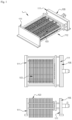
- Inspection device 1 is shown on the Figure 1 and the Figure 2 and includes a fixed support element 101.
- the support member 101 may be installed so as to be perpendicular to a frame intended to be installed on a support, and the frame may comprise a chassis 112 resting on the ground and a pair of support frames 111 provided on either side of the chassis 112 to face each other.
- the inspection apparatus 1 also comprises a movable member 102 installed to face the support member 101 and which is movable relative to the support member 101 along a main axis X in a first direction towards the support member 101 and a second direction opposite the first direction, each direction being along the main axis X.
- the first direction is defined as the direction in which the movable element 102 moves towards the support element 101 and the second direction is defined as the direction in which the movable element 102 moves away from the support element 101.
- the inspection apparatus also comprises pressure elements 103 installed between the support element 101 and the movable element 102 and freely movable along the main axis X. Two adjacent pressure elements 103 define a space 120 intended to receive only one secondary cell 110.
- the space 120 is intended to receive a single secondary cell 110. By receiving only one secondary cell, it is possible to carry out precise measurements on the cell 110.
- the pressure elements 103 may in particular be pressure panels which can be installed in parallel between the support element 101 and the movable element 102.
- the guide element 104 makes it possible to obtain substantially parallel plates, making it possible to obtain usable pressure measurements.
- the pressure measuring unit comprises a pressure sensor 106 interposed between a fixed element fixed to face the support element 101 and the support frame provided on one side of the chassis 112, and the pressure sensor 106 can be configured to measure a pressure when the pressure elements 103 pressurize the at least one secondary cell 110 when the drive unit 105 is in its first operating state.
- the pressure measuring unit comprises a pressure sensor comprised between two adjacent pressure elements among the pressure elements 103, and the pressure sensor 106 may comprise a load cell, a strain gauge, a force-sensitive resistor, or a combination of all of the aforementioned pressure sensors.
- the inspection apparatus 1 may further comprise an elastic support unit configured to elastically support the support member 101 to be returned to the pressure member side, wherein the elastic support unit may comprise a fixed member fixed to face the support member 101 and a compression spring 107 introduced into the guide element 104 so as to be positioned between the fixed element and the support element 101.
- the elastic support unit may comprise a fixed member fixed to face the support member 101 and a compression spring 107 introduced into the guide element 104 so as to be positioned between the fixed element and the support element 101.
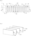
- each pressure element of the pressure elements 103 comprises a thermal plate 109 as can be seen in the Figure 3
- the thermal plate is configured to maintain a reasonably constant temperature between the pressure elements 103.
- the thermal plate is capable of maintaining a constant temperature between the pressure elements
- Thermal plates advantageously allow for reliable and high-quality current measurements. Indeed, the temperature of the surrounding environment does not affect current measurements. This eliminates the need for a current measurement correction step, as this correction step is usually performed by calculations taking into account a temperature value.
- Thermal plates are a metal plate in which a network of thermoregulatory elements extends. These thermoregulatory elements can be electrical or heat transfer fluid.
- each thermal plate 109 may be at least equal to the dimensions of the secondary cell or greater.
- the thermal plates 109 may be coupled to a temperature controller which controls a temperature value between two adjacent pressure elements 103.
- the temperature controller can set a temperature value with an accuracy of less than or equal to 0.1°C.
- the thermal plates 109 have an operating temperature range of 5°C to 120°C.
- the user can choose the reasonably constant temperature value within a temperature range of 5°C to 120°C, with an accuracy of plus or minus 0.1°C.
- An operating temperature within this temperature range allows for reliable current measurements while ensuring the physical and chemical integrity of the cells.
- this operating temperature range is adapted to the operating conditions of the inspection device 1.
- the pressure members 103 may each include a pressure pad attached to one or both sides of each pressure member 103 to effectively pressurize the at least one secondary cell 110, and the pressure pad may include a silicone pad and an insulating paper.
- the silicone pad is intended to prevent damage to the cell and the insulating paper is intended to prevent short circuits.
- the inspection apparatus 1 further comprises a current control unit configured to apply a voltage to the at least one secondary cell 110 and to measure a corresponding current through the at least one secondary cell 110.
- the current control unit carries out a control of the current of the at least one secondary cell 110 under pressure, which makes it possible to measure the current flowing through the at least one secondary cell 110.
- the current control unit applies a predetermined voltage to the at least one secondary cell 110, and measures the current of the at least one secondary cell 110.
- the inspection apparatus 1 may further comprise an electrode module connected to each of the electrode terminals of the at least one secondary cell 110 to thereby apply or receive current.
- the inspection apparatus 1 may further comprise a controller which is connected to the drive unit 105, the electrode module and the current control unit, respectively, to control the pressurizing and releasing operations of the drive unit 105, and to determine whether or not there is a defect in the at least one secondary cell 110 by comparing the measured current value given by the current control unit and a reference current value.
- a controller which is connected to the drive unit 105, the electrode module and the current control unit, respectively, to control the pressurizing and releasing operations of the drive unit 105, and to determine whether or not there is a defect in the at least one secondary cell 110 by comparing the measured current value given by the current control unit and a reference current value.
- the controller can determine whether there is a fault by comparing an average value of the current values measured by the current control unit with the reference value over a predetermined period of time which may depend on the parameters controlled by the user of the inspection device.
- the predetermined time period can be from 1 to 30 seconds.
- the reference current value can be determined from an experiment, for example by referring to a calibration curve or an abacus which shows whether the at least one secondary cell 110 is defective or not depending on the measured current value.
- the inspection apparatus 1 can enable the inspection of many secondary cells 110 simultaneously.
- the inspection apparatus 1 is intended to pressurize the at least one secondary cell 110 to enable or enhance physical contact between the first electrode 201 and the second electrode 202 through the contaminant 2 to induce an electric current that flows through the contaminant 2 between the first electrode 201 and the second electrode 202.
- the pressure applied to the at least one secondary cell 110 improves the detection of a potential contaminant 2 inside the at least one secondary cell 110; the current flowing through the contaminant 2 is therefore easier to detect.
- the first electrode 201 may be a cathode and the second electrode 202 may be an anode or vice versa.
- the movable element 102 installed to face the support element 101, moves in the first direction and in the second direction along the main axis X by the drive unit 105 to pressurize and depressurize the pressure elements 103.
- the movable element 102 moves in the first direction along the main axis X in order to pressurize the at least one secondary cell 110.
- a predetermined potential is applied to the cell and the current in the at least one secondary cell 110 is then measured and the movable element 102 moves in the second direction along the main axis X after the current measurement in order to release the at least one secondary cell 110.
- the movable element 102 is movable in translation in the first direction and the second direction, between a first position and a second position.
- the first position corresponds to the first state in which the cells are pressed by the drive unit 105
- the second position corresponds to the second state in which the cells are released by the drive unit 105.
- the pressure elements 103 pressurize the body portion of the at least one secondary cell 110.
- the body portion refers to the body portion of the at least one secondary cell 110, except for the electrode terminal of the at least one secondary cell 110.
- the pressure measuring unit can be interposed between the fixed element and the support frame to measure the pressure.
- the electrode may be detached or the appearance of the at least one secondary cell 110 may be damaged.
- the first electrode 201 and the second electrode 202 may not be physically in contact with each other through the contaminant 2, so that an internal short circuit may not be triggered, which decreases the reliability of fault detection.
- the pressure sensor 106 it is possible to verify whether an appropriate level of pressure is applied.
- a voltage is then applied by the current control unit to perform current control of the at least one secondary cell 110 under pressure.
- the energy source included in the current control unit applies a voltage across the electrode module to achieve a predetermined voltage value, and the current measurement unit measures the value of the current flowing through the at least one secondary cell 110.
- the current control unit and the electrode module may be electrically connected by a cable, or any other means of electrical connection.
- the electrode module electrically connects the current control unit to the at least one secondary cell 110.
- the electrode module can be attached to the inspection apparatus 1.
- the electrode module is connected to each of the electrode terminals of the at least one secondary cell 110 and applies the current applied by the current control unit to the at least one secondary cell 110, or transfers the current from the at least one secondary cell 110 to the current control unit.
- the thermal plates 109 act to maintain a reasonably constant temperature between the pressure elements 103. This allows the current value to be measured more accurately and sorting errors to be avoided.
- the controller which is connected to the drive unit 105, the electrode module and the current control unit, compares the current value measured by the current control unit and the reference current value in order to determine whether or not there is a defect. Furthermore, the controller can compare the current value of the at least one secondary cell 110 measured by the current control unit with a predetermined reference value of a good product and determines whether the value is acceptable according to the predetermined criteria. The result of the determination can be displayed by a display unit not shown.
- the controller therefore determines whether the at least one secondary cell 110 is good or not depending on whether the measured value based on the measured electricity quantity or the insulation degree corresponds to a predetermined standard and can enable the display unit or a data output device to display the result of the determination for at least one secondary cell 110.
- These values may vary based on feedback and data collection, after production and inspection of a certain number of secondary cells.
- the invention also relates to an inspection method for inspecting at least one secondary cell 110.
- the inspection method comprises a step of providing an inspection apparatus 1 as described previously and a step of providing the at least one secondary cell 110 to be inspected.
- a coil or stack can be created by assembling many first electrodes, many second electrodes, many separators, and other additional layers.
- the pressure sensor is used to check whether the applied pressure value is appropriate or not.
- the inspection method described makes it possible to maintain a reasonably constant temperature inside the inspection apparatus 1 thanks to the use of thermal plates 109 included in the pressure elements 103.
- the measured current flowing through the secondary cell is temperature dependent and will therefore be measured more accurately using the inspection method described.
- the described inspection method allows for more precise sorting of the at least one secondary cell 110 inspected.
- the inspection method can be applied during a manufacturing process of the at least one secondary cell 110 after an electrolyte impregnation phase, and before a first charge of the at least one secondary cell 110.
- the inspection method can be applied after the cell has been formed.
- the method and inspection apparatus described above have industrial application in the field of secondary cell manufacturing.
Landscapes
- Engineering & Computer Science (AREA)
- Manufacturing & Machinery (AREA)
- Chemical & Material Sciences (AREA)
- Chemical Kinetics & Catalysis (AREA)
- Electrochemistry (AREA)
- General Chemical & Material Sciences (AREA)
- Physics & Mathematics (AREA)
- General Physics & Mathematics (AREA)
- Secondary Cells (AREA)
- Investigating Or Analyzing Materials By The Use Of Electric Means (AREA)
- Fuel Cell (AREA)
- Investigating Or Analysing Materials By Optical Means (AREA)
Claims (13)
- Prüfvorrichtung (1) zum Prüfen mindestens einer Sekundärzelle (110), die Prüfvorrichtung (1) umfassend:- ein ortsfestes Trägerelement (101);- ein bewegliches Element (102), das so installiert ist, dass es dem Trägerelement (101) gegenüberliegt und relativ zu dem Trägerelement (101) entlang einer Hauptachse (X) in einer ersten Richtung zum Trägerelement (101) hin und einer zur ersten Richtung entgegengesetzten zweiten Richtung beweglich ist, wobei jede Richtung entlang der Hauptachse (X) verläuft;- Druckelemente (103), die zwischen dem Trägerelement (101) und dem beweglichen Element (102) installiert sind, wobei die Druckelemente (103) entlang der Hauptachse (X) frei beweglich sind und zwei benachbarte Druckelemente (103) einen Raum (120) definieren, der zur Aufnahme einer Sekundärzelle (110) bestimmt ist;
und- eine Antriebseinheit (105), die konfiguriert ist für den Betrieb:in einem ersten Zustand, in dem die Antriebseinheit (105) die mindestens eine Sekundärzelle (110), die sich zwischen den Druckelementen (103) befindet, beidseitig mit Druck beaufschlagt, undin einem zweiten Zustand, in dem die Antriebseinheit (105) die mindestens eine Sekundärzelle (110) freigibt,- eine Druckmesseinheit, die dazu konfiguriert ist, den von der Antriebseinheit (105) ausgeübten Druck zu messen;- eine Stromsteuereinheit, die dazu konfiguriert ist, eine Spannung an die mindestens eine Sekundärzelle (110) anzulegen und einen entsprechenden Strom durch die mindestens eine Sekundärzelle (110) zu messen;
wobei:
jedes Druckelement von den Druckelementen (103) eine Thermoplatte (109) umfasst, die eine Metallplatine mit einem Netzwerk aus Wärmeregelungselementen umfasst, wobei die Thermoplatte (109) dazu geeignet ist, eine konstante Temperatur zwischen den Druckelementen (103) in einem Temperaturbereich zwischen 5 °C und 120 °C aufrechtzuerhalten. - Prüfvorrichtung (1) nach Anspruch 1, ferner umfassend:- ein Führungselement (104), das dazu konfiguriert ist, jedes Druckelement (103) so zu führen, dass es sich entlang der Hauptachse (X) in der ersten Richtung und in der zweiten Richtung derart frei bewegen kann, dass der Raum (120) angepasst wird, der zwei benachbarte Druckelemente (103) voneinander trennt.
- Prüfvorrichtung (1) nach einem der Ansprüche 1 oder 2, wobei die Thermoplatten (109) mit einem Temperaturregler gekoppelt sind, der einen Temperaturwert zwischen zwei benachbarten Druckelementen regelt.
- Prüfvorrichtung (1) nach einem der Ansprüche 1 bis 3, wobei die Stromsteuereinheit umfasst:- eine Energiequelle zum Anlegen einer Spannung zum Erreichen eines vorgegebenen Spannungswerts relativ zu der mindestens einen durch die Druckelemente (103) mit Druck beaufschlagten Sekundärzelle (110); und- eine Strommesseinheit zum Messen eines durch die mindestens eine Sekundärzelle (110) fließenden Stromwerts.
- Prüfvorrichtung (1) nach einem der Ansprüche 1 bis 4, die ferner ein Elektrodenmodul umfasst, das mit jedem der Elektrodenanschlüsse der mindestens einen Sekundärzelle (110) verbunden ist, um somit Strom anzulegen oder zu empfangen.
- Prüfvorrichtung (1) nach den Ansprüchen 4 und 5, die ferner eine Steuerung umfasst, die mit der Antriebseinheit (105), dem Elektrodenmodul bzw. der Stromsteuereinheit verbunden ist, um die Druckbeaufschlagungs- und Entlastungsvorgänge der Antriebseinheit (105) zu steuern und um durch Vergleichen des von der Stromsteuereinheit ausgegebenen gemessenen Stromwerts mit einem Referenzstromwert zu bestimmen, ob in der mindestens einen Sekundärzelle (110) ein Defekt vorliegt oder nicht.
- Prüfvorrichtung (1) nach einem der Ansprüche 1 bis 6, die einen Rahmen umfasst, der dazu bestimmt ist, an einen Träger montiert zu werden, wobei das Trägerelement (101) so installiert ist, dass es senkrecht zum Rahmen steht,wobei der Rahmen ein auf dem Boden ruhendes Chassis (112) und ein Paar Stützrahmen (111) umfasst, die auf beiden Seiten des Chassis (112) einander zugewandt vorgesehen sind,und wobei:die Druckmesseinheit einen Drucksensor (106) umfasst, der zwischen einem ortsfesten Element, das dem Trägerelement (101) zugewandt befestigt ist, und dem Trägerrahmen, der auf einer Seite des Chassis (112) vorgesehen ist, angeordnet ist,wobei der Drucksensor (106) dazu konfiguriert ist, einen Druck zu messen, wenn die Druckelemente (103) die mindestens eine Sekundärzelle (110) mit Druck beaufschlagen, wenn sich die Antriebseinheit (105) in ihrem ersten Betriebszustand befindet.
- Prüfvorrichtung (1) nach einem der Ansprüche 1 bis 7, wobei die Druckmesseinheit einen Drucksensor umfasst, der zwischen zwei innerhalb der Druckelemente benachbarten Druckelementen angeordnet ist.
- Prüfvorrichtung (1) nach einem der Ansprüche 1 bis 8, wobei der Raum (120) zur Aufnahme einer einzelnen Sekundärzelle (110) bestimmt ist.
- Prüfvorrichtung (1) nach einem der Ansprüche 1 bis 9, wobei das bewegliche Element (102) in der ersten Richtung und der zweiten Richtung translatorisch zwischen einer ersten Position, die dem ersten Zustand entspricht, und einer zweiten Position, die dem zweiten Zustand entspricht, beweglich ist.
- Prüfverfahren zum Prüfen mindestens einer Sekundärzelle (110), das Prüfverfahren die folgenden Schritte umfassend:- Bereitstellen einer Prüfvorrichtung (1) nach einem der Ansprüche 1 bis 10;- Bereitstellen mindestens einer zu prüfenden Sekundärzelle (110);- Einsetzen der mindestens einen Sekundärzelle (110) in die Prüfvorrichtung (1), sodass die mindestens eine Sekundärzelle (110) zwischen zwei benachbarten Druckelementen (103) eingesetzt wird;- Druckbeaufschlagen und Freigeben der mindestens einen Sekundärzelle (110) zwischen den Druckelementen (103) auf beiden Seiten durch Bewegen des beweglichen Elements (102) relativ zum Trägerelement (101) entlang einer Hauptachse (X) in einer ersten Richtung und einer zweiten Richtung, die entlang der Hauptachse (X) einander entgegengesetzt sind;- Aufrechterhalten einer konstanten Temperatur zwischen den Druckelementen (103) durch Verwendung der in den Druckelementen (103) enthaltenen Thermoplatten (109);- Messen des auf die mindestens eine Sekundärzelle (110) ausgeübten Drucks mittels der Druckmesseinheit, um zu bestimmen, ob der ausgeübte Druck innerhalb eines vordefinierten Druckbereichs liegt;- Anlegen einer Spannung an die mindestens eine Sekundärzelle (110) und Messen eines entsprechenden Stroms durch die mindestens eine Sekundärzelle (110).
- Prüfverfahren nach Anspruch 11, ferner die folgenden Schritte umfassend:- Vergleichen des gemessenen Stromwerts mit einem Referenzstromwert;- Einsortieren der mindestens einen Sekundärzelle (110) als funktionsfähig oder defekt basierend auf dem Vergleich zwischen dem gemessenen Stromwert und dem Referenzstromwert, so dass:wenn der gemessene Stromwert den Referenzstromwert überschreitet, die mindestens eine Sekundärzelle (110) als defekt betrachtet wird,wenn der gemessene Stromwert kleiner als der Referenzstromwert ist, die mindestens eine Sekundärzelle (110) als funktionsfähig betrachtet wird.
- Prüfverfahren nach den Ansprüchen 11 und 12, wobei der Schritt des Bereitstellens der mindestens einen Sekundärzelle (110) die folgenden Teilschritte umfasst:- Zusammenbauen einer ersten Elektrode (201) und einer zweiten Elektrode (202) und eines zwischen der ersten Elektrode (201) und der zweiten Elektrode (202) angeordneten Separators (203), um eine Spule oder einen Stapel zu erzeugen;- Platzieren der Spule oder des Stapels in einem Gehäuse oder einem flexiblen Beutel;- Füllen des Gehäuses oder des Beutels mit einem Elektrolyten;- hermetisches Versiegeln des Gehäuses oder des Beutels, sodass mindestens eine Sekundärzelle (110) erhalten wird;- Aufladen der mindestens einen Sekundärzelle (110) auf einen vorgegebenen Ladezustand, um eine Festelektrolyt-Grenzfläche auf der Oberfläche der ersten Elektrode (201) zu bilden, bevor die mindestens eine Sekundärzelle (110) in die Prüfvorrichtung eingesetzt wird.
Applications Claiming Priority (2)
| Application Number | Priority Date | Filing Date | Title |
|---|---|---|---|
| FR2207369A FR3124271B1 (fr) | 2022-07-19 | 2022-07-19 | Appareil et procédé d’inspection d’une cellule secondaire |
| PCT/FR2023/051109 WO2024018150A1 (fr) | 2022-07-19 | 2023-07-18 | Appareil et procédé d'inspection d'une cellule secondaire |
Publications (3)
| Publication Number | Publication Date |
|---|---|
| EP4393025A1 EP4393025A1 (de) | 2024-07-03 |
| EP4393025C0 EP4393025C0 (de) | 2025-05-14 |
| EP4393025B1 true EP4393025B1 (de) | 2025-05-14 |
Family
ID=83438648
Family Applications (1)
| Application Number | Title | Priority Date | Filing Date |
|---|---|---|---|
| EP23749130.3A Active EP4393025B1 (de) | 2022-07-19 | 2023-07-18 | Vorrichtung und verfahren zur inspektion einer sekundärzelle |
Country Status (9)
| Country | Link |
|---|---|
| US (1) | US20260009863A1 (de) |
| EP (1) | EP4393025B1 (de) |
| KR (1) | KR20250026879A (de) |
| CN (1) | CN119744468A (de) |
| ES (1) | ES3035433T3 (de) |
| FR (1) | FR3124271B1 (de) |
| HU (1) | HUE072053T2 (de) |
| PL (1) | PL4393025T3 (de) |
| WO (1) | WO2024018150A1 (de) |
Family Cites Families (19)
| Publication number | Priority date | Publication date | Assignee | Title |
|---|---|---|---|---|
| JP3911038B2 (ja) * | 1995-08-31 | 2007-05-09 | ソニー株式会社 | 2次電池の残存容量検出方法 |
| CA2414982A1 (en) * | 2001-12-21 | 2003-06-21 | Wilson Greatbatch Technologies, Inc. | Grading cells for a battery pack |
| JP3820184B2 (ja) * | 2002-05-30 | 2006-09-13 | 松下電器産業株式会社 | 二次電池の交換方法 |
| US9172068B2 (en) * | 2009-10-22 | 2015-10-27 | Samsung Sdi Co., Ltd. | Battery pack |
| KR101293635B1 (ko) * | 2010-12-29 | 2013-08-05 | 주식회사 엘지화학 | 이차전지 셀의 퇴화 정도를 반영한 배터리 팩의 관리 장치와 방법 및 이를 구비한 배터리 팩 |
| JP5798067B2 (ja) * | 2012-03-13 | 2015-10-21 | プライムアースEvエナジー株式会社 | 二次電池の状態推定装置 |
| WO2013145917A1 (ja) * | 2012-03-27 | 2013-10-03 | ソニー株式会社 | 電池ユニット、電池モジュール、蓄電システム、電子機器、電力システムおよび電動車両 |
| KR102064459B1 (ko) | 2017-01-05 | 2020-01-09 | 주식회사 엘지화학 | 이차 전지의 저전압 불량 검사 방법 및 장치 |
| US10749225B2 (en) * | 2017-03-14 | 2020-08-18 | Ford Global Technologies, Llc | Thermal management assembly for traction battery cells |
| JP6885236B2 (ja) * | 2017-07-10 | 2021-06-09 | トヨタ自動車株式会社 | 蓄電デバイスの短絡検査方法及び蓄電デバイスの製造方法 |
| EP3460893B1 (de) * | 2017-09-21 | 2020-01-08 | Helmholtz-Zentrum Geesthacht Zentrum für Material- und Küstenforschung GmbH | Vorrichtung zum einspannen und temperieren von flachen proben für die röntgendiffraktometrie |
| KR102106448B1 (ko) * | 2017-12-11 | 2020-05-04 | 삼성에스디아이 주식회사 | 배터리 팩 |
| KR102577275B1 (ko) * | 2017-12-22 | 2023-09-12 | 삼성전자주식회사 | 2차 전지의 실시간 열 거동 분석용 모듈 및 그 동작방법 |
| EP3683589B1 (de) * | 2018-06-11 | 2023-03-29 | LG Energy Solution, Ltd. | Vorrichtung zur gleichzeitigen inspektion mehrerer sekundärbatteriezellen-pouches |
| KR102509603B1 (ko) * | 2019-09-18 | 2023-03-10 | 주식회사 엘지에너지솔루션 | 저전압 불량 파우치형 이차전지 셀을 검출하기 위한 가압 단락 검사장치 |
| KR102772770B1 (ko) * | 2019-10-14 | 2025-02-24 | 주식회사 엘지에너지솔루션 | 전지 모듈 및 이를 포함한 전지 팩 |
| DE102020005411A1 (de) * | 2020-09-04 | 2020-11-19 | Daimler Ag | Verfahren zum Testen mindestens einer elektrochemischen Einzelzelle oder mehrerer elektrochemischer Einzelzellen |
| KR102461833B1 (ko) * | 2020-12-09 | 2022-11-01 | 에스케이온 주식회사 | 배터리 모듈 |
| KR20240128476A (ko) * | 2023-02-17 | 2024-08-26 | 에스케이온 주식회사 | 배터리모듈 및 배터리모듈의 제조방법 |
-
2022
- 2022-07-19 FR FR2207369A patent/FR3124271B1/fr active Active
-
2023
- 2023-07-18 CN CN202380054997.6A patent/CN119744468A/zh active Pending
- 2023-07-18 HU HUE23749130A patent/HUE072053T2/hu unknown
- 2023-07-18 US US18/996,279 patent/US20260009863A1/en active Pending
- 2023-07-18 ES ES23749130T patent/ES3035433T3/es active Active
- 2023-07-18 KR KR1020257004538A patent/KR20250026879A/ko not_active Ceased
- 2023-07-18 WO PCT/FR2023/051109 patent/WO2024018150A1/fr not_active Ceased
- 2023-07-18 PL PL23749130.3T patent/PL4393025T3/pl unknown
- 2023-07-18 EP EP23749130.3A patent/EP4393025B1/de active Active
Also Published As
| Publication number | Publication date |
|---|---|
| HUE072053T2 (hu) | 2025-10-28 |
| PL4393025T3 (pl) | 2025-06-30 |
| EP4393025C0 (de) | 2025-05-14 |
| CN119744468A (zh) | 2025-04-01 |
| KR20250026879A (ko) | 2025-02-25 |
| FR3124271B1 (fr) | 2024-08-09 |
| EP4393025A1 (de) | 2024-07-03 |
| FR3124271A1 (fr) | 2022-12-23 |
| US20260009863A1 (en) | 2026-01-08 |
| WO2024018150A1 (fr) | 2024-01-25 |
| ES3035433T3 (en) | 2025-09-03 |
Similar Documents
| Publication | Publication Date | Title |
|---|---|---|
| CN109244573B (zh) | 蓄电设备的短路检查方法和蓄电设备的制造方法 | |
| EP2233937B1 (de) | Verfahren zur Bestimmung des Gesundheitszustands einer Batterie | |
| FR2991510A1 (fr) | Cellule de batterie equipee d'un capteur en forme de film sensible a la pression | |
| EP3553544A1 (de) | Fehlerüberprüfungsvorrichtung für wiederaufladbare batterie und fehlerüberprüfungsverfahren | |
| CN104515954B (zh) | 二次电池的制造方法 | |
| CN112213650B (zh) | 蓄电设备的检查方法及制造方法 | |
| KR20210155518A (ko) | 전지 셀의 불량 판정 시스템 및 이를 이용한 전지 셀의 불량 판정 방법 | |
| EP2989677B1 (de) | Vorrichtung zur verwaltung eines akkumulators | |
| EP4393025B1 (de) | Vorrichtung und verfahren zur inspektion einer sekundärzelle | |
| WO2010055233A1 (fr) | Procédé de surveillance de la tension d'un élément générateur d'énergie électrique d'une batterie | |
| EP4393026B1 (de) | Vorrichtung und verfahren zur inspektion einer sekundärzelle | |
| FR3034260B1 (fr) | Procede de determination d'au moins un etat de securite d'un accumulateur electrochimique au lithium au moyen de jauge(s) de contrainte | |
| CN114977358B (zh) | 蓄电设备的设备电压调整方法 | |
| EP3943962B1 (de) | Vorrichtung und verfahren zur inspektion des defekts einer sekundärbatterie | |
| CN215004841U (zh) | 一种测量隔膜浸润性的装置 | |
| CN118533333A (zh) | 植入式免封装薄膜压力传感器、植入传感电芯、电池模组、电子设备及储能装置 | |
| JP2025095789A (ja) | 蓄電装置の製造方法 | |
| JPH10144360A (ja) | 電池パックの検査方法および検査器 | |
| KR101398477B1 (ko) | 충방전기의 충전 전압 정밀도 검출 장치 | |
| CN220960397U (zh) | 用于测量圆柱电池膨胀应力的装置 | |
| CN114966445A (zh) | 二次电池的内部电阻检查方法和二次电池的制造方法 | |
| FR3166705A1 (fr) | Système de mesure physique au cœur d’un accumulateur électrochimique et procédé associé | |
| EP4391142A2 (de) | Vorrichtung und verfahren zur erkennung einer verformung einer verpackung einer batteriezelle | |
| FR3102860A1 (fr) | Appareil asymétrique de diagnostic, de charge et/ou de décharge de batteries électriques et conducteurs pour ledit appareil | |
| WO2026047981A1 (ja) | 二次電池の検査方法 |
Legal Events
| Date | Code | Title | Description |
|---|---|---|---|
| STAA | Information on the status of an ep patent application or granted ep patent |
Free format text: STATUS: UNKNOWN |
|
| STAA | Information on the status of an ep patent application or granted ep patent |
Free format text: STATUS: THE INTERNATIONAL PUBLICATION HAS BEEN MADE |
|
| PUAI | Public reference made under article 153(3) epc to a published international application that has entered the european phase |
Free format text: ORIGINAL CODE: 0009012 |
|
| STAA | Information on the status of an ep patent application or granted ep patent |
Free format text: STATUS: REQUEST FOR EXAMINATION WAS MADE |
|
| 17P | Request for examination filed |
Effective date: 20240326 |
|
| AK | Designated contracting states |
Kind code of ref document: A1 Designated state(s): AL AT BE BG CH CY CZ DE DK EE ES FI FR GB GR HR HU IE IS IT LI LT LU LV MC ME MK MT NL NO PL PT RO RS SE SI SK SM TR |
|
| GRAP | Despatch of communication of intention to grant a patent |
Free format text: ORIGINAL CODE: EPIDOSNIGR1 |
|
| STAA | Information on the status of an ep patent application or granted ep patent |
Free format text: STATUS: GRANT OF PATENT IS INTENDED |
|
| INTG | Intention to grant announced |
Effective date: 20250107 |
|
| GRAS | Grant fee paid |
Free format text: ORIGINAL CODE: EPIDOSNIGR3 |
|
| GRAA | (expected) grant |
Free format text: ORIGINAL CODE: 0009210 |
|
| STAA | Information on the status of an ep patent application or granted ep patent |
Free format text: STATUS: THE PATENT HAS BEEN GRANTED |
|
| AK | Designated contracting states |
Kind code of ref document: B1 Designated state(s): AL AT BE BG CH CY CZ DE DK EE ES FI FR GB GR HR HU IE IS IT LI LT LU LV MC ME MK MT NL NO PL PT RO RS SE SI SK SM TR |
|
| DAV | Request for validation of the european patent (deleted) | ||
| DAX | Request for extension of the european patent (deleted) | ||
| REG | Reference to a national code |
Ref country code: GB Ref legal event code: FG4D Free format text: NOT ENGLISH |
|
| REG | Reference to a national code |
Ref country code: CH Ref legal event code: EP |
|
| REG | Reference to a national code |
Ref country code: IE Ref legal event code: FG4D Free format text: LANGUAGE OF EP DOCUMENT: FRENCH |
|
| REG | Reference to a national code |
Ref country code: DE Ref legal event code: R096 Ref document number: 602023003522 Country of ref document: DE |
|
| U01 | Request for unitary effect filed |
Effective date: 20250530 |
|
| U07 | Unitary effect registered |
Designated state(s): AT BE BG DE DK EE FI FR IT LT LU LV MT NL PT RO SE SI Effective date: 20250610 |
|
| REG | Reference to a national code |
Ref country code: ES Ref legal event code: FG2A Ref document number: 3035433 Country of ref document: ES Kind code of ref document: T3 Effective date: 20250903 |
|
| U20 | Renewal fee for the european patent with unitary effect paid |
Year of fee payment: 3 Effective date: 20250730 |
|
| REG | Reference to a national code |
Ref country code: SK Ref legal event code: T3 Ref document number: E 46734 Country of ref document: SK |
|
| PGFP | Annual fee paid to national office [announced via postgrant information from national office to epo] |
Ref country code: HU Payment date: 20250807 Year of fee payment: 3 |
|
| PGFP | Annual fee paid to national office [announced via postgrant information from national office to epo] |
Ref country code: ES Payment date: 20250819 Year of fee payment: 3 |
|
| PG25 | Lapsed in a contracting state [announced via postgrant information from national office to epo] |
Ref country code: GR Free format text: LAPSE BECAUSE OF FAILURE TO SUBMIT A TRANSLATION OF THE DESCRIPTION OR TO PAY THE FEE WITHIN THE PRESCRIBED TIME-LIMIT Effective date: 20250815 |
|
| PGFP | Annual fee paid to national office [announced via postgrant information from national office to epo] |
Ref country code: NO Payment date: 20250801 Year of fee payment: 3 |
|
| PGFP | Annual fee paid to national office [announced via postgrant information from national office to epo] |
Ref country code: TR Payment date: 20250807 Year of fee payment: 3 Ref country code: PL Payment date: 20250709 Year of fee payment: 3 |
|
| PG25 | Lapsed in a contracting state [announced via postgrant information from national office to epo] |
Ref country code: HR Free format text: LAPSE BECAUSE OF FAILURE TO SUBMIT A TRANSLATION OF THE DESCRIPTION OR TO PAY THE FEE WITHIN THE PRESCRIBED TIME-LIMIT Effective date: 20250514 |
|
| PG25 | Lapsed in a contracting state [announced via postgrant information from national office to epo] |
Ref country code: RS Free format text: LAPSE BECAUSE OF FAILURE TO SUBMIT A TRANSLATION OF THE DESCRIPTION OR TO PAY THE FEE WITHIN THE PRESCRIBED TIME-LIMIT Effective date: 20250814 |
|
| PGFP | Annual fee paid to national office [announced via postgrant information from national office to epo] |
Ref country code: CZ Payment date: 20250708 Year of fee payment: 3 |
|
| PGFP | Annual fee paid to national office [announced via postgrant information from national office to epo] |
Ref country code: SK Payment date: 20250624 Year of fee payment: 3 |
|
| PG25 | Lapsed in a contracting state [announced via postgrant information from national office to epo] |
Ref country code: IS Free format text: LAPSE BECAUSE OF FAILURE TO SUBMIT A TRANSLATION OF THE DESCRIPTION OR TO PAY THE FEE WITHIN THE PRESCRIBED TIME-LIMIT Effective date: 20250914 |
|
| REG | Reference to a national code |
Ref country code: HU Ref legal event code: AG4A Ref document number: E072053 Country of ref document: HU |
|
| PG25 | Lapsed in a contracting state [announced via postgrant information from national office to epo] |
Ref country code: SM Free format text: LAPSE BECAUSE OF FAILURE TO SUBMIT A TRANSLATION OF THE DESCRIPTION OR TO PAY THE FEE WITHIN THE PRESCRIBED TIME-LIMIT Effective date: 20250514 |
|
| PLBE | No opposition filed within time limit |
Free format text: ORIGINAL CODE: 0009261 |
|
| STAA | Information on the status of an ep patent application or granted ep patent |
Free format text: STATUS: NO OPPOSITION FILED WITHIN TIME LIMIT |
|
| REG | Reference to a national code |
Ref country code: CH Ref legal event code: L10 Free format text: ST27 STATUS EVENT CODE: U-0-0-L10-L00 (AS PROVIDED BY THE NATIONAL OFFICE) Effective date: 20260325 |
|
| 26N | No opposition filed |
Effective date: 20260217 |