EP3553544A1 - Fehlerüberprüfungsvorrichtung für wiederaufladbare batterie und fehlerüberprüfungsverfahren - Google Patents
Fehlerüberprüfungsvorrichtung für wiederaufladbare batterie und fehlerüberprüfungsverfahren Download PDFInfo
- Publication number
- EP3553544A1 EP3553544A1 EP18832786.0A EP18832786A EP3553544A1 EP 3553544 A1 EP3553544 A1 EP 3553544A1 EP 18832786 A EP18832786 A EP 18832786A EP 3553544 A1 EP3553544 A1 EP 3553544A1
- Authority
- EP
- European Patent Office
- Prior art keywords
- electrode assembly
- pressing
- protrusions
- secondary battery
- pouch
- Prior art date
- Legal status (The legal status is an assumption and is not a legal conclusion. Google has not performed a legal analysis and makes no representation as to the accuracy of the status listed.)
- Granted
Links
Images


Classifications
-
- G—PHYSICS
- G01—MEASURING; TESTING
- G01R—MEASURING ELECTRIC VARIABLES; MEASURING MAGNETIC VARIABLES
- G01R31/00—Arrangements for testing electric properties; Arrangements for locating electric faults; Arrangements for electrical testing characterised by what is being tested not provided for elsewhere
- G01R31/36—Arrangements for testing, measuring or monitoring the electrical condition of accumulators or electric batteries, e.g. capacity or state of charge [SoC]
- G01R31/392—Determining battery ageing or deterioration, e.g. state of health
-
- G—PHYSICS
- G01—MEASURING; TESTING
- G01R—MEASURING ELECTRIC VARIABLES; MEASURING MAGNETIC VARIABLES
- G01R31/00—Arrangements for testing electric properties; Arrangements for locating electric faults; Arrangements for electrical testing characterised by what is being tested not provided for elsewhere
- G01R31/36—Arrangements for testing, measuring or monitoring the electrical condition of accumulators or electric batteries, e.g. capacity or state of charge [SoC]
- G01R31/3644—Constructional arrangements
-
- G—PHYSICS
- G01—MEASURING; TESTING
- G01R—MEASURING ELECTRIC VARIABLES; MEASURING MAGNETIC VARIABLES
- G01R1/00—Details of instruments or arrangements of the types included in groups G01R5/00 - G01R13/00 and G01R31/00
- G01R1/02—General constructional details
- G01R1/06—Measuring leads; Measuring probes
- G01R1/067—Measuring probes
- G01R1/06794—Devices for sensing when probes are in contact, or in position to contact, with measured object
-
- G—PHYSICS
- G01—MEASURING; TESTING
- G01R—MEASURING ELECTRIC VARIABLES; MEASURING MAGNETIC VARIABLES
- G01R31/00—Arrangements for testing electric properties; Arrangements for locating electric faults; Arrangements for electrical testing characterised by what is being tested not provided for elsewhere
- G01R31/36—Arrangements for testing, measuring or monitoring the electrical condition of accumulators or electric batteries, e.g. capacity or state of charge [SoC]
- G01R31/389—Measuring internal impedance, internal conductance or related variables
-
- H—ELECTRICITY
- H01—ELECTRIC ELEMENTS
- H01M—PROCESSES OR MEANS, e.g. BATTERIES, FOR THE DIRECT CONVERSION OF CHEMICAL ENERGY INTO ELECTRICAL ENERGY
- H01M10/00—Secondary cells; Manufacture thereof
- H01M10/42—Methods or arrangements for servicing or maintenance of secondary cells or secondary half-cells
- H01M10/4285—Testing apparatus
-
- H—ELECTRICITY
- H01—ELECTRIC ELEMENTS
- H01M—PROCESSES OR MEANS, e.g. BATTERIES, FOR THE DIRECT CONVERSION OF CHEMICAL ENERGY INTO ELECTRICAL ENERGY
- H01M50/00—Constructional details or processes of manufacture of the non-active parts of electrochemical cells other than fuel cells, e.g. hybrid cells
- H01M50/10—Primary casings; Jackets or wrappings
- H01M50/116—Primary casings; Jackets or wrappings characterised by the material
-
- G—PHYSICS
- G01—MEASURING; TESTING
- G01R—MEASURING ELECTRIC VARIABLES; MEASURING MAGNETIC VARIABLES
- G01R31/00—Arrangements for testing electric properties; Arrangements for locating electric faults; Arrangements for electrical testing characterised by what is being tested not provided for elsewhere
- G01R31/36—Arrangements for testing, measuring or monitoring the electrical condition of accumulators or electric batteries, e.g. capacity or state of charge [SoC]
- G01R31/385—Arrangements for measuring battery or accumulator variables
- G01R31/3865—Arrangements for measuring battery or accumulator variables related to manufacture, e.g. testing after manufacture
-
- Y—GENERAL TAGGING OF NEW TECHNOLOGICAL DEVELOPMENTS; GENERAL TAGGING OF CROSS-SECTIONAL TECHNOLOGIES SPANNING OVER SEVERAL SECTIONS OF THE IPC; TECHNICAL SUBJECTS COVERED BY FORMER USPC CROSS-REFERENCE ART COLLECTIONS [XRACs] AND DIGESTS
- Y02—TECHNOLOGIES OR APPLICATIONS FOR MITIGATION OR ADAPTATION AGAINST CLIMATE CHANGE
- Y02E—REDUCTION OF GREENHOUSE GAS [GHG] EMISSIONS, RELATED TO ENERGY GENERATION, TRANSMISSION OR DISTRIBUTION
- Y02E60/00—Enabling technologies; Technologies with a potential or indirect contribution to GHG emissions mitigation
- Y02E60/10—Energy storage using batteries
Definitions
- the present invention relates to an apparatus and method for inspecting defects of a secondary battery.
- Secondary batteries are rechargeable unlike primarily batteries, and also, the possibility of compact size and high capacity is high. Thus, recently, many studies on secondary batteries are being carried out. As technology development and demands for mobile devices increase, the demands for secondary batteries as energy sources are rapidly increasing.
- Secondary batteries are classified into coin type batteries, cylindrical type batteries, prismatic type batteries, and pouch type batteries according to a shape of a pouch.
- an electrode assembly mounted in a pouch is a chargeable and dischargeable power generating device having a structure in which an electrode and a separator are stacked.
- the electrode assembly may be approximately classified into a jelly-roll type electrode assembly in which a separator is interposed between a positive electrode and a negative electrode, each of which is provided as the form of a sheet coated with an active material, and then, the positive electrode, the separator, and the negative electrode are wound, a stacked type electrode assembly in which a plurality of positive and negative electrodes with a separator therebetween are sequentially stacked, and a stack/folding type electrode assembly in which stacked type unit cells are wound together with a separation film having a long length.
- a separator electrically insulates a positive electrode from a negative electrode to prevent internal short-circuit from occurring.
- the separator may be torn, damaged, or folded during a process of manufacturing an electrode or a secondary battery comprising the electrode assembly to locally cause contact between electrodes.
- low voltage failure, ignition, and explosion may occur due to the contact between the electrodes.
- One aspect of the present invention is to provide an apparatus and method for inspecting defects of a secondary battery, which are capable of inspecting existence and nonexistence of defects with respect to an electrode assembly of the secondary battery.
- another aspect of the present invention is to provide an apparatus and method for inspecting defects of a secondary battery, which are capable of inspecting existence and nonexistence of short circuit of an electrode due to damage of a separator of an electrode assembly.
- An apparatus for inspecting defects of a secondary battery comprises a pair of pressing jigs which press an outer surface of an electrode assembly or a pouch accommodating the electrode assembly in directions towards each other and on which a plurality of protrusions protrude from pressing surfaces of the pair of pressing jigs and a measurement unit measuring one or more of current, a voltage, and resistance of the electrode assembly when the electrode assembly is pressed by the plurality of protrusions of the pair of pressing jigs.
- a method for inspecting defects of a secondary battery comprises a pressing step of pressing an outer surface of an electrode assembly or a pouch accommodating the electrode assembly through a pair of pressing jigs on which a plurality of protrusions protrude from pressing surfaces in directions towards each other and a measurement step of measuring one or more of current, a voltage, and resistance of the electrode assembly through a measurement unit when the electrode assembly is pressed by the plurality of protrusions through the pressing step.
- the current, the voltage, or the resistance of the electrode assembly may be measured while pressing the electrode assembly through the pair of pressing jigs to inspect the existence and nonexistence of the defects of the electrode assembly.
- the plurality of protrusions may protrude from the pressing surfaces of the pair of pressing jigs.
- the current, the voltage, or the resistance of the electrode assembly may be measured while the plurality of protrusions press the outer surface of the electrode assembly to precisely detect the existence and nonexistence of the short circuit of the electrode due to the damage of the separator.
- the electrode assembly may be pressed through the plurality of protrusions to detect the internal short circuit at the local portion.
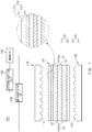
- FIG. 1 is a conceptual cross-sectional view of an apparatus for inspecting defects of a secondary battery according to an embodiment of the present invention.
- an apparatus 100 for inspecting defects of a secondary battery comprises a pair of pressing jigs 110 and 120 pressing an electrode assembly 10 or a pouch accommodating the electrode assembly 10 and a measurement unit 130 measuring one or more of current, a voltage, and resistance of the pressed electrode assembly 10.
- the apparatus 100 for inspecting defects of the secondary battery may further comprise a determination unit 140 determining whether the electrode assembly 10 is defective and a memory in which standard values with respect to the current, the voltage, and the resistance of the electrode assembly 10 are stored.
- FIG. 2 is a cross-sectional view illustrating an example of the pressing jig in the apparatus for inspecting defects of the secondary battery according to an embodiment of the present invention
- FIG. 3 is a cross-sectional view illustrating another example of the pressing jig in the apparatus for inspecting defects of the secondary battery according to an embodiment of the present invention
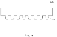
- FIG. 4 is a cross-sectional view illustrating further another example of the pressing jig in the apparatus for inspecting defects of the secondary battery according to an embodiment of the present invention.
- FIGS. 1 to 6 the apparatus for inspecting defects of the secondary battery according to an embodiment of the present invention will be described in more detail with reference to FIGS. 1 to 6 .
- the electrode assembly 10 that is tested through the apparatus for inspecting defects of the secondary battery may be a chargeable and dischargeable power generation element and, for example, have a structure in which an electrode 13 and a separator 14 are combined with each other and stacked.
- the electrode 13 may comprise a positive electrode 11 and a negative electrode 12.
- the electrode assembly 10 may have a structure in which the positive electrode 11/the separator 14/the negative electrode 12 are alternately stacked.
- the separator 14 may be disposed between the positive electrode 11 and the negative electrode 12 and disposed outside the positive electrode 11 and outside the negative electrode 12.
- the separator 14 may be disposed to surround the entire electrode assembly 10 in which the positive electrode 11/the separator 14/the negative electrode 12 are stacked.
- the separator 14 is made of an insulation material to electrically insulate the positive electrode 11 from the negative electrode 12.
- the separator 14 may be made of, for example, a polyolefin-based resin film such as polyethylene or polypropylene having micropores.
- the secondary battery may further comprise an electrode lead 20 electrically connected to the electrode 13.
- the electrode lead 20 may comprise a positive electrode lead 21 connected to the positive electrode 11 and a negative electrode lead 22 connected to the negative electrode 12.
- the electrode lead 20 may be connected to the electrode 13 by being connected to an electrode tab 30, which is attached to the electrode 13 to protrude.
- the positive electrode lead 21 may be connected to a positive electrode tab 31, and the negative electrode lead 22 may be connected to a negative electrode tab 32.
- the pressing jigs 110 and 120 may be provided in a pair to press an outer surface of the electrode assembly 10 or the pouch accommodating the electrode assembly 10 in directions corresponding to each other. That is, the pair of pressing jigs 110 and 120 may move in direction facing each other to press both surfaces of the electrode assembly 10 or the pouch.
- a plurality of protrusions 111 and 121 may protrude from pressing surfaces of the pressing jigs 110 and 120.
- the plurality of protrusions 111 and 121 may be disposed on facing surfaces of the pair of pressing jigs 110 and 120 to extend and protrude in directions facing each other.
- Each of the protrusions 111 and 121 may be made of a metal material or a plastic material.
- each of the protrusions 111 and 121 may be made of, for example, a plastic foam material.
- each of the protrusions 111 and 121 of the pressing jig 110 may have a rounded end.
- each of the protrusions 111 and 121 may have a hemispherical shape.
- a protrusion 111' of a pressing jig 110' may have a rectangular pillar shape having a width greater than a protruding length thereof.
- the protrusion 111' may have a width that gradually decreases toward a distal end thereof.
- a protrusion 111" of a pressing jig 110" may have a rectangular pillar shape having a protruding length greater than a width thereof.
- the protrusion 111" may have a tapered end that gradually decreases in width toward a distal end thereof.
- the determination unit 140 may receive values measured through the measurement unit 130 to determine whether the electrode assembly 10 is defective.
- the memory 150 may store the standard values with respect to the current, the voltage, and the resistance of the electrode assembly 10.
- the determination unit 140 may compare the standard values with respect to the current, the voltage, and the resistance of the electrode assembly 10, which are stored in the memory 150, to the measured values of the current, the voltage, and the resistance of the electrode assembly 10, which are measured through the measurement unit 130 to determine whether the electrode assembly 10 is defective.
- the determination unit 140 may determine that the electrode assembly 10 is defective.
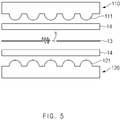
- FIG. 5 is a cross-sectional view illustrating a state before being pressed through the pressing jig in the apparatus for inspecting defects of the secondary battery according to an embodiment of the present invention
- FIG. 6 is a cross-sectional view illustrating a state being pressed through the pressing jig in the apparatus for inspecting defects of the secondary battery according to an embodiment of the present invention.
- the measurement unit 130 may detect that the measured values are out of the range of the standard values due to the short circuit of the electrode by measuring the current, the voltage, and the resistance of the electrode assembly 10.
- internal short circuit at a local portion which is not detected when the entire outer surface of the electrode assembly or the pouch is pressed, may be precisely detected by pressing the electrode assembly or the pouch by using the plurality of protrusions 111 and 121.
- FIG. 7 is a conceptual cross-sectional view of an apparatus for inspecting defects of a secondary battery according to another embodiment of the present invention.
- an apparatus 200 for inspecting defects of a secondary battery according to another embodiment of the present invention is different from the apparatus 100 for inspecting defects of the secondary battery according to the foregoing embodiment of the present invention in that flexible layers 230 and 240 are further provided on pressing jigs 210 and 220.
- this embodiment which are duplicated with those according to the forgoing embodiment, will be briefly described, and also, differences therebetween will be mainly described.
- the pair of pressing jigs 210 and 220 are provided with the flexible layers 230 and 240.
- the flexible layers 230 and 240 may be disposed on surfaces facing each other of the pair of pressing jigs 210 and 220.
- the flexible layers 230 and 240 may comprise outer surfaces of protrusions 211 and 221 disposed on pressing surfaces of the pressing jigs 210 and 220.
- each of the flexible layers 230 and 240 may be made of a material having flexibility and an insulation material.
- each of the flexible layers 230 and 240 may be made of, for example, a polymer material.
- the flexible layers 230 and 240 may be disposed on the outer surfaces of the protrusions 211 and 221 to prevent the electrode assembly 10 from being damaged by the protrusions 211 and 221 of the pressing jigs 210 and 220.
- the flexible layers 230 and 240 may be disposed on the pressing surfaces of the pressing jigs 210 and 220 to prevent safety from being deteriorated due to the damage of the pouch 40 and the electrode assembly 10.
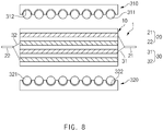
- FIG. 8 is a conceptual cross-sectional view of an apparatus for inspecting defects of a secondary battery according to further another embodiment of the present invention
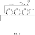
- FIG. 9 is a cross-sectional view of a pressing jig in the apparatus for inspecting defects of the secondary battery according to further another embodiment of the present invention
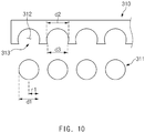
- FIG. 10 is an exploded cross-sectional view of the pressing jig in the apparatus for inspecting defects of the secondary battery according to further another embodiment of the present invention.
- an apparatus 300 for inspecting defects of a secondary battery according to further another embodiment of the present invention is different from the apparatus 100 for inspecting defects of the secondary battery according to the foregoing embodiment and the apparatus 200 for inspecting defects of the secondary battery according to another embodiment in that protrusions 311 and 321 are rotatably provided on pressing jigs 310 and 320.
- protrusions 311 and 321 are rotatably provided on pressing jigs 310 and 320.
- each of the protrusions 311 and 321 of the pair of pressing jigs 310 and 320 may have a spherical shape, and mounting grooves 312 and 322 in which the protrusions 311 and 321 are mounted may be formed in the pressing jigs 310 and 320.
- the mounting grooves 312 and 322 may be formed in pressing sides of the pressing jigs 310 and 320.
- the mounting grooves 312 and 322 may be formed so that one side of each of the protrusions 311 and 321 protrude to the outside of each of the mounting grooves 312 and 322.
- each of the mounting grooves 312 and 322 may have a depth greater than a radius r1 and less than a diameter d1 of each of the protrusions 311 and 321 so that a portion of each of the protrusions 311 and 321 protrudes to the outside of each of the mounting grooves 312 and 322.
- an inlet hole 313 through which a portion of each of the protrusions 311 and 321 protrudes may be formed in an inlet of each of the mounting grooves 312 and 322.
- the inlet hole 313 of each of the mounting grooves 312 and 322 may have a diameter d3 less than the diameter d1 of each of the protrusions 311 and 321 to prevent the protrusions 311 and 321 from being separated from the mounting grooves 312 and 322.
- each of the mounting grooves 312 and 322 may have a diameter d2 equal to or greater than the diameter d1 of each of the protrusions 311 and 321.
- each of the mounting grooves 312 and 322 may have a shape corresponding to each of the protrusions 311 and 321.
- each of the protrusions 311 and 321 may have a spherical shape, and each of the mounting grooves 312 and 322 may have a shape corresponding to each of the protrusions 311 and 321.
- the protrusions 311 and 321 may rotate to allow the pressing jigs 310 and 320 to move.
- the portions to be pressed may be prevented from being damaged by the protrusions 311 and 321. That is, the outer surface of the electrode assembly 10 or the pouch, which is pressed by the protrusions 311 and 321, may be prevented from being damaged.
- each of the protrusions 311 and 321 may have, for example, a diameter of 0.2 mm to 30 mm. Furthermore, each of the protrusions 311 and 321 may have, particularly, a diameter of 0.5 mm to 10 mm. Here, since the protrusion has the diameter of 10 mm or less, accurate measurement may be enabled. Also, since the protrusion has the diameter of 0.5 mm or more, the electrode assembly 10 or the pouch may be prevented from being damaged when being pressed. Here, if a pressing area pressed by the protrusion is narrow, pressing force applied per unit area may increase to damage the electrode assembly 10 or the pouch.
- FIG. 11 is a cross-sectional view of the apparatus for inspecting defects of the secondary battery, which is applied to a method for inspecting defects of the secondary battery according to an embodiment of the present invention.
- the method for inspecting defects of the secondary battery comprises a pressing step of pressing an electrode assembly 10 or a pouch accommodating the electrode assembly 10 through a pair of pressing jigs 110 and 120 of an apparatus 400 for inspecting defects and a measurement step of measuring one or more of current, a voltage, and resistance of the pressed electrode assembly 10.
- the method for inspecting defects of the secondary battery according to an embodiment of the present invention may further comprise a determination step of determining whether electrode assembly 10 is defective.
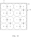
- FIG. 12 is a conceptual view illustrating a pressing method of the pressing step in the method for inspecting defects of the secondary battery according to an embodiment of the present invention.
- an outer surface of the electrode assembly 10 or the pouch accommodating the electrode assembly 10 are pressed in directions corresponding to each other through the pair of pressing jigs 110 and 120 on which a plurality of protrusions 111 and 121 protrude from pressing surfaces.
- the outer surface of the electrode assembly 10 or the pouch may be pressed at a pressure of 1 kg/cm 2 to 5,000 kg/cm 2 through the pair of pressing jigs 110 and 120.
- the outer surface of the electrode assembly 10 or the pouch may be pressed at a pressure of 10 kg/cm 2 to 1,000 kg/cm 2 through the pair of pressing jigs 110 and 120.
- pressing force that is required for causing short circuit may be secured to more facilitate the measurement. That is, when pressed at a pressure of 10 kg/cm 2 or more, the pressing force required for allowing a positive electrode 11 to contact a negative electrode 12 may reach a damaged portion S of a separator 14 to easily cause the short circuit. Thus, the damaged portion S of the separator 140 may be detected (see FIG. 6 ).
- the electrode assembly 10 or the pouch when the outer surface of the electrode assembly 10 or the pouch is pressed at a pressure of 1,000 kg/cm 2 or less, the electrode assembly 10 or the pouch may be prevented from being damaged or broken.
- each of the flexible films 460 and 470 may be made of a polymer material.
- the pair of pressing jigs 110 and 120 may repeatedly move upward and downward to press the electrode assembly 10 or the pouch.
- each of the pair of pressing jigs 110 and 120 move along a predetermined path to press the electrode assembly 10.
- a portion 1 of the outer surface of the electrode assembly 10 may be pressed through the upward and downward movement of the pair of pressing jigs 110 and 120, and a portion 2 of the outer surface of the electrode assembly 10 may be pressed through horizontal movement of the pair of pressing jigs 110 and 120.
- a portion 3 of the outer surface of the electrode assembly 10, which is disposed in a diagonal direction with respect to the portion 1, may be pressed through the pair of pressing jigs 110 and 120, and then, the pair of pressing jigs 110 and 120 may horizontally move in the other direction to press a portion 4, which is disposed in a diagonal direction with respect to the portion 2.
- the pair of pressing jigs 110 and 120 may move along the predetermined path to allow the protrusions 111 and 121 to contact an entire outer surface of the separator 14 disposed on the outside of the electrode assembly 10, thereby pressing the electrode assembly 10. That is, most area of the outer surface of the separator 14 may be occupied by a pressing area P that is pressed by the protrusions 111 and 121.
- the measurement step when the electrode assembly 10 is pressed by the protrusions 111 and 121 through the pressing step, one or more of current, a voltage, and resistance of the electrode assembly 10 may be measured through the measurement unit 130.
- standard values with respect to the current, the voltage, and the resistance of the electrode assembly 10, which are stored in the memory 150, may be compared to values measured through the measurement step to determine whether the electrode assembly 10 is defective.
- one side of the measurement unit 130 may be connected to a positive electrode lead 21, and the other side may be connected to a negative electrode lead 22 to measure the resistance value, thereby determining whether the electrode assembly 10 is defective.
- the determination unit 140 may determine that the electrode 13 contacts the damaged portion of the separator 14 to allow current to flow, thereby determining that the electrode assembly 10 is defective due to the damage of the separator 14. That is, for example, in a lithium secondary battery, lithium ions may not move between the positive electrode 11 and the negative electrode when an electrolyte does not exist to electrically insulate the positive electrode 11 and the negative electrode 12 from each other by the separator 14.
- the positive electrode 11 and the negative electrode 12 may contact each other through the damaged portion to allow electricity to flow.
- the resistance value may be reduced, and the reduction in resistance may be detected in the determination step.
- the electrode assembly 10 is defective (see FIG. 1 ).
- the determination step for another example, if it is difficult to precisely measure the resistance value at the short-circuited portion in a state in which the electrolyte is injected into the battery, whether the positive electrode 11 and the negative electrode 12 are short-circuited may be determined through measurement of the current at the time of constant-voltage charging or the voltage of the secondary battery.
- the measurement unit 130 may be connected to an electrode lead 20 to measure the current or voltage of the secondary battery.
- a constant voltage value of the secondary battery at an measurement time may be measured, and then, the constant voltage value may be applied as it is to the secondary battery, or a predetermined value may be added to or subtracted from the constant voltage value so as to be applied. Then, the damaged portion may be pressed to determine whether the electrode assembly is defective.
- the constant-voltage charging may be performed for the applied voltage to match the voltage of the secondary battery.
- whether the voltage of the battery is reduced due to the short circuit may be confirmed through a value of the flowing current.
- the measurement unit 130 may measure the flowing current value, and if it is determined that the voltage of the secondary battery is reduce due to the short circuit, the determination unit 140 may determine that the secondary battery is defective. Also, in the determination step, the measurement and applying of the voltage through the measurement unit 130 may be performed at one or more of before pressing the secondary battery, when pressing the secondary battery, or after pressing the secondary battery.
- the voltage value when the voltage is measured, the voltage value may be continuously measured without performing the constant-voltage charging to confirm whether the voltage is reduced due to the short circuit. Then, if the voltage is reduced when compared to a voltage of the secondary battery in the normal state during the pressing, it may be determined that the secondary battery is defective. That is, when the measurement unit 130 measures the voltage value of the secondary battery to determine that the measured voltage is significantly reduced when compared to that of the secondary battery in the normal state, the determination unit 140 may determine that the secondary battery is defective.
- a pair of pressing jigs pressing an electrode assembly comprising an electrode and a separator and a measurement unit measuring a voltage of the electrode assembly during the pressing were provided to constitute an apparatus for inspecting defects of the secondary battery.
- a protrusion was provided to protrude form a pressing surface of each of the pressing jig.
- the protrusion was provided as a ball having a diameter of 2 mm.
- An apparatus for inspecting defects of a secondary battery according to Embodiment 2 was constituted in the same configuration as that according to Embodiment 1 except that a protrusion of a pressing jig is provided as a ball having a diameter of 5 mm.
- An apparatus for inspecting defects of a secondary battery according to Comparative Example 1 was constituted in the same configuration as that according to each of Embodiments 1 and 2 except that a pressing surface of a pressing jig has a planar shape.
- An apparatus for inspecting defects of a secondary battery according to Comparative Example 2 was constituted in the same configuration as that according to each of Embodiments 1 and 2 except that a cylindrical rod is provided on a pressing surface of a pressing jig.
- a cylindrical metal rod having a diameter of 6 mm and a length of 10 cm was used as the pressing jig.
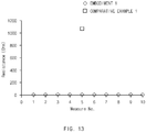
- Results obtained by inspecting torn defects of a separator by pressing an outer surface of an electrode assembly through a pressing jig were shown in Table 1 and also illustrated as a graph in FIG. 13 .
- the separator had a thickness of 20 um, and the torn portion had a size of 5 x 1 mm.
- the pressing jig was provided to adjust torque wrench and pressed so that a torque value has 20 kgfcm.
- a shaft to which pressing force is applied by the pressing jig was provided as a screw shaft to adjust the pressing force through the torque wrench.
- a multimeter was used as a measurement unit to measure a resistance value. Also, after being pressed through the pressing jig, the resistance value was measured 10 times under the same conditions by using the multimeter within 2 seconds, and the measured results were recorded. Here, the resistance was measured by electrically connecting both sides of the multimeter to electrodes disposed on both sides of the torn separator. That is, one side of the multimeter was connected to the electrode disposed above the separator, and the other side of the multimeter was connected to the electrode disposed below the separator to measure the resistance.
- Comparative Example 1 the resistance of the overflow (over the measurement limit) was shown at measurement orders 1 to 4 and orders 6 to 10, and the short circuit was not be detected.
- current does not flow between an upper electrode and a lower electrode with a separator therebetween by insulation of the separator.
- the upper electrode and the lower electrode may contact each other through a damaged portion of the separator to cause short circuit so that he current flows.
- resistance may be reduced, and thus, the reduction of the resistance may be detected to determine that the short circuit occurs.
- Embodiment 1 it is seen that all of the resistance values are measured during the 10 times of the measurement, and thus, the short circuit occurs at all of the 10 times of the resistance measurement through the damaged portion of the separator.
- Comparative Example 1 it is seen that all of the resistance values of overflow (over the measurement limit) are observed except for a resistance value (1,063 ohm) near 1000 ohm is measured only once (resistance value measurement order 5) in the 10 times of the measurement. That is, in the surface pressing manner according to Comparative Example 1, it is seen that only about 10% of the short circuit occurs through the damaged portion of the separator, and the apparatus for inspecting defects of the electrode assembly is remarkably deteriorated in reliability.
- Results obtained by inspecting torn defects of a separator by pressing an outer surface of an electrode assembly through a pressing jig were illustrated as a graph in FIG. 14 .
- the separator had a thickness of 20 um, and the torn portion had a size of 20 x 1 mm.
- the pressing jig was provided to adjust torque wrench and pressed so that a torque value has 4 kgfcm.
- a multimeter was used as a measurement unit to measure a resistance value. Also, after being pressed through the pressing jig, the resistance value was measured 12 times under the same conditions by using the multimeter within 2 seconds, and the measured results were recorded. Here, the resistance was measured by electrically connecting both sides of the multimeter to electrodes disposed on both sides of the torn separator. That is, one side of the multimeter was connected to the electrode disposed above the separator, and the other side of the multimeter was connected to the electrode disposed below the separator to measure the resistance.
- a resistance value overflow (over the measurement limit) was observed.
- a horizontal axis represents a measure order (No.)
- a vertical axis represents a resistance value.
- Comparative Example 2 when the resistance value is measured, the resistance value was observed at orders 4, 5, 8, 9, and 10, and thus, the short circuit was detected. That is, in Comparative Example 2, it is seen that the short circuit occurs at orders 4, 5, 8, 9, and 10. However, in Comparative Example 2, the resistance value of overflow (over measurement limit) was observed at orders 1, 2, 3, 6, 7, 11, and 12, and thus, the short circuit did not occur.
- a detection rate was higher than that in the surface pressing manner, but a detection rate of the short circuit was a level of about 42%. That is, it is seen that the short circuit occurs at the level of about 42% in the linear pressing manner according to Comparative Example 2.
Landscapes
- Physics & Mathematics (AREA)
- General Physics & Mathematics (AREA)
- Engineering & Computer Science (AREA)
- Manufacturing & Machinery (AREA)
- Chemical & Material Sciences (AREA)
- Chemical Kinetics & Catalysis (AREA)
- Electrochemistry (AREA)
- General Chemical & Material Sciences (AREA)
- Secondary Cells (AREA)
Priority Applications (1)
| Application Number | Priority Date | Filing Date | Title |
|---|---|---|---|
| EP21197283.1A EP3943962B1 (de) | 2017-07-11 | 2018-07-10 | Vorrichtung und verfahren zur inspektion des defekts einer sekundärbatterie |
Applications Claiming Priority (3)
| Application Number | Priority Date | Filing Date | Title |
|---|---|---|---|
| KR20170087842 | 2017-07-11 | ||
| KR1020180079155A KR102161028B1 (ko) | 2017-07-11 | 2018-07-09 | 이차전지의 불량 검사 장치 및 불량 검사 방법 |
| PCT/KR2018/007823 WO2019013534A1 (ko) | 2017-07-11 | 2018-07-10 | 이차전지의 불량 검사 장치 및 불량 검사 방법 |
Related Child Applications (2)
| Application Number | Title | Priority Date | Filing Date |
|---|---|---|---|
| EP21197283.1A Division EP3943962B1 (de) | 2017-07-11 | 2018-07-10 | Vorrichtung und verfahren zur inspektion des defekts einer sekundärbatterie |
| EP21197283.1A Division-Into EP3943962B1 (de) | 2017-07-11 | 2018-07-10 | Vorrichtung und verfahren zur inspektion des defekts einer sekundärbatterie |
Publications (3)
| Publication Number | Publication Date |
|---|---|
| EP3553544A1 true EP3553544A1 (de) | 2019-10-16 |
| EP3553544A4 EP3553544A4 (de) | 2020-03-18 |
| EP3553544B1 EP3553544B1 (de) | 2021-10-27 |
Family
ID=65277776
Family Applications (1)
| Application Number | Title | Priority Date | Filing Date |
|---|---|---|---|
| EP18832786.0A Active EP3553544B1 (de) | 2017-07-11 | 2018-07-10 | Fehlerüberprüfungsvorrichtung für wiederaufladbare batterie und fehlerüberprüfungsverfahren |
Country Status (4)
| Country | Link |
|---|---|
| US (1) | US11796595B2 (de) |
| EP (1) | EP3553544B1 (de) |
| KR (1) | KR102161028B1 (de) |
| CN (1) | CN110168390B (de) |
Cited By (1)
| Publication number | Priority date | Publication date | Assignee | Title |
|---|---|---|---|---|
| EP3907809A4 (de) * | 2019-09-18 | 2022-04-06 | LG Energy Solution, Ltd. | Presskurzschlussprüfgerät zur erkennung einer defekten niederspannungs-pouch-sekundärbatteriezelle |
Families Citing this family (14)
| Publication number | Priority date | Publication date | Assignee | Title |
|---|---|---|---|---|
| KR102814125B1 (ko) | 2019-10-14 | 2025-05-28 | 주식회사 엘지에너지솔루션 | 전기화학소자용 분리막의 절연 및 리튬 이온전도도 특성 평가 방법 및 시스템 |
| KR102821876B1 (ko) * | 2019-10-23 | 2025-06-18 | 주식회사 엘지에너지솔루션 | 가압식 분리막 저항 측정 장치 및 측정 방법 |
| KR102836398B1 (ko) * | 2019-10-30 | 2025-07-18 | 주식회사 엘지에너지솔루션 | 가압 지그 및 이를 이용한 이차전지 제조 방법 |
| KR102886200B1 (ko) | 2019-12-03 | 2025-11-13 | 주식회사 엘지에너지솔루션 | 가압 롤러를 포함하는 전지 불량 검사 장치 및 방법 |
| KR102795945B1 (ko) | 2020-01-10 | 2025-04-16 | 주식회사 엘지에너지솔루션 | 파우치형 전지셀의 불량 검사 장치 |
| DE102020112801A1 (de) * | 2020-05-12 | 2021-11-18 | Bayerische Motoren Werke Aktiengesellschaft | Verfahren zur Detektion von Feinschlüssen, Teststand und Fertigungslinie |
| KR102331861B1 (ko) | 2020-12-14 | 2021-12-01 | 한준희 | 2차 전지 검사장치 및 그 방법 |
| KR102886225B1 (ko) | 2021-02-09 | 2025-11-13 | 주식회사 엘지에너지솔루션 | 전해액 주액 전의 전극 조립체 불량 검사장치 및 불량 검사방법 |
| KR102929656B1 (ko) | 2021-07-14 | 2026-02-20 | 현대자동차주식회사 | 전극탭 접힘 판단 장치 및 판단 방법 |
| KR102886236B1 (ko) * | 2021-09-28 | 2025-11-14 | 주식회사 엘지에너지솔루션 | 전지셀 가압장치 |
| KR20230075796A (ko) | 2021-11-23 | 2023-05-31 | 주식회사 엘지에너지솔루션 | 이차전지용 가압단락 검사장치 |
| KR20230095312A (ko) * | 2021-12-22 | 2023-06-29 | 주식회사 엘지에너지솔루션 | 저전압 전지 셀의 이물 위치 검출 장치 및 이를 이용한 분석 방법 |
| KR20250151716A (ko) * | 2024-04-15 | 2025-10-22 | 삼성에스디아이 주식회사 | 이차전지용 분리막의 절연성 검사 장치 |
| KR20260001425A (ko) * | 2024-06-27 | 2026-01-05 | 주식회사 엘지에너지솔루션 | 파우치형 이차전지의 가압 장치 및 이를 이용한 가압 방법 |
Family Cites Families (23)
| Publication number | Priority date | Publication date | Assignee | Title |
|---|---|---|---|---|
| JP3364677B2 (ja) | 1998-07-14 | 2003-01-08 | ジャパンシステムエンジニアリング株式会社 | 二次電池の検査装置 |
| JP2005195159A (ja) * | 2004-01-09 | 2005-07-21 | Nsk Ltd | ボールねじ装置 |
| JP2008192497A (ja) | 2007-02-06 | 2008-08-21 | Matsushita Electric Ind Co Ltd | 内部短絡安全性評価方法及び内部短絡安全性評価装置並びに電池及び電池パック |
| KR101058388B1 (ko) * | 2007-02-08 | 2011-08-22 | 주식회사 엘지화학 | 이차전지 검사 장치 |
| KR101031186B1 (ko) * | 2007-12-12 | 2011-04-26 | 주식회사 엘지화학 | 전지팩용 시험장치 |
| JP2010153275A (ja) | 2008-12-26 | 2010-07-08 | Toyota Motor Corp | 2次電池の良否判定方法および製造方法 |
| CN102222801B (zh) * | 2010-04-13 | 2014-04-09 | 夏普株式会社 | 二次电池 |
| KR101359902B1 (ko) | 2011-01-31 | 2014-02-07 | 주식회사 엘지화학 | 전지셀 충방전용 지그 |
| EP2587897A1 (de) * | 2011-10-25 | 2013-05-01 | Easy Solution Holdings Limited | Steuerung für eine Fluoreszenzlampe |
| KR20130076119A (ko) | 2011-12-28 | 2013-07-08 | 주식회사 효성 | 전압측정이 가능한 밀봉 구조를 갖는 연료전지 장치 |
| JP6300319B2 (ja) * | 2012-02-29 | 2018-03-28 | Necエナジーデバイス株式会社 | 電池制御システム、電池パック、および電子機器 |
| KR101528001B1 (ko) | 2012-06-22 | 2015-06-10 | 주식회사 엘지화학 | 이차전지용 전극조립체, 그 제조방법 및 이를 이용한 이차전지 |
| CA2909568C (en) * | 2013-04-15 | 2016-11-22 | Nissan Motor Co., Ltd. | Fuel cell stack manufacturing method and manufacturing device |
| KR20150009876A (ko) * | 2013-07-17 | 2015-01-27 | 삼성에스디아이 주식회사 | 배터리의 리크 검사 장치 및 이를 이용한 배터리의 리크 검사 방법 |
| KR101526156B1 (ko) * | 2013-11-12 | 2015-06-04 | 유한회사 듀오콤 | 배터리 압축시험장치 및 배터리 압축시험방법 |
| KR101778829B1 (ko) * | 2013-11-29 | 2017-09-14 | 주식회사 엘지화학 | 단락 측정 장치 |
| JP5928441B2 (ja) * | 2013-12-19 | 2016-06-01 | トヨタ自動車株式会社 | 全固体電池の製造方法 |
| US20150268728A1 (en) | 2014-03-18 | 2015-09-24 | Fuji Xerox Co., Ltd. | Systems and methods for notifying users of mismatches between intended and actual captured content during heads-up recording of video |
| KR101442687B1 (ko) * | 2014-07-16 | 2014-09-23 | 주식회사 일우하이텍 | 2차 전지 압축시험기 |
| KR101790118B1 (ko) | 2014-12-05 | 2017-10-25 | 주식회사 엘지화학 | 전극조립체의 불량 유무 선별용 가압장치 및 불량 유무 선별방법 |
| CN205177965U (zh) * | 2015-11-09 | 2016-04-20 | 东莞市泰有源电池科技有限公司 | 一种电池充放电用夹具和装置 |
| KR101654102B1 (ko) * | 2016-01-07 | 2016-09-05 | 세방전지(주) | 전지모듈의 융착지그 |
| JP2017130283A (ja) * | 2016-01-18 | 2017-07-27 | トヨタ自動車株式会社 | 全固体電池 |
-
2018
- 2018-07-09 KR KR1020180079155A patent/KR102161028B1/ko active Active
- 2018-07-10 EP EP18832786.0A patent/EP3553544B1/de active Active
- 2018-07-10 US US16/476,787 patent/US11796595B2/en active Active
- 2018-07-10 CN CN201880005865.3A patent/CN110168390B/zh active Active
Cited By (1)
| Publication number | Priority date | Publication date | Assignee | Title |
|---|---|---|---|---|
| EP3907809A4 (de) * | 2019-09-18 | 2022-04-06 | LG Energy Solution, Ltd. | Presskurzschlussprüfgerät zur erkennung einer defekten niederspannungs-pouch-sekundärbatteriezelle |
Also Published As
| Publication number | Publication date |
|---|---|
| KR20190006920A (ko) | 2019-01-21 |
| KR102161028B1 (ko) | 2020-10-05 |
| US20190324089A1 (en) | 2019-10-24 |
| CN110168390A (zh) | 2019-08-23 |
| US11796595B2 (en) | 2023-10-24 |
| EP3553544A4 (de) | 2020-03-18 |
| CN110168390B (zh) | 2021-07-09 |
| EP3553544B1 (de) | 2021-10-27 |
Similar Documents
| Publication | Publication Date | Title |
|---|---|---|
| EP3553544B1 (de) | Fehlerüberprüfungsvorrichtung für wiederaufladbare batterie und fehlerüberprüfungsverfahren | |
| US10656212B2 (en) | Method of inspecting electric power storage device for short circuit and method of manufacturing electric power storage device | |
| CN109856555B (zh) | 蓄电设备的评价方法和制造方法、以及测试系统 | |
| KR20130126548A (ko) | 파우치형 이차 전지의 절연성 검사 방법 및 장치 | |
| KR101681968B1 (ko) | 이차 전지 평가 장치 | |
| US12044736B2 (en) | Vibration test jig and vibration test apparatus for cylindrical battery cell | |
| JP2014222603A (ja) | 電池の検査方法 | |
| CN104515954B (zh) | 二次电池的制造方法 | |
| KR20200059483A (ko) | 저전압 불량 전지셀 검출을 위한 가압단락 검사장치 | |
| US12174137B2 (en) | Welding quality inspection device | |
| US20050242820A1 (en) | Method for testing precursor of secondary cell, its testing instrument, and method for manufacturing secondary cell using the method | |
| CN112213650A (zh) | 蓄电设备的检查方法及制造方法 | |
| EP3943962B1 (de) | Vorrichtung und verfahren zur inspektion des defekts einer sekundärbatterie | |
| JP7011782B2 (ja) | 二次電池の検査方法 | |
| CN117321817A (zh) | 用于检测二次电池中的缺陷的设备和方法 | |
| JP7479465B2 (ja) | 溶接不良の検査方法 | |
| US12140638B2 (en) | Method for measuring cell performance | |
| KR20210069377A (ko) | 가압 롤러를 포함하는 전지 불량 검사 장치 및 방법 | |
| US20030154593A1 (en) | Method for manufacturing galvanic elements | |
| KR101787148B1 (ko) | 단위셀의 쇼트측정장치 | |
| KR100670455B1 (ko) | 이차 전지용 권취장치 | |
| JPH0367473A (ja) | 密閉形鉛蓄電池の検査方法 | |
| KR20240169592A (ko) | 절연성 검사 방법 및 장치 | |
| KR20220040198A (ko) | 이차 전지 검사 장치 및 방법 | |
| KR20170020275A (ko) | 배터리 셀용 전극 유닛, 배터리 셀, 및 배터리 셀 작동 방법 |
Legal Events
| Date | Code | Title | Description |
|---|---|---|---|
| STAA | Information on the status of an ep patent application or granted ep patent |
Free format text: STATUS: THE INTERNATIONAL PUBLICATION HAS BEEN MADE |
|
| PUAI | Public reference made under article 153(3) epc to a published international application that has entered the european phase |
Free format text: ORIGINAL CODE: 0009012 |
|
| STAA | Information on the status of an ep patent application or granted ep patent |
Free format text: STATUS: REQUEST FOR EXAMINATION WAS MADE |
|
| 17P | Request for examination filed |
Effective date: 20190710 |
|
| AK | Designated contracting states |
Kind code of ref document: A1 Designated state(s): AL AT BE BG CH CY CZ DE DK EE ES FI FR GB GR HR HU IE IS IT LI LT LU LV MC MK MT NL NO PL PT RO RS SE SI SK SM TR |
|
| AX | Request for extension of the european patent |
Extension state: BA ME |
|
| A4 | Supplementary search report drawn up and despatched |
Effective date: 20200219 |
|
| RIC1 | Information provided on ipc code assigned before grant |
Ipc: G01R 1/067 20060101ALI20200213BHEP Ipc: H01M 2/02 20060101ALI20200213BHEP Ipc: H01M 10/42 20060101ALI20200213BHEP Ipc: G01R 31/36 20200101AFI20200213BHEP |
|
| DAV | Request for validation of the european patent (deleted) | ||
| DAX | Request for extension of the european patent (deleted) | ||
| REG | Reference to a national code |
Ref country code: DE Ref legal event code: R079 Ref document number: 602018025859 Country of ref document: DE Free format text: PREVIOUS MAIN CLASS: G01R0031360000 Ipc: H01M0010420000 |
|
| RIC1 | Information provided on ipc code assigned before grant |
Ipc: H01M 50/20 20210101ALI20210408BHEP Ipc: G01R 31/36 20200101ALI20210408BHEP Ipc: G01R 1/067 20060101ALI20210408BHEP Ipc: H01M 10/42 20060101AFI20210408BHEP |
|
| GRAP | Despatch of communication of intention to grant a patent |
Free format text: ORIGINAL CODE: EPIDOSNIGR1 |
|
| STAA | Information on the status of an ep patent application or granted ep patent |
Free format text: STATUS: GRANT OF PATENT IS INTENDED |
|
| INTG | Intention to grant announced |
Effective date: 20210519 |
|
| GRAS | Grant fee paid |
Free format text: ORIGINAL CODE: EPIDOSNIGR3 |
|
| GRAA | (expected) grant |
Free format text: ORIGINAL CODE: 0009210 |
|
| STAA | Information on the status of an ep patent application or granted ep patent |
Free format text: STATUS: THE PATENT HAS BEEN GRANTED |
|
| AK | Designated contracting states |
Kind code of ref document: B1 Designated state(s): AL AT BE BG CH CY CZ DE DK EE ES FI FR GB GR HR HU IE IS IT LI LT LU LV MC MK MT NL NO PL PT RO RS SE SI SK SM TR |
|
| REG | Reference to a national code |
Ref country code: GB Ref legal event code: FG4D |
|
| REG | Reference to a national code |
Ref country code: CH Ref legal event code: EP |
|
| REG | Reference to a national code |
Ref country code: AT Ref legal event code: REF Ref document number: 1442651 Country of ref document: AT Kind code of ref document: T Effective date: 20211115 |
|
| REG | Reference to a national code |
Ref country code: DE Ref legal event code: R096 Ref document number: 602018025859 Country of ref document: DE |
|
| REG | Reference to a national code |
Ref country code: IE Ref legal event code: FG4D |
|
| RAP2 | Party data changed (patent owner data changed or rights of a patent transferred) |
Owner name: LG ENERGY SOLUTION LTD. |
|
| REG | Reference to a national code |
Ref country code: LT Ref legal event code: MG9D |
|
| REG | Reference to a national code |
Ref country code: NL Ref legal event code: MP Effective date: 20211027 |
|
| REG | Reference to a national code |
Ref country code: AT Ref legal event code: MK05 Ref document number: 1442651 Country of ref document: AT Kind code of ref document: T Effective date: 20211027 |
|
| RAP4 | Party data changed (patent owner data changed or rights of a patent transferred) |
Owner name: LG ENERGY SOLUTION, LTD. |
|
| PG25 | Lapsed in a contracting state [announced via postgrant information from national office to epo] |
Ref country code: RS Free format text: LAPSE BECAUSE OF FAILURE TO SUBMIT A TRANSLATION OF THE DESCRIPTION OR TO PAY THE FEE WITHIN THE PRESCRIBED TIME-LIMIT Effective date: 20211027 Ref country code: LT Free format text: LAPSE BECAUSE OF FAILURE TO SUBMIT A TRANSLATION OF THE DESCRIPTION OR TO PAY THE FEE WITHIN THE PRESCRIBED TIME-LIMIT Effective date: 20211027 Ref country code: FI Free format text: LAPSE BECAUSE OF FAILURE TO SUBMIT A TRANSLATION OF THE DESCRIPTION OR TO PAY THE FEE WITHIN THE PRESCRIBED TIME-LIMIT Effective date: 20211027 Ref country code: BG Free format text: LAPSE BECAUSE OF FAILURE TO SUBMIT A TRANSLATION OF THE DESCRIPTION OR TO PAY THE FEE WITHIN THE PRESCRIBED TIME-LIMIT Effective date: 20220127 Ref country code: AT Free format text: LAPSE BECAUSE OF FAILURE TO SUBMIT A TRANSLATION OF THE DESCRIPTION OR TO PAY THE FEE WITHIN THE PRESCRIBED TIME-LIMIT Effective date: 20211027 |
|
| PG25 | Lapsed in a contracting state [announced via postgrant information from national office to epo] |
Ref country code: IS Free format text: LAPSE BECAUSE OF FAILURE TO SUBMIT A TRANSLATION OF THE DESCRIPTION OR TO PAY THE FEE WITHIN THE PRESCRIBED TIME-LIMIT Effective date: 20220227 Ref country code: SE Free format text: LAPSE BECAUSE OF FAILURE TO SUBMIT A TRANSLATION OF THE DESCRIPTION OR TO PAY THE FEE WITHIN THE PRESCRIBED TIME-LIMIT Effective date: 20211027 Ref country code: PT Free format text: LAPSE BECAUSE OF FAILURE TO SUBMIT A TRANSLATION OF THE DESCRIPTION OR TO PAY THE FEE WITHIN THE PRESCRIBED TIME-LIMIT Effective date: 20220228 Ref country code: PL Free format text: LAPSE BECAUSE OF FAILURE TO SUBMIT A TRANSLATION OF THE DESCRIPTION OR TO PAY THE FEE WITHIN THE PRESCRIBED TIME-LIMIT Effective date: 20211027 Ref country code: NO Free format text: LAPSE BECAUSE OF FAILURE TO SUBMIT A TRANSLATION OF THE DESCRIPTION OR TO PAY THE FEE WITHIN THE PRESCRIBED TIME-LIMIT Effective date: 20220127 Ref country code: NL Free format text: LAPSE BECAUSE OF FAILURE TO SUBMIT A TRANSLATION OF THE DESCRIPTION OR TO PAY THE FEE WITHIN THE PRESCRIBED TIME-LIMIT Effective date: 20211027 Ref country code: LV Free format text: LAPSE BECAUSE OF FAILURE TO SUBMIT A TRANSLATION OF THE DESCRIPTION OR TO PAY THE FEE WITHIN THE PRESCRIBED TIME-LIMIT Effective date: 20211027 Ref country code: HR Free format text: LAPSE BECAUSE OF FAILURE TO SUBMIT A TRANSLATION OF THE DESCRIPTION OR TO PAY THE FEE WITHIN THE PRESCRIBED TIME-LIMIT Effective date: 20211027 Ref country code: GR Free format text: LAPSE BECAUSE OF FAILURE TO SUBMIT A TRANSLATION OF THE DESCRIPTION OR TO PAY THE FEE WITHIN THE PRESCRIBED TIME-LIMIT Effective date: 20220128 Ref country code: ES Free format text: LAPSE BECAUSE OF FAILURE TO SUBMIT A TRANSLATION OF THE DESCRIPTION OR TO PAY THE FEE WITHIN THE PRESCRIBED TIME-LIMIT Effective date: 20211027 |
|
| REG | Reference to a national code |
Ref country code: DE Ref legal event code: R097 Ref document number: 602018025859 Country of ref document: DE |
|
| PG25 | Lapsed in a contracting state [announced via postgrant information from national office to epo] |
Ref country code: SM Free format text: LAPSE BECAUSE OF FAILURE TO SUBMIT A TRANSLATION OF THE DESCRIPTION OR TO PAY THE FEE WITHIN THE PRESCRIBED TIME-LIMIT Effective date: 20211027 Ref country code: SK Free format text: LAPSE BECAUSE OF FAILURE TO SUBMIT A TRANSLATION OF THE DESCRIPTION OR TO PAY THE FEE WITHIN THE PRESCRIBED TIME-LIMIT Effective date: 20211027 Ref country code: RO Free format text: LAPSE BECAUSE OF FAILURE TO SUBMIT A TRANSLATION OF THE DESCRIPTION OR TO PAY THE FEE WITHIN THE PRESCRIBED TIME-LIMIT Effective date: 20211027 Ref country code: EE Free format text: LAPSE BECAUSE OF FAILURE TO SUBMIT A TRANSLATION OF THE DESCRIPTION OR TO PAY THE FEE WITHIN THE PRESCRIBED TIME-LIMIT Effective date: 20211027 Ref country code: DK Free format text: LAPSE BECAUSE OF FAILURE TO SUBMIT A TRANSLATION OF THE DESCRIPTION OR TO PAY THE FEE WITHIN THE PRESCRIBED TIME-LIMIT Effective date: 20211027 Ref country code: CZ Free format text: LAPSE BECAUSE OF FAILURE TO SUBMIT A TRANSLATION OF THE DESCRIPTION OR TO PAY THE FEE WITHIN THE PRESCRIBED TIME-LIMIT Effective date: 20211027 |
|
| PLBE | No opposition filed within time limit |
Free format text: ORIGINAL CODE: 0009261 |
|
| STAA | Information on the status of an ep patent application or granted ep patent |
Free format text: STATUS: NO OPPOSITION FILED WITHIN TIME LIMIT |
|
| 26N | No opposition filed |
Effective date: 20220728 |
|
| PG25 | Lapsed in a contracting state [announced via postgrant information from national office to epo] |
Ref country code: AL Free format text: LAPSE BECAUSE OF FAILURE TO SUBMIT A TRANSLATION OF THE DESCRIPTION OR TO PAY THE FEE WITHIN THE PRESCRIBED TIME-LIMIT Effective date: 20211027 |
|
| PG25 | Lapsed in a contracting state [announced via postgrant information from national office to epo] |
Ref country code: SI Free format text: LAPSE BECAUSE OF FAILURE TO SUBMIT A TRANSLATION OF THE DESCRIPTION OR TO PAY THE FEE WITHIN THE PRESCRIBED TIME-LIMIT Effective date: 20211027 |
|
| PG25 | Lapsed in a contracting state [announced via postgrant information from national office to epo] |
Ref country code: MC Free format text: LAPSE BECAUSE OF FAILURE TO SUBMIT A TRANSLATION OF THE DESCRIPTION OR TO PAY THE FEE WITHIN THE PRESCRIBED TIME-LIMIT Effective date: 20211027 |
|
| REG | Reference to a national code |
Ref country code: CH Ref legal event code: PL |
|
| REG | Reference to a national code |
Ref country code: BE Ref legal event code: MM Effective date: 20220731 |
|
| PG25 | Lapsed in a contracting state [announced via postgrant information from national office to epo] |
Ref country code: LU Free format text: LAPSE BECAUSE OF NON-PAYMENT OF DUE FEES Effective date: 20220710 Ref country code: LI Free format text: LAPSE BECAUSE OF NON-PAYMENT OF DUE FEES Effective date: 20220731 Ref country code: CH Free format text: LAPSE BECAUSE OF NON-PAYMENT OF DUE FEES Effective date: 20220731 |
|
| REG | Reference to a national code |
Ref country code: DE Ref legal event code: R081 Ref document number: 602018025859 Country of ref document: DE Owner name: LG ENERGY SOLUTION, LTD., KR Free format text: FORMER OWNER: LG CHEM, LTD., SEOUL, KR |
|
| PG25 | Lapsed in a contracting state [announced via postgrant information from national office to epo] |
Ref country code: IT Free format text: LAPSE BECAUSE OF FAILURE TO SUBMIT A TRANSLATION OF THE DESCRIPTION OR TO PAY THE FEE WITHIN THE PRESCRIBED TIME-LIMIT Effective date: 20211027 Ref country code: BE Free format text: LAPSE BECAUSE OF NON-PAYMENT OF DUE FEES Effective date: 20220731 |
|
| P01 | Opt-out of the competence of the unified patent court (upc) registered |
Effective date: 20230512 |
|
| PG25 | Lapsed in a contracting state [announced via postgrant information from national office to epo] |
Ref country code: IE Free format text: LAPSE BECAUSE OF NON-PAYMENT OF DUE FEES Effective date: 20220710 |
|
| REG | Reference to a national code |
Ref country code: GB Ref legal event code: 732E Free format text: REGISTERED BETWEEN 20230901 AND 20230906 |
|
| PG25 | Lapsed in a contracting state [announced via postgrant information from national office to epo] |
Ref country code: HU Free format text: LAPSE BECAUSE OF FAILURE TO SUBMIT A TRANSLATION OF THE DESCRIPTION OR TO PAY THE FEE WITHIN THE PRESCRIBED TIME-LIMIT; INVALID AB INITIO Effective date: 20180710 |
|
| PG25 | Lapsed in a contracting state [announced via postgrant information from national office to epo] |
Ref country code: MK Free format text: LAPSE BECAUSE OF FAILURE TO SUBMIT A TRANSLATION OF THE DESCRIPTION OR TO PAY THE FEE WITHIN THE PRESCRIBED TIME-LIMIT Effective date: 20211027 Ref country code: CY Free format text: LAPSE BECAUSE OF FAILURE TO SUBMIT A TRANSLATION OF THE DESCRIPTION OR TO PAY THE FEE WITHIN THE PRESCRIBED TIME-LIMIT Effective date: 20211027 |
|
| PG25 | Lapsed in a contracting state [announced via postgrant information from national office to epo] |
Ref country code: MT Free format text: LAPSE BECAUSE OF FAILURE TO SUBMIT A TRANSLATION OF THE DESCRIPTION OR TO PAY THE FEE WITHIN THE PRESCRIBED TIME-LIMIT Effective date: 20211027 |
|
| PGFP | Annual fee paid to national office [announced via postgrant information from national office to epo] |
Ref country code: GB Payment date: 20250624 Year of fee payment: 8 |
|
| PGFP | Annual fee paid to national office [announced via postgrant information from national office to epo] |
Ref country code: FR Payment date: 20250624 Year of fee payment: 8 |
|
| PGFP | Annual fee paid to national office [announced via postgrant information from national office to epo] |
Ref country code: DE Payment date: 20250624 Year of fee payment: 8 |
|
| PG25 | Lapsed in a contracting state [announced via postgrant information from national office to epo] |
Ref country code: TR Free format text: LAPSE BECAUSE OF FAILURE TO SUBMIT A TRANSLATION OF THE DESCRIPTION OR TO PAY THE FEE WITHIN THE PRESCRIBED TIME-LIMIT Effective date: 20211027 |