EP4389946B1 - Vorrichtung zur herstellung von filamenten - Google Patents
Vorrichtung zur herstellung von filamenten Download PDFInfo
- Publication number
- EP4389946B1 EP4389946B1 EP22215646.5A EP22215646A EP4389946B1 EP 4389946 B1 EP4389946 B1 EP 4389946B1 EP 22215646 A EP22215646 A EP 22215646A EP 4389946 B1 EP4389946 B1 EP 4389946B1
- Authority
- EP
- European Patent Office
- Prior art keywords
- distributor
- plate
- spinneret
- openings
- width
- Prior art date
- Legal status (The legal status is an assumption and is not a legal conclusion. Google has not performed a legal analysis and makes no representation as to the accuracy of the status listed.)
- Active
Links
Images

Classifications
-
- D—TEXTILES; PAPER
- D01—NATURAL OR MAN-MADE THREADS OR FIBRES; SPINNING
- D01D—MECHANICAL METHODS OR APPARATUS IN THE MANUFACTURE OF ARTIFICIAL FILAMENTS, THREADS, FIBRES, BRISTLES OR RIBBONS
- D01D4/00—Spinnerette packs; Cleaning thereof
- D01D4/06—Distributing spinning solution or melt to spinning nozzles
-
- D—TEXTILES; PAPER
- D01—NATURAL OR MAN-MADE THREADS OR FIBRES; SPINNING
- D01D—MECHANICAL METHODS OR APPARATUS IN THE MANUFACTURE OF ARTIFICIAL FILAMENTS, THREADS, FIBRES, BRISTLES OR RIBBONS
- D01D1/00—Treatment of filament-forming or like material
- D01D1/10—Filtering or de-aerating the spinning solution or melt
- D01D1/106—Filtering
-
- D—TEXTILES; PAPER
- D01—NATURAL OR MAN-MADE THREADS OR FIBRES; SPINNING
- D01D—MECHANICAL METHODS OR APPARATUS IN THE MANUFACTURE OF ARTIFICIAL FILAMENTS, THREADS, FIBRES, BRISTLES OR RIBBONS
- D01D4/00—Spinnerette packs; Cleaning thereof
-
- D—TEXTILES; PAPER
- D01—NATURAL OR MAN-MADE THREADS OR FIBRES; SPINNING
- D01D—MECHANICAL METHODS OR APPARATUS IN THE MANUFACTURE OF ARTIFICIAL FILAMENTS, THREADS, FIBRES, BRISTLES OR RIBBONS
- D01D4/00—Spinnerette packs; Cleaning thereof
- D01D4/02—Spinnerettes
-
- D—TEXTILES; PAPER
- D01—NATURAL OR MAN-MADE THREADS OR FIBRES; SPINNING
- D01D—MECHANICAL METHODS OR APPARATUS IN THE MANUFACTURE OF ARTIFICIAL FILAMENTS, THREADS, FIBRES, BRISTLES OR RIBBONS
- D01D4/00—Spinnerette packs; Cleaning thereof
- D01D4/02—Spinnerettes
- D01D4/022—Processes or materials for the preparation of spinnerettes
-
- D—TEXTILES; PAPER
- D01—NATURAL OR MAN-MADE THREADS OR FIBRES; SPINNING
- D01D—MECHANICAL METHODS OR APPARATUS IN THE MANUFACTURE OF ARTIFICIAL FILAMENTS, THREADS, FIBRES, BRISTLES OR RIBBONS
- D01D4/00—Spinnerette packs; Cleaning thereof
- D01D4/08—Supporting spinnerettes or other parts of spinnerette packs
-
- D—TEXTILES; PAPER
- D01—NATURAL OR MAN-MADE THREADS OR FIBRES; SPINNING
- D01D—MECHANICAL METHODS OR APPARATUS IN THE MANUFACTURE OF ARTIFICIAL FILAMENTS, THREADS, FIBRES, BRISTLES OR RIBBONS
- D01D5/00—Formation of filaments, threads, or the like
- D01D5/08—Melt spinning methods
- D01D5/098—Melt spinning methods with simultaneous stretching
- D01D5/0985—Melt spinning methods with simultaneous stretching by means of a flowing gas (e.g. melt-blowing)
-
- D—TEXTILES; PAPER
- D01—NATURAL OR MAN-MADE THREADS OR FIBRES; SPINNING
- D01D—MECHANICAL METHODS OR APPARATUS IN THE MANUFACTURE OF ARTIFICIAL FILAMENTS, THREADS, FIBRES, BRISTLES OR RIBBONS
- D01D5/00—Formation of filaments, threads, or the like
- D01D5/28—Formation of filaments, threads, or the like while mixing different spinning solutions or melts during the spinning operation; Spinnerette packs therefor
- D01D5/30—Conjugate filaments; Spinnerette packs therefor
-
- D—TEXTILES; PAPER
- D04—BRAIDING; LACE-MAKING; KNITTING; TRIMMINGS; NON-WOVEN FABRICS
- D04H—MAKING TEXTILE FABRICS, e.g. FROM FIBRES OR FILAMENTARY MATERIAL; FABRICS MADE BY SUCH PROCESSES OR APPARATUS, e.g. FELTS, NON-WOVEN FABRICS; COTTON-WOOL; WADDING ; NON-WOVEN FABRICS FROM STAPLE FIBRES, FILAMENTS OR YARNS, BONDED WITH AT LEAST ONE WEB-LIKE MATERIAL DURING THEIR CONSOLIDATION
- D04H3/00—Non-woven fabrics formed wholly or mainly of yarns or like filamentary material of substantial length
- D04H3/08—Non-woven fabrics formed wholly or mainly of yarns or like filamentary material of substantial length characterised by the method of strengthening or consolidating
- D04H3/16—Non-woven fabrics formed wholly or mainly of yarns or like filamentary material of substantial length characterised by the method of strengthening or consolidating with bonds between thermoplastic filaments produced in association with filament formation, e.g. immediately following extrusion
Definitions
- the invention relates to a device for producing filaments, in particular filaments made of thermoplastic material, wherein the device has at least one spinneret plate and wherein the filaments emerge in at least one filament row from spinneret openings of this spinneret plate.
- the invention relates to a device for producing spunbonded nonwovens or nonwoven webs from filaments made of thermoplastic material.
- the filaments are preferably continuous filaments. Continuous filaments differ from short fibers due to their quasi-continuous length, which have significantly shorter lengths of, for example, 1 mm to 60 mm. It is within the scope of the invention that the filaments are deposited on a conveyor device, preferably on a depositing sieve belt. The width of a product deposited on such a conveyor device depends in particular on the spinning width. Spinning width means in particular the width of a filament row emerging from spinneret openings of the spinneret plate.
- Devices of the type mentioned above are basically known from practice in different embodiments. It is often desirable to variably adjust the fleece web width and thus the spinning width of the devices. This is possible, for example, with segmented devices in which there are a number of distribution devices lined up across the spinning width, which are switched on or off as required. However, this design has the disadvantage that plastic residues remain in the switched off device segments, which can lead to contamination of the device and ultimately to malfunctions in the device operation.
- EP 1 486 591 A1 a device in which at least one distribution device for Distribution of a supplied plastic melt over a preliminary spinning width is provided, wherein the distribution device is followed by a distribution plate package made up of distribution plates, wherein the individual distribution plates each have a plurality of distribution openings distributed over a distribution width and wherein the distribution plate package is followed by a spinneret plate which has spinneret channels with the associated spinneret openings distributed over a final spinning width.
- the distribution plate package By means of the distribution plate package, a reduction or expansion of the preliminary spinning width to a final spinning width can be achieved.
- the interchangeability of the distribution plates and the spinneret plate enables a variable setting of the final spinning width.
- the plastic melt flows from the distribution device through the distribution openings of the distribution plates to the spinneret plate.
- the different thermal expansions of the distributor plates can lead to the fact that the distributor openings of adjacent distributor plates arranged one above the other are no longer arranged or oriented in the intended manner and, for example, are no longer aligned with one another. This can lead to an uneven distribution of the plastic melt and ultimately to spinning defects such as drop formation and the like.
- the distributor plate package is usually screwed all the way around the edge, the different thermal expansions of the distributor plates can nevertheless be observed to a considerable extent in the known devices and often have a detrimental effect on the spinning process.
- the described different thermal expansions of the distributor plates can also occur as a result of thermal cleaning processes of the device. Further relevant information can be found in the documents DE 44 19 555 and US 3 460 199 . - This is where the invention comes in.
- the invention is based on the technical problem of specifying a device of the type mentioned at the outset in which the disadvantages described above can be effectively and reliably avoided and in which disadvantageous influences on the spinning process resulting in particular from different thermal expansion of the distributor plates can be reduced or avoided.
- the term final spinning width refers in particular to the total width of a row of filaments emerging from the device and thus to the width of the row of associated spinneret openings.
- the term provisional spinning width refers in particular to the width or spinning width at the end of the distribution device on the filter plate side.
- spinning width is used to indicate the direction instead of the terms provisional spinning width and/or final spinning width.
- the extent or width of a row of distribution openings of a distribution plate within the scope of the invention defines a distribution width associated with this distribution plate.
- only one distribution device is provided in the direction transverse to the machine direction (CD) or in relation to the spinning width, which is expediently preceded by only one spinning pump for the plastic melt.
- the device is designed or set up according to a particularly preferred embodiment for producing multi-component filaments, in particular bicomponent filaments, it is expedient for the device to have at least two distribution devices arranged next to one another in the machine direction (MD). Then each of these distribution devices is preferably preceded by a separate spinning pump for the respective plastic melt.
- two or more distribution devices to be arranged next to one another across the spinning width or transverse to the machine direction (CD), and each distribution device can be preceded by a separate spinning pump.
- Machine direction (MD) or MD direction in the context of the invention means in particular the conveying direction of a conveying device for the filaments or the nonwoven web and thus the direction transverse to the provisional or final spinning width.
- CD or CD direction means in particular the direction transverse to the machine direction or the direction along the spinning width. It is expedient to produce several rows of filaments next to each other in the machine direction (MD) or transverse to the spinning width, each over the final spinning width. For this purpose, It is recommended that rows of spinneret openings be arranged next to one another in the machine direction. The spinneret openings of adjacent rows are preferably arranged offset from one another.
- the at least one distribution device is designed as a coat hanger distributor.
- the plastic melt is initially fed through a feed channel that is narrow in relation to the spinning width and experiences a gradual increase in width to the preliminary spinning width, taking into account a uniform flow profile at the outlet of the plastic melt from the coat hanger distributor, in particular by the fact that the same counterpressure is realized at each outlet point of the plastic melt.
- At least one filter plate is provided downstream of the distribution device.
- the filter plate preferably has perforated channels for the plastic melt.
- the perforated channels expediently extend transversely, in particular perpendicularly to the flat extension of the filter plate.
- the perforated channels of the filter plate are recommended to be arranged in at least one row extending in the direction of the preliminary spinning width.
- the filter plate can also have other designs within the scope of the invention.
- a distributor plate package of distributor plates is arranged downstream of the filter plate.
- Distributor plate package means a package of at least two, preferably at least three, preferably at least four, very particularly preferably at least five, for example at least six, distributor plates arranged one above the other. It is preferred that the device has no further distributor plates apart from the distributor plates of the distributor plate package. Then the distributor plate package of the The filter plate is located immediately downstream and the spinneret plate is located immediately upstream. In principle, at least one further distributor plate could be provided upstream and/or downstream of the distributor plate package.
- the expression exit surface of the filter plate means in particular the exit surface of the filter plate associated with the distributor plate package or the top distributor plate.
- the exit surface of the filter plate therefore expediently also means the exit side of the filter plate.
- the exit surface of the filter plate is in direct contact with the distributor plate package or the top distributor plate.
- the expression entry surface of the spinneret plate means in particular the surface of the spinneret plate associated with the distributor plate package or the last distributor plate.
- the entry surface of the spinneret plate therefore expediently also means the entry side of the spinneret plate.
- the entry surface of the spinneret plate is in direct contact with the distributor plate package or the bottom distributor plate.
- the outlet surface of the filter plate associated with the distributor plate package and/or the inlet surface of the spinneret plate associated with the distributor plate package is curved or spherical at least in sections. It is preferred that at least the outlet surface of the filter plate, in particular the outlet surface of the filter plate, is curved or spherical at least in sections. Curved or spherical in the context of the invention means curved or spherical in particular in the direction of the distributor plate package and thus preferably convexly curved.
- the outlet surface of the filter plate and/or the inlet surface is expediently the spinneret plate is curved or ground into a crown.
- the outlet surface of the filter plate and/or the inlet surface of the spinneret plate is therefore not flat, but rounded, so that within the scope of the invention a convex design of the outlet surface of the filter plate and/or the inlet surface of the spinneret plate is obtained, oriented in the direction of the distributor plate package.
- manufacturing tolerances for example the flatness of the individual components of the device, can be compensated.
- the outlet surface of the filter plate and/or the inlet surface of the spinneret plate is curved or spherical in relation to its extension in the machine direction (MD) at least in a middle section or central section.
- the outlet surface of the filter plate and/or the inlet surface of the spinneret plate is very particularly preferably curved or spherical over its entire or substantially over its entire extension in the machine direction (MD).
- the curvature or spherical shape described above is thus realized within the scope of the invention according to a preferred embodiment over the entire or substantially over the entire extension of the outlet surface of the filter plate and/or the inlet surface of the spinneret plate in the machine direction (MD).
- the curved, in particular the convex curved or spherical design of the filter plate and/or the spinneret plate thus expediently extends with respect to the conveying direction or the machine direction (MD) from the inlet side to the outlet side of the filter plate and/or the spinneret plate.
- MD machine direction
- This design also has the advantage that additional screwing can be avoided in this central section or middle section, which would otherwise counteract the realization of a homogeneous spinning field.
- a plurality of screws are provided for connecting the distributor plates of the distributor plate package and/or for connecting the unit made up of the distributor plate package and the spinneret plate and/or filter plate, which preferably pass through this unit and are arranged at least in the outer edge areas of the unit extending in the CD direction and are particularly preferably arranged around the edge of the unit. Due to the curved or spherical design of the filter plate and/or the spinneret plate, the contact pressure of these screws is preferably shifted from the outer edge areas of the unit, in particular from the outer edge areas of the unit extending in the CD direction, along the machine direction (MD) to the center of the unit.
- MD machine direction
- point loads in the area of the screws are expediently converted into a line load.
- the integral of the line loads forms a uniform surface pressure within the area enclosed by the screws, which are preferably arranged around the edge, which in particular ensures that the surface pressure acts evenly on the assembly consisting of the distributor plate package and the spinneret plate and/or filter plate.
- the surface pressure the interfaces of the individual levels between the distributor plates of the distributor plate package and between the distributor plate package and the spinneret plate and/or between the distributor plate package and the filter plate are preferably pressed evenly.
- the distance between adjacent screws is preferably selected accordingly. This applies in particular depending on the width of the unit or the spinneret plate in the machine direction (MD). For example, the wider the spinneret plate is in the MD direction, the smaller the screw spacing should preferably be in the CD direction.
- the screw diameter and the flange thickness of the screws are also preferably selected accordingly and adapted to the surface pressure.
- the distance between two screws that are arranged adjacently in the outer edge areas of the unit consisting of distributor plate package and spinneret plate and/or filter plate, which extend in the CD direction is between 20 mm and 70 mm, preferably between 25 mm and 60 mm, particularly preferably between 30 mm and 55 mm.
- Distance between two adjacent screws means in particular the center distance or flange center distance of the screws.
- the distance between two adjacent screws is identical or essentially identical along the entire extension in the CD direction. In principle, however, the distance between two adjacent screws along the extension in the CD direction can also be partially different.
- the curved or spherical design of the filter plate and/or the spinneret plate described above is expediently implemented in the machine direction (MD) along the entire extension or essentially along the entire extension of the filter plate and/or the spinneret plate transverse to the machine direction (CD), i.e. in the direction of the spinning width.
- MD machine direction
- CD machine direction
- the additional bracing of the distributor plates achieved by the curved or spherical design of the filter plate and/or the spinneret plate in the machine direction (MD) can be achieved along the entire extension of the device transverse to the machine direction (CD) or along the entire spinning width.
- the radius of curvature of the curved or spherical section of the outlet surface of the filter plate and/or the inlet surface of the spinneret plate is constant or essentially constant over the entire extent of the curved or spherical section. If the outlet surface of the filter plate and/or the inlet surface of the spinneret plate is curved or spherical over its entire or essentially over its entire extent in the machine direction (MD), the radius of curvature of this curved or spherical outlet surface of the filter plate and/or inlet surface of the spinneret plate is constant or essentially constant over the entire extent in the machine direction (MD).
- the radius of curvature of the curved or spherical section of the outlet surface of the filter plate and/or the inlet surface of the spinneret plate is 10,000 mm to 55,000 mm, preferably 12,000 mm to 45,000 mm, particularly preferably 14,000 mm to 40,000 mm, very particularly preferably 16,000 mm to 36,000 mm, for example 17,000 mm to 19,000 mm.
- a spinneret plate of a For an exemplary width of 240 mm in the machine direction (MD), the contact pressure is advantageously significantly higher than for a spinneret plate with an exemplary width of 120 mm in the machine direction (MD).
- the device according to the invention has at least one form-locking element that passes through the filter plate and/or the distributor plate package and/or the spinneret plate in the flow direction of the plastic melt, in particular completely passes through the distributor plate package.
- the distributor plates expediently each have at least one corresponding form-locking opening that is assigned to the at least one form-locking element.
- at least two, particularly preferably at least three, very particularly preferably a plurality of such form-locking elements and form-locking openings are provided for the device according to the invention or for the distributor plate package.
- the at least one form-locking element is a dowel pin.
- This embodiment of the device according to the invention with form-locking elements and form-locking openings is based on the knowledge that different thermal expansion of the distributor plates is additionally counteracted by form-locking, so that in particular a combination of force-locking - due to the curved or spherical design of the filter plate and/or the spinneret plate according to the invention - and form-locking is realized.
- the invention relates in particular to a device for producing spunbonded nonwovens from filaments made of thermoplastic material.
- the device according to the invention is designed as a spunbond device and then spunbond nonwovens or nonwoven webs are expediently produced with the device according to the invention.
- Monocomponent filaments and/or mixed filaments and/or multicomponent filaments, in particular bicomponent filaments are produced as continuous filaments.
- the term mixed filament refers in particular to a filament which is designed as a mono-type filament in terms of its cross-sectional configuration, but consists of a mixture of at least two plastics or plastic melts.
- a cooling device for cooling the filaments produced downstream of the spinneret plate which preferably has a cooling chamber through which the filaments or continuous filaments produced are guided for cooling. It is preferred that air supply cabins for supplying the cooling air are arranged on two opposite sides of the cooling chamber. According to a preferred embodiment, air supply cabins arranged one above the other are present on two opposite sides of the cooling chamber, in particular two air supply cabins arranged one above the other, from which air of different temperatures is preferably introduced into the cooling chamber. It has also proven useful to provide a monomer extraction device between the spinneret plate and the cooling device, with which disruptive gases that occur during the spinning process can be removed from the device or the spunbond device.
- a stretching device for stretching the filaments produced is expediently arranged downstream of the cooling device in the direction of filament flow.
- the unit comprising the cooling device and the stretching device is designed as a closed unit in which, apart from the supply of cooling air in the cooling device, no further air is supplied to the closed unit.
- At least one diffuser is arranged between the stretching device and the conveyor device, in particular the depositing screen belt.
- the continuous filaments emerging from the stretching device are guided through the diffuser and then deposited on the conveyor device.
- two diffusers connected in series are provided.
- the conveyor device is also preferably designed as an endlessly rotating conveyor device or as an endlessly rotating depositing screen belt.
- the conveyor device, in particular the depositing screen belt is particularly preferably designed to be permeable to air, so that process air can be extracted from below through the conveyor device.
- a particularly preferred embodiment of the invention is characterized in that the at least one spinneret plate is designed as an exchangeable spinneret plate.
- the distributor plates are also preferably designed to be exchangeable. In this way, the desired final spinning width can be set by suitable selection and exchange of the distributor plates and the spinneret plate.
- the distribution width formed by the distributor openings of at least one distributor plate, preferably a plurality of distributor plates, preferably each distributor plate of the distributor plate package is smaller or larger than the provisional spinning width, so that the provisional spinning width is reduced or expanded to the final spinning width with the help of the distributor plate package and the desired final spinning width can be set preferably by exchanging the distributor plates or the distributor plate package.
- the distributor openings of the distributor plates are expediently arranged vertically or perpendicularly to the distributor plate surface. It is also preferred that at least part of the Distributor plates of the distributor plate package, the distributor openings open into distribution channels, which lead to an expansion or reduction of the inlet-side distribution width. The extent or width of a row of distributor openings defines the distribution width for the respective distributor plate.
- the distribution widths formed by the distribution openings of the individual distribution plates decrease or increase from the filter plate to the spinneret plate, so that the preliminary spinning width is reduced or expanded in this way to the final spinning width. It is also within the scope of the invention that a distribution plate has several rows of distribution openings arranged next to one another. Each row of distribution openings expediently extends over the distribution width of the respective distribution plate. The distribution openings of two rows of distribution openings arranged next to one another in the conveying direction or machine direction (MD) are preferably arranged offset from one another.
- MD machine direction
- a particularly preferred embodiment of the invention is characterized in that at least one of the distributor plates has at least one distributor channel which extends over at least part of the distribution width, which distributor channel connects at least part of the distributor openings to one another. It is within the scope of the invention that the distributor channel connects the distributor openings arranged in a row with respect to the distribution width.
- the distributor channel expediently extends over the entire distribution width of the distributor plate and preferably connects all the distributor openings of this distributor plate arranged in a row.
- the distributor openings of each row are connected to one another by a distributor channel.
- a distributor channel is preferably horizontal or perpendicular to the distributor openings.
- a distributor channel adjacent to an adjacent distributor plate expediently connects at least some of the distributor openings of the adjacent distributor plate arranged in a row and preferably all of the distributor openings of this adjacent distributor plate arranged in a row.
- the above-described design of a distributor plate with distributor openings and distributor channels is preferably implemented in at least one of the distributor plates of the distributor plate package and preferably in at least a portion, particularly preferably in at least a majority, of the distributor plates of the distributor plate package.
- the distributor channels serve in particular to distribute the plastic melt in the direction or along the distribution widths to expand or reduce the preliminary spinning width.
- a further preferred embodiment of the invention is characterized in that at least one of the distributor plates of the distributor plate package, preferably a part of the distributor plates of the distributor plate package, has no distributor channels.
- This is preferably at least one distributor plate of the distributor plate package assigned to the spinneret plate and thus at least one lower distributor plate of the distributor plate package, for example the last distributor plate of the distributor plate package assigned to the spinneret plate.
- the preliminary spinning width is reduced or expanded to the desired distribution width or final spinning width by a part of the distributor plates, which are expediently provided with corresponding distributor channels, and the distributor plates downstream in the flow direction of the plastic melt can - in particular without any significant further influence the final spinning width - to further influence the plastic melt, for example to combine at least two plastic melts to produce multi-component filaments or to reduce the diameter of the distributor openings and the like. It has also proven useful that at least in some of the distributor plates of the distributor plate package, the distributor openings of adjacent distributor plates arranged one above the other are offset from one another with respect to the distribution width. This is particularly the case with the distributor plates of the distributor plate package that have distributor channels.
- the at least one plastic melt preferably flows through the flow paths formed by the distributor plates or the distributor plate package from distributor openings and distributor channels and exits above the spinneret plate, in particular immediately above the spinneret plate, from the distributor openings of a distributor plate or the last distributor plate of the distributor plate package and into associated spinneret channels of the spinneret plate.
- the flow paths for the at least one plastic melt - in particular with regard to the flow path length and/or the cross-sectional geometry of the distributor channels or the distributor openings and/or with regard to the cross-sectional area of the distributor channels or the distributor openings - are designed with the proviso that at the exit of the plastic melt from the distributor plate package or at the entry into the spinneret channels of the spinneret plate, the same or essentially the same counterpressure is present at each distributor opening and/or at each spinneret channel.
- the counterpressure is thus preferably adjusted by the design of the flow paths which are assigned to the individual spinneret channels and in particular to the filaments produced.
- the filter plate according to the invention is preferably designed to support a filter.
- the filter is expediently arranged between the at least one distribution device and the filter plate and thus downstream of the distribution device in the flow direction of the plastic melt.
- a close-meshed filter sieve is preferably used as the filter.
- a plurality of heating zones for the distribution device are provided across the width of the at least one distribution device. These heating zones can expediently each be heated separately and for this purpose, each heating zone is preferably assigned a heating device that can be set separately to a specific heating temperature.
- the viscosity or flow rate of the plastic melt in the device according to the invention or in the distribution device can be influenced using the heating zones or heating devices.
- the final spinning width is at least 1,600 mm, preferably at least 1,800 mm, preferably at least 2,000 mm.
- the curved or spherical design of the outlet surface of the filter plate and/or the inlet surface of the spinneret plate according to the invention has proven particularly useful.
- the ratio of the preliminary spinning width to the final spinning width (B v :B e ) in the case of a reduction in the preliminary spinning width is 1.01 to 1.5, preferably 1.02 to 1.3, particularly preferably 1.05 to 1.15, and in the case of an extension of the preliminary spinning width is 0.7 to 0.98, preferably 0.8 to 0.97, particularly preferably 0.85 to 0.95.
- Such a ratio of the preliminary spinning width to the final spinning width has proven particularly useful within the scope of the invention.
- the device is designed or set up for producing multi-component filaments, in particular bi-component filaments, and/or mixed filaments, wherein the device preferably has at least two distribution devices arranged next to one another in the machine direction (MD) for distributing at least two plastic melts.
- the at least two distribution devices expediently distribute two plastic melts separately from one another over a preliminary spinning width. It has proven useful for the two plastic melts to then be guided separately from one another through perforated channels of a filter plate arranged downstream of the at least two distribution devices.
- the perforated channels of the filter plate are then recommended to be arranged in at least one row per plastic melt extending in the direction of the preliminary spinning width, and the rows of perforated channels assigned to the respective plastic melts are very particularly preferably arranged next to one another in the machine direction (MD).
- MD machine direction
- the device is designed or set up to produce bicomponent filaments according to a particularly preferred embodiment, it is recommended that there are two distribution devices which are arranged next to one another in the machine direction (MD) and are each designed as a coat hanger distributor. It is within the scope of the invention that in a device designed or set up to produce multicomponent filaments or bicomponent filaments, only a single filter plate, a single distributor plate package and a single spinneret plate are connected downstream of the distribution devices.
- the distributor plate package or the distributor plates is/are designed with the proviso that at least two plastic melts initially flow separately through the distributor plate package and then can be brought together above the spinneret plate, in particular directly above the spinneret plate, to produce multicomponent filaments or bicomponent filaments.
- the two plastic melts expediently flow initially through at least two separate flow path systems made up of distributor openings and distributor channels formed by the distributor plates or the distributor plate package and can be brought together or are brought together above the spinneret plate, in particular directly above the spinneret plate.
- the two plastic melts are brought together at least by the distributor plates arranged directly above the spinneret plate, in particular at least by the last distributor plate of the distributor plate package.
- the device according to the invention can be used to produce, for example, multicomponent filaments or bicomponent filaments with a core-shell configuration, with a side-by-side configuration, with a segmented pie configuration and with an island-in-the-sea configuration and the like and/or mixed filaments.
- the distributor plates of the distributor plate package and in particular the lower distributor plates of the distributor plate package associated with the spinneret plate are preferably designed accordingly.
- the diameter of a portion of the distributor openings of at least one distributor plate of the distributor plate package - preferably at least the last distributor plate of the distributor plate package arranged directly above the spinneret plate - differs from the diameter of the remaining distributor openings of this distributor plate.
- not all distributor openings of at least one distributor plate of the distributor plate package have the same diameter, but the diameter of some of the distributor openings of the distributor plate differs from the diameter of the remaining distributor openings of this distributor plate. In this way, disadvantageous influences on the spinning process due to different thermal expansion of the distributor plates can be additionally counteracted.
- the spinning stability of the device can be ensured in a particularly effective and functionally reliable manner.
- a distributor plate with different diameters of the distributor openings can be implemented in at least two, in particular in at least three distributor plates of the distributor plate package and these distributor plates are then expediently assigned to the spinneret plate and in particular arranged one above the spinneret plate.
- the distributor openings of a distributor plate are round, in particular circular, in at least some of the distributor plates.
- the distributor openings are angular, in particular rectangular, in at least some of the distributor plates.
- the distributor openings, together with the distributor channels, preferably form flow paths for the plastic melt through the distributor plate package, with a flow path consisting of distributor openings and distributor channels being particularly preferably assigned to each spinneret channel or each spinneret opening of the spinneret plate and thus in particular also to each filament produced.
- an increased counterpressure is realized at certain openings for the plastic melt, for example at certain distributor openings of a distributor plate, in particular the last distributor plate of the distributor plate package, in order to spin thinner filaments in these areas.
- the diameter d 1 of the distributor openings in at least one edge-side outer region, preferably in at least one CD outer region, of at least one distributor plate of the distributor plate package - preferably at least the last distributor plate of the distributor plate package arranged directly above the spinneret plate - differs from the diameter d 2 of the distributor openings in the middle of this distributor plate.
- the diameter d 1 is larger than the diameter d 2 .
- the diameter d 1 of the distributor openings in at least one, preferably in the two CD outer regions of at least one distributor plate differs from the diameter d 2 in the middle of this distributor plate.
- d 1 > d 2 applies.
- CD outer region means in particular an outer region of a distributor plate extending parallel to the CD direction.
- center of the distributor plate means in particular a section of the distributor plate that is arranged in the middle or centrally in relation to the planar extension of a distributor plate.
- This diameter distribution of the distributor openings of at least one distributor plate of the distributor plate package has proven particularly useful. In principle, however, it is also possible for the diameter d 1 to be smaller than the diameter d 2 .
- a diameter gradient of the distributor openings results starting from at least one edge-side outer region, in particular from at least one, preferably from the two CD outer regions, of the respective distributor plate towards the center of this distributor plate.
- the diameter d 1 of the distributor openings in at least one, preferably in the two, MD outer regions of at least one distributor plate differs from the diameter d 2 in the middle of this distributor plate.
- d 1 > d 2 then applies.
- the invention thus also includes an embodiment in which the diameter d 1 of the distributor openings of at least one distributor plate differs all around the edge from the diameter d 2 of the distributor openings in the middle of this distributor plate, preferably d 1 > d 2 applies.
- the at least one distribution device is designed on the basis of at least one material with a thermal conductivity at 20 °C of 30 to 42 W/(mK), preferably 33 to 39 W/(mK), preferably 34 to 38 W/(mK).
- the thermal expansion coefficients of the distributor plates are preferably matched to the thermal expansion coefficients of the distribution device and/or the filter plate and/or the spinneret plate. The larger the final spinning width or the extension of the spinneret plate in the CD direction, the smaller the differences in the thermal expansion coefficients of the distributor plates on the one hand and the distribution device and/or the filter plate and/or the spinneret plate on the other hand are.
- the at least one distribution device is expediently designed on the basis of at least one hot-work steel and is preferably designed on the basis of 55 NiCrMoV7 steel.
- the filter plate and/or the spinneret plate is formed on the basis of at least one material with a thermal conductivity at 20 °C of 15 to 35 W/(mK), preferably 18 to 32 W/(mK), preferably 20 to 30 W/(mK), particularly preferably 22 to 28 W/(mK).
- the filter plate and/or the spinneret plate is further preferably formed on the basis of at least one martensitic steel, preferably based on X17CrNi16-2 steel.
- the above-described choice of material for the at least one distribution device and/or the filter plate and/or the spinneret plate is based on the knowledge that, with such a design of these device components, the device can withstand a cleaning process, in particular a thermal cleaning process, which is necessary after a certain operating time, without significant impairment. This is particularly important in view of the special coordination of the individual device components with regard to the flow path of the plastic melt or melts.
- the preferred choice of material for the device components described means that functional reliability can continue to be ensured even after the cleaning process, in particular with regard to the orientation of the openings and channels provided for guiding the plastic melt relative to one another. This is particularly relevant in view of the curved or spherical design of the filter plate and/or the spinneret plate according to the invention.
- the invention is based on the finding that, in the device according to the invention, disadvantageous influences on the spinning process due to the different thermal expansion of the distributor plates can be effectively and reliably counteracted by the curved or spherical design of the outlet surface of the filter plate and/or the inlet surface of the spinneret plate.
- the inventive design of the filter plate and/or the spinneret plate and in particular of the aggregate consisting of the filter plate, the distributor plate package or the distributor plates and the spinneret plate means that additional tensioning of the distributor plates is avoided. achieved so that disadvantageous effects of the different thermal expansion of the individual distributor plates are reduced or avoided, in particular due to frictional locking.
- the additional bracing In particular, an adverse influence on the orientation of distributor openings and/or distributor channels of the distributor plates relative to one another is prevented by the additional bracing. If, according to the preferred embodiment, additional form-locking elements or dowel pins are used for the distributor plate package, a particularly advantageous combination of frictional locking and form-locking results. Nevertheless, the device according to the invention can be used to achieve very simple and functionally reliable adjustment of various final spinning widths. The device according to the invention thus ensures the flexible use of the device and, nevertheless, also the spinning stability and thus the product quality of the manufactured product or the manufactured nonwoven web. It must also be emphasized that the advantages described above are achieved with little effort and that the device is also characterized by very advantageous economic efficiency.
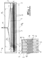
- the figures show a device 1 for producing filaments (not shown in detail) from thermoplastic material.
- the filaments are in particular continuous filaments.
- the filaments emerge from the spinneret openings 3 of a spinneret plate 2 in several rows of filaments extending over a final spinning width B e .
- the plastic melt for the filaments to be spun is first fed from an extruder (not shown in detail) via a spinning pump (also not shown in detail) to a feed channel 14.
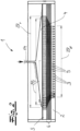
- This feed channel 14 opens into a distribution device 4, which in the embodiment according to the Figures 1 and 2 is designed as a coat hanger distributor.
- the supplied plastic melt is distributed over a preliminary spinning width B v .
- the distribution device 4 is according to the invention and in the embodiment according to the Figures 1 and 2 a filter plate 5 is connected downstream, which preferably has perforated channels 13 for the plastic melt, distributed over the preliminary spinning width B v in the exemplary embodiment.
- the filter plate 5 is recommended and used in the exemplary embodiment to support a filter 15. This is particularly important in the Figure 1
- the filter 15 is expediently and in the embodiment downstream of the distribution device 4 in the flow direction of the plastic melt.
- the filter plate 5 is again followed by a distributor plate package 6 made up of distributor plates 7.
- the distributor plate package 6 preferably has, and in the exemplary embodiment, a plurality of distributor plates 7.
- the distributor plates 7 each have a plurality of distributor openings 8 distributed over a distribution width B i , wherein the distributor openings 8 are provided for receiving the plastic melt emerging from the filter plate 5.
- B i distribution width
- the distributor openings 8 are provided for receiving the plastic melt emerging from the filter plate 5.
- a row of distributor openings 8 can be seen for each distributor plate 7, a row of distributor openings 8 can be seen.
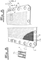
- each distribution plate 7 of the distribution plate package 6 has several rows of distribution openings 8 arranged next to one another in the direction transverse to the distribution width B i . This is the case, for example, in the Figures 3a and 3b to recognize.
- the distributor openings 8 are rectangular in cross-section according to a preferred embodiment.
- the distributor openings 8 have a round, in particular a circular, cross-section.
- the distributor openings 8 of distributor plates 7, which are arranged in the lower part of the distributor plate package 6 associated with the spinneret plate 2 have a round or circular cross-section according to the preferred embodiment.
- the distributor openings 8 of a distributor plate 7 each have the same diameter or substantially the same diameter.
- the diameter of a portion of the distributor openings 8 of at least one distributor plate 7 of the distributor plate package 6 differs from the diameter of the remaining distributor openings 8 of this distributor plate 7.
- this can be the last distributor plate 7 of the distributor plate package 6 arranged directly above the spinneret plate 2.
- the distributor openings 8 are then round, in particular circular, and the diameter of the distributor openings then means in particular the diameter of the circular distributor openings.
- CD outer region 16 of the distributor plate 7 means in particular an outer region of the distributor plate 7 extending parallel to the CD direction, i.e. along the distribution width or spinning width.
- the distributor openings 8 of the superimposed rows of adjacent superimposed distributor plates 7 are offset from one another with respect to the distribution width B i .
- the distributor plates 7 of the distributor plate package 6 preferably have distributor channels 12 extending over the spinning width B i , each distributor channel 12 connecting the distributor openings 8 of a row to one another.
- a distributor channel 12 At least in the majority of the distributor plates 7, a distributor channel 12 directly adjoins an adjacent distributor plate 7. In other words, this adjacent distributor plate 7 forms a wall of the adjacent distributor channel 12.
- This distributor channel 12 expediently connects distributor openings 8 of the adjacent distributor plate 7, which are arranged in a row in the exemplary embodiment.
- the distributor plate package 6 or the distributor plates 7 is followed by an exchangeable spinneret plate 2, which has spinneret channels 9 with the associated spinneret openings 3 distributed over the final spinning width B e .
- the Figure 4 shows a spinneret plate 2 with spinneret channels 9 or spinneret openings 3.
- a plurality of rows of spinneret channels 9 or spinneret openings 3 are arranged next to one another transversely to the final spinning width B e , in particular in the machine direction (MD).
- the distributor openings 8 together with the distributor channels 12 preferably form flow paths for the plastic melt through the distributor plate package 6.
- a flow path consisting of distributor openings 8 and distributor channels 12 is expediently assigned to each spinneret channel 9 or each spinneret opening 3 of the spinneret plate 2 and thus in particular also to each filament produced.
- an outlet surface 10 of the filter plate 5 assigned to the distributor plate package 6 and an inlet surface 11 of the spinneret plate 2 assigned to the distributor plate package 6 are curved or spherical over their entire or essentially entire extension in the machine direction (MD).
- MD machine direction
- the exit surface 10 of the filter plate 5 and the entry surface 11 of the spinneret plate 2 are curved or ground to a crown.
- machine direction also means in particular the conveying direction of a conveying device for the filaments or the nonwoven web produced therefrom and thus the direction transverse to the spinning width or distribution width.
- the curvature or crowning of the filter plate 5 or the spinneret plate 2 is thus realized over the entire extent of the outlet surface 10 of the filter plate and the inlet surface 11 of the filter plate in the machine direction (MD).
- the radius of curvature R of the curved or crowned outlet surface 10 of the filter plate 5 and the inlet surface 11 of the spinneret plate 2 is constant or essentially constant over the entire extent in the machine direction (MD).
- the radius of curvature R may be 17,000 mm to 19,000 mm.
- the distribution device 4 or the filter plate 5 is a distribution plate package 6 consisting of a plurality of exchangeable distributor plates 7.
- the distribution widths B i formed by the distributor openings 8 of the individual distributor plates 7 expediently and in the embodiment according to the Figure 1 from the filter plate 5 to the spinneret plate 2.
- the preliminary spinning width B v is thus expanded or increased to the final spinning width B e .
- the distribution width B i therefore increases from distributor plate 7 to distributor plate 7 to the spinneret plate 2.
- a distributor plate package 6 consisting of a plurality of exchangeable distributor plates 7 is also connected downstream of the distributor device 4 or the filter plate 5.
- the distribution widths B i formed by the distribution openings 8 of the individual distribution plates 7 decrease from the filter plate 5 to the spinneret plate 2.
- the preliminary spinning width B v is reduced in this way to the final spinning width B e .
- the distribution width B i therefore decreases here from distributor plate 7 to distributor plate 7 to the spinneret plate 2.
- not all distributor plates 7 of the distributor plate package 6 have distribution channels 12. According to an embodiment not shown in detail in the figures, it is possible that the lower distributor plates 7 of the distributor plate package 6, which are assigned to the spinneret plate 2, do not have distribution channels 12 and that the final distribution width B e is already reached above these distributor plates 7.
- the final spinning width B e is at least 1,600 mm, preferably at least 1,800 mm. In the embodiment according to the figures, the final spinning width may, for example, be at least 2,000 mm. It has proven useful that the ratio of the provisional spinning width B v to the final spinning width B e (B v :B e ) in the event of a reduction in the provisional spinning width is 1.02 to 1.3 and in the case of an extension of the provisional spinning width B v is 0.8 to 0.97. In the embodiment according to the Figure 1 , in which the preliminary spinning width B v is extended, the ratio B v :B e may be between 0.85 and 0.95. In the embodiment according to Figure 2 , in which the preliminary spinning width B v is reduced, the ratio B v :B e may be 1.05 to 1.15.
Landscapes
- Engineering & Computer Science (AREA)
- Textile Engineering (AREA)
- Mechanical Engineering (AREA)
- Spinning Methods And Devices For Manufacturing Artificial Fibers (AREA)
Priority Applications (17)
| Application Number | Priority Date | Filing Date | Title |
|---|---|---|---|
| EP24212727.2A EP4484623A3 (de) | 2022-12-21 | 2022-12-21 | Vorrichtung zur herstellung von filamenten |
| EP22215646.5A EP4389946B1 (de) | 2022-12-21 | 2022-12-21 | Vorrichtung zur herstellung von filamenten |
| PL22215646.5T PL4389946T3 (pl) | 2022-12-21 | 2022-12-21 | Urządzenie do wytwarzania filamentów |
| MA66080A MA66080B1 (fr) | 2022-12-21 | 2022-12-21 | Dispositif de fabrication de filaments |
| ES22215646T ES3015423T3 (en) | 2022-12-21 | 2022-12-21 | Filament production apparatus |
| JP2023201321A JP2024089635A (ja) | 2022-12-21 | 2023-11-29 | フィラメントを製造するための装置 |
| CL2023003750A CL2023003750A1 (es) | 2022-12-21 | 2023-12-14 | Aparato para la producción de filamentos |
| MX2023015476A MX2023015476A (es) | 2022-12-21 | 2023-12-15 | Dispositivo para la produccion de filamentos. |
| US18/542,841 US20240209547A1 (en) | 2022-12-21 | 2023-12-18 | Filament-making apparatus |
| KR1020230185659A KR20240099056A (ko) | 2022-12-21 | 2023-12-19 | 필라멘트 제조 장치 |
| CONC2023/0017893A CO2023017893A1 (es) | 2022-12-21 | 2023-12-19 | Aparato para la producción de filamentos |
| ZA2023/11671A ZA202311671B (en) | 2022-12-21 | 2023-12-20 | Apparatus for the production of filaments |
| ARP230103468A AR131431A1 (es) | 2022-12-21 | 2023-12-20 | Aparato para la producción de filamentos |
| IL309632A IL309632A (en) | 2022-12-21 | 2023-12-21 | Apparatus for the production of filaments |
| JOJO/P/2023/0324A JOP20230324A1 (ar) | 2022-12-21 | 2023-12-21 | جهاز لإنتاج خيوط |
| CN202311779525.5A CN118223136A (zh) | 2022-12-21 | 2023-12-21 | 用于制造长丝的设备 |
| PE2023003430A PE20241161A1 (es) | 2022-12-21 | 2023-12-21 | Aparato para la produccion de filamentos |
Applications Claiming Priority (1)
| Application Number | Priority Date | Filing Date | Title |
|---|---|---|---|
| EP22215646.5A EP4389946B1 (de) | 2022-12-21 | 2022-12-21 | Vorrichtung zur herstellung von filamenten |
Related Child Applications (2)
| Application Number | Title | Priority Date | Filing Date |
|---|---|---|---|
| EP24212727.2A Division EP4484623A3 (de) | 2022-12-21 | 2022-12-21 | Vorrichtung zur herstellung von filamenten |
| EP24212727.2A Division-Into EP4484623A3 (de) | 2022-12-21 | 2022-12-21 | Vorrichtung zur herstellung von filamenten |
Publications (3)
| Publication Number | Publication Date |
|---|---|
| EP4389946A1 EP4389946A1 (de) | 2024-06-26 |
| EP4389946C0 EP4389946C0 (de) | 2025-02-12 |
| EP4389946B1 true EP4389946B1 (de) | 2025-02-12 |
Family
ID=84569167
Family Applications (2)
| Application Number | Title | Priority Date | Filing Date |
|---|---|---|---|
| EP22215646.5A Active EP4389946B1 (de) | 2022-12-21 | 2022-12-21 | Vorrichtung zur herstellung von filamenten |
| EP24212727.2A Pending EP4484623A3 (de) | 2022-12-21 | 2022-12-21 | Vorrichtung zur herstellung von filamenten |
Family Applications After (1)
| Application Number | Title | Priority Date | Filing Date |
|---|---|---|---|
| EP24212727.2A Pending EP4484623A3 (de) | 2022-12-21 | 2022-12-21 | Vorrichtung zur herstellung von filamenten |
Country Status (5)
| Country | Link |
|---|---|
| EP (2) | EP4389946B1 (pl) |
| CN (1) | CN118223136A (pl) |
| ES (1) | ES3015423T3 (pl) |
| MA (1) | MA66080B1 (pl) |
| PL (1) | PL4389946T3 (pl) |
Family Cites Families (3)
| Publication number | Priority date | Publication date | Assignee | Title |
|---|---|---|---|---|
| US3460199A (en) * | 1967-08-11 | 1969-08-12 | Du Pont | Spinneret assembly |
| DE4419555C1 (de) * | 1994-06-03 | 1995-09-28 | Rieter Automatik Gmbh | Stranggießer für Stranggießanlagen, insbesondere für thermoplastische Kunststoffe |
| EP1486591B1 (de) | 2003-06-13 | 2005-11-16 | Reifenhäuser GmbH & Co. KG Maschinenfabrik | Vorrichtung zur Herstellung von Filamenten |
-
2022
- 2022-12-21 PL PL22215646.5T patent/PL4389946T3/pl unknown
- 2022-12-21 EP EP22215646.5A patent/EP4389946B1/de active Active
- 2022-12-21 MA MA66080A patent/MA66080B1/fr unknown
- 2022-12-21 EP EP24212727.2A patent/EP4484623A3/de active Pending
- 2022-12-21 ES ES22215646T patent/ES3015423T3/es active Active
-
2023
- 2023-12-21 CN CN202311779525.5A patent/CN118223136A/zh active Pending
Also Published As
| Publication number | Publication date |
|---|---|
| MA66080B1 (fr) | 2025-03-28 |
| PL4389946T3 (pl) | 2025-06-09 |
| EP4389946A1 (de) | 2024-06-26 |
| EP4484623A3 (de) | 2025-02-12 |
| ES3015423T3 (en) | 2025-05-05 |
| CN118223136A (zh) | 2024-06-21 |
| EP4389946C0 (de) | 2025-02-12 |
| EP4484623A2 (de) | 2025-01-01 |
Similar Documents
| Publication | Publication Date | Title |
|---|---|---|
| DE69425537T2 (de) | Schmelzblasdüse | |
| DE60309653T2 (de) | Vorrichtung zur herstellung von thermoplastischen vliesstoffen und verbundstoffen | |
| EP1902164B1 (de) | Spinnvorrichtung und verfahren zur erzeugung feiner fäden durch spleissen zwecks bildung eines spinnvlieses, sowie das dadurch erhaltene spinnvlies | |
| EP2016210B1 (de) | Vorrichtung zum schmelzspinnen einer reihenförmigen filamentschar | |
| EP1192301B1 (de) | Verfahren und vorrichtung zur herstellung von im wesentlichen endlosen feinen fäden | |
| EP3692188B1 (de) | Vorrichtung für die extrusion von filamenten und herstellung von spinnvliesstoffen | |
| DE4040242A1 (de) | Verfahren und vorrichtung zur herstellung von feinstfasern aus thermoplastischen polymeren | |
| EP3382081B1 (de) | Vorrichtung zur herstellung von spinnvliesen aus endlosfilamenten | |
| EP2663673B1 (de) | Spinndüsenpaket | |
| EP3575469B1 (de) | Vorrichtung und verfahren zur herstellung von spinnvliesen aus endlosfilamenten | |
| EP1486591B1 (de) | Vorrichtung zur Herstellung von Filamenten | |
| WO2009112082A1 (de) | Vorrichtung zum schmelzspinnen von mehrkomponentenfasern | |
| DE112005003176B4 (de) | Vorrichtung zum Bilden von Schmelzblasmaterial | |
| EP1512777B1 (de) | Vorrichtung zur Erzeugung von Mehrkomponentenfasern, insbesondere von Bikomponentenfasern | |
| DE69201176T2 (de) | Verfahren und Vorrichtung zum Abkühlen von Fasern. | |
| EP4123063B1 (de) | Düsenkopf zur erzeugung von filamenten | |
| EP0455897A1 (de) | Vorrichtung zum Herstellen von Feinstfäden | |
| EP2135980B1 (de) | Vorrichtung zum Abziehen von Filamenten | |
| DE69611346T2 (de) | Verfahren und Vorrichtung zur Herstellung von Bikomponentenfasern | |
| EP4389946B1 (de) | Vorrichtung zur herstellung von filamenten | |
| DE102022134399A1 (de) | Vorrichtung zur Herstellung von Filamenten | |
| DE102013010120A1 (de) | Spinndüsenvorrichtung | |
| EP1729900B1 (de) | Vorrichtung zum kühlen von blechen und bändern | |
| DE102004038462A1 (de) | Spinnkopf | |
| DE69713791T2 (de) | Kegelnase für einen kleinen spinnkopf zum flash-spinnen |
Legal Events
| Date | Code | Title | Description |
|---|---|---|---|
| PUAI | Public reference made under article 153(3) epc to a published international application that has entered the european phase |
Free format text: ORIGINAL CODE: 0009012 |
|
| STAA | Information on the status of an ep patent application or granted ep patent |
Free format text: STATUS: REQUEST FOR EXAMINATION WAS MADE |
|
| 17P | Request for examination filed |
Effective date: 20231026 |
|
| AK | Designated contracting states |
Kind code of ref document: A1 Designated state(s): AL AT BE BG CH CY CZ DE DK EE ES FI FR GB GR HR HU IE IS IT LI LT LU LV MC ME MK MT NL NO PL PT RO RS SE SI SK SM TR |
|
| REG | Reference to a national code |
Ref country code: DE Ref legal event code: R079 Free format text: PREVIOUS MAIN CLASS: D01D0004020000 Ipc: D01D0005098000 Ref country code: DE Ref legal event code: R079 Ref document number: 502022002870 Country of ref document: DE Free format text: PREVIOUS MAIN CLASS: D01D0004020000 Ipc: D01D0005098000 |
|
| GRAP | Despatch of communication of intention to grant a patent |
Free format text: ORIGINAL CODE: EPIDOSNIGR1 |
|
| STAA | Information on the status of an ep patent application or granted ep patent |
Free format text: STATUS: GRANT OF PATENT IS INTENDED |
|
| RIC1 | Information provided on ipc code assigned before grant |
Ipc: D01D 5/30 20060101ALI20241008BHEP Ipc: D01D 4/00 20060101ALI20241008BHEP Ipc: D01D 1/10 20060101ALI20241008BHEP Ipc: D01D 4/08 20060101ALI20241008BHEP Ipc: D04H 3/16 20060101ALI20241008BHEP Ipc: D01D 4/06 20060101ALI20241008BHEP Ipc: D01D 4/02 20060101ALI20241008BHEP Ipc: D01D 5/098 20060101AFI20241008BHEP |
|
| INTG | Intention to grant announced |
Effective date: 20241022 |
|
| GRAS | Grant fee paid |
Free format text: ORIGINAL CODE: EPIDOSNIGR3 |
|
| GRAA | (expected) grant |
Free format text: ORIGINAL CODE: 0009210 |
|
| STAA | Information on the status of an ep patent application or granted ep patent |
Free format text: STATUS: THE PATENT HAS BEEN GRANTED |
|
| AK | Designated contracting states |
Kind code of ref document: B1 Designated state(s): AL AT BE BG CH CY CZ DE DK EE ES FI FR GB GR HR HU IE IS IT LI LT LU LV MC ME MK MT NL NO PL PT RO RS SE SI SK SM TR |
|
| REG | Reference to a national code |
Ref country code: GB Ref legal event code: FG4D Free format text: NOT ENGLISH |
|
| REG | Reference to a national code |
Ref country code: CH Ref legal event code: EP |
|
| REG | Reference to a national code |
Ref country code: DE Ref legal event code: R096 Ref document number: 502022002870 Country of ref document: DE |
|
| REG | Reference to a national code |
Ref country code: IE Ref legal event code: FG4D Free format text: LANGUAGE OF EP DOCUMENT: GERMAN |
|
| REG | Reference to a national code |
Ref country code: MA Ref legal event code: VAGR Ref document number: 66080 Country of ref document: MA Kind code of ref document: B1 |
|
| U01 | Request for unitary effect filed |
Effective date: 20250304 |
|
| U07 | Unitary effect registered |
Designated state(s): AT BE BG DE DK EE FI FR IT LT LU LV MT NL PT RO SE SI Effective date: 20250312 |
|
| REG | Reference to a national code |
Ref country code: GR Ref legal event code: EP Ref document number: 20250400622 Country of ref document: GR Effective date: 20250514 |
|
| PG25 | Lapsed in a contracting state [announced via postgrant information from national office to epo] |
Ref country code: RS Free format text: LAPSE BECAUSE OF FAILURE TO SUBMIT A TRANSLATION OF THE DESCRIPTION OR TO PAY THE FEE WITHIN THE PRESCRIBED TIME-LIMIT Effective date: 20250512 |
|
| PG25 | Lapsed in a contracting state [announced via postgrant information from national office to epo] |
Ref country code: IS Free format text: LAPSE BECAUSE OF FAILURE TO SUBMIT A TRANSLATION OF THE DESCRIPTION OR TO PAY THE FEE WITHIN THE PRESCRIBED TIME-LIMIT Effective date: 20250612 Ref country code: NO Free format text: LAPSE BECAUSE OF FAILURE TO SUBMIT A TRANSLATION OF THE DESCRIPTION OR TO PAY THE FEE WITHIN THE PRESCRIBED TIME-LIMIT Effective date: 20250512 |
|
| PG25 | Lapsed in a contracting state [announced via postgrant information from national office to epo] |
Ref country code: HR Free format text: LAPSE BECAUSE OF FAILURE TO SUBMIT A TRANSLATION OF THE DESCRIPTION OR TO PAY THE FEE WITHIN THE PRESCRIBED TIME-LIMIT Effective date: 20250212 |
|
| PG25 | Lapsed in a contracting state [announced via postgrant information from national office to epo] |
Ref country code: SM Free format text: LAPSE BECAUSE OF FAILURE TO SUBMIT A TRANSLATION OF THE DESCRIPTION OR TO PAY THE FEE WITHIN THE PRESCRIBED TIME-LIMIT Effective date: 20250212 |
|
| PG25 | Lapsed in a contracting state [announced via postgrant information from national office to epo] |
Ref country code: SK Free format text: LAPSE BECAUSE OF FAILURE TO SUBMIT A TRANSLATION OF THE DESCRIPTION OR TO PAY THE FEE WITHIN THE PRESCRIBED TIME-LIMIT Effective date: 20250212 |
|
| PLBE | No opposition filed within time limit |
Free format text: ORIGINAL CODE: 0009261 |
|
| STAA | Information on the status of an ep patent application or granted ep patent |
Free format text: STATUS: NO OPPOSITION FILED WITHIN TIME LIMIT |
|
| REG | Reference to a national code |
Ref country code: CH Ref legal event code: L10 Free format text: ST27 STATUS EVENT CODE: U-0-0-L10-L00 (AS PROVIDED BY THE NATIONAL OFFICE) Effective date: 20251224 |
|
| REG | Reference to a national code |
Ref country code: CH Ref legal event code: U11 Free format text: ST27 STATUS EVENT CODE: U-0-0-U10-U11 (AS PROVIDED BY THE NATIONAL OFFICE) Effective date: 20260101 |
|
| PGFP | Annual fee paid to national office [announced via postgrant information from national office to epo] |
Ref country code: TR Payment date: 20251215 Year of fee payment: 4 Ref country code: GR Payment date: 20251222 Year of fee payment: 4 |
|
| PGFP | Annual fee paid to national office [announced via postgrant information from national office to epo] |
Ref country code: CZ Payment date: 20251126 Year of fee payment: 4 |
|
| 26N | No opposition filed |
Effective date: 20251113 |
|
| PGFP | Annual fee paid to national office [announced via postgrant information from national office to epo] |
Ref country code: PL Payment date: 20251124 Year of fee payment: 4 |
|
| U20 | Renewal fee for the european patent with unitary effect paid |
Year of fee payment: 4 Effective date: 20251220 |
|
| VSFP | Annual fee paid to validation state [announced via postgrant information from national office to epo] |
Ref country code: MA Payment date: 20251226 Year of fee payment: 4 |