EP4389552B1 - Système de transport par câble aérien et procédé de fonctionnement d'un tel système - Google Patents
Système de transport par câble aérien et procédé de fonctionnement d'un tel système Download PDFInfo
- Publication number
- EP4389552B1 EP4389552B1 EP23219121.3A EP23219121A EP4389552B1 EP 4389552 B1 EP4389552 B1 EP 4389552B1 EP 23219121 A EP23219121 A EP 23219121A EP 4389552 B1 EP4389552 B1 EP 4389552B1
- Authority
- EP
- European Patent Office
- Prior art keywords
- cable
- vehicles
- supporting
- storage
- transport
- Prior art date
- Legal status (The legal status is an assumption and is not a legal conclusion. Google has not performed a legal analysis and makes no representation as to the accuracy of the status listed.)
- Active
Links
Images


Classifications
-
- B—PERFORMING OPERATIONS; TRANSPORTING
- B61—RAILWAYS
- B61B—RAILWAY SYSTEMS; EQUIPMENT THEREFOR NOT OTHERWISE PROVIDED FOR
- B61B7/00—Rope railway systems with suspended flexible tracks
- B61B7/02—Rope railway systems with suspended flexible tracks with separate haulage cables
-
- B—PERFORMING OPERATIONS; TRANSPORTING
- B61—RAILWAYS
- B61B—RAILWAY SYSTEMS; EQUIPMENT THEREFOR NOT OTHERWISE PROVIDED FOR
- B61B12/00—Component parts, details or accessories not provided for in groups B61B7/00 - B61B11/00
- B61B12/02—Suspension of the load; Guiding means, e.g. wheels; Attaching traction cables
- B61B12/026—Guiding means for deflecting the direction of the cables between the stations
-
- B—PERFORMING OPERATIONS; TRANSPORTING
- B61—RAILWAYS
- B61B—RAILWAY SYSTEMS; EQUIPMENT THEREFOR NOT OTHERWISE PROVIDED FOR
- B61B12/00—Component parts, details or accessories not provided for in groups B61B7/00 - B61B11/00
- B61B12/02—Suspension of the load; Guiding means, e.g. wheels; Attaching traction cables
- B61B12/028—Cabin or seat suspension means
Definitions
- the reference technical field of this invention relates to the aerial cable transporting system sector. These systems provide multiple transport units for transporting passengers or goods, which are moved, one after the other, in aerial mode along a predefined course by at least one cable. For the purposes of this invention, the forward movement of the transport units along the at least one supporting cable is generated by a hauling cable.
- the reference technical field of this invention relates to aerial cable transporting systems wherein there is a hauling cable and at least one supporting cable.
- the present invention will deal with the issue of how to support, understood as maintain in a particular position, the hauling cable during the steps wherein the transport units are stored, for example during the system's stop or during maintenance and inspection wherein the hauling cable is moving without there being vehicles on the line.
- Aerial cable transporting systems are widespread today and, thus, are in general well known to a skill person operating in this particular technical sector.
- the passengers, or the goods are transported along a course in special transport units, for example cabins, chairs, or something else, which will be called “vehicles", for simplicity, below.
- the path is delimited at the opposite ends by two terminal stations for embarking and disembarking and the vehicles are fed in an aerial configuration one after the other along a first branch from the first station to the second and along a second branch (usually parallel to the first) from the second station to the first.
- the term "aerial” refers to cable systems in which the vehicles are moved along at least one supporting cable in a position raised above the underlying ground (i.e., in aerial mode).
- This invention preferably relates to aerial transport systems with one or with two supporting cables per transport branch.
- the movement of the vehicles between the stations along the at least one supporting cable is generated by a hauling cable to which all the units are selectively coupled or clamped when they travel from one station to another.
- the vehicles are unhooked from the hauling cable so that they can move forward more slowly in relation to the vehicles moving outside the stations.
- the hauling cable is arranged in a ring in the terminal stations, which, to this end, house special pulleys, including at least one motorised one, while the at least one supporting cable is basically fixed with ends attached in the terminal stations.
- the at least one supporting cable is, in fact, only moved between the stations during maintenance.
- every vehicle is equipped with a trolley with rollers that roll on the at least one supporting cable and a clamp (or equivalent devices) for selectively coupling to the hauling cable.
- Each fixed intermediate support structure for the supporting cable usually comprises a vertical supporting structure, such as a pylon or a tower, on top of which there are support devices for the supporting cable, known as "shoes".
- the shoe comprises a basically "U"-shaped seat for the supporting cable.
- the hauling cable if included, is instead supported by a series of rollers arranged below the seat of the supporting cable.
- the fact that the hauling cable is not subject to strong tension is not a problem.
- the hauling cable is in fact supported in its operating position by the clamp of the vehicles that, in turn, are supported in position by the at least one supporting cable.
- the hauling cable does not give downwards but remains raised in the correct operating position due to the presence of vehicles moving along the at least one supporting cable.
- US6363859B1 shows cabins for cable systems, in particular for systems with two cables, wherein the cabins are equipped with devices for automatically locking to the cable.
- the starting point for this invention is to provide an aerial cable transporting system of the type comprising:
- the hauling cable is preferably moved by a motorised pulley housed within one of the stations.
- the vehicles are not coupled to the hauling cable (nor supported by the at least one supporting cable) so that they can advance more slowly than the vehicles that travel between the stations.
- each vehicle is preferably equipped with a clamp (or equivalent device) that entering and leaving the station is respectively opened and closed (automatically, as known, with sprung levers that act against fixed abutments in the station) to selectively release and couple with the hauling cable.
- This clamp is well known to the person skilled in the art and, thus, other details are not necessary.
- the way the vehicles are moved inside the station is also known.
- each vehicle is equipped with a trolley with rollers configured to roll on the at least one supporting cable between the stations and on the dedicated tracks in the station.
- these fixed supports are no longer necessary and, in general (even for systems with just one supporting cable per branch), they have been replaced with innovative support devices configured to support the hauling cable when the system is stopped when these support devices are not fixed but mobile along the at least one supporting cable.
- the term "to support” means what is described above, i.e., keeping the hauling cable in a suitably raised position so as to avoid the problems mentioned and that basically corresponds to the position that it assumes when the system is being used, when it is, in fact, kept raised by the clamps of the vehicles that travel along the two transport branches defined by the at least one supporting cable.
- These mobile support devices for the hauling cable are housed in a storage when the system is being used (preferably the same storage described above that accommodates the vehicles during stoppage) and are fed along the supporting cables when the vehicles return to the storage so that, when all the vehicles are stored, all the mobile support devices have reached their operating position along the branches.
- the hauling cable gradually changes from being supported by the vehicles to the mobile support devices.
- the mobile support devices When all the vehicles are stored, the mobile support devices have reached their operating position and the hauling cable can be stopped, thus stopping the system. In this position, with a stopped hauling cable, the mobile devices will support the hauling cable until the next phase of using the system, wherein the mobile support devices gradually restart along the branches of the supporting cables to reach the storage and the vehicles are reintroduced to the transport branches. In this way, the hauling cable gradually changes from being supported by the mobile support devices to the vehicles.
- every mobile support device comprises a trolley provided with rollers for rolling on the at least one supporting cable.
- the trolley of the mobile support device is of exactly the same type as the trolleys that enable the vehicles to advance along the at least one supporting cable and on the station tracks. If there is just one supporting cable, the rollers are arranged in a single row; if there are two supporting cables, the rollers are arranged in two corresponding rows.
- Each mobile support device preferably comprises a clamp for selectively coupling to the hauling cable in which this clamp is exactly the same type present on the vehicles for their selective coupling to the hauling cable exiting and entering the stations.
- each mobile support device may comprise a counterweight configured to bring the mobile device's centre of mass below the supporting cable.
- the counterweight may, preferably, be provided at the end of a support arm that extends downwards from the trolley. This arm may, preferably, be exactly the type that connects the cabins of the vehicles to the corresponding trolley.
- each mobile support device corresponds to the vehicle of the system in which the transport unit was removed (seat or cabin or other) and, thus, the components that are the same used both for the vehicles and for the mobile support devices are strongly optimised.
- this invention would be adapted according to a method in which to bring the cabins with passengers to stop, they are called to the station to empty the system and after (or gradually with the emptying) some empty vehicles (for example one in every four) are introduced on the line to act as a support device for the hauling cable as described above.
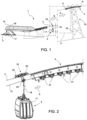
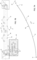
- Figure 1 schematically shows a portion of an aerial cable transportation system globally denoted with the reference number 1 and that can be improved thanks to this invention.
- the aerial cable system 1 comprises cables (indicated in Figure 1 , in general, with the reference number 2) and a first terminal station 14, for embarking and disembarking passengers, can be seen.
- This example comprises two parallel transport branches that define an ascent branch 30 and a descent branch 31 of the system.
- the arrows A and B in Figure 1 indicate the advancing directions of the ascent 30 and descent 31 branches.
- Figure 1 represents one of the multiple vehicles 3 present in the system that run, one after the other, along both the ascent and descent branches.
- a first vehicle 3 is located at the station 14 inside of which it is detached from the cables 2.
- the second vehicle 3 shown in Figure 1 is running along the ascent branch and is arranged between the station 14 and a first fixed intermediate support structure 15 in the form of a pylon 16.
- the function of the pylons 16 arranged between the stations is to divide the cables into separate bays.
- each vehicle 3 comprises a cabin 17, a trolley 19 coupled to the cables 2, and a suspension arm 18 that connects the cabin 17 to the trolley 19.
- a shoe assembly 4 for supporting the cables 2 with an inlet portion 5 and an outlet portion 6.
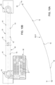
- Figure 2 shows the enlarged view of the portion identified with the reference II in Figure 1 .
- the system 1 comprises a supporting cable 2 and a hauling cable 13.
- the system could also comprise two supporting cables.
- Figure 2 shows a trolley 19 provided with rollers 20 for rolling on the supporting cable 2.
- the reference number 25 indicates the clamp for selectively coupling the hauling cable 13.
- the inlet and outlet portions of the station comprise devices that act against the clamp to open it at the inlet, so as to detach the vehicle 3 form the hauling cable 13, and to close it at the outlet, so as to attach the vehicle 3 by the hauling cable 13.
- the shoe 4 is only partially visible in Figure 2 .
- the supporting cable 2 is housed in special U-shaped seats on the upper end of the shoe 4 while the hauling cable 13 is housed along a series of rollers 21 placed lower down.
- the clamp locally raises the hauling cable. So as not to have to stretch the hauling cable excessively, it is necessary to equip the system with devices that are able to support the hauling cable, i.e., keep it raised when the system is stopped when, in the absence of vehicles 3, the cable 13 would assume a position too low down compared to the supporting cable/s.
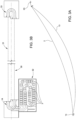
- Figures 3a and 3b show precisely this situation to avoid in which all the vehicles 3 are stored 32 and there are no devices able to keep the cable 13 basically in line with the supporting cable 2 as, instead, occurs when the system is used due to the presence of the vehicles 3 along the branches.
- the reference number 33 indicates the second terminal station.
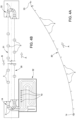
- Figures 4a and 4b show precisely that situation that represents the starting point to describe the innovative support devices 10 of the hauling cable that, according to this invention, are mobile along the supporting cable 2. In Figures 4a and 4b , you can see how, when the system is being used, the mobile support devices 10 are placed in storage 32 where it is possible to easily do maintenance.
- the vehicles 3 that transit in the station 14 are diverted (in a known way) and gradually sent to the storage 32.
- a "hole" is thus created in the first section of the ascent branch 30 as can be seen in Figures 5a and 5b .
- Figures 6A and 6B show the subsequent steps wherein more and more vehicles 3 are diverted to the storage 32.
- the absence of these vehicles 3 along the branch 30 would lead to there being a bigger and bigger hole for supporting the hauling cable 13 that, instead, according to this invention is filled by feeding the first mobile support devices 10, which replace the vehicles 3 in their function of supporting the hauling cable, in the ascent branch 30.
- the number of devices 10 needed for example, it is possible to include one device 10 for every four vehicles.
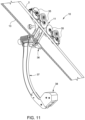
- FIG. 11 One example of how these mobile support devices 10 are supported by the supporting cable 2 and how they are coupled to the hauling cable 13 will be shown in Figure 11 .
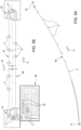
- Figures 7a and 7b show subsequent steps in which no vehicle 3 is present on the ascent branch 30 and the hauling cable 13 inevitably does not droop down, as can be seen in Figure 3A , but remains raised thanks to mobile support devices 10 that run and are present along the ascent branch 30.
- the section of hauling cable 13 of the descent branch 31 is still supported by the vehicles 3.
- Figures 8a , 9a , 8b , and 9b show subsequent steps in which the few vehicles 3 not in storage 32 are arriving in the station 14 at the end of the descent branch 31 and the support devices 10 have started working in this descent branch 31.
- Figures 10a and 10b show the final step of this process wherein the hauling cable 13 can be stopped.
- all the vehicles 3 are in storage 32 and all the support devices 10 are in their operating position in which they will remain until the system starts up again. At start up, it will be enough to drive the hauling cable 13 that will gradually make the support devices 10 arrive in the station 14 where they will be diverted towards the storage 32.
- the vehicles 3 will be gradually sent by the storage 32 to the station 14 and, from there, along the branch 30 of the system. At the end of transit, it will be returned to the configuration in Figures 4a and 4b with the vehicles 3 moving along both branches 30 and 31.
- FIG 11 shows a construction example of a mobile support device 10 according to this invention.
- a system with a supporting cable 2 is shown and the support device 10 comprises a trolley 11 with rollers 35 for rolling on the supporting cable 2, a clamp 36 for selective coupling to the hauling cable 13, a suspension arm 37 on one side coupled to the trolley 11 and on the other side provided with a counterweight 38 for bringing the centre of mass of the device 10 in line below the supporting cable 2.
- the device 10 is thus wholly similar to the suspension of the vehicles 3 that circulate in the same system ( Figure 2 ) i.e., there is the same clamp 36 (thus, the coupling and release at the outlet and inlet of the station is performed without problems), the same trolley 11, and the same suspension arm 37.
- the mobile support device 10 corresponds to a vehicle 3 from which the transport unit is removed and to which the counterweight 38 is coupled. Even the drive levers of the clamp 36 are, thus, the same included in the system vehicles.
- the trolley of the device 10 may be a trolley known to the person skilled in the art and used to make the vehicles advance in systems of this type.
Landscapes
- Engineering & Computer Science (AREA)
- Transportation (AREA)
- Mechanical Engineering (AREA)
- Warehouses Or Storage Devices (AREA)
- Unwinding Of Filamentary Materials (AREA)
- Electric Cable Installation (AREA)
Claims (10)
- Système de transport par câble aérien (1) pour le transport de passagers et/ou de marchandises, le système comprenant :- une première station terminale (14) et une deuxième station terminale (33) ;- un câble de traction (13) disposé en anneau entre les stations (14, 33) pour créer deux branches (30, 31) de directions de transport opposées ;- au moins un câble de support (2) pour chaque branche de transport (30, 31) entre les stations (14, 33) ;- une pluralité de véhicules (3) de transport de passagers et/ou de marchandises configurés pour circuler le long des branches de transport (30, 31) dans une configuration aérienne entre les stations (14, 33), supportés par le ou les câbles de support (2) et tractés par le câble de traction (13) ;- une pluralité de dispositifs de support (10) configurés pour supporter le câble de traction (13) pendant l'arrêt du système lorsque les véhicules (3) ne circulent pas le long des branches de transport (30, 31) ;caractérisé par le fait que :- un stockage (32) est prévu pour stocker sélectivement les dispositifs de support (10) pendant l'utilisation du système et les véhicules (3) pendant l'arrêt du système ;- les dispositifs de support (10) sont mobiles le long des branches de transport (30, 31) entre les stations (14, 33), supportés par au moins un câble de support (2).
- Système selon la revendication 1, dans lequel des dispositifs de déplacement vers et depuis le stockage (32) sont fournis pour stocker sélectivement des véhicules (3) et des dispositifs de support (10) d'une station (14) vers le stockage (32) et pour transférer du stockage (32) vers la station (14) des véhicules (3) et des dispositifs de support (10).
- Système selon l'une quelconque des revendications précédentes, dans lequel chaque dispositif de support (10) comprend une pince (36) configurée pour être accouplée au câble de traction (13) entre les stations (14, 33).
- Système selon la revendication 3, dans lequel chaque véhicule (3) comprend une pince (25) configurée pour s'accoupler au câble de traction (13) entre les stations (14, 33) ; les pinces des véhicules (25) et les pinces (36) des dispositifs de support (10) étant du même type.
- Système selon l'une quelconque des revendications précédentes, dans lequel chaque dispositif de support (10) comprend un chariot (11) comportant des rouleaux (35) destinés à rouler sur le ou les câbles de support (2).
- Système selon la revendication 5, dans lequel chaque véhicule (3) comprend un chariot (19) équipé de rouleaux (20) pour rouler sur le ou les câbles de support (2) ; les chariots (19) des véhicules (3) et les chariots (11) des dispositifs de support (10) étant du même type.
- Système selon l'une quelconque des revendications précédentes, dans lequel chaque dispositif de support (10) comprend un contrepoids (38).
- Système selon la revendication 7, dans lequel chaque dispositif de support (10) comprend un bras de suspension (37) qui s'étend vers le bas depuis le chariot (11) ; le contrepoids (38) étant accouplé à l'extrémité inférieure du bras de suspension (37).
- Système selon la revendication 8, dans lequel chaque véhicule (3) comprend une unité de transport (17) et un bras de suspension (18) qui relie une unité de transport (17) au chariot (19) ; les bras de suspension (18) des véhicules (3) et les bras de suspension (37) des dispositifs de support (10) étant du même type.
- Procédé d'exploitation d'un système de transport par câble aérien pour le transport de passagers et/ou de marchandises ; le procédé comprenant les étapes de :(a) fourniture d'un système (1) selon la revendication 1 ;dans lequel, pour passer de la configuration d'utilisation du système, dans laquelle les véhicules (3) circulent le long des branches de transport (30, 31) dans une configuration aérienne entre les stations (14, 33) supportés par le ou les câbles de support (2) et tractés par le câble de traction (13), à la configuration d'arrêt du système, dans laquelle les véhicules (3) sont stockés dans un stockage (32), le procédé comprend l'étape de :(b) stockage progressif des véhicules (3) dans le stockage (32) et parallèlement, introduction progressive le long des branches de transport (30, 31) des dispositifs de support (10) jusqu'à ce que tous les véhicules soient dans le stockage (32) et que tous les dispositifs de support (10) soient en place le long des branches (30, 31) et que le câble de traction (13) soit arrêté ;dans lequel, pour passer de la configuration d'arrêt du système, dans laquelle les véhicules (3) sont stockés dans le stockage (32), à la configuration d'utilisation du système, dans laquelle les véhicules (3) circulent le long des branches de transport (30, 31) dans une configuration aérienne entre des stations (14, 31), supportées par au moins un câble de support (2) et tractées par le câble de traction (13), le procédé comprenant l'étape de :
(c) stockage progressif par activation par le câble de traction (13) de tous les dispositifs de support (10) dans le stockage (32) et parallèlement, introduction progressive des véhicules (3) le long des branches de transport (30, 31) depuis le stockage (32).
Applications Claiming Priority (1)
| Application Number | Priority Date | Filing Date | Title |
|---|---|---|---|
| IT102022000026529A IT202200026529A1 (it) | 2022-12-22 | 2022-12-22 | Impianto aereo di trasporto a fune e metodo di funzionamento di tale impianto |
Publications (2)
| Publication Number | Publication Date |
|---|---|
| EP4389552A1 EP4389552A1 (fr) | 2024-06-26 |
| EP4389552B1 true EP4389552B1 (fr) | 2025-06-25 |
Family
ID=85556803
Family Applications (1)
| Application Number | Title | Priority Date | Filing Date |
|---|---|---|---|
| EP23219121.3A Active EP4389552B1 (fr) | 2022-12-22 | 2023-12-21 | Système de transport par câble aérien et procédé de fonctionnement d'un tel système |
Country Status (2)
| Country | Link |
|---|---|
| EP (1) | EP4389552B1 (fr) |
| IT (1) | IT202200026529A1 (fr) |
Family Cites Families (2)
| Publication number | Priority date | Publication date | Assignee | Title |
|---|---|---|---|---|
| FR850929A (fr) * | 1938-09-06 | 1939-12-29 | Perfectionnements aux téléfériques, notamment aux téléfériques à voyageurs | |
| IT1317222B1 (it) * | 2000-04-12 | 2003-05-27 | Leitner Spa | Dispositivo di serraggio automatico per impianti funiviari di tipobifune |
-
2022
- 2022-12-22 IT IT102022000026529A patent/IT202200026529A1/it unknown
-
2023
- 2023-12-21 EP EP23219121.3A patent/EP4389552B1/fr active Active
Also Published As
| Publication number | Publication date |
|---|---|
| EP4389552A1 (fr) | 2024-06-26 |
| IT202200026529A1 (it) | 2024-06-22 |
Similar Documents
| Publication | Publication Date | Title |
|---|---|---|
| CN111469865B (zh) | 缆索运送系统 | |
| US9193360B2 (en) | Station for a cable railway system | |
| US20080152467A1 (en) | Cableway Installation with a Garage for Transportation Devices | |
| JPH02193759A (ja) | ケーブル搬送装置 | |
| CN108137063B (zh) | 缆索运输设施 | |
| US20250100590A1 (en) | Cable car vertical loop transport system | |
| WO2006002879A1 (fr) | Dispositif convoyeur pour le transport de marchandises sur des palettes le long d'une voie de transport horizontale | |
| JPS61291264A (ja) | ロ−プウエイ搬送装置 | |
| US11220277B2 (en) | Cable transportation system | |
| EP4389552B1 (fr) | Système de transport par câble aérien et procédé de fonctionnement d'un tel système | |
| EP4122789B1 (fr) | Dispositif de batterie à rouleaux destiné à supporter un câble tracteur d'un système de transport par câble aérien et système de transport par câble aérien comprenant au moins un tel dispositif de batterie à rouleaux | |
| JP2021017238A (ja) | 2つのケーブルループ間にリレー構造体を備えるテルハ運搬装置 | |
| JPH02503901A (ja) | 垂直面内に配置された曳索及び支柱部では上記曳索から離脱するが上記曳索に係合する支持滑車を有する搬送ユニットを有するロープウエイ | |
| EP4458639B1 (fr) | Système de transport par câble aérien avec un câble de halage, deux câbles de support et au moins un dispositif de support de câble aérien pour supporter le câble de halage | |
| CN108290581B (zh) | 空中运输装备 | |
| EP4467412A1 (fr) | Installation autonome de transport de véhicules par un câble à mouvement continu | |
| EP3860735B1 (fr) | Systèmes et procédés d'évacuation de manège | |
| US6513440B1 (en) | Inclined cable car station | |
| KR100310983B1 (ko) | 장대레일 화하방법과 그 설비 | |
| US20240294361A1 (en) | Construction arrangement of an elevator and method for constructing an elevator | |
| EP4282729A1 (fr) | Ensemble de chaussure pour supporter au moins un câble porteur d'un système de transport par câble aérien | |
| EP4461617A1 (fr) | Système de transport de marchandises ou de passagers avec transfert d'unités de transport d'une configuration de transport aérien à une configuration de transport terrestre | |
| SU1146273A1 (ru) | Подъемник | |
| JPH09150733A (ja) | 索道における搬器入出庫システム | |
| KR20250152006A (ko) | 공중 케이블 운송 스테이션, 하나의 그러한 스테이션을 포함하는 공중 케이블 운송 설비 및 하나의 그러한 설비의 작동 방법 |
Legal Events
| Date | Code | Title | Description |
|---|---|---|---|
| PUAI | Public reference made under article 153(3) epc to a published international application that has entered the european phase |
Free format text: ORIGINAL CODE: 0009012 |
|
| STAA | Information on the status of an ep patent application or granted ep patent |
Free format text: STATUS: THE APPLICATION HAS BEEN PUBLISHED |
|
| AK | Designated contracting states |
Kind code of ref document: A1 Designated state(s): AL AT BE BG CH CY CZ DE DK EE ES FI FR GB GR HR HU IE IS IT LI LT LU LV MC ME MK MT NL NO PL PT RO RS SE SI SK SM TR |
|
| STAA | Information on the status of an ep patent application or granted ep patent |
Free format text: STATUS: REQUEST FOR EXAMINATION WAS MADE |
|
| 17P | Request for examination filed |
Effective date: 20240917 |
|
| RBV | Designated contracting states (corrected) |
Designated state(s): AL AT BE BG CH CY CZ DE DK EE ES FI FR GB GR HR HU IE IS IT LI LT LU LV MC ME MK MT NL NO PL PT RO RS SE SI SK SM TR |
|
| GRAP | Despatch of communication of intention to grant a patent |
Free format text: ORIGINAL CODE: EPIDOSNIGR1 |
|
| STAA | Information on the status of an ep patent application or granted ep patent |
Free format text: STATUS: GRANT OF PATENT IS INTENDED |
|
| RIC1 | Information provided on ipc code assigned before grant |
Ipc: B61B 12/02 20060101ALI20250107BHEP Ipc: B61B 7/02 20060101AFI20250107BHEP |
|
| INTG | Intention to grant announced |
Effective date: 20250121 |
|
| GRAS | Grant fee paid |
Free format text: ORIGINAL CODE: EPIDOSNIGR3 |
|
| P01 | Opt-out of the competence of the unified patent court (upc) registered |
Free format text: CASE NUMBER: APP_16956/2025 Effective date: 20250408 |
|
| GRAA | (expected) grant |
Free format text: ORIGINAL CODE: 0009210 |
|
| STAA | Information on the status of an ep patent application or granted ep patent |
Free format text: STATUS: THE PATENT HAS BEEN GRANTED |
|
| AK | Designated contracting states |
Kind code of ref document: B1 Designated state(s): AL AT BE BG CH CY CZ DE DK EE ES FI FR GB GR HR HU IE IS IT LI LT LU LV MC ME MK MT NL NO PL PT RO RS SE SI SK SM TR |
|
| REG | Reference to a national code |
Ref country code: GB Ref legal event code: FG4D |
|
| REG | Reference to a national code |
Ref country code: CH Ref legal event code: EP |
|
| REG | Reference to a national code |
Ref country code: DE Ref legal event code: R096 Ref document number: 602023004326 Country of ref document: DE |
|
| REG | Reference to a national code |
Ref country code: CH Ref legal event code: EP |
|
| REG | Reference to a national code |
Ref country code: IE Ref legal event code: FG4D |
|
| PG25 | Lapsed in a contracting state [announced via postgrant information from national office to epo] |
Ref country code: FI Free format text: LAPSE BECAUSE OF FAILURE TO SUBMIT A TRANSLATION OF THE DESCRIPTION OR TO PAY THE FEE WITHIN THE PRESCRIBED TIME-LIMIT Effective date: 20250625 |
|
| REG | Reference to a national code |
Ref country code: LT Ref legal event code: MG9D |
|
| PG25 | Lapsed in a contracting state [announced via postgrant information from national office to epo] |
Ref country code: NO Free format text: LAPSE BECAUSE OF FAILURE TO SUBMIT A TRANSLATION OF THE DESCRIPTION OR TO PAY THE FEE WITHIN THE PRESCRIBED TIME-LIMIT Effective date: 20250925 Ref country code: GR Free format text: LAPSE BECAUSE OF FAILURE TO SUBMIT A TRANSLATION OF THE DESCRIPTION OR TO PAY THE FEE WITHIN THE PRESCRIBED TIME-LIMIT Effective date: 20250926 |
|
| PG25 | Lapsed in a contracting state [announced via postgrant information from national office to epo] |
Ref country code: BG Free format text: LAPSE BECAUSE OF FAILURE TO SUBMIT A TRANSLATION OF THE DESCRIPTION OR TO PAY THE FEE WITHIN THE PRESCRIBED TIME-LIMIT Effective date: 20250625 |
|
| PG25 | Lapsed in a contracting state [announced via postgrant information from national office to epo] |
Ref country code: HR Free format text: LAPSE BECAUSE OF FAILURE TO SUBMIT A TRANSLATION OF THE DESCRIPTION OR TO PAY THE FEE WITHIN THE PRESCRIBED TIME-LIMIT Effective date: 20250625 |
|
| PG25 | Lapsed in a contracting state [announced via postgrant information from national office to epo] |
Ref country code: RS Free format text: LAPSE BECAUSE OF FAILURE TO SUBMIT A TRANSLATION OF THE DESCRIPTION OR TO PAY THE FEE WITHIN THE PRESCRIBED TIME-LIMIT Effective date: 20250925 |
|
| PG25 | Lapsed in a contracting state [announced via postgrant information from national office to epo] |
Ref country code: LV Free format text: LAPSE BECAUSE OF FAILURE TO SUBMIT A TRANSLATION OF THE DESCRIPTION OR TO PAY THE FEE WITHIN THE PRESCRIBED TIME-LIMIT Effective date: 20250625 |
|
| REG | Reference to a national code |
Ref country code: NL Ref legal event code: MP Effective date: 20250625 |
|
| PG25 | Lapsed in a contracting state [announced via postgrant information from national office to epo] |
Ref country code: NL Free format text: LAPSE BECAUSE OF FAILURE TO SUBMIT A TRANSLATION OF THE DESCRIPTION OR TO PAY THE FEE WITHIN THE PRESCRIBED TIME-LIMIT Effective date: 20250625 |
|
| PG25 | Lapsed in a contracting state [announced via postgrant information from national office to epo] |
Ref country code: PT Free format text: LAPSE BECAUSE OF FAILURE TO SUBMIT A TRANSLATION OF THE DESCRIPTION OR TO PAY THE FEE WITHIN THE PRESCRIBED TIME-LIMIT Effective date: 20251027 |
|
| PG25 | Lapsed in a contracting state [announced via postgrant information from national office to epo] |
Ref country code: IS Free format text: LAPSE BECAUSE OF FAILURE TO SUBMIT A TRANSLATION OF THE DESCRIPTION OR TO PAY THE FEE WITHIN THE PRESCRIBED TIME-LIMIT Effective date: 20251025 |
|
| PG25 | Lapsed in a contracting state [announced via postgrant information from national office to epo] |
Ref country code: SM Free format text: LAPSE BECAUSE OF FAILURE TO SUBMIT A TRANSLATION OF THE DESCRIPTION OR TO PAY THE FEE WITHIN THE PRESCRIBED TIME-LIMIT Effective date: 20250625 |
|
| PGFP | Annual fee paid to national office [announced via postgrant information from national office to epo] |
Ref country code: AT Payment date: 20260113 Year of fee payment: 3 |
|
| PGFP | Annual fee paid to national office [announced via postgrant information from national office to epo] |
Ref country code: FR Payment date: 20251223 Year of fee payment: 3 |
|
| PG25 | Lapsed in a contracting state [announced via postgrant information from national office to epo] |
Ref country code: CZ Free format text: LAPSE BECAUSE OF FAILURE TO SUBMIT A TRANSLATION OF THE DESCRIPTION OR TO PAY THE FEE WITHIN THE PRESCRIBED TIME-LIMIT Effective date: 20250625 |
|
| PG25 | Lapsed in a contracting state [announced via postgrant information from national office to epo] |
Ref country code: PL Free format text: LAPSE BECAUSE OF FAILURE TO SUBMIT A TRANSLATION OF THE DESCRIPTION OR TO PAY THE FEE WITHIN THE PRESCRIBED TIME-LIMIT Effective date: 20250625 |
|
| PG25 | Lapsed in a contracting state [announced via postgrant information from national office to epo] |
Ref country code: EE Free format text: LAPSE BECAUSE OF FAILURE TO SUBMIT A TRANSLATION OF THE DESCRIPTION OR TO PAY THE FEE WITHIN THE PRESCRIBED TIME-LIMIT Effective date: 20250625 |
|
| PG25 | Lapsed in a contracting state [announced via postgrant information from national office to epo] |
Ref country code: SK Free format text: LAPSE BECAUSE OF FAILURE TO SUBMIT A TRANSLATION OF THE DESCRIPTION OR TO PAY THE FEE WITHIN THE PRESCRIBED TIME-LIMIT Effective date: 20250625 |
|
| PG25 | Lapsed in a contracting state [announced via postgrant information from national office to epo] |
Ref country code: ES Free format text: LAPSE BECAUSE OF FAILURE TO SUBMIT A TRANSLATION OF THE DESCRIPTION OR TO PAY THE FEE WITHIN THE PRESCRIBED TIME-LIMIT Effective date: 20250625 |
|
| PG25 | Lapsed in a contracting state [announced via postgrant information from national office to epo] |
Ref country code: RO Free format text: LAPSE BECAUSE OF FAILURE TO SUBMIT A TRANSLATION OF THE DESCRIPTION OR TO PAY THE FEE WITHIN THE PRESCRIBED TIME-LIMIT Effective date: 20250625 |
|
| PG25 | Lapsed in a contracting state [announced via postgrant information from national office to epo] |
Ref country code: DK Free format text: LAPSE BECAUSE OF FAILURE TO SUBMIT A TRANSLATION OF THE DESCRIPTION OR TO PAY THE FEE WITHIN THE PRESCRIBED TIME-LIMIT Effective date: 20250625 |
|
| PGFP | Annual fee paid to national office [announced via postgrant information from national office to epo] |
Ref country code: DE Payment date: 20251229 Year of fee payment: 3 |
|
| PGFP | Annual fee paid to national office [announced via postgrant information from national office to epo] |
Ref country code: IT Payment date: 20251231 Year of fee payment: 3 |
|
| PLBE | No opposition filed within time limit |
Free format text: ORIGINAL CODE: 0009261 |
|
| STAA | Information on the status of an ep patent application or granted ep patent |
Free format text: STATUS: NO OPPOSITION FILED WITHIN TIME LIMIT |