EP4389036A1 - Multielektrodenkorbendeffektor eines katheters - Google Patents
Multielektrodenkorbendeffektor eines katheters Download PDFInfo
- Publication number
- EP4389036A1 EP4389036A1 EP23217963.0A EP23217963A EP4389036A1 EP 4389036 A1 EP4389036 A1 EP 4389036A1 EP 23217963 A EP23217963 A EP 23217963A EP 4389036 A1 EP4389036 A1 EP 4389036A1
- Authority
- EP
- European Patent Office
- Prior art keywords
- spines
- end effector
- frame loop
- pair
- electrodes
- Prior art date
- Legal status (The legal status is an assumption and is not a legal conclusion. Google has not performed a legal analysis and makes no representation as to the accuracy of the status listed.)
- Pending
Links
- 239000012636 effector Substances 0.000 title claims abstract description 160
- 238000004520 electroporation Methods 0.000 claims description 18
- 230000002427 irreversible effect Effects 0.000 claims description 18
- 230000008878 coupling Effects 0.000 claims description 2
- 238000010168 coupling process Methods 0.000 claims description 2
- 238000005859 coupling reaction Methods 0.000 claims description 2
- 210000005166 vasculature Anatomy 0.000 abstract description 2
- 238000002679 ablation Methods 0.000 description 37
- 239000000463 material Substances 0.000 description 19
- 210000001519 tissue Anatomy 0.000 description 19
- 230000000712 assembly Effects 0.000 description 12
- 238000000429 assembly Methods 0.000 description 12
- 238000013507 mapping Methods 0.000 description 9
- 238000004891 communication Methods 0.000 description 8
- 239000004020 conductor Substances 0.000 description 7
- 238000000034 method Methods 0.000 description 7
- 230000014759 maintenance of location Effects 0.000 description 6
- 230000000747 cardiac effect Effects 0.000 description 5
- 210000005003 heart tissue Anatomy 0.000 description 5
- 230000002262 irrigation Effects 0.000 description 5
- 238000003973 irrigation Methods 0.000 description 5
- 206010003119 arrhythmia Diseases 0.000 description 4
- 238000005516 engineering process Methods 0.000 description 4
- 239000012212 insulator Substances 0.000 description 4
- 238000007674 radiofrequency ablation Methods 0.000 description 4
- 206010003658 Atrial Fibrillation Diseases 0.000 description 3
- 238000013459 approach Methods 0.000 description 3
- 230000006793 arrhythmia Effects 0.000 description 3
- 239000011248 coating agent Substances 0.000 description 3
- 238000000576 coating method Methods 0.000 description 3
- 230000007831 electrophysiology Effects 0.000 description 3
- 238000002001 electrophysiology Methods 0.000 description 3
- 230000004907 flux Effects 0.000 description 3
- 230000006870 function Effects 0.000 description 3
- 230000014509 gene expression Effects 0.000 description 3
- 238000012986 modification Methods 0.000 description 3
- 230000004048 modification Effects 0.000 description 3
- KDLHZDBZIXYQEI-UHFFFAOYSA-N Palladium Chemical compound [Pd] KDLHZDBZIXYQEI-UHFFFAOYSA-N 0.000 description 2
- 230000006978 adaptation Effects 0.000 description 2
- 230000005684 electric field Effects 0.000 description 2
- 238000002955 isolation Methods 0.000 description 2
- 238000004519 manufacturing process Methods 0.000 description 2
- BASFCYQUMIYNBI-UHFFFAOYSA-N platinum Chemical compound [Pt] BASFCYQUMIYNBI-UHFFFAOYSA-N 0.000 description 2
- 230000033764 rhythmic process Effects 0.000 description 2
- 230000002792 vascular Effects 0.000 description 2
- 206010003662 Atrial flutter Diseases 0.000 description 1
- 208000006687 Esophageal Fistula Diseases 0.000 description 1
- 241001465754 Metazoa Species 0.000 description 1
- 206010065835 Oesophageal fistula Diseases 0.000 description 1
- 206010033799 Paralysis Diseases 0.000 description 1
- 102100026827 Protein associated with UVRAG as autophagy enhancer Human genes 0.000 description 1
- 101710102978 Protein associated with UVRAG as autophagy enhancer Proteins 0.000 description 1
- 206010049171 Pulmonary vein stenosis Diseases 0.000 description 1
- 208000003734 Supraventricular Tachycardia Diseases 0.000 description 1
- 230000002159 abnormal effect Effects 0.000 description 1
- 230000004913 activation Effects 0.000 description 1
- 239000000853 adhesive Substances 0.000 description 1
- 230000001070 adhesive effect Effects 0.000 description 1
- 229910045601 alloy Inorganic materials 0.000 description 1
- 239000000956 alloy Substances 0.000 description 1
- 210000003484 anatomy Anatomy 0.000 description 1
- 230000008901 benefit Effects 0.000 description 1
- 239000000560 biocompatible material Substances 0.000 description 1
- 210000005242 cardiac chamber Anatomy 0.000 description 1
- 210000004027 cell Anatomy 0.000 description 1
- 230000005779 cell damage Effects 0.000 description 1
- 208000037887 cell injury Diseases 0.000 description 1
- 239000013065 commercial product Substances 0.000 description 1
- 239000007933 dermal patch Substances 0.000 description 1
- 238000009826 distribution Methods 0.000 description 1
- 239000003814 drug Substances 0.000 description 1
- 229940079593 drug Drugs 0.000 description 1
- 230000000694 effects Effects 0.000 description 1
- 239000012530 fluid Substances 0.000 description 1
- PCHJSUWPFVWCPO-UHFFFAOYSA-N gold Chemical compound [Au] PCHJSUWPFVWCPO-UHFFFAOYSA-N 0.000 description 1
- 229910052737 gold Inorganic materials 0.000 description 1
- 239000010931 gold Substances 0.000 description 1
- 210000005246 left atrium Anatomy 0.000 description 1
- HLXZNVUGXRDIFK-UHFFFAOYSA-N nickel titanium Chemical compound [Ti].[Ti].[Ti].[Ti].[Ti].[Ti].[Ti].[Ti].[Ti].[Ti].[Ti].[Ni].[Ni].[Ni].[Ni].[Ni].[Ni].[Ni].[Ni].[Ni].[Ni].[Ni].[Ni].[Ni].[Ni] HLXZNVUGXRDIFK-UHFFFAOYSA-N 0.000 description 1
- 229910001000 nickel titanium Inorganic materials 0.000 description 1
- 229910052763 palladium Inorganic materials 0.000 description 1
- 208000021090 palsy Diseases 0.000 description 1
- 230000037361 pathway Effects 0.000 description 1
- 230000008823 permeabilization Effects 0.000 description 1
- 210000003105 phrenic nerve Anatomy 0.000 description 1
- 229910052697 platinum Inorganic materials 0.000 description 1
- 238000012545 processing Methods 0.000 description 1
- 210000003492 pulmonary vein Anatomy 0.000 description 1
- 238000009877 rendering Methods 0.000 description 1
- 210000005245 right atrium Anatomy 0.000 description 1
- 239000012781 shape memory material Substances 0.000 description 1
- 238000005476 soldering Methods 0.000 description 1
- 238000003860 storage Methods 0.000 description 1
- 230000000451 tissue damage Effects 0.000 description 1
- 231100000827 tissue damage Toxicity 0.000 description 1
- 206010047302 ventricular tachycardia Diseases 0.000 description 1
- 230000000007 visual effect Effects 0.000 description 1
- 238000003466 welding Methods 0.000 description 1
Images


Classifications
-
- A—HUMAN NECESSITIES
- A61—MEDICAL OR VETERINARY SCIENCE; HYGIENE
- A61B—DIAGNOSIS; SURGERY; IDENTIFICATION
- A61B18/00—Surgical instruments, devices or methods for transferring non-mechanical forms of energy to or from the body
- A61B18/04—Surgical instruments, devices or methods for transferring non-mechanical forms of energy to or from the body by heating
- A61B18/12—Surgical instruments, devices or methods for transferring non-mechanical forms of energy to or from the body by heating by passing a current through the tissue to be heated, e.g. high-frequency current
- A61B18/14—Probes or electrodes therefor
- A61B18/1492—Probes or electrodes therefor having a flexible, catheter-like structure, e.g. for heart ablation
-
- A—HUMAN NECESSITIES
- A61—MEDICAL OR VETERINARY SCIENCE; HYGIENE
- A61B—DIAGNOSIS; SURGERY; IDENTIFICATION
- A61B18/00—Surgical instruments, devices or methods for transferring non-mechanical forms of energy to or from the body
- A61B18/04—Surgical instruments, devices or methods for transferring non-mechanical forms of energy to or from the body by heating
- A61B18/08—Surgical instruments, devices or methods for transferring non-mechanical forms of energy to or from the body by heating by means of electrically-heated probes
-
- A—HUMAN NECESSITIES
- A61—MEDICAL OR VETERINARY SCIENCE; HYGIENE
- A61B—DIAGNOSIS; SURGERY; IDENTIFICATION
- A61B18/00—Surgical instruments, devices or methods for transferring non-mechanical forms of energy to or from the body
- A61B18/04—Surgical instruments, devices or methods for transferring non-mechanical forms of energy to or from the body by heating
- A61B18/12—Surgical instruments, devices or methods for transferring non-mechanical forms of energy to or from the body by heating by passing a current through the tissue to be heated, e.g. high-frequency current
- A61B18/14—Probes or electrodes therefor
-
- A—HUMAN NECESSITIES
- A61—MEDICAL OR VETERINARY SCIENCE; HYGIENE
- A61B—DIAGNOSIS; SURGERY; IDENTIFICATION
- A61B5/00—Measuring for diagnostic purposes; Identification of persons
- A61B5/06—Devices, other than using radiation, for detecting or locating foreign bodies ; determining position of probes within or on the body of the patient
- A61B5/061—Determining position of a probe within the body employing means separate from the probe, e.g. sensing internal probe position employing impedance electrodes on the surface of the body
- A61B5/062—Determining position of a probe within the body employing means separate from the probe, e.g. sensing internal probe position employing impedance electrodes on the surface of the body using magnetic field
-
- A—HUMAN NECESSITIES
- A61—MEDICAL OR VETERINARY SCIENCE; HYGIENE
- A61B—DIAGNOSIS; SURGERY; IDENTIFICATION
- A61B5/00—Measuring for diagnostic purposes; Identification of persons
- A61B5/24—Detecting, measuring or recording bioelectric or biomagnetic signals of the body or parts thereof
- A61B5/25—Bioelectric electrodes therefor
- A61B5/279—Bioelectric electrodes therefor specially adapted for particular uses
- A61B5/28—Bioelectric electrodes therefor specially adapted for particular uses for electrocardiography [ECG]
- A61B5/283—Invasive
- A61B5/287—Holders for multiple electrodes, e.g. electrode catheters for electrophysiological study [EPS]
-
- A—HUMAN NECESSITIES
- A61—MEDICAL OR VETERINARY SCIENCE; HYGIENE
- A61B—DIAGNOSIS; SURGERY; IDENTIFICATION
- A61B5/00—Measuring for diagnostic purposes; Identification of persons
- A61B5/68—Arrangements of detecting, measuring or recording means, e.g. sensors, in relation to patient
- A61B5/6846—Arrangements of detecting, measuring or recording means, e.g. sensors, in relation to patient specially adapted to be brought in contact with an internal body part, i.e. invasive
- A61B5/6847—Arrangements of detecting, measuring or recording means, e.g. sensors, in relation to patient specially adapted to be brought in contact with an internal body part, i.e. invasive mounted on an invasive device
- A61B5/6852—Catheters
- A61B5/6858—Catheters with a distal basket, e.g. expandable basket
-
- A—HUMAN NECESSITIES
- A61—MEDICAL OR VETERINARY SCIENCE; HYGIENE
- A61B—DIAGNOSIS; SURGERY; IDENTIFICATION
- A61B17/00—Surgical instruments, devices or methods, e.g. tourniquets
- A61B2017/00017—Electrical control of surgical instruments
- A61B2017/00137—Details of operation mode
- A61B2017/00154—Details of operation mode pulsed
- A61B2017/00181—Means for setting or varying the pulse energy
- A61B2017/00185—Means for setting or varying the pulse height
-
- A—HUMAN NECESSITIES
- A61—MEDICAL OR VETERINARY SCIENCE; HYGIENE
- A61B—DIAGNOSIS; SURGERY; IDENTIFICATION
- A61B18/00—Surgical instruments, devices or methods for transferring non-mechanical forms of energy to or from the body
- A61B2018/00053—Mechanical features of the instrument of device
- A61B2018/0016—Energy applicators arranged in a two- or three dimensional array
-
- A—HUMAN NECESSITIES
- A61—MEDICAL OR VETERINARY SCIENCE; HYGIENE
- A61B—DIAGNOSIS; SURGERY; IDENTIFICATION
- A61B18/00—Surgical instruments, devices or methods for transferring non-mechanical forms of energy to or from the body
- A61B2018/00053—Mechanical features of the instrument of device
- A61B2018/00172—Connectors and adapters therefor
- A61B2018/00178—Electrical connectors
-
- A—HUMAN NECESSITIES
- A61—MEDICAL OR VETERINARY SCIENCE; HYGIENE
- A61B—DIAGNOSIS; SURGERY; IDENTIFICATION
- A61B18/00—Surgical instruments, devices or methods for transferring non-mechanical forms of energy to or from the body
- A61B2018/00053—Mechanical features of the instrument of device
- A61B2018/00214—Expandable means emitting energy, e.g. by elements carried thereon
- A61B2018/00267—Expandable means emitting energy, e.g. by elements carried thereon having a basket shaped structure
-
- A—HUMAN NECESSITIES
- A61—MEDICAL OR VETERINARY SCIENCE; HYGIENE
- A61B—DIAGNOSIS; SURGERY; IDENTIFICATION
- A61B18/00—Surgical instruments, devices or methods for transferring non-mechanical forms of energy to or from the body
- A61B2018/00315—Surgical instruments, devices or methods for transferring non-mechanical forms of energy to or from the body for treatment of particular body parts
- A61B2018/00345—Vascular system
- A61B2018/00351—Heart
-
- A—HUMAN NECESSITIES
- A61—MEDICAL OR VETERINARY SCIENCE; HYGIENE
- A61B—DIAGNOSIS; SURGERY; IDENTIFICATION
- A61B18/00—Surgical instruments, devices or methods for transferring non-mechanical forms of energy to or from the body
- A61B2018/00571—Surgical instruments, devices or methods for transferring non-mechanical forms of energy to or from the body for achieving a particular surgical effect
- A61B2018/00577—Ablation
-
- A—HUMAN NECESSITIES
- A61—MEDICAL OR VETERINARY SCIENCE; HYGIENE
- A61B—DIAGNOSIS; SURGERY; IDENTIFICATION
- A61B18/00—Surgical instruments, devices or methods for transferring non-mechanical forms of energy to or from the body
- A61B2018/00571—Surgical instruments, devices or methods for transferring non-mechanical forms of energy to or from the body for achieving a particular surgical effect
- A61B2018/00613—Irreversible electroporation
-
- A—HUMAN NECESSITIES
- A61—MEDICAL OR VETERINARY SCIENCE; HYGIENE
- A61B—DIAGNOSIS; SURGERY; IDENTIFICATION
- A61B18/00—Surgical instruments, devices or methods for transferring non-mechanical forms of energy to or from the body
- A61B2018/00636—Sensing and controlling the application of energy
- A61B2018/00696—Controlled or regulated parameters
- A61B2018/00767—Voltage
-
- A—HUMAN NECESSITIES
- A61—MEDICAL OR VETERINARY SCIENCE; HYGIENE
- A61B—DIAGNOSIS; SURGERY; IDENTIFICATION
- A61B18/00—Surgical instruments, devices or methods for transferring non-mechanical forms of energy to or from the body
- A61B2018/00636—Sensing and controlling the application of energy
- A61B2018/00773—Sensed parameters
- A61B2018/00839—Bioelectrical parameters, e.g. ECG, EEG
-
- A—HUMAN NECESSITIES
- A61—MEDICAL OR VETERINARY SCIENCE; HYGIENE
- A61B—DIAGNOSIS; SURGERY; IDENTIFICATION
- A61B18/00—Surgical instruments, devices or methods for transferring non-mechanical forms of energy to or from the body
- A61B18/04—Surgical instruments, devices or methods for transferring non-mechanical forms of energy to or from the body by heating
- A61B18/12—Surgical instruments, devices or methods for transferring non-mechanical forms of energy to or from the body by heating by passing a current through the tissue to be heated, e.g. high-frequency current
- A61B18/14—Probes or electrodes therefor
- A61B2018/1467—Probes or electrodes therefor using more than two electrodes on a single probe
Definitions
- the present invention relates generally to medical devices, and in particular to multi-electrode catheters for mapping and/or ablation of tissue within a patient.
- Cardiac arrhythmias such as atrial fibrillation (AF) occur when regions of cardiac tissue abnormally conduct electric signals to adjacent tissue. This disrupts the normal cardiac cycle and causes asynchronous rhythm. Certain procedures exist for treating arrhythmia, including surgically disrupting the origin of the signals causing the arrhythmia and disrupting the conducting pathway for such signals. By selectively ablating cardiac tissue by application of energy via a catheter, it is sometimes possible to cease or modify the propagation of unwanted electrical signals from one portion of the heart to another.
- AF atrial fibrillation
- RF ablation can have certain rare drawbacks due to operator's skill, such as heightened risk of thermal cell injury which can lead to tissue charring, burning, steam pop, phrenic nerve palsy, pulmonary vein stenosis, and esophageal fistula.
- Cryoablation is an alternative approach to RF ablation that can reduce some thermal risks associated with RF ablation but may present tissue damage due to the very low temperature nature of such devices. Maneuvering cryoablation devices and selectively applying cryoablation, however, is generally more challenging compared to RF ablation; therefore, cryoablation is not viable in certain anatomical geometries which may be reached by electrical ablation devices.
- IRE irreversible electroporation
- Regions of cardiac tissue can be mapped by a catheter to identify the abnormal electrical signals.
- the same or different catheter can be used to perform ablation.
- Some example catheters include a number of spines with electrodes positioned thereon. The electrodes are generally attached to the spines and secured in place by soldering, welding, or using an adhesive.
- multiple linear spines are generally assembled together by attaching both ends of the linear spines to a tubular shaft (e.g., a pusher tube) to form a spherical basket.
- the end effector includes three frame loops which each include a pair of spines. At least one of the three frame-loops can have a bend at a distal end of the end effector so that the spines of the frame loop are not directly opposite each other with respect to the longitudinal axis.
- the end effector includes an inner and an outer frame, each having multiple spines and configured such that one or both of the frames can rotate from an aligned configuration to an unaligned configuration. In the aligned configuration, electrodes of the inner frame are inhibited by the outer frame from contacting tissue. In the unaligned configuration, electrodes of the inner frame are positioned to be able to contact tissue.
- An example end effector of a catheter can include a plurality of spines, a first frame loop, a second frame loop, a third frame loop, and one or more electrodes.
- the plurality of spines can be configured to expand away from a longitudinal axis of the end effector to form a basket shape.
- the first frame loop can include a first pair of spines of the plurality of spines such that spines of the first pair of spines are disposed across from each other with respect to the longitudinal axis.
- the second frame loop is distinct from the first frame loop and can include second pair of spines of the plurality of spines such that spines of the second pair of spines are disposed on a first side of the first frame loop.
- the third frame loop is distinct from the first frame loop and the second frame loop and includes a third pair of spines of the plurality of spines such that spines of the third pair of spines are disposed on a second side of the first frame loop, the second side being opposite the first side.
- the one or more electrodes of the example end effector are coupled to the plurality of spines.
- the first frame loop includes a distal portion approximate a distal end of the end effector and traversing the longitudinal axis.
- Each of the second frame loop and the third frame loop respectively include an angled portion approximate a distal end of the end effector.
- the angled portion of each of the second and third frame loop can be coupled to the first frame loop.
- Spines of the plurality of spines can be disposed symmetrically about the longitudinal axis.
- Spines of the first pair of spines, the second pair of spines, and the third pair of spines can be disposed symmetrically about the longitudinal axis.
- the first pair of spines can be disposed approximately 180° from each other with respect to an imaginary circle about the longitudinal axis.
- the second pair of spines can be disposed approximately 60° from each other with respect to the imaginary circle.
- the third pair of spines can be disposed approximately 60° from each other with respect to the imaginary circle.
- the first frame loop can include a distal portion at a distal end of the end effector.
- the distal portion can traverse the longitudinal axis.
- Each of the second frame loop and the third frame loop can respectively include an angled portion approximate a distal end of the end effector such that each angled portion overlaps the distal portion of the first frame loop.
- the first frame loop can include a distal portion at a distal end of the end effector and traversing the longitudinal axis.
- Each of the second frame loop and the third frame loop can include an angled portion approximate a distal end of the end effector such that each angled portion abuts the distal portion of the first frame loop.
- the second frame loop can be disposed entirely on the first side of the first frame loop.
- the third frame loop can be disposed entirely on the second side of the first frame loop.
- the end effector can further include a retainer which couples the first frame loop, the second frame loop, and the third frame loop approximate a distal end of the end effector.
- Each electrode of the one or more electrodes can define a lumen through the electrode so that each spine of the plurality spines extends through the lumen of each of the one or more electrodes.
- the basket shape can be approximately spherical.
- the basket shape can be approximately oblate-spheroid.
- the one or more electrodes can be configured to deliver electrical pulses for irreversible electroporation, the pulses including a peak voltage of at least 900 volts (V).
- Another example end effector of a catheter can include a plurality of spines, a first frame loop, a second frame loop, a third frame loop, and one or more electrodes.
- the plurality of spines can be configured to expand from a longitudinal axis of the end effector to form a basket shape.
- the first frame loop can include a first pair of spines of the plurality of spines and a first angled portion approximate a distal end of the end effector.
- the second frame loop is distinct from the first frame loop and includes a second pair of spines of the plurality of spines and a second angled portion approximate the distal end of the end effector such that the second angle portion overlaps the first angled portion, an inner spine of the first pair of spines is positioned between spines of the second pair of spines, and an inner spine of the second pair of spines is positioned between spines the first pair of spines.
- the third frame loop is distinct from the first frame loop and the second frame loop and includes a third pair of spines of the plurality of spines and a third angled portion approximate the distal end of the end effector such that spines of the third pair of spines are each disposed between outer spines of the first pair of spines and the second pair of spines.
- the one or more electrodes are coupled to the plurality of spines.
- Spines of the plurality of spines can be disposed symmetrically about the longitudinal axis.
- Spines of the first pair of spines, the second pair of spines, and the third pair of spines can be disposed symmetrically about the longitudinal axis.
- the first pair of spines can be disposed approximately 120° from each other with respect to an imaginary circle about the longitudinal axis.
- the second pair of spines can be disposed approximately 120° from each other with respect to the imaginary circle.
- the third pair of spines being disposed approximately 60° from each other with respect to the imaginary circle.
- the outer spine of the first pair of spines can be disposed opposite the outer spine of the second pair of spines with respect to the longitudinal axis.
- the first angled portion and/or the second angled portion can overlap the third angled portion approximate the distal end of the end effector.
- Each electrode of the one or more electrodes can define a lumen through the electrode so that each spine of the plurality spines extends through the lumen of each of the one or more electrodes.
- the basket shape can be approximately spherical.
- the basket shape can be approximately oblate-spheroid.
- the one or more electrodes can be configured to deliver electrical pulses for irreversible electroporation, the pulses including a peak voltage of at least 900 volts (V).
- the outer electrode assembly can include a first plurality of spines and a first plurality of electrodes.
- the first plurality of spines can be configured to expand from a longitudinal axis of the end effector to form a basket shape.
- the first plurality of electrodes can be coupled to each of the first plurality of spines.
- the inner electrode assembly can include a second plurality of electrodes.
- the inner electrode assembly can be configured to move between a non-contacting configuration and a contacting configuration such that in the non-contacting configuration, the second plurality of electrodes are inhibited, by the outer electrode assembly, from contacting tissue, and such that in the contacting configuration, the second plurality of electrodes are positioned to contact tissue.
- the outer electrode assembly can include a first unitary tripodic structure such that the first plurality of spines has exactly three spines.
- the inner electrode assembly can include a second unitary tripodic structure such that the second plurality of spines has exactly three spines.
- the second unitary tripodic structure can be rotatable to be in alignment with the first unitary tripodic structure in the non-contacting configuration and can be rotated to be out of alignment with first unitary tripodic structure in the contacting configuration.
- Each tripodic structure can be formed from a respective planar sheet of material that includes three linear spines converging at a respective central spine intersection.
- Each spine of each tripodic structure can include a respective end disposed at a proximal end of the end effector.
- the central spine intersection of each tripodic structure can be positioned on the longitudinal axis at a distal end of the end effector.
- the inner electrode assembly can include a second plurality of spines.
- the second plurality of electrodes can be coupled to the second plurality of spines.
- the second plurality of spines can be in alignment with the first plurality of spines in the non-contacting configuration.
- the second plurality of spines being out of alignment with the first plurality of spines in the contacting configuration.
- Each electrode of the first plurality of electrodes and of the second plurality of electrodes can define a lumen through the electrode so that each spine of the plurality spines extends through the lumen of each of the one or more electrodes.
- the basket shape can be approximately spherical.
- the basket shape can be approximately oblate-spheroid.
- Electrodes of the first plurality of electrodes can be configured to deliver electrical pulses for irreversible electroporation.
- the pulses can have a peak voltage of at least 900 volts (V).
- Electrodes of the second plurality of electrodes can be configured to map cardiac electrical signals through tissue.
- Another example end effector can include an expandable basket assembly including a first unitary structure, a second unitary structure, and a plurality of electrodes.
- the first unitary structure can include four spines and can be formed from a planar sheet of material that includes four linear spines converging at a central spine intersection.
- the second unitary structure is distinct from the first unitary structure and can include at least two spines.
- the plurality of electrodes can be coupled to each spine of the first unitary structure and the second unitary structure.
- the spines of the first unitary structure and the second unitary structure can be configured to expand from a longitudinal axis of the end effector to collectively form a basket shape.
- the secondary unitary structure can be formed from a planar sheet of material that includes the at least two spines converging at a central spine intersection.
- Each spine of each unitary structure can include a respective connected end disposed at a proximal end of the end effector.
- the central spine intersection of each unitary structure can be positioned on the longitudinal axis at a distal end of the end effector.
- the second unitary structure can be formed from a tube of material that includes the at least two spines joined at one end by a ring.
- the at least two spines can have exactly four spines. Alternatively, the at least two spines can have exactly three spines. Alternatively, the at least two spines can have exactly two spines.
- the second unitary structure can include a loop extending across the central spine intersection of the first unitary structure such that two spines of the first unitary structure are disposed on a first side of the loop and two spines of the first unitary structure are disposed on a second side of the loop.
- the spines of the first unitary structure and the second unitary structure can be positioned symmetrically about the longitudinal axis.
- Each electrode of the plurality of electrodes can define a lumen through the electrode so that each spine of the plurality spines extends through the lumen of each of the one or more electrodes.
- the basket shape can be approximately spherical.
- the basket shape can be approximately oblate-spheroid.
- the one or more electrodes can be configured to deliver electrical pulses for irreversible electroporation, the pulses including a peak voltage of at least 900 volts (V).
- the terms “about” or “approximately” for any numerical values or ranges indicate a suitable dimensional tolerance that allows the part or collection of components to function for its intended purpose as described herein. More specifically, “about” or “approximately” may refer to the range of values ⁇ 10% of the recited value, e.g. "about 90%” may refer to the range of values from 81% to 99%.
- the terms "patient,” “host,” “user,” and “subject” refer to any human or animal subject and are not intended to limit the systems or methods to human use, although use of the subject invention in a human patient represents a preferred embodiment.
- proximal indicates a location closer to the operator whereas “distal” indicates a location further away to the operator or physician.
- proximal indicates a location closer to the operator or physician whereas “distal” indicates a location further away to the operator or physician.
- doctor can include a doctor, surgeon, technician, scientist, or any other individual or delivery instrumentation associated with delivery of a multi-electrode catheter for the treatment of drug refractory atrial fibrillation to a subject.
- IRE irreversible electroporation
- PEF pulsed electric field
- PFA pulsed field ablation
- Ablating or ablation as it relates to the devices and corresponding systems of this disclosure is used throughout this disclosure in reference to non-thermal ablation of cardiac tissue for certain conditions including, but not limited to, arrhythmias, atrial flutter ablation, pulmonary vein isolation, supraventricular tachycardia ablation, and ventricular tachycardia ablation.
- the term “ablate” or “ablation” also includes known methods, devices, and systems to achieve various forms of bodily tissue ablation, including thermal ablation, as understood
- bipolar refers to ablation scheme utilizing a current path between two electrodes that are both positioned at a treatment site; current density and electric flux density is typically approximately equal at each of the two electrodes.
- unipolar and monopolar are used interchangeably herein to refer to ablation scheme utilizing a current path between two electrodes where one electrode including a high current density and high electric flux density is positioned at a treatment site, and a second electrode including comparatively lower current density and lower electric flux density is positioned remotely from the treatment site.
- tubular and tube are to be construed broadly and are not limited to a structure that is a right cylinder or strictly circumferential in cross-section or of a uniform cross-section throughout its length.
- the tubular structures are generally illustrated as a substantially right cylindrical structure.
- the tubular structures may have a tapered or curved outer surface without departing from the scope of the present disclosure.
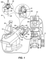
- Figure 1 illustrates a catheter-based electrophysiology mapping and ablation system 10 including an example catheter 14.
- the example catheter 14 has electrodes 40 supported by spines 110 of a support frame assembly.
- the support frame assembly can have numerous configurations, including those illustrated in Figures 2A through 10C , where: first, second, and third example basket assemblies 100, 200, 300 illustrated in Figures 2A through 4B each include at least one frame loop with a bend at a distal end of the support frame assembly; a fourth example basket assembly 400 illustrated in Figures 5A through 6B has an inner and outer support frame which can cause an inner electrode assembly to be movable between a contacting configuration and a non-contacting configuration; fifth, sixth, and seventh example basket assemblies 500, 600, 700 each have a first unitary structure having four spines and a second unitary structure having at least two spines; and an eighth example basket assembly 800 has a combination of a planar tripodic structure and a tubular tripodic structure.
- each of the example basket assemblies 100, 200, 300, 400, 500, 600, 700, 800 are combinable as disclosed here and also as understood by a person skilled in the pertinent art.
- Each of the example basket assemblies 100, 200, 300, 400, 500, 600, 700, 800 can include electrodes such as the example electrode 40 illustrated in Figure 11 .
- the profile shape of the support frame of any of the example basket assemblies 100, 200, 300, 400, 500, 600, 700, 800 can be approximately circular (thereby forming an approximately spherical shaped basket) as illustrated in Figure 12A or can be oblate (thereby forming an approximately oblate-spheroid shaped basket) as illustrated in Figure 12B . Examples are expounded upon in relation to the figures below.
- FIG. 1 is an illustration showing an example catheter-based electrophysiology mapping and ablation system 10.
- the system 10 includes multiple catheters, which are percutaneously inserted by a physician 24 through the patient's vascular system into a chamber or vascular structure of a heart 12.
- a delivery sheath catheter is inserted into the left or right atrium near a desired location in the heart 12.
- a plurality of catheters can be inserted into the delivery sheath catheter so as to arrive at the desired location.
- the plurality of catheters may include catheters dedicated for sensing Intracardiac Electrogram (IEGM) signals, catheters dedicated for ablating and/or catheters dedicated for both sensing and ablating.
- An example catheter 14 that is configured for sensing IEGM is illustrated herein.
- the physician 24 brings a distal tip 28 of the catheter 14 into contact with the heart wall for sensing a target site in the heart 12. For ablation, the physician 24 would similarly bring a distal end of an ablation catheter to a target site for ablating
- the illustrated catheter 14 is an exemplary catheter that includes one and preferably multiple electrodes 40 optionally distributed over a plurality of spines 110 of a basket assembly 100 which forms an end effector at distal tip 28 and configured to sense the IEGM signals and/or provide ablation signals.
- the basket assembly 100 illustrated in Figure 1 is compatible with every feature of the basket assemblies 100, 200, 300, 400, 500, 600, 700, 800 illustrated in Figures 2A through 10C and variations thereof as disclosed herein. Therefore catheter 14 can be modified to include any of the features related to the example basket assemblies 100, 200, 300, 400, 500, 600, 700, 800.
- Features of a given example basket assembly 100, 200, 300, 400, 500, 600, 700, 800 are inter-compatible within the given example.
- the overall basket shape can be approximately spherical ( Figure 12A ) or approximately oblate-spheroid ( Figure 12B ) for any of the example basket assemblies 100, 200, 300, 400, 500, 600, 700, 800.
- the spines 110 can be collapsed toward the longitudinal axis 86 so that the basket assembly 100 end effector (referred herein after as “basket assembly”) can be delivered through a sheath or intermediate catheter to a treatment site.
- the basket assembly 100 can be configured to expand to the illustrated basket shape when deployed, having an approximately spherical shape or an approximately oblate-spheroid shape as illustrated in profile in Figures 12A and 12B .
- the support frame assembly 100 is self-expandable upon exiting the intermediate catheter or sheath, and may include nitinol or other shape memory material suitable to facilitate self-expansion and biocompatibility.
- each spine 110 is coupled together within the shaft 84 near a proximal end of the basket assembly 100 and a distal end of the shaft 84.
- the catheter 14 can include a spine retention hub 90 that extends longitudinally through the distal end of the shaft 84.
- the spine retention hub 90 can include a cylindrical member configured to affix proximal ends of the spines 110 within the shaft 84.
- the spine retention hub 90 may include irrigation openings and/or an electrode.
- Each spine 110 can include a resilient support frame including a suitable biocompatible material to provide structural support and an insulative jacket, sleeve, or other structure electrically insulating the electrodes 40 from the support frame material.
- Each spine 110 can also include electrical conductors such as wires and/or flex circuits in electrical communication with the electrodes 40 to provide electrical communication between the electrodes 40 and other components of the system 10 (e.g. patient interface unit 30) to facilitate navigation, mapping, and/or ablation.
- the catheter 14 may additionally include a position sensor 29 embedded in or near distal tip 28 for tracking position and orientation of distal tip 28.
- position sensor 29 is a magnetic based position sensor including three magnetic coils for sensing three-dimensional (3D) position and orientation.
- a magnetic based position sensor 29 may be operated together with a location pad 25 including a plurality of magnetic coils 32 configured to generate magnetic fields in a predefined working volume. Real time position of a distal tip 28 of the catheter 14 may be tracked based on magnetic fields generated with a location pad 25 and sensed by a magnetic based position sensor 29. Details of the magnetic based position sensing technology are described in U.S. Patent Nos.
- the system 10 includes one or more electrode patches 38 positioned for skin contact on the patient 23 to establish location reference for location pad 25 as well as impedance-based tracking of electrodes 40.
- impedance-based tracking electrical current is directed toward electrodes 40 and sensed at electrode skin patches 38 so that the location of each electrode can be triangulated via the electrode patches 38. Details of the impedance-based location tracking technology are described in U.S. Patent Nos. 7,536,218 ; 7,756,576 ; 7,848,787 ; 7,869,865 ; and 8,456,182 incorporated by reference herein and attached to the Appendix of priority patent Application No. 63/476,275 .
- a recorder 11 displays electrograms 21 captured with body surface ECG electrodes 18 and intracardiac electrograms (IEGM) captured with electrodes 40 of the catheter 14.
- the recorder 11 may include pacing capability for pacing the heart rhythm and/or may be electrically connected to a standalone pacer.
- the system 10 can include an ablation energy generator 50 that is adapted to conduct ablative energy to one or more of electrodes at a distal tip of a catheter configured for ablating.
- Energy produced by the ablation energy generator 50 may include, but is not limited to, radiofrequency (RF) energy or pulsed-field ablation (PFA) energy, including monopolar or bipolar high-voltage DC pulses as may be used to effect irreversible electroporation (IRE), or combinations thereof.
- RF radiofrequency
- PFA pulsed-field ablation
- IRE irreversible electroporation
- the electrodes 40 can be configured to deliver a peak voltage of at least 900 volts (V) between electrodes 40 to achieve IRE.
- a patient interface unit (PIU) 30 is an interface configured to establish electrical communication between catheters, electrophysiological equipment, power supply and a workstation 55 for controlling operation of system 10.
- Electrophysiological equipment of the system 10 may include for example, multiple catheters, a location pad 25, body surface ECG electrodes 18, electrode patches 38, an ablation energy generator 50, and a recorder 11.
- the PIU 30 includes processing capability for implementing real-time computations of location of the catheters and for performing ECG calculations.
- the workstation 55 includes memory, processor unit with memory or storage with appropriate operating software loaded therein, and user interface capability.
- the workstation 55 can be configured to provide multiple functions, optionally including (1) modeling the endocardial anatomy in three-dimensions (3D) and rendering the model or an anatomical map 20 for display on a display device 27; (2) displaying on the display device 27 activation sequences (or other data) compiled from recorded electrograms 21 in representative visual indicia or imagery superimposed on the rendered anatomical map 20; (3) displaying real-time location and orientation of multiple catheters within the heart chamber; and (4) displaying on the display device 27 sites of interest such as places where ablation energy has been applied.
- One commercial product embodying elements of the system 10 is available as the CARTO TM 3 System, available from Biosense Webster, Inc., 31A Technology Drive, Irvine, CA 92618.
- the system 10 can further include an irrigation source (not illustrated) configured to provide irrigation fluid to the catheter 14.
- the workstation 55 can be configured to control the irrigation source to provide irrigation at the distal end 28 of the catheter 14.
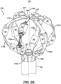
- Figure 2A is an illustration of a first example basket assembly 100 having multiple spines 110a-f and electrodes 40 coupled to the spines 110a-f.
- the spines 110a-f are distributed among a first frame loop 111, a second frame loop 112, and a third frame loop 113.
- the spines 110a-f are configured to expand away from a longitudinal axis 86 of the end effector to form a basket shape.
- the basket shape can be approximately spherical, approximately oblate-spheroid, or other suitable shape as understood by a person skilled in the art.
- the first frame loop 111 includes a first pair of spines 110a, 110d that are disposed across from each other with respect to the longitudinal axis 86.
- the second frame loop 112 is distinct from the first frame loop 111 and includes a second pair of spines 110b, 110c that are disposed on a first side of the first frame loop 111.
- the third frame loop 113 is distinct from the first frame loop 111, and the second frame loop 112 and includes a third pair of spines 110f, 110e that are disposed on a second side of the first frame loop 111.
- the first frame loop 111, second frame loop 112, and third frame loop 113 converge at a distal end 104 of the basket assembly 100.
- the first example basket assembly 100 can be configured to join with the shaft 84 via a retention hub 90 to form a catheter 14 as disclosed in relation to Figure 1 or otherwise joined to the shaft 84 as understood by a person skilled in the pertinent art.
- the electrodes 40 can be configured for navigation, mapping, and/or ablation as disclosed in relation to Figure 1 .
- Each spine 110a-f can include a support frame, an insulator electrically insulating the support frame from electrodes 40, electrical conductors in electrical communication with the electrodes 40, and other compatible features such as disclosed in relation to Figure 1 and otherwise understood by a person with pertinent skill in the art.
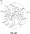
- FIG 2B is an illustration of a distal end 104 view of the first example basket assembly 100.
- the first frame loop 111 includes a distal portion 121 approximate the distal end 104 of the end effector which traverses the longitudinal axis 86.
- the first frame loop 111 bisects the basket assembly 100 so that the first side (right side in Figure 2B ) on which the second frame loop 112 is primarily disposed is opposite the second side (left side in Figure 2B ) on which the third frame loop 113 is primarily disposed.
- Each of the second frame loop 112 and the third frame loop 113 respectively include an angled portion 122, 123 at the distal end 104 of the basket assembly 100 end effector.
- the angled portion 122, 123 of each of the second and third frame loop can be coupled to the distal portion 121 of the first frame loop 111.
- Spines 110a-f are disposed symmetrically about the longitudinal axis 86 such that, collectively, spines of the first pair of spines 110a, 110d of the first frame loop 111, the second pair of spines 110b, 110c of the second frame loop 112, and the third pair of spines 1 10f, 110e of the third frame loop 113 are disposed symmetrically about the longitudinal axis 86.
- the first pair of spines 110a, 110d are disposed at an angle 131 of approximately 180° from each other with respect to an imaginary circle 70 about the longitudinal axis 86.
- the second pair of spines 110b, 110c are disposed at an angle 132 of approximately 60° from each other with respect to the imaginary circle 70.
- the third pair of spines 110e, 110f are disposed at an angle 133 of approximately 60° from each other with respect to the imaginary circle 70.
- Each angled portion 122, 123 of the second frame loop 112 and the third frame loop 113 overlaps the distal portion 121 of the first frame loop 111.
- the distal portion 121 of the first frame loop 111 is distal of the angled portions 122, 123. Configured as such, the distal portion 121 of the first frame loop 111 may shield the angled portions 122, 123 from contacting tissue, thereby providing an atraumatic distal end 104 to the basket assembly 100.
- one or both of the angled portions 122, 123 can be positioned distal of the distal portion 121 of the first frame loop 111, and the basket assembly 100 can be otherwise configured to provide an atraumatic distal end 104, for instance, by providing an atraumatic shape at one or both of the angled portions 122, 123, by covering the distal end 104 of the basket assembly 100 with an atraumatic cover or coating, etc.
- FIG 3A is an illustration of a second example basket assembly 200 having multiple spines 1 10a-f and electrodes 40 coupled to the spines 1 10a-f.
- the spines 1 10a-f and electrodes 40 are configured similarly to the spines 110a-f and electrodes 40 disclosed in relation to Figure 2A .
- the electrodes 40 can be configured for navigation, mapping, and/or ablation as disclosed in relation to Figure 1 .
- Each spine 110a-f can include a support frame, an insulator electrically insulating the support frame from electrodes 40, electrical conductors in electrical communication with the electrodes 40, and other compatible features such as disclosed in relation to Figure 1 and otherwise understood by a person with pertinent skill in the art.
- the spines 1 10a-f are distributed among a first frame loop 111, a second frame loop 212, and a third frame loop 213.
- the spines 110a-f are configured to expand away from a longitudinal axis 86 of the end effector to form a basket shape.
- the basket shape can be approximately spherical, approximately oblate-spheroid, or other suitable shape as understood by a person skilled in the art.
- the first frame loop 111 includes a first pair of spines 1 10a, 110d that are disposed across from each other with respect to the longitudinal axis 86.
- the second frame loop 212 is distinct from the first frame loop 111 and includes a second pair of spines 110b, 110c that are disposed on a first side of the first frame loop 111.
- the third frame loop 213 is distinct from the first frame loop 111, and the second frame loop 212 and includes a third pair of spines 110f, 110e that are disposed on a second side of the first frame loop 211.
- the first frame loop 211, second frame loop 212, and third frame loop 113 converge at the distal end 204 of the second example basket assembly 200.
- the second example basket assembly 200 can be configured to join with the shaft 84 via a retention hub 90 to form a catheter 14 as disclosed in relation to Figure 1 or otherwise joined to the shaft 84 as understood by a person skilled in the pertinent art.
- the second example basket assembly 200 is similar to the first example basket assembly illustrated in Figures 2A and 2B except that the distal end 204 of the second example basket assembly 200 is configured differently than the distal end 104 of the first example basket assembly 100.
- Figure 3B is an illustration of the distal end 204 of the second example basket assembly 200.
- the first frame loop 111 includes a distal portion 121 approximate the distal end 204 of the end effector which traverses the longitudinal axis 86 similar to the first frame loop 111 of the first example basket assembly 100.
- the first frame loop 111 bisects the second example basket assembly 200 so that the first side (right side in Figure 3B ) on which the second frame loop 212 is primarily disposed is opposite the second side (left side in Figure 3B ) on which the third frame loop 213 is primarily disposed.
- Each of the second frame loop 212 and the third frame loop 213 respectively include an angled portion 222, 223 at the distal end 204 of the basket assembly 200 end effector.
- Each angled portion 222, 223 abuts the distal portion 121 of the first frame loop rather than overlapping the distal portion 121 of the first frame loop as in the first example basket assembly 100.
- the angled portion 222, 223 of each of the second and third frame loop can be coupled to the distal portion 221 of the first frame loop 211.
- the second example basket assembly 200 includes a retainer 208.
- the first example basket assembly 100 can also include the retainer 208.
- the retainer 208 is illustrated as a band, but can have other alternative configurations as understood by a person skilled in the pertinent art, such as a circular hub.
- the retainer 208 can be configured to provide an atraumatic distal end 204 of the second example basket assembly 200 (or first example basket assembly 100).
- the second example basket assembly 200 can be otherwise configured to provide an atraumatic distal end 204, for instance, by providing an atraumatic shape at one or both of the angled portions 222, 223, by covering the distal end 204 of the basket assembly 200 with an atraumatic cover or coating, etc.
- Spines 110a-f are disposed symmetrically about the longitudinal axis 86 such that, collectively, spines of the first pair of spines 110a, 110d of the first frame loop 111, the second pair of spines 110b, 110c of the second frame loop 212, and the third pair of spines 1 10f, 110e of the third frame loop 213 are disposed symmetrically about the longitudinal axis 86.
- the first pair of spines 110a, 110d are disposed at an angle 131 of approximately 180° from each other with respect to an imaginary circle 70 about the longitudinal axis 86.
- the second pair of spines 110b, 110c are disposed at an angle 132 of approximately 60° from each other with respect to the imaginary circle 70.
- the third pair of spines 1 10e, 110f are disposed at an angle 133 of approximately 60° from each other with respect to the imaginary circle 70.
- Each angled portion 222, 223 of the second frame loop 212 and the third frame loop 213 abuts the distal portion 121 of the first frame loop 111.
- FIG 4A is an illustration of a third example basket assembly 300 having multiple spines 110a-f and electrodes 40 coupled to the spines 1 10a-f.
- the spines 110a-f and electrodes 40 are configured similarly to the spines 110a-f and electrodes 40 disclosed in relation to Figure 2A .
- the electrodes 40 can be configured for navigation, mapping, and/or ablation as disclosed in relation to Figure 1 .
- Each spine 110a-f can include a support frame, an insulator electrically insulating the support frame from electrodes 40, electrical conductors in electrical communication with the electrodes 40, and other compatible features such as disclosed in relation to Figure 1 and otherwise understood by a person with pertinent skill in the art.
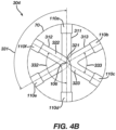
- FIG 4B is an illustration of a distal end 304 of the third example basket assembly 300.
- the spines 110a-f are distributed among a first frame loop 311, a second frame loop 312, and a third frame loop 313.
- the spines 110a-f are configured to expand away from a longitudinal axis 86 of the end effector to form a basket shape.
- the basket shape can be approximately spherical, approximately oblate-spheroid, or other suitable shape as understood by a person skilled in the art.
- the first frame loop 311 includes a first pair of spines 110a, 110e and a first angled portion 321 approximate the distal end 304 of the end effector.
- the second frame loop 312 is distinct from the first frame loop 311 and includes a second pair of spines 1 10d, 110f and a second angled portion 322 approximate the distal end 304 of the end effector such that the second angle portion 322 overlaps the first angled portion 321, an inner spine 110e of the first pair of spines 110a, 110e is positioned between spines of the second pair of spines 1 10d, 1 10f, and an inner spine 110f of the second pair of spines 110d, 110f is positioned between spines the first pair of spines 110a, 110e.
- the third frame loop 313 is distinct from the first frame loop 311 and the second frame loop 312 and includes a third pair of spines 1 10b, 110c and a third angled portion 323 approximate the distal end 304 of the end effector such that spines of the third pair of spines 110b, 110c are each disposed between outer spines 110a, 110d of the first pair of spines and the second pair of spines.
- the second example basket assembly 200 can be configured to join with the shaft 84 via a retention hub 90 to form a catheter 14 as disclosed in relation to Figure 1 or otherwise joined to the shaft 84 as understood by a person skilled in the pertinent art.
- the first angled portion 321and/or the second angled portion 322 can overlap the third angled portion 323 approximate the distal end 304 of the end effector to provide an atraumatic distal end 304.
- the angled portions 321, 322, 323 of each of the first, second, and third frame loops 311, 312, 313 can be coupled to each other.
- the third example basket assembly 300 can also include a retainer similar to the retainer 208 illustrated in Figures 3A and 3B .
- the retainer 208 is illustrated as a band, but can have other alternative configurations as understood by a person skilled in the pertinent art, such as a circular hub.
- the retainer 208 can be configured to provide an atraumatic distal end 304 of the third example basket assembly 300.
- the third example basket assembly 300 can be otherwise configured to provide an atraumatic distal end 304, for instance, by providing an atraumatic shape at one or more of the angled portions 321, 322, 323, by covering the distal end 304 of the basket assembly 200 with an atraumatic cover or coating, etc.
- Spines 110a-f are disposed symmetrically about the longitudinal axis 86 such that, collectively, spines of the first pair of spines 110a, 110e of the first frame loop 311, the second pair of spines 110d, 110f of the second frame loop 312, and the third pair of spines 110b, 110c of the third frame loop 313 are disposed symmetrically about the longitudinal axis 86.
- the first pair of spines 110a, 110e are disposed at an angle 331 of approximately 120° from each other with respect to an imaginary circle 70 about the longitudinal axis 86.
- the second pair of spines 1 10d, 110f are disposed at an angle 332 of approximately 120° from each other with respect to the imaginary circle 70.
- the third pair of spines 110b, 110c are disposed at an angle 333 of approximately 60° from each other with respect to the imaginary circle 70.
- the outer spine 110a of the first pair of spines can be disposed opposite the outer spine 110d of the second pair of spines with respect to the longitudinal axis 86.
- the inner spines 110e, 110f of the first and second pairs of spines can be positioned opposite a respective spine of the third pair of spines 1 10b, 110c.
- FIG 5A is an illustration of a fourth example basket assembly 400 having an inner electrode assembly 420 in a contacting configuration and an outer electrode assembly 420. Electrodes 40b, 40a of the inner electrode assembly 420 and outer electrode assembly 410 are coupled to spines 110a-f.
- the spines 110a-f and electrodes 40a, 40b are configured similarly to the spines 110a-f and electrodes 40 disclosed in relation to Figure 2A .
- the electrodes 40a, 40b can be configured for navigation, mapping, and/or ablation as disclosed in relation to the electrodes 40 of Figure 1 .
- Each spine 110a-f can include a support frame, an insulator electrically insulating the support frame from electrodes 40a, 40b, electrical conductors in electrical communication with the electrodes 40a, 40b, and other compatible features such as disclosed in relation to Figure 1 and otherwise understood by a person with pertinent skill in the art.
- the outer electrode assembly 410 includes a first plurality of spines 1 10a, 1 10c, 110e and a first plurality of electrodes 40a.
- the first plurality of electrodes 40a are coupled to each of the first plurality of spines 110a, 110c, 110e.
- the inner electrode assembly 420 includes a second plurality of spines 110b, 110d, 110f and a second plurality of electrodes 40b.
- the second plurality of electrodes 40b are coupled to each of the second plurality of spines 11 0b, 110d, 110f.
- the first plurality of spines 110a, 110c, 110e are configured to expand from the longitudinal axis 86 to form a basket shape
- the second plurality of spines 110b, 110d, 110f are configured to expand from the longitudinal axis 86 to form a basket shape.
- the inner and outer electrode assemblies 420, 410 can collectively form a basket shape.
- the basket shape can be approximately spherical, approximately oblate-spheroid, or other suitable shape as understood by a person skilled in the art.
- the inner electrode assembly 420 is configured to move between a non-contacting configuration and a contacting configuration.
- Figure 5A illustrates the inner electrode assembly 420 in the contacting configuration.
- the second plurality of electrodes 40b are positioned to contact tissue.
- the second plurality of spines 110b, 1 10d, 110f are out of alignment with the first plurality of spines 110a, 110c, 110e in the contacting configuration.
- Figure 5B is an illustration of a spine 110d of the inner electrode assembly 420 aligned with a spine 110c of the outer electrode assembly 410 when the inner electrode assembly 420 is in the non-contacting configuration.
- the second plurality of spines 110b, 110d, 110f are in alignment with the first plurality of spines 110a, 11 0c, 1 10e in the non-contacting configuration.
- the second plurality of electrodes 40b are inhibited, by the outer electrode assembly 410, from contacting tissue.
- the inner electrode assembly 420 can be configured to move between the non-contacting configuration ( Figure 5B ) and the contacting configuration ( Figure 5A ) by virtue of one or both of the inner and outer electrode assemblies 420, 410 rotating about the longitudinal axis 86.
- the fourth example basket assembly 400 can be configured in one of three ways to move the inner electrode assembly 420 between the non-contacting configuration and the contacting configuration: (1) the inner electrode assembly 420 can rotate about the longitudinal axis 86 while the outer electrode assembly 410 remains stationary; (2) the outer electrode assembly 410 can rotate about the longitudinal axis 86 while the inner electrode assembly 420 remains stationary; or (3) both the inner electrode assembly 420 and the outer electrode assembly 410 can rotate about the longitudinal axis 86.
- the outer electrode assembly 410 can include a first unitary tripodic structure including the first plurality of spines 110a, 11 0c, 110e such that the first plurality of spines has exactly three spines.
- the inner electrode assembly 420 can include a second unitary tripodic structure including the second plurality of spines 110b, 110d, 110f such that the second plurality of spines has exactly three spines.
- Each tripodic structure can be formed from a respective planar sheet of material that includes three linear spines converging at a respective central spine intersection 406.
- Each spine of each tripodic structure can include a respective end disposed at a proximal end of the fourth example basket assembly 400.
- the central spine intersection 406 of each tripodic structure can be positioned on the longitudinal axis 86 at a distal end of the end effector.
- Each electrode 40a, 40b of the first plurality of electrodes 40a and of the second plurality of electrodes 40b can define a lumen through the electrode so that each spine 110a-f extends through the lumen of each of the electrodes.
- the electrodes 40a, 40b can be shaped similar to as illustrated in Figure 11 , variations thereof, and alternatives thereto as understood by a person skilled in the pertinent art.
- Electrodes of the first plurality of electrodes 40a can be configured to deliver electrical pulses for irreversible electroporation.
- the pulses can have a peak voltage of at least 900 volts (V).
- Electrodes of the second plurality of electrodes 40b can be configured to map cardiac electrical signals through tissue.
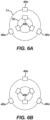
- Figure 6A is an illustration of the arrangement of electrodes 40a, 40b of the fourth example basket assembly 400 with the inner electrode assembly 420 in the non-contacting configuration.
- Figure 6B is an illustration of the arrangement of electrodes 40a, 40b of the fourth example basket assembly 400 with the inner electrode assembly 420 in the contacting configuration.
- an inner imaginary circle 72 is drawn to show the circular arrangement of the second plurality of electrodes 40b
- an outer imaginary circle 71 is drawn to show the circular arrangement of the first plurality of electrodes 40a.
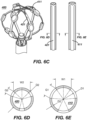
- Figure 6C shows an exemplary basket catheter 400 with two formed tubular stocks 421 and 411. When each respective tubular stock 411, 421 is expanded, they become a respective three-spined basket. Electrodes 40a, 40b, conductors, and other features can be affixed to the tube stocks 421, 411 to form the inner electrode assembly 420 and outer electrode assembly 410.
- Figure 6D shows the cross-sectional view of the tubular stock 421 of the inner electrode assembly 420 as indicated in Figure 6C .
- the tubular stock 421 has an outer diameter D2 and is cut to have spines with a width W2 and a gap G2 between spines.
- the spine width W2 is approximately 72% of the outer diameter D2.
- the gap G2 is approximately 24% of the diameter D2 or approximately 33% of the width W2 of the spine.
- FIG 6E shows the cross-sectional view of the tubular stock 411 of the outer electrode assembly 410 as indicated in Figure 6C .
- the tubular stock 411 has an outer diameter D1 and is cut to have spines with a width W1 and a gap G1 between spines.
- the spine width W1 is approximately equal to the spine width W2 of the inner tubular stock 421.
- the spine width W1 is approximately 57% of the outer diameter D1.
- the gap G1 is approximately 43% of the outer diameter D1 or approximately 75% of the width W1 of the spine.
- the outer tubular stock 411 has an inner diameter D2' that is approximately equal to the outer diameter D2 of the inner tube stock 421. When the inner tube stock 421 and outer tube stock 411 are expanded into baskets, the distal tip hole 412 of the outer tube stock 411 can be approximately the same diameter of the outer diameter D2 of the inner tube stock 421.
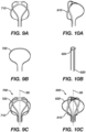
- Figure 7A is an illustration of a first unitary structure 510 of a fifth example basket assembly 500.
- the first unitary structure 510 includes four spines, and can be formed from a planar sheet of material that includes four linear spines converging at a central spine intersection.
- Figure 7B is an illustration of a second unitary structure 520 of the fifth example basket assembly 500.
- the second unitary structure 520 is distinct from the first unitary structure 510 and includes four spines.
- the second unitary structure 520 can be shaped identically as the first unitary structure 510, but need not be.
- the second unitary structure 520 can be formed from a planar sheet of material that includes the four spines converging at a central spine intersection.
- FIG 7C is an illustration of the structures 510, 520 in Figure 7A and 7B assembled to form the support frame of fifth example basket assembly 500.
- the fifth example basket assembly 500 can further include electrodes coupled to each spine of the first unitary structure 510 and the second unitary structure 520.
- the electrodes can be configured similarly to the electrodes 40 disclosed in relation to Figure 1 and in relation to Figure 11 .
- Each electrode can define a lumen through the electrode so that each spine extends through the lumen of each electrode.
- the electrodes can be configured to deliver electrical pulses for irreversible electroporation, the pulses including a peak voltage of at least 900 volts (V).
- the spines of the first unitary structure 510 and the second unitary structure 520 can be configured to expand from a longitudinal axis of the end effector to collectively form a basket shape.
- the basket shape can be approximately spherical or approximately oblate-spheroid.
- the spines of the first unitary structure 510 and the second unitary structure 520 can be positioned symmetrically about the longitudinal axis 86.
- Each spine of each unitary structure 510, 520 can include a respective connected end disposed at a proximal end of the fifth example basket assembly 500.
- the central spine intersection of each unitary structure 510, 520 can be positioned on the longitudinal axis 86 at a distal end of the basket assembly 500.
- Figure 8A is an illustration of a first unitary structure 610 of a sixth example basket assembly 600.
- the first unitary structure 610 includes four spines, and can be formed from a planar sheet of material that includes four linear spines converging at a central spine intersection.
- Figure 8B is an illustration of a second unitary structure 620 of the sixth example basket assembly 600.
- the second unitary structure 620 is distinct from the first unitary structure 610 and includes three spines.
- the second unitary structure 620 can be formed from a planar sheet of material that includes the three spines converging at a central spine intersection.
- FIG 8C is an illustration of the structures 610, 620 in Figure 8A and 8B assembled to form the support frame of sixth example basket assembly 600.
- the sixth example basket assembly 600 can further include electrodes coupled to each spine of the first unitary structure 610 and the second unitary structure 620.
- the electrodes can be configured similarly to the electrodes 40 disclosed in relation to Figure 1 and in relation to Figure 11 .
- Each electrode can define a lumen through the electrode so that each spine extends through the lumen of each electrode.
- the electrodes can be configured to deliver electrical pulses for irreversible electroporation, the pulses including a peak voltage of at least 900 volts (V).
- the spines of the first unitary structure 610 and the second unitary structure 620 can be configured to expand from a longitudinal axis of the end effector to collectively form a basket shape.
- the basket shape can be approximately spherical or approximately oblate-spheroid.
- the spines of the first unitary structure 610 and the second unitary structure 620 can be positioned symmetrically about the longitudinal axis 86.
- Each spine of each unitary structure 610, 620 can include a respective connected end disposed at a proximal end of the sixth example basket assembly 600.
- the central spine intersection of each unitary structure 610, 620 can be positioned on the longitudinal axis 86 at a distal end of the basket assembly 600.
- Figure 9A is an illustration of a first unitary structure 710 of a seventh example basket assembly 700.
- the first unitary structure 710 includes four spines, and can be formed from a planar sheet of material that includes four linear spines converging at a central spine intersection.
- Figure 9B is an illustration of a second unitary structure 720 of the seventh example basket assembly 700.
- the second unitary structure 720 is distinct from the first unitary structure 710 and includes two spines.
- the second unitary structure 720 can be shaped from a single elongated spine shaped to form a loop.
- the second unitary structure 720 can be formed from a planar sheet of material. The central point of the loop is considered a central spine intersection.
- Figure 9C is an illustration of the structures 710, 720 in Figure 9A and 9B assembled to form the support frame of seventh example basket assembly 700.
- the second unitary structure 720 can include a loop extending across the central spine intersection of the first unitary structure 710 such that two spines of the first unitary structure 710 are disposed on a first side of the loop 720 and two spines of the first unitary structure 710 are disposed on a second side of the loop 720.
- the seventh example basket assembly 700 can further include electrodes coupled to each spine of the first unitary structure 710 and the second unitary structure 720.
- the electrodes can be configured similarly to the electrodes 40 disclosed in relation to Figure 1 and in relation to Figure 11 .
- Each electrode can define a lumen through the electrode so that each spine extends through the lumen of each electrode.
- the electrodes can be configured to deliver electrical pulses for irreversible electroporation, the pulses including a peak voltage of at least 900 volts (V).
- the spines of the first unitary structure 710 and the second unitary structure 720 can be configured to expand from a longitudinal axis of the end effector to collectively form a basket shape.
- the basket shape can be approximately spherical or approximately oblate-spheroid.
- the spines of the first unitary structure 710 and the second unitary structure 720 can be positioned symmetrically about the longitudinal axis 86.
- Each spine of each unitary structure 710, 720 can include a respective connected end disposed at a proximal end of the seventh example basket assembly 700.
- the central spine intersection of each unitary structure 710, 720 can be positioned on the longitudinal axis 86 at a distal end of the basket assembly 700.
- Figure 10A is an illustration of a first unitary structure 810 of an eighth example basket assembly 800.
- the first unitary structure 810 includes three spines, and can be formed from a planar sheet of material that includes three linear spines converging at a central spine intersection.
- Figure 10B is an illustration of a second unitary structure 820 of the eighth example basket assembly 800.
- the second unitary structure 820 is distinct from the first unitary structure 810 and includes three spines.
- the second unitary structure 820 can be formed from a tube of material that includes the at least two spines joined at one end by a ring.
- Figure 10C is an illustration of the structures 810, 820 in Figure 10A and 10B assembled to form the support frame of eighth example basket assembly 800.
- the eighth example basket assembly 800 can further include electrodes coupled to each spine of the first unitary structure 810 and the second unitary structure 820.
- the electrodes can be configured similarly to the electrodes 40 disclosed in relation to Figure 1 and in relation to Figure 11 .
- Each electrode can define a lumen through the electrode so that each spine extends through the lumen of each electrode.
- the electrodes can be configured to deliver electrical pulses for irreversible electroporation, the pulses including a peak voltage of at least 900 volts (V).
- the spines of the first unitary structure 810 and the second unitary structure 820 can be configured to expand from a longitudinal axis of the end effector to collectively form a basket shape.
- the basket shape can be approximately spherical or approximately oblate-spheroid.
- the spines of the first unitary structure 810 and the second unitary structure 820 can be positioned symmetrically about the longitudinal axis 86.
- Each spine of each unitary structure 810, 820 can include a respective connected end disposed at a proximal end of the eighth example basket assembly 800.
- the central spine intersection of each unitary structure 810, 820 can be positioned on the longitudinal axis 86 at a distal end of the basket assembly 800.
- FIG 11 is an illustration of an electrode 40.
- the electrode defines a lumen 48 through the electrode 40 so that a spine can extends through the lumen 48.
- the electrode has an outer surface 44 that is exposed to ambient environment and an inner surface 46 within the lumen 48.
- the electrode 40 can include electrically conductive material (e.g., gold, platinum and palladium (and their respective alloys)).
- the electrode 40 can have a variety of cross-sectional shapes, curvatures, lengths, lumen number and lumen shapes.
- the electrode 40 illustrated in Figure 11 and elsewhere herein are offered to illustrate various configurations of electrodes 40 that can be used with the catheter 14 but should not be construed as limiting.
- the electrodes 40 includes a wire relief 42 forming a recess or depression in the electrode 40 adjacent the lumen 48 for one or more wires to pass through the lumen 48 along with a respective spine 110.
- Relief 42 can be sized to provide room for a wire of electrode 40 to pass through electrode 40 such that electrode 40 can be in electrical communication with the control console PIU 30 ( Figure 1 ).
- Figure 12A is an illustration of a frame loop with an approximately circular cross-section which illustrates a profile of a basket assembly having a basket shape that is approximately spherical.
- Any of the example basket assemblies 100, 200, 300, 400, 500, 600, 700, 800 can be shaped to have a basket shape that is approximately spherical.
- Figure 12B is an illustration of a frame loop with an oblate cross-section which illustrates a profile of a basket assembly having a basket shape that is approximately oblate-spheroid.
- Any of the example basket assemblies 100, 200, 300, 400, 500, 600, 700, 800 can be shaped to have a basket shape that is approximately oblate-spheroid.
Landscapes
- Health & Medical Sciences (AREA)
- Life Sciences & Earth Sciences (AREA)
- Engineering & Computer Science (AREA)
- Surgery (AREA)
- General Health & Medical Sciences (AREA)
- Biomedical Technology (AREA)
- Public Health (AREA)
- Veterinary Medicine (AREA)
- Medical Informatics (AREA)
- Molecular Biology (AREA)
- Physics & Mathematics (AREA)
- Animal Behavior & Ethology (AREA)
- Heart & Thoracic Surgery (AREA)
- Plasma & Fusion (AREA)
- Nuclear Medicine, Radiotherapy & Molecular Imaging (AREA)
- Otolaryngology (AREA)
- Cardiology (AREA)
- Biophysics (AREA)
- Pathology (AREA)
- Physiology (AREA)
- Surgical Instruments (AREA)
- Human Computer Interaction (AREA)
Applications Claiming Priority (2)
| Application Number | Priority Date | Filing Date | Title |
|---|---|---|---|
| US202263476275P | 2022-12-20 | 2022-12-20 | |
| US18/506,529 US20240197392A1 (en) | 2022-12-20 | 2023-11-10 | Multi-electrode basket end effector of a catheter |
Publications (1)
| Publication Number | Publication Date |
|---|---|
| EP4389036A1 true EP4389036A1 (de) | 2024-06-26 |
Family
ID=89224341
Family Applications (1)
| Application Number | Title | Priority Date | Filing Date |
|---|---|---|---|
| EP23217963.0A Pending EP4389036A1 (de) | 2022-12-20 | 2023-12-19 | Multielektrodenkorbendeffektor eines katheters |
Country Status (4)
| Country | Link |
|---|---|
| US (1) | US20240197392A1 (de) |
| EP (1) | EP4389036A1 (de) |
| JP (1) | JP2024088621A (de) |
| IL (1) | IL309306A (de) |
Citations (28)
| Publication number | Priority date | Publication date | Assignee | Title |
|---|---|---|---|---|
| US5391199A (en) | 1993-07-20 | 1995-02-21 | Biosense, Inc. | Apparatus and method for treating cardiac arrhythmias |
| US5558091A (en) | 1993-10-06 | 1996-09-24 | Biosense, Inc. | Magnetic determination of position and orientation |
| US6172499B1 (en) | 1999-10-29 | 2001-01-09 | Ascension Technology Corporation | Eddy current error-reduced AC magnetic position measurement system |
| US6239724B1 (en) | 1997-12-30 | 2001-05-29 | Remon Medical Technologies, Ltd. | System and method for telemetrically providing intrabody spatial position |
| US6332089B1 (en) | 1996-02-15 | 2001-12-18 | Biosense, Inc. | Medical procedures and apparatus using intrabody probes |
| US6484118B1 (en) | 2000-07-20 | 2002-11-19 | Biosense, Inc. | Electromagnetic position single axis system |
| US6618612B1 (en) | 1996-02-15 | 2003-09-09 | Biosense, Inc. | Independently positionable transducers for location system |
| US6690963B2 (en) | 1995-01-24 | 2004-02-10 | Biosense, Inc. | System for determining the location and orientation of an invasive medical instrument |
| US6892091B1 (en) | 2000-02-18 | 2005-05-10 | Biosense, Inc. | Catheter, method and apparatus for generating an electrical map of a chamber of the heart |
| US7536218B2 (en) | 2005-07-15 | 2009-05-19 | Biosense Webster, Inc. | Hybrid magnetic-based and impedance-based position sensing |
| US7756576B2 (en) | 2005-08-26 | 2010-07-13 | Biosense Webster, Inc. | Position sensing and detection of skin impedance |
| US7848787B2 (en) | 2005-07-08 | 2010-12-07 | Biosense Webster, Inc. | Relative impedance measurement |
| US7869865B2 (en) | 2005-01-07 | 2011-01-11 | Biosense Webster, Inc. | Current-based position sensing |
| US8456182B2 (en) | 2008-09-30 | 2013-06-04 | Biosense Webster, Inc. | Current localization tracker |
| US20150208937A1 (en) * | 2014-01-28 | 2015-07-30 | John Bullinga | Catheter system for mapping of the left atrium, right atrium and coronary sinus |
| US20170071543A1 (en) * | 2015-09-14 | 2017-03-16 | Biosense Webster (Israel) Ltd. | Convertible basket catheter |
| US20170100075A1 (en) * | 2013-03-08 | 2017-04-13 | St. Jude Medical, Atrial Fibrillation Division, Inc. | Basket for a multi-electrode array catheter |
| EP3430996A1 (de) * | 2017-07-17 | 2019-01-23 | Biosense Webster (Israel) Ltd. | Katheter mit verteilten fibonacci-elektroden |
| US20190282116A1 (en) * | 2018-03-13 | 2019-09-19 | St. Jude Medical, Cardiology Division, Inc. | Variable density mapping catheter |
| EP3733103A1 (de) * | 2019-04-30 | 2020-11-04 | Biosense Webster (Israel) Ltd. | Abbildungsgitter mit einer elektrodenanordnung hoher dichte |
| US20210161592A1 (en) | 2019-12-03 | 2021-06-03 | Biosense Webster (Israel) Ltd. | Pulse Generator for Irreversible Electroporation |
| US20210169567A1 (en) | 2019-12-09 | 2021-06-10 | Biosense Webster (Israel) Ltd. | Irreversible-electroporation (ire) balloon catheter with membrane-insulated high-voltage balloon wires |
| US20210169550A1 (en) | 2019-12-05 | 2021-06-10 | Biosense Webster (Israel) Ltd. | Generating and interleaving of irreversible-electroporation and radiofrequnecy ablation (ire/rfa) waveforms |
| US20210169568A1 (en) | 2019-12-09 | 2021-06-10 | Biosense Webster (Israel) Ltd. | Oriented irreversible-electroporation (ire) pulses to compensate for cell size and orientation |
| US20210177503A1 (en) | 2019-12-11 | 2021-06-17 | Biosense Webster (Israel) Ltd. | Regulating delivery of irreversible electroporation pulses according to transferred energy |
| US20210186604A1 (en) | 2019-12-24 | 2021-06-24 | Biosense Webster (Israel) Ltd. | Irreversible electroporation (ire) based on field, contact force and time |
| US20210196372A1 (en) | 2019-12-31 | 2021-07-01 | Biosense Webster (Israel) Ltd. | Using irrigation on irreversible-electroporation (ire) electrodes to prevent arcing |
| WO2022214953A1 (en) * | 2021-04-06 | 2022-10-13 | Acclarent, Inc. | Ent instrument with rf electrodes on wire frame |
-
2023
- 2023-11-10 US US18/506,529 patent/US20240197392A1/en active Pending
- 2023-12-12 IL IL309306A patent/IL309306A/en unknown
- 2023-12-19 JP JP2023213661A patent/JP2024088621A/ja active Pending
- 2023-12-19 EP EP23217963.0A patent/EP4389036A1/de active Pending
Patent Citations (30)
| Publication number | Priority date | Publication date | Assignee | Title |
|---|---|---|---|---|
| US5391199A (en) | 1993-07-20 | 1995-02-21 | Biosense, Inc. | Apparatus and method for treating cardiac arrhythmias |
| US5443489A (en) | 1993-07-20 | 1995-08-22 | Biosense, Inc. | Apparatus and method for ablation |
| US5558091A (en) | 1993-10-06 | 1996-09-24 | Biosense, Inc. | Magnetic determination of position and orientation |
| US6690963B2 (en) | 1995-01-24 | 2004-02-10 | Biosense, Inc. | System for determining the location and orientation of an invasive medical instrument |
| US6332089B1 (en) | 1996-02-15 | 2001-12-18 | Biosense, Inc. | Medical procedures and apparatus using intrabody probes |
| US6618612B1 (en) | 1996-02-15 | 2003-09-09 | Biosense, Inc. | Independently positionable transducers for location system |
| US6788967B2 (en) | 1997-05-14 | 2004-09-07 | Biosense, Inc. | Medical diagnosis, treatment and imaging systems |
| US6239724B1 (en) | 1997-12-30 | 2001-05-29 | Remon Medical Technologies, Ltd. | System and method for telemetrically providing intrabody spatial position |
| US6172499B1 (en) | 1999-10-29 | 2001-01-09 | Ascension Technology Corporation | Eddy current error-reduced AC magnetic position measurement system |
| US6892091B1 (en) | 2000-02-18 | 2005-05-10 | Biosense, Inc. | Catheter, method and apparatus for generating an electrical map of a chamber of the heart |
| US6484118B1 (en) | 2000-07-20 | 2002-11-19 | Biosense, Inc. | Electromagnetic position single axis system |
| US7869865B2 (en) | 2005-01-07 | 2011-01-11 | Biosense Webster, Inc. | Current-based position sensing |
| US7848787B2 (en) | 2005-07-08 | 2010-12-07 | Biosense Webster, Inc. | Relative impedance measurement |
| US7536218B2 (en) | 2005-07-15 | 2009-05-19 | Biosense Webster, Inc. | Hybrid magnetic-based and impedance-based position sensing |
| US7756576B2 (en) | 2005-08-26 | 2010-07-13 | Biosense Webster, Inc. | Position sensing and detection of skin impedance |
| US8456182B2 (en) | 2008-09-30 | 2013-06-04 | Biosense Webster, Inc. | Current localization tracker |
| US20170100075A1 (en) * | 2013-03-08 | 2017-04-13 | St. Jude Medical, Atrial Fibrillation Division, Inc. | Basket for a multi-electrode array catheter |
| US20150208937A1 (en) * | 2014-01-28 | 2015-07-30 | John Bullinga | Catheter system for mapping of the left atrium, right atrium and coronary sinus |
| US20170071543A1 (en) * | 2015-09-14 | 2017-03-16 | Biosense Webster (Israel) Ltd. | Convertible basket catheter |
| EP3430996A1 (de) * | 2017-07-17 | 2019-01-23 | Biosense Webster (Israel) Ltd. | Katheter mit verteilten fibonacci-elektroden |
| US20190282116A1 (en) * | 2018-03-13 | 2019-09-19 | St. Jude Medical, Cardiology Division, Inc. | Variable density mapping catheter |
| EP3733103A1 (de) * | 2019-04-30 | 2020-11-04 | Biosense Webster (Israel) Ltd. | Abbildungsgitter mit einer elektrodenanordnung hoher dichte |
| US20210161592A1 (en) | 2019-12-03 | 2021-06-03 | Biosense Webster (Israel) Ltd. | Pulse Generator for Irreversible Electroporation |
| US20210169550A1 (en) | 2019-12-05 | 2021-06-10 | Biosense Webster (Israel) Ltd. | Generating and interleaving of irreversible-electroporation and radiofrequnecy ablation (ire/rfa) waveforms |
| US20210169567A1 (en) | 2019-12-09 | 2021-06-10 | Biosense Webster (Israel) Ltd. | Irreversible-electroporation (ire) balloon catheter with membrane-insulated high-voltage balloon wires |
| US20210169568A1 (en) | 2019-12-09 | 2021-06-10 | Biosense Webster (Israel) Ltd. | Oriented irreversible-electroporation (ire) pulses to compensate for cell size and orientation |
| US20210177503A1 (en) | 2019-12-11 | 2021-06-17 | Biosense Webster (Israel) Ltd. | Regulating delivery of irreversible electroporation pulses according to transferred energy |
| US20210186604A1 (en) | 2019-12-24 | 2021-06-24 | Biosense Webster (Israel) Ltd. | Irreversible electroporation (ire) based on field, contact force and time |
| US20210196372A1 (en) | 2019-12-31 | 2021-07-01 | Biosense Webster (Israel) Ltd. | Using irrigation on irreversible-electroporation (ire) electrodes to prevent arcing |
| WO2022214953A1 (en) * | 2021-04-06 | 2022-10-13 | Acclarent, Inc. | Ent instrument with rf electrodes on wire frame |
Also Published As
| Publication number | Publication date |
|---|---|
| US20240197392A1 (en) | 2024-06-20 |
| IL309306A (en) | 2024-07-01 |
| JP2024088621A (ja) | 2024-07-02 |
Similar Documents
| Publication | Publication Date | Title |
|---|---|---|
| US20230225784A1 (en) | Systems and methods for tripodic spines forming a spherical basket for improved tissue contact and current delivery | |
| EP4389036A1 (de) | Multielektrodenkorbendeffektor eines katheters | |
| EP4393426A2 (de) | Multielektrodenkatheter mit verschachteltem substrat | |
| EP4393425A1 (de) | Verformter wirbelsäulenelektrodenkorb und verfahren dafür | |
| EP4393432A2 (de) | Ablationskatheter mit einem ausweitbaren gewebe mit elektrisch leitenden strängen | |
| EP4393434A1 (de) | Korbkatheter mit einer kombination aus wirbelsäulenstrukturen | |
| EP4382060A1 (de) | Elektroden für korbkatheter | |
| EP4268748A2 (de) | Spülnabe für einen ablationskatheter | |
| CN118216996A (zh) | 导管的多电极篮式端部执行器 | |
| EP4393424A1 (de) | Korbendeffektor mit distalem positionssensor | |
| EP4393378A2 (de) | Systeme und verfahren für mapping- und ablationskatheter mit zylindrischem käfig mit flexiblen schaltungen | |
| US20240156524A1 (en) | Electrode catheter with corrugated support structure | |
| US20240215854A1 (en) | Cylindrical cage systems and methods for distributed tissue contact for mapping and ablation | |
| EP4393430A1 (de) | Systeme und verfahren für mapping- und ablationskatheter mit zylindrischem käfig mit flexiblen schaltungen | |
| US20240216055A1 (en) | Fractal cylindrical cage systems and methods for distributed tissue contact for mapping and ablation | |
| CN118252589A (zh) | 变形的脊电极篮及其方法 | |
| CN118266935A (zh) | 结合脊状物结构的篮状导管 | |
| CN118267088A (zh) | 带有具有导电股线的可扩张编织网的消融导管 | |
| IL309727A (en) | Irrigation center for ablation catheter | |
| CN118266938A (zh) | 具有交错衬底的多电极导管 | |
| CN118141505A (zh) | 用于篮式导管的电极 | |
| CN117598771A (zh) | 用于组合消融模态的导管、系统和方法 |
Legal Events
| Date | Code | Title | Description |
|---|---|---|---|
| PUAI | Public reference made under article 153(3) epc to a published international application that has entered the european phase |
Free format text: ORIGINAL CODE: 0009012 |
|
| STAA | Information on the status of an ep patent application or granted ep patent |
Free format text: STATUS: THE APPLICATION HAS BEEN PUBLISHED |
|
| AK | Designated contracting states |
Kind code of ref document: A1 Designated state(s): AL AT BE BG CH CY CZ DE DK EE ES FI FR GB GR HR HU IE IS IT LI LT LU LV MC ME MK MT NL NO PL PT RO RS SE SI SK SM TR |