EP4386933A1 - Master-slave-verbindungskapazitätserweiterungsverfahren und -vorrichtung für mobile batterie - Google Patents
Master-slave-verbindungskapazitätserweiterungsverfahren und -vorrichtung für mobile batterie Download PDFInfo
- Publication number
- EP4386933A1 EP4386933A1 EP23771752.5A EP23771752A EP4386933A1 EP 4386933 A1 EP4386933 A1 EP 4386933A1 EP 23771752 A EP23771752 A EP 23771752A EP 4386933 A1 EP4386933 A1 EP 4386933A1
- Authority
- EP
- European Patent Office
- Prior art keywords
- battery
- voltage
- master
- slave
- discharge
- Prior art date
- Legal status (The legal status is an assumption and is not a legal conclusion. Google has not performed a legal analysis and makes no representation as to the accuracy of the status listed.)
- Pending
Links
Images

Classifications
-
- H—ELECTRICITY
- H01—ELECTRIC ELEMENTS
- H01M—PROCESSES OR MEANS, e.g. BATTERIES, FOR THE DIRECT CONVERSION OF CHEMICAL ENERGY INTO ELECTRICAL ENERGY
- H01M10/00—Secondary cells; Manufacture thereof
- H01M10/42—Methods or arrangements for servicing or maintenance of secondary cells or secondary half-cells
-
- H—ELECTRICITY
- H02—GENERATION; CONVERSION OR DISTRIBUTION OF ELECTRIC POWER
- H02J—ELECTRIC POWER NETWORKS; CIRCUIT ARRANGEMENTS OR SYSTEMS FOR SUPPLYING OR DISTRIBUTING ELECTRIC POWER; SYSTEMS FOR STORING ELECTRIC ENERGY
- H02J7/00—Circuit arrangements for charging or discharging batteries or for supplying loads from batteries
- H02J7/90—Regulation of charging or discharging current or voltage
- H02J7/933—Regulation of charging or discharging current or voltage the cycle being controlled or terminated in response to electric parameters
-
- H—ELECTRICITY
- H01—ELECTRIC ELEMENTS
- H01M—PROCESSES OR MEANS, e.g. BATTERIES, FOR THE DIRECT CONVERSION OF CHEMICAL ENERGY INTO ELECTRICAL ENERGY
- H01M10/00—Secondary cells; Manufacture thereof
- H01M10/42—Methods or arrangements for servicing or maintenance of secondary cells or secondary half-cells
- H01M10/44—Methods for charging or discharging
- H01M10/441—Methods for charging or discharging for several batteries or cells simultaneously or sequentially
-
- H—ELECTRICITY
- H02—GENERATION; CONVERSION OR DISTRIBUTION OF ELECTRIC POWER
- H02J—ELECTRIC POWER NETWORKS; CIRCUIT ARRANGEMENTS OR SYSTEMS FOR SUPPLYING OR DISTRIBUTING ELECTRIC POWER; SYSTEMS FOR STORING ELECTRIC ENERGY
- H02J7/00—Circuit arrangements for charging or discharging batteries or for supplying loads from batteries
- H02J7/34—Parallel operation in networks using both storage and other DC sources, e.g. providing buffering
- H02J7/342—The other DC source being a battery actively interacting with the first one, i.e. battery to battery charging
-
- H—ELECTRICITY
- H02—GENERATION; CONVERSION OR DISTRIBUTION OF ELECTRIC POWER
- H02J—ELECTRIC POWER NETWORKS; CIRCUIT ARRANGEMENTS OR SYSTEMS FOR SUPPLYING OR DISTRIBUTING ELECTRIC POWER; SYSTEMS FOR STORING ELECTRIC ENERGY
- H02J7/00—Circuit arrangements for charging or discharging batteries or for supplying loads from batteries
- H02J7/40—Circuit arrangements for charging or discharging batteries or for supplying loads from batteries characterised by the exchange of charge or discharge related data
-
- H—ELECTRICITY
- H02—GENERATION; CONVERSION OR DISTRIBUTION OF ELECTRIC POWER
- H02J—ELECTRIC POWER NETWORKS; CIRCUIT ARRANGEMENTS OR SYSTEMS FOR SUPPLYING OR DISTRIBUTING ELECTRIC POWER; SYSTEMS FOR STORING ELECTRIC ENERGY
- H02J7/00—Circuit arrangements for charging or discharging batteries or for supplying loads from batteries
- H02J7/50—Circuit arrangements for charging or discharging batteries or for supplying loads from batteries acting upon multiple batteries simultaneously or sequentially
-
- H—ELECTRICITY
- H02—GENERATION; CONVERSION OR DISTRIBUTION OF ELECTRIC POWER
- H02J—ELECTRIC POWER NETWORKS; CIRCUIT ARRANGEMENTS OR SYSTEMS FOR SUPPLYING OR DISTRIBUTING ELECTRIC POWER; SYSTEMS FOR STORING ELECTRIC ENERGY
- H02J7/00—Circuit arrangements for charging or discharging batteries or for supplying loads from batteries
- H02J7/60—Circuit arrangements for charging or discharging batteries or for supplying loads from batteries including safety or protection arrangements
- H02J7/63—Circuit arrangements for charging or discharging batteries or for supplying loads from batteries including safety or protection arrangements against overdischarge
-
- H—ELECTRICITY
- H02—GENERATION; CONVERSION OR DISTRIBUTION OF ELECTRIC POWER
- H02J—ELECTRIC POWER NETWORKS; CIRCUIT ARRANGEMENTS OR SYSTEMS FOR SUPPLYING OR DISTRIBUTING ELECTRIC POWER; SYSTEMS FOR STORING ELECTRIC ENERGY
- H02J7/00—Circuit arrangements for charging or discharging batteries or for supplying loads from batteries
- H02J7/60—Circuit arrangements for charging or discharging batteries or for supplying loads from batteries including safety or protection arrangements
- H02J7/64—Circuit arrangements for charging or discharging batteries or for supplying loads from batteries including safety or protection arrangements against overvoltage
-
- H—ELECTRICITY
- H02—GENERATION; CONVERSION OR DISTRIBUTION OF ELECTRIC POWER
- H02J—ELECTRIC POWER NETWORKS; CIRCUIT ARRANGEMENTS OR SYSTEMS FOR SUPPLYING OR DISTRIBUTING ELECTRIC POWER; SYSTEMS FOR STORING ELECTRIC ENERGY
- H02J7/00—Circuit arrangements for charging or discharging batteries or for supplying loads from batteries
- H02J7/855—Circuit arrangements for charging or discharging batteries or for supplying loads from batteries with circuits adapted for supplying loads from the battery
-
- H—ELECTRICITY
- H02—GENERATION; CONVERSION OR DISTRIBUTION OF ELECTRIC POWER
- H02J—ELECTRIC POWER NETWORKS; CIRCUIT ARRANGEMENTS OR SYSTEMS FOR SUPPLYING OR DISTRIBUTING ELECTRIC POWER; SYSTEMS FOR STORING ELECTRIC ENERGY
- H02J7/00—Circuit arrangements for charging or discharging batteries or for supplying loads from batteries
- H02J7/90—Regulation of charging or discharging current or voltage
- H02J7/94—Regulation of charging or discharging current or voltage in response to battery current
-
- H—ELECTRICITY
- H02—GENERATION; CONVERSION OR DISTRIBUTION OF ELECTRIC POWER
- H02J—ELECTRIC POWER NETWORKS; CIRCUIT ARRANGEMENTS OR SYSTEMS FOR SUPPLYING OR DISTRIBUTING ELECTRIC POWER; SYSTEMS FOR STORING ELECTRIC ENERGY
- H02J7/00—Circuit arrangements for charging or discharging batteries or for supplying loads from batteries
- H02J7/90—Regulation of charging or discharging current or voltage
- H02J7/96—Regulation of charging or discharging current or voltage in response to battery voltage
-
- H—ELECTRICITY
- H02—GENERATION; CONVERSION OR DISTRIBUTION OF ELECTRIC POWER
- H02J—ELECTRIC POWER NETWORKS; CIRCUIT ARRANGEMENTS OR SYSTEMS FOR SUPPLYING OR DISTRIBUTING ELECTRIC POWER; SYSTEMS FOR STORING ELECTRIC ENERGY
- H02J9/00—Circuit arrangements for emergency or stand-by power supply, e.g. for emergency lighting
- H02J9/04—Circuit arrangements for emergency or stand-by power supply, e.g. for emergency lighting in which the distribution system is disconnected from the normal source and connected to a standby source
- H02J9/06—Circuit arrangements for emergency or stand-by power supply, e.g. for emergency lighting in which the distribution system is disconnected from the normal source and connected to a standby source with automatic change-over, e.g. UPS systems
- H02J9/061—Circuit arrangements for emergency or stand-by power supply, e.g. for emergency lighting in which the distribution system is disconnected from the normal source and connected to a standby source with automatic change-over, e.g. UPS systems for DC powered loads
-
- H—ELECTRICITY
- H01—ELECTRIC ELEMENTS
- H01M—PROCESSES OR MEANS, e.g. BATTERIES, FOR THE DIRECT CONVERSION OF CHEMICAL ENERGY INTO ELECTRICAL ENERGY
- H01M10/00—Secondary cells; Manufacture thereof
- H01M10/42—Methods or arrangements for servicing or maintenance of secondary cells or secondary half-cells
- H01M10/425—Structural combination with electronic components, e.g. electronic circuits integrated to the outside of the casing
- H01M2010/4271—Battery management systems including electronic circuits, e.g. control of current or voltage to keep battery in healthy state, cell balancing
-
- H—ELECTRICITY
- H02—GENERATION; CONVERSION OR DISTRIBUTION OF ELECTRIC POWER
- H02J—ELECTRIC POWER NETWORKS; CIRCUIT ARRANGEMENTS OR SYSTEMS FOR SUPPLYING OR DISTRIBUTING ELECTRIC POWER; SYSTEMS FOR STORING ELECTRIC ENERGY
- H02J9/00—Circuit arrangements for emergency or stand-by power supply, e.g. for emergency lighting
- H02J9/04—Circuit arrangements for emergency or stand-by power supply, e.g. for emergency lighting in which the distribution system is disconnected from the normal source and connected to a standby source
- H02J9/06—Circuit arrangements for emergency or stand-by power supply, e.g. for emergency lighting in which the distribution system is disconnected from the normal source and connected to a standby source with automatic change-over, e.g. UPS systems
-
- Y—GENERAL TAGGING OF NEW TECHNOLOGICAL DEVELOPMENTS; GENERAL TAGGING OF CROSS-SECTIONAL TECHNOLOGIES SPANNING OVER SEVERAL SECTIONS OF THE IPC; TECHNICAL SUBJECTS COVERED BY FORMER USPC CROSS-REFERENCE ART COLLECTIONS [XRACs] AND DIGESTS
- Y02—TECHNOLOGIES OR APPLICATIONS FOR MITIGATION OR ADAPTATION AGAINST CLIMATE CHANGE
- Y02E—REDUCTION OF GREENHOUSE GAS [GHG] EMISSIONS, RELATED TO ENERGY GENERATION, TRANSMISSION OR DISTRIBUTION
- Y02E60/00—Enabling technologies; Technologies with a potential or indirect contribution to GHG emissions mitigation
- Y02E60/10—Energy storage using batteries
Definitions
- the present disclosure relates to the technical field of dynamic capacity expansion, and in particular to a method and a device for master-slave cooperative capacity expansion of the mobile battery.
- the capacity of the single portable mobile battery is often insufficient to meet the power needs.
- one technical solution to solve the problem is to provide two portable mobile batteries in the same model, with one portable mobile battery serving as the battery master and the other portable mobile battery serving as the battery slave.
- the cooperative capacity expansion method in which the battery master and battery slave are connected in parallel, it is possible to increase the battery capacity.
- the method of increasing battery capacity makes parallel power supply less safe and less efficient due to the fact that the battery master and battery slave, which are connected in parallel, are susceptible to short-circuit or over-voltage or over-discharge in the process of parallel power supply.
- an object of the present disclosure is to provide a method and a device for master-slave cooperative capacity expansion of the mobile battery to improve the safety of parallel power supply as well as the efficiency of power supply.
- embodiments of the present disclosure provide a method for master-slave cooperative capacity expansion of mobile battery, comprising:
- embodiments of the present disclosure provide the first possible implementation of the first aspect, wherein the step of determining the external power device as the battery slave comprises: sending a predefined command to the external power device, and determining whether the external power device is the battery slave based on the response from the external power device to the command.
- embodiments of the present disclosure provide a second possible implementation of the first aspect, wherein the step of determining whether the external power device is the battery slave based on the response from the external power device to the command comprises:
- embodiments of the present disclosure provide a third possible implementation of the first aspect, wherein the method further comprises: reading, if the master voltage is greater than or equal to the voltage, the master voltage and the battery slave voltage at a pre-set reading cycle of voltage until the master voltage becomes less than the voltage.
- embodiments of the present disclosure provide a fourth possible implementation of the first aspect, wherein the step of controlling the discharge circuit to discharge the battery slave based on the discharge current of the discharge circuit as well as the pre-set first current threshold and second current threshold comprises:
- embodiments of the present disclosure provide a fifth possible implementation of the first aspect, wherein the method further comprises: discharging, if the voltage difference is greater than or equal to the voltage difference threshold, the battery slave, and reading the voltage of the battery slave in accordance with a pre-set reading cycle of voltage difference until the voltage difference is less than the voltage difference threshold.
- embodiments of the present disclosure provide a sixth possible implementation of the first aspect, wherein the method further comprises: switching, if it is determined that the voltage is not in the pre-set voltage threshold range, the power state of the battery master to the power abnormal state; and when the voltage exceeds the upper-limit voltage threshold of the voltage threshold range, triggering the pre-set overvoltage protection circuit.
- embodiments of the present disclosure further provide a device for master-slave cooperative capacity expansion of mobile battery, comprising:
- embodiments of the present disclosure provide a computer device, comprising a memory, a processor, and a computer program stored on the memory and executable on the processor.
- the processor when executing the computer program, implements the steps of the above-mentioned method.
- embodiments of the present disclosure provide a computer-readable storage medium, wherein the computer-readable storage medium stores a computer program.
- the computer program When the computer program is executed by the processor, it performs the steps of the above-mentioned method.
- the embodiments of the present disclosure provide a method and a device for master-slave cooperative capacity expansion of a mobile battery.
- the method includes determining whether the voltage of the connected external power device is in a pre-set voltage threshold range; determining, if the voltage is higher than the master voltage of the battery master, the external power device as the battery slave; turning on, if the voltage difference between the voltage and the master voltage is smaller than a pre-set voltage difference threshold, the discharge circuit between the battery slave and the battery master; and controlling the circuit to discharge the battery slave based on the discharge current of the discharge circuit as well as the pre-set first and second current thresholds.
- the switching in and out of the battery slave can be realized, which can avoid short-circuit, overvoltage, or over-discharge during parallel power supply, thereby effectively improving the safety and power-supply efficiency of parallel power supply.
- a battery management system (BMS) is built into the battery slave. Since the battery management system has a series of protection functions such as over-temperature, over-discharge, over-current, and short-circuit, it enables the battery slave to provide capacity expansion demand for the battery master and communicate with the battery master through the built-in BMS of the battery slave.
- the battery master can obtain the type of connected power source. Therefore, after confirming that the connected power source type is a battery slave, the battery master can control the switching-in moment and switching-out moment of the battery slave, thereby ensuring the power safety of the battery master and improving the safety and efficiency of parallel power supply.
- the connected external power device is a battery slave, it not only enhances the safety of using the battery slave and battery master but also provides reliability for battery capacity expansion. Furthermore, it can effectively increase the safety of the parallel power supply and extend the lifespan of the battery master.
- the embodiment of the present disclosure provides a method and device for master-slave cooperative capacity expansion of the mobile battery, as described below by way of embodiments.
- FIG. 1 shows a flow schematic diagram of a method for master-slave cooperative capacity expansion of a mobile battery provided by embodiments of the present disclosure. As shown in FIG. 1 , applied to a battery master, the method comprises the following steps.
- Step 101 determining whether the voltage of the connected external power device is in a pre-set voltage threshold range.
- the battery master checks whether the voltage range provided by the connected external power device is in an acceptable voltage range. Therefore, by monitoring the connection of an external power device, obtaining the voltage of the connected external power device, and determining whether the voltage of the connected external power device is in a pre-set voltage threshold range, it is determined whether capacity expansion is needed.
- the voltage threshold range is 9V-18V. If the voltage of the connected external power device is in 9V-18V, it is determined that the voltage range of the connected external power device is valid, such that the battery master is effectively protected.
- the method also comprises: switching the power state of the battery master to an external power to-be-determined state.
- the power state comprises, but is not limited to, master-slave state, idle state, external power connected state, external power to-be-determined state, and power abnormal state.
- the method also comprises: switching, if it is determined that the voltage is not in the pre-set voltage threshold range, the power state of the battery master to the power abnormal state; when the voltage exceeds the upper-limit voltage threshold of the voltage threshold range, triggering the pre-set overvoltage protection circuit.
- the voltage if the voltage is not in the pre-set voltage threshold range, it enters the power abnormal state. If the voltage exceeds the upper-limit voltage threshold of the voltage threshold range, it triggers overvoltage protection to effectively protect the battery master; and if the voltage falls below the lower-limit voltage threshold of the voltage threshold range, for example, below 9V, the power state of the battery master is switched to the power abnormal state without executing any action, which means that there is no protection and no discharge prompt.
- Step 102 determining, if the voltage is higher than the master voltage of the battery master, the external power device as the battery slave.
- the master voltage of the battery master is acquired. If the master voltage of the battery master is greater than or equal to the voltage of the battery slave, the battery slave cannot discharge to the battery master.
- determining that the voltage is greater than the master voltage of the battery master comprises: reading, if the master voltage is greater than or equal to the voltage, the master voltage and the battery slave voltage at a pre-set reading cycle of voltage until the master voltage becomes less than the voltage.
- the reading cycle of voltage can be set according to the actual needs, for example, it can be set to 3 minutes, 5 minutes, and so on.
- determining whether the external power device is a battery slave comprises: sending a predefined command to the external power device, and determining whether the external power device is the battery slave based on the response from the external power device to the command.
- the battery master After determining that the input voltage from the external power device is valid, it is necessary to determine whether the connected external power device is a battery slave. If the external power device is a battery slave, the method in the embodiment of the present disclosure is applied. However, if the external power device is not a battery slave, for example, it is a discharger, it is not within the scope of the embodiment of the present disclosure. As an optional embodiment, the battery master sends commands through an interface with rs485 communication pin.
- the step of determining whether the external power device is the battery slave based on the response from the external power device to the command comprises:
- a protocol and communication mechanism for communication between batteries are pre-set in the battery. As a result, if the external power device connected to the battery master is a battery slave, the battery slave can respond correctly to the received command.
- the power state is switched from the external power to-be-determined state to the master-slave state.
- Step 103 turning on, if the voltage difference between the voltage and the master voltage is smaller than a pre-set voltage difference threshold, the discharge circuit between the battery slave and the battery master.
- a discharge circuit of the battery master for discharging from the battery slave is turned on.
- the method further comprises: discharging, if the voltage difference is greater than or equal to the voltage difference threshold, the battery slave, and reading the voltage of the battery slave in accordance with a pre-set reading cycle of voltage difference until the voltage difference is less than the voltage difference threshold.
- a discharge circuit of the battery master for discharging from the battery slave is turned off in the case where the voltage difference is greater than or equal to the voltage difference threshold.
- Step 104 controlling the discharge circuit to discharge the battery slave based on the discharge current of the discharge circuit as well as the pre-set first and second current thresholds.
- a discharge current of the discharge circuit is obtained.
- the step of controlling the circuit to discharge the battery slave based on the discharge current as well as the pre-set first and second current thresholds comprises:
- the discharge current is measured. If the discharge current is greater than or equal to the second current threshold, the discharge circuit of the battery master for discharging from the battery slave is turned off. After a pre-set reading cycle of current, the discharge circuit of the battery master for discharging from the battery slave is turned on, and the discharge current is read again. This process is repeated until the discharge current becomes less than the second current threshold, thereby allowing normal discharge of the battery slave.
- the power state of the master is switched to the power abnormal state.
- the voltage difference threshold is 0.3 volts
- the reading cycle of the voltage difference is 30 seconds
- the reading cycle of the current is 30 seconds
- the first current threshold is 0.5 amps
- the second current threshold is 50 amps.
- the battery master and the battery slave are connected through a cascade line, with the battery master located above the battery slave. After a successful cascade connection, the power state of the battery master enters the master-slave state.
- the battery master when the voltage of the battery master is higher than the voltage of the connected battery slave, the battery master sends commands through an interface with rs485 communication pin. If there is no response returned or the returned response is incorrect, it enters the external power connected state. If the returned response is correct, it enters the master-slave state, and the battery master reads the battery slave voltage every 30 seconds until the master voltage becomes lower than the slave voltage.
- the battery master When the voltage of the battery master is lower than the voltage of the connected power source, the battery master sends commands through an interface with rs485 communication pin. If there is no response returned or the returned response is incorrect, it enters the external power connected state. If the returned response is correct, it enters the master-slave state, and then the voltage difference between the battery master and the battery slave is determined.
- the battery slave voltage is higher than the battery master voltage and the voltage difference exceeds 0.3 V
- the battery master turns on the front-end mos, discharges the battery slave, turns off the charging mos, and reads the battery slave voltage at 30-second intervals until the voltage difference becomes less than 0.3 V.
- the battery master When the battery slave voltage is higher than the master voltage and the voltage difference is less than 0.3 V, the battery master turns on both the charging mos and the discharging mos. At this point, the battery master determines the discharge current. When the discharge current is ⁇ 0.5 A, the battery slave is unable to perform the charging function, and the battery master controls the battery slave to turn off the front-end mos. When the charging current is >0.5 A and the current is ⁇ 50 A, the charging mos is turned on and the current is confirmed by every 30 seconds until the current becomes ⁇ 0.5 A. When the current is >50 A, the battery master activates a timer. If the current becomes ⁇ 50 A after 15 s, the battery master turns on the charging mos. If the current remains >50 A, the battery master switches to the power abnormal state.
- each time an external power device is connected commands are sent via the communication interface on the pin of the battery master, thereby allowing accurate identification of whether the connected external power device is a battery slave or a charger.
- the battery slave can be switched in and out, thereby ensuring the safety of cascade connection. This approach prevents short-circuit, overvoltage, and over-discharge during parallel power supply, thereby effectively enhancing the safety of parallel power supply and ensuring power supply efficiency.
- the battery slave can be used as a standalone device with alarm and protection system, thereby ensuring even more reliable safety. Therefore, the battery slave can be used in more usage scenarios.
- FIG. 2 shows a structural schematic view of a device for master-slave cooperative capacity expansion of a mobile battery provided by embodiments of the present disclosure. As shown in FIG. 2 , the device comprises:
- the discharge control module 205 comprises
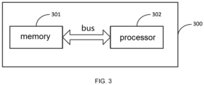
- an embodiment of the present disclosure provides a computer device 300 for executing the method for master-slave cooperative capacity expansion of mobile battery described in FIG. 1 .
- the device comprises a memory 301, a processor 302 connected to the memory 301 via a bus, and a computer program stored in the memory 301 and executable on the processor 302.
- the aforementioned processor 302 when executing the aforementioned computer program, implements the steps of the method for the master-slave cooperative capacity expansion of the mobile battery described above.
- the above mentioned memory 301 and processor 302 can be general-purpose memory and processor. No specific limitations are made herein.
- the processor 302 runs the computer program stored in the memory 301, it can execute the method for master-slave cooperative capacity expansion of the mobile battery described above.
- the embodiment of the present disclosure also provides a computer-readable storage medium, wherein the computer-readable storage medium stores a computer program.
- the computer program when executed by a processor, performs the steps of the method for the master-slave cooperative capacity expansion of the mobile battery described above.
- the storage medium can be a general-purpose storage medium, such as a removable disk, hard drive, etc.
- the computer program stored on the storage medium When executed, it can perform the method for master-slave cooperative capacity expansion of the mobile battery described above.
- the units illustrated as separate components can/cannot be physically separated, and the components displayed as units can/cannot be physical units, that is, they can be located in one place or distributed to a plurality of network units. Some or all of these units can be selected according to actual needs to achieve the objective of the embodiment solution.
- each functional unit in the embodiments of the present disclosure can be integrated into a single processing unit, each unit can be physically present separately, or two or more units can be integrated into a single unit.
- the functions When the functions are realized in the form of software function units and sold or used as independent products, they can be stored in a computer-readable storage medium.
- the essentials of the technical solution of the present disclosure or the part that contributes to the prior art or the part of the technical solution can be embodied in the form of a software product, wherein the computer software product is stored in a storage medium, including several instructions used to make a computer device (which can be a personal computer, a server, or a network device, etc.) execute all or part of the steps of the methods described in each embodiment of the present disclosure.
- the aforementioned storage media include a USB flash drive, mobile hard disk, read-only memory (ROM), random access memory (RAM), disk or CD, and other media that can store program code.
Landscapes
- Engineering & Computer Science (AREA)
- Power Engineering (AREA)
- Manufacturing & Machinery (AREA)
- Chemical & Material Sciences (AREA)
- Chemical Kinetics & Catalysis (AREA)
- Electrochemistry (AREA)
- General Chemical & Material Sciences (AREA)
- Business, Economics & Management (AREA)
- Emergency Management (AREA)
- Charge And Discharge Circuits For Batteries Or The Like (AREA)
- Secondary Cells (AREA)
- Protection Of Static Devices (AREA)
Applications Claiming Priority (2)
| Application Number | Priority Date | Filing Date | Title |
|---|---|---|---|
| CN202211351174.3A CN117996929A (zh) | 2022-10-31 | 2022-10-31 | 一种移动电池的主从联动扩容方法及装置 |
| PCT/CN2023/074139 WO2024093035A1 (zh) | 2022-10-31 | 2023-02-01 | 一种移动电池的主从联动扩容方法及装置 |
Publications (2)
| Publication Number | Publication Date |
|---|---|
| EP4386933A1 true EP4386933A1 (de) | 2024-06-19 |
| EP4386933A4 EP4386933A4 (de) | 2025-07-16 |
Family
ID=88372535
Family Applications (1)
| Application Number | Title | Priority Date | Filing Date |
|---|---|---|---|
| EP23771752.5A Pending EP4386933A4 (de) | 2022-10-31 | 2023-02-01 | Master-slave-verbindungskapazitätserweiterungsverfahren und -vorrichtung für mobile batterie |
Country Status (6)
| Country | Link |
|---|---|
| US (1) | US20250096585A1 (de) |
| EP (1) | EP4386933A4 (de) |
| JP (1) | JP7652926B2 (de) |
| CN (1) | CN117996929A (de) |
| AU (1) | AU2023233178B2 (de) |
| WO (1) | WO2024093035A1 (de) |
Family Cites Families (7)
| Publication number | Priority date | Publication date | Assignee | Title |
|---|---|---|---|---|
| JP2000228831A (ja) * | 1999-02-08 | 2000-08-15 | Hitachi Ltd | 組電池のばらつき補正方法 |
| CN106233566A (zh) * | 2014-03-28 | 2016-12-14 | 日本电气株式会社 | 蓄电系统和用于控制所述蓄电系统的放电的方法 |
| CN106026356A (zh) * | 2016-05-27 | 2016-10-12 | 东莞铭普光磁股份有限公司 | 一种实现电池扩容的方法 |
| CN107769279B (zh) * | 2016-08-18 | 2020-11-17 | 太普动力新能源(常熟)股份有限公司 | 电池并联搭接的控制方法 |
| US11605839B2 (en) * | 2020-02-10 | 2023-03-14 | Anduril Industries, Inc. | Battery system |
| CN111555393B (zh) * | 2020-05-19 | 2024-03-08 | 格力博(江苏)股份有限公司 | 一种多电池组件管理装置、控制方法以及电动工具 |
| CN112737018B (zh) * | 2020-12-24 | 2022-07-15 | 东莞新能安科技有限公司 | 电池包主从动态并机方法、用电设备及存储介质 |
-
2022
- 2022-10-31 CN CN202211351174.3A patent/CN117996929A/zh active Pending
-
2023
- 2023-02-01 WO PCT/CN2023/074139 patent/WO2024093035A1/zh not_active Ceased
- 2023-02-01 JP JP2023560872A patent/JP7652926B2/ja active Active
- 2023-02-01 EP EP23771752.5A patent/EP4386933A4/de active Pending
- 2023-02-01 US US18/289,772 patent/US20250096585A1/en active Pending
- 2023-02-01 AU AU2023233178A patent/AU2023233178B2/en not_active Expired - Fee Related
Also Published As
| Publication number | Publication date |
|---|---|
| AU2023233178A1 (en) | 2024-05-16 |
| EP4386933A4 (de) | 2025-07-16 |
| WO2024093035A1 (zh) | 2024-05-10 |
| JP7652926B2 (ja) | 2025-03-27 |
| AU2023233178B2 (en) | 2025-04-17 |
| US20250096585A1 (en) | 2025-03-20 |
| CN117996929A (zh) | 2024-05-07 |
| JP2024542335A (ja) | 2024-11-15 |
Similar Documents
| Publication | Publication Date | Title |
|---|---|---|
| CN115514064B (zh) | 一种用于锂电池电源系统的电池管理系统 | |
| TWI277268B (en) | Battery pack, battery protection processing apparatus, and startup control method of the battery protection processing apparatus | |
| CN102496991B (zh) | 一种后备式锂离子电池组管理方法及其管理系统 | |
| EP3288135B1 (de) | Ladesteuerungsvorrichtung und -verfahren für batteriepack | |
| KR102269113B1 (ko) | Ess 과전류 보호 방법 | |
| CN112737043A (zh) | 电源储能系统、电源储能系统的控制方法及装置 | |
| CN109617167A (zh) | 一种电池过放电警示方法、装置、电池及飞行器 | |
| US9300158B2 (en) | Method and apparatus for loading voltage thresholds from a battery for a device | |
| CN117713163A (zh) | 储能系统的控制方法、装置及储能系统 | |
| EP4386933A1 (de) | Master-slave-verbindungskapazitätserweiterungsverfahren und -vorrichtung für mobile batterie | |
| CN115291120B (zh) | 电池计量系统、电子设备及控制方法 | |
| CN114362349B (zh) | 一种充放电控制方法、系统、装置、电机设备及存储介质 | |
| CN110212602A (zh) | 一种充电控制方法及装置、计算机存储介质 | |
| EP4123867B1 (de) | Intelligente batterievorrichtung und elektronische vorrichtung dafür | |
| CN112994179B (zh) | 一种应用在园林工具的磷酸铁锂电池管理系统 | |
| CN112653231A (zh) | 一种电力终端的后备供电装置及方法 | |
| JP2017085684A (ja) | 電子機器 | |
| CN221308109U (zh) | 清洁机器人的识别电路和清洁机器人 | |
| CN213585273U (zh) | 一种地震观测电源状态自动监控及转换的电源电路 | |
| CN102104245A (zh) | 一种动力电池保护方法和系统 | |
| CN118810544A (zh) | 基于电池管理系统监控蓄电池的方法、装置及存储介质 | |
| CN121332830A (zh) | 电池包的防冲击电流控制方法、控制器、系统及存储介质 | |
| CN117767381A (zh) | 应用于储能系统的电池管理系统 | |
| CN121813621A (zh) | 储能电源的故障处理方法、储能电源及存储介质 | |
| CN119448528A (zh) | 一种配电自动化后备电源电池过放电自动激活方法及系统 |
Legal Events
| Date | Code | Title | Description |
|---|---|---|---|
| STAA | Information on the status of an ep patent application or granted ep patent |
Free format text: STATUS: UNKNOWN |
|
| STAA | Information on the status of an ep patent application or granted ep patent |
Free format text: STATUS: THE INTERNATIONAL PUBLICATION HAS BEEN MADE |
|
| PUAI | Public reference made under article 153(3) epc to a published international application that has entered the european phase |
Free format text: ORIGINAL CODE: 0009012 |
|
| STAA | Information on the status of an ep patent application or granted ep patent |
Free format text: STATUS: REQUEST FOR EXAMINATION WAS MADE |
|
| 17P | Request for examination filed |
Effective date: 20230925 |
|
| AK | Designated contracting states |
Kind code of ref document: A1 Designated state(s): AL AT BE BG CH CY CZ DE DK EE ES FI FR GB GR HR HU IE IS IT LI LT LU LV MC ME MK MT NL NO PL PT RO RS SE SI SK SM TR |
|
| REG | Reference to a national code |
Ref country code: DE Ref legal event code: R079 Free format text: PREVIOUS MAIN CLASS: H01M0010420000 Ipc: H02J0007000000 |
|
| STAA | Information on the status of an ep patent application or granted ep patent |
Free format text: STATUS: EXAMINATION IS IN PROGRESS |
|
| A4 | Supplementary search report drawn up and despatched |
Effective date: 20250617 |
|
| RIC1 | Information provided on ipc code assigned before grant |
Ipc: H02J 7/00 20060101AFI20250611BHEP Ipc: H01M 10/42 20060101ALI20250611BHEP Ipc: H02J 9/06 20060101ALN20250611BHEP |
|
| 17Q | First examination report despatched |
Effective date: 20250627 |
|
| DAV | Request for validation of the european patent (deleted) | ||
| DAX | Request for extension of the european patent (deleted) |