EP4385876A1 - Fahrradnabe, system, fahrrad und verfahren zur montage einer fahrradnabe - Google Patents
Fahrradnabe, system, fahrrad und verfahren zur montage einer fahrradnabe Download PDFInfo
- Publication number
- EP4385876A1 EP4385876A1 EP23213274.6A EP23213274A EP4385876A1 EP 4385876 A1 EP4385876 A1 EP 4385876A1 EP 23213274 A EP23213274 A EP 23213274A EP 4385876 A1 EP4385876 A1 EP 4385876A1
- Authority
- EP
- European Patent Office
- Prior art keywords
- hub
- coupling
- bicycle
- interface
- bicycle hub
- Prior art date
- Legal status (The legal status is an assumption and is not a legal conclusion. Google has not performed a legal analysis and makes no representation as to the accuracy of the status listed.)
- Granted
Links
Images


Classifications
-
- B—PERFORMING OPERATIONS; TRANSPORTING
- B62—LAND VEHICLES FOR TRAVELLING OTHERWISE THAN ON RAILS
- B62M—RIDER PROPULSION OF WHEELED VEHICLES OR SLEDGES; POWERED PROPULSION OF SLEDGES OR SINGLE-TRACK CYCLES; TRANSMISSIONS SPECIALLY ADAPTED FOR SUCH VEHICLES
- B62M6/00—Rider propulsion of wheeled vehicles with additional source of power, e.g. combustion engine or electric motor
- B62M6/40—Rider propelled cycles with auxiliary electric motor
- B62M6/60—Rider propelled cycles with auxiliary electric motor power-driven at axle parts
- B62M6/65—Rider propelled cycles with auxiliary electric motor power-driven at axle parts with axle and driving shaft arranged coaxially
-
- B—PERFORMING OPERATIONS; TRANSPORTING
- B62—LAND VEHICLES FOR TRAVELLING OTHERWISE THAN ON RAILS
- B62M—RIDER PROPULSION OF WHEELED VEHICLES OR SLEDGES; POWERED PROPULSION OF SLEDGES OR SINGLE-TRACK CYCLES; TRANSMISSIONS SPECIALLY ADAPTED FOR SUCH VEHICLES
- B62M6/00—Rider propulsion of wheeled vehicles with additional source of power, e.g. combustion engine or electric motor
- B62M6/40—Rider propelled cycles with auxiliary electric motor
- B62M6/60—Rider propelled cycles with auxiliary electric motor power-driven at axle parts
-
- B—PERFORMING OPERATIONS; TRANSPORTING
- B60—VEHICLES IN GENERAL
- B60L—PROPULSION OF ELECTRICALLY-PROPELLED VEHICLES; SUPPLYING ELECTRIC POWER FOR AUXILIARY EQUIPMENT OF ELECTRICALLY-PROPELLED VEHICLES; ELECTRODYNAMIC BRAKE SYSTEMS FOR VEHICLES IN GENERAL; MAGNETIC SUSPENSION OR LEVITATION FOR VEHICLES; MONITORING OPERATING VARIABLES OF ELECTRICALLY-PROPELLED VEHICLES; ELECTRIC SAFETY DEVICES FOR ELECTRICALLY-PROPELLED VEHICLES
- B60L50/00—Electric propulsion with power supplied within the vehicle
- B60L50/20—Electric propulsion with power supplied within the vehicle using propulsion power generated by humans or animals
-
- B—PERFORMING OPERATIONS; TRANSPORTING
- B62—LAND VEHICLES FOR TRAVELLING OTHERWISE THAN ON RAILS
- B62M—RIDER PROPULSION OF WHEELED VEHICLES OR SLEDGES; POWERED PROPULSION OF SLEDGES OR SINGLE-TRACK CYCLES; TRANSMISSIONS SPECIALLY ADAPTED FOR SUCH VEHICLES
- B62M6/00—Rider propulsion of wheeled vehicles with additional source of power, e.g. combustion engine or electric motor
- B62M6/80—Accessories, e.g. power sources; Arrangements thereof
-
- B—PERFORMING OPERATIONS; TRANSPORTING
- B60—VEHICLES IN GENERAL
- B60L—PROPULSION OF ELECTRICALLY-PROPELLED VEHICLES; SUPPLYING ELECTRIC POWER FOR AUXILIARY EQUIPMENT OF ELECTRICALLY-PROPELLED VEHICLES; ELECTRODYNAMIC BRAKE SYSTEMS FOR VEHICLES IN GENERAL; MAGNETIC SUSPENSION OR LEVITATION FOR VEHICLES; MONITORING OPERATING VARIABLES OF ELECTRICALLY-PROPELLED VEHICLES; ELECTRIC SAFETY DEVICES FOR ELECTRICALLY-PROPELLED VEHICLES
- B60L2200/00—Type of vehicles
- B60L2200/12—Bikes
-
- B—PERFORMING OPERATIONS; TRANSPORTING
- B62—LAND VEHICLES FOR TRAVELLING OTHERWISE THAN ON RAILS
- B62J—CYCLE SADDLES OR SEATS; AUXILIARY DEVICES OR ACCESSORIES SPECIALLY ADAPTED TO CYCLES AND NOT OTHERWISE PROVIDED FOR, e.g. ARTICLE CARRIERS OR CYCLE PROTECTORS
- B62J11/00—Supporting arrangements specially adapted for fastening specific devices to cycles, e.g. supports for attaching maps
- B62J11/10—Supporting arrangements specially adapted for fastening specific devices to cycles, e.g. supports for attaching maps for mechanical cables, hoses, pipes or electric wires, e.g. cable guides
Definitions
- a bicycle hub is specified.
- a system, a bicycle and a method for assembling a bicycle hub are specified.
- Bicycles are a cost-effective, easy-to-use and emission-free means of transport. They have also become popular as sports and fitness equipment, and types have been developed that are particularly suitable for different areas of application.
- One problem to be solved is to provide an improved bicycle hub, for example a bicycle hub that is particularly easy to assemble and/or that is particularly robust. Further problems to be solved are to provide a system with such a bicycle hub, a bicycle with a such a bicycle hub and a method for assembling such a bicycle hub.
- the bicycle hub is specified.
- the bicycle hub is, for example, a rear wheel bicycle hub.
- the bicycle hub can be a rear wheel hub drive.
- the bicycle hub has a hub element, a hub housing, an interface and an electrical component.
- the electrical component is electrically connected to the interface.
- the hub housing is mounted so as to be rotatable about an axis of rotation relative to the hub element in order to rotate together with a wheel of a bicycle during operation.
- the interface is arranged on an outer side of the bicycle hub and is rigidly connected to the hub element. The interface is offset radially outward relative to the axis of rotation.
- the interface is set up for an electrical and mechanical coupling of the bicycle hub to a coupling element in such a way that, on the one hand, an electrical connection is established from the coupling element to the electrical component via the coupling and, on the other hand, a relative rotation between the hub element and the coupling element is blocked via the coupling.
- the present invention is based, among other things, on the realization that a bicycle hub with an electrical component, for example an electric motor, requires an electrical connection on the one hand and a torque support connected to the bicycle hub on the other.
- the inventors had the idea of creating a functional combination of electrical connection and torque support.
- the interface In order to distribute the forces on the interface during torque transmission In order not to allow the interface to become too large, the interface is arranged radially away from the axis of rotation.
- the bicycle hub can then be electrically and mechanically coupled to a suitable (external) coupling element via the interface, whereby the coupling element is immovably connected to the hub element with respect to rotation about the axis of rotation. In this way, a torque acting on the hub element can be transferred to the coupling element. If the coupling element is then fixed to the bicycle frame of a bicycle, for example, the torque transmitted by the hub element can be diverted to the bicycle frame via the coupling element.
- Such a bicycle hub also enables the bicycle hub to be easily mounted on a bicycle frame, for example in combination with a thru axle. It also enables the electrical component to be easily connected electrically during assembly.
- the robust design of the interface which is rigidly connected to the hub element, means that the correspondingly designed coupling element can also be used as a torque support.
- the interface is protected against mechanical damage by its positioning and coupling with the coupling element.
- the interface also forms a robust electrical connection point on the bicycle hub and is protected against mechanical damage.
- the fact that the interface is rigidly connected to the hub element and is not implemented as a movable end of a cable hanging out of the bicycle hub reduces the risk of damage to the electrical connection to the electrical component during assembly and disassembly. With the help of the interface, which in this case has a dual function If this is fulfilled, a torque support in the complicated and sensitive area of the hub axle is avoided.
- the hub element and the hub housing are each robust components, for example made of metal and/or plastic.
- the hub element is, for example, rigidly connected to a hub axle of the bicycle hub or at least immovably connected/coupled to the hub axle in the direction of rotation.
- the hub element can be part of the hub axle, for example formed integrally with the hub axle, or it can be an element separate from the hub axle.
- the hub element can be formed integrally.
- the hub element forms a wall that at least partially covers the electrical component when viewed in the axial direction.
- the radius of the hub element is in particular larger than the average radius of the hub axle.
- the radius of the hub element is, for example, at least 50% or at least 75% of the maximum radius of the hub housing.
- an axial direction is understood to be a direction parallel to the axis of rotation.
- Radial directions are correspondingly directions perpendicular to the axis of rotation that intersect the axis of rotation.
- An azimuthal direction or rotation direction is a direction perpendicular to the radial direction and the axial direction.
- the hub housing is mounted so as to be rotatable relative to the hub element about the axis of rotation, in particular about the hub axle.
- the axis of rotation is understood to be the geometric or mathematical axis about which the hub housing rotates relative to the hub element and/or the hub axle.
- the hub axle is the mechanical component that is designed for a rigid connection to the frame of the bicycle.
- the hub shell completely surrounds the electrical component radially.
- the electrical component can be completely covered by the hub shell when viewed radially inwards.
- the bicycle hub has, for example, one or more rolling bearings. At least one rolling bearing can be implemented between the hub shell and the hub element. For example, the hub element and the hub shell then form the inner ring and outer ring of this rolling bearing.
- the bicycle hub can also have one or more freewheels and/or a receptacle for a gear ring.
- the hub shell is designed to rotate together with a wheel of the bicycle during operation.
- the hub shell has connection points for connecting to spokes of the bicycle, for example spoke flanges.
- the hub shell is designed to be rigidly connected to the (rear) wheel of the bicycle.
- the electrical component is electrically connected to the interface.
- a cable is routed from the interface to the electrical component.
- the cable can be completely surrounded radially by the hub shell.
- the electrical component and/or the cable cannot be seen from outside the bicycle hub, for example.
- the interface is arranged on an outer side of the bicycle hub and is rigidly connected to the hub element. This means that the interface is immovable relative to the hub element.
- the interface is arranged on the hub element or integrated into the hub element.
- the interface is preferably freely accessible from outside the bicycle hub.
- the interface is offset radially outward from the rotation axis.
- a center, in particular a geometric center, of the interface or the point of the interface closest to the rotation axis is at least 2 cm or at least 3 cm or at least 4 cm away from the rotation axis in the radial direction.
- the bicycle hub can be coupled to an (external) coupling element that matches the interface.
- the interface is designed for both an electrical and a mechanical coupling with the coupling element.
- the coupling element is immovably coupled/connected to the interface or the hub element, at least with respect to a movement along the direction of rotation. This means that when the coupling is established, a relative rotation between the coupling element and the interface or the hub element is blocked. This allows a torque acting on the hub element to be transferred to the external coupling element via the interface.
- “Blocked” here means that free rotation is blocked. A small relative movement due to play is possible.
- the mechanical coupling between the coupling element and the bicycle hub is a positive and/or non-positive connection, such as a plug connection. This connection can block relative rotation, but usually has a small amount of play.
- An electrical connection is also established between the external coupling element and the electrical component via the interface.
- the electrical connection is set up, for example, to supply power to the electrical component and/or to supply the electrical component with control signals.
- the coupling between the coupling element and the bicycle hub via the interface is preferably reversible.
- the interface is designed for a reversible coupling.
- the interface is formed by a first connector.
- the first connector can be plugged into a second connector.
- One of the first and second connectors is a female connector and the other is a male connector.
- the first connector is part of the bicycle hub and is rigidly connected to the hub element.
- the second connector is the external coupling element. The mechanical and electrical coupling is established by plugging the first and second connectors into one another.
- the first connector is designed to be plugged into the second connector in the axial direction, i.e. in a direction parallel to the axis of rotation.
- the two connectors are moved relative to one another in the axial direction, for example exclusively in the axial direction.
- the first connector is a socket in the bicycle hub, for example in the hub element.
- the interface is then formed, for example, by an exposed end of the socket.
- the first connector could also be a built-in plug in the bicycle hub, for example in the hub element. In this case, too, the interface would then be formed by the exposed end of the connector.
- the interface can also be implemented in a different way than by a connector.
- the interface could be an interface for a contactless electrical and mechanical coupling to the coupling element.
- the interface could be set up for a mechanical coupling through electromagnetic interaction.
- the interface could be the effective range of a magnet on the bicycle hub. If the coupling element also has a magnet, a mechanical coupling could be achieved through magnetic interaction.
- the interface could also be a fiber optic interface for the transmission of optical signals.
- optical signals for controlling the electrical component can be transmitted via the interface.
- the electrical component is an electric motor that is designed to rotate the hub shell relative to the hub element.
- the electric motor is in particular surrounded by the hub shell, for example, not visible from outside the bicycle hub.
- a rotor of the electric motor can be rigidly connected to the hub shell and a stator of the electric motor can be rigidly be connected to the hub element.
- the interface is arranged on an outer surface of the bicycle hub that is directed in the axial direction.
- the hub element forms a circular or annular outer surface of the bicycle hub.
- a normal to this outer surface runs, for example, parallel or essentially parallel, for example at an acute angle of at most 30°, to the axis of rotation.
- the interface can be arranged on this outer surface.
- the system is, for example, part of a bicycle or is intended to be assembled with other bicycle components to form a bicycle.
- the system comprises a bicycle hub according to one of the embodiments described here, a frame element and a coupling element.
- the bicycle hub is mechanically coupled to the frame element such that the hub shell is rotatable relative to the frame element and relative to the hub element about the axis of rotation.
- the coupling element is the interface is electrically and mechanically coupled to the bicycle hub.
- the coupling element is mechanically coupled to the frame element.
- the system has a bicycle hub according to one of the embodiments described here, all features disclosed in connection with the bicycle hub are also disclosed for the system and vice versa.
- the coupling element of the system is in particular the (external) coupling element described in connection with the bicycle hub.
- the mechanical coupling between the bicycle hub and the frame element which enables the hub shell to rotate, is a separate mechanical coupling that is not generated via the interface or the coupling element.
- the coupling between the bicycle hub and the frame element is, for example, a direct connection of the hub axle to the frame element.
- the hub axle and/or the hub element can be rigidly connected to the frame element.
- the frame member may be the bicycle frame or the frame member may be part of a bicycle frame or a part for a bicycle frame.
- the mechanical coupling between the coupling element and the bicycle hub and/or the mechanical coupling between the coupling element and the frame element are, for example, each a positive and/or non-positive connection.
- the coupling element engages in the frame element and/or in the bicycle hub.
- the coupling element transfers the torque from the bicycle hub to the frame element and thus acts as a torque transmission element.
- the coupling element is designed to be stable or rigid in order to transfer the torque. Apart from the coupling element, no other torque support is used to transfer the torque to the frame element.
- the mechanical coupling between the coupling element and the bicycle hub, which is established via the interface, together with the coupling between the coupling element and the frame element, is preferably designed such that the bicycle hub is in position is held relative to the frame element, even if the (separate) mechanical coupling between the bicycle hub and the frame element is released. This means that the mechanical coupling between the bicycle hub and the frame element established via the coupling element is strong enough to hold the bicycle hub in position even then.
- a connector housing extends continuously between the frame element and the bicycle hub and projects at least into both the frame element and the bicycle hub.
- the connector housing can be part of the coupling element or part of the bicycle hub.
- the plug housing surrounds electrical conductors of the electrical connection.
- the plug housing surrounds a plug contact and/or a socket contact of the electrical connection.
- the connector housing is formed to be stable enough to divert at least part of the torque acting on the hub element during operation of the bicycle hub to the frame element. This means that the connector housing withstands the forces that occur when diverting the torque and, for example, does not deform or only slightly and then in particular reversibly deforms when the torque is transmitted. For example, the connector housing is stable enough to withstand the entire torque acting on the to divert the torque acting on the hub element to the frame element.
- the plug housing is made of a hard plastic and/or metal.
- the coupling element is a plug.
- the plug housing is then, for example, the housing of the plug.
- the plug is an angle plug.
- the coupling element is guided through a hole in the frame element.
- a side wall of the frame element that delimits the hole forms a stop for the coupling element, with the aid of which the torque support is realized.
- the side wall delimits the hole in the direction of rotation. If the torque is transmitted to the coupling element, rotation of the coupling element about the axis of rotation is blocked by striking against the side wall of the hole.
- the interface overlaps with the hole in the viewing direction parallel to the axis of rotation. This means that when the coupling element is not guided through, the interface is at least partially visible or accessible through the hole in this viewing direction.
- the hole is formed, for example, round, in particular circular.
- the coupling element is accommodated in a recess in the frame element.
- a side wall of the frame element that delimits the recess forms a stop for the coupling element, with the aid of which the torque support is realized.
- the recess is not completely surrounded by the frame element on the sides.
- the recess is preferably also formed in such a way that the coupling element that absorbs the torque is prevented from rotating about the axis of rotation by striking the side wall that delimits the recess.
- the recess overlaps with the interface in the viewing direction parallel to the axis of rotation. This means that when the coupling element is not included, the interface is at least partially visible or accessible in this viewing direction in the area of the recess.
- the recess is formed, for example, square, in particular in the shape of an oblique parallelogram.
- the frame element forms three sides of the square recess and the recess is open on the fourth side, for example open towards the bottom.
- the coupling element is arranged at one end of a cable.
- the coupling element is electrically connected, for example, via the cable to a battery or accumulator and/or a control unit.
- the cable runs at least partially inside the frame element.
- the frame element can be formed as a hollow body.
- the cable then runs, for example, in a tunnel-shaped section of the frame element, for example along a longitudinal extension direction of the tunnel-shaped section.
- the cable starting from the coupling element, initially runs outside the frame element, is then guided through an opening in the frame element into the interior of the frame element and from then on runs at least partially inside the interior of the frame element.
- the transition point at which the cable transitions into the coupling element is arranged on a side of the frame element opposite the bicycle hub. This means that the frame element is arranged in a direction parallel to the axis of rotation between the transition point and the bicycle hub.
- the opening for the cable is, for example, a separate opening from the hole or recess for the coupling element. The opening can be spaced apart from the hole/recess.
- the bicycle is in particular an electric bicycle, for example a so-called Pedelec.
- the bicycle comprises a system according to one of the embodiments described here. Consequently, all features disclosed in connection with the system are also disclosed for the bicycle and vice versa.
- the bicycle hub forms, for example, a rear wheel hub drive.
- the bicycle comprises a control unit and/or a rechargeable battery which is electrically connected to the bicycle hub via the coupling established at the interface between the coupling element and the bicycle hub.
- the control unit can be used to transmit control signals to the electrical component in the bicycle hub, for example motor control signals.
- the method provides a bicycle hub according to one of the embodiments described here.
- a frame element and a coupling element are provided.
- the bicycle hub is mechanically coupled to the frame element in such a way that the hub housing is rotatable relative to the frame element and relative to the hub element about the axis of rotation.
- the coupling element is further electrically and mechanically coupled to the bicycle hub via the interface.
- the coupling element is further mechanically coupled to the frame element.
- an electrical connection is established from the coupling element to the electrical component using the electrical coupling established between the coupling element and the bicycle hub via the interface, and an electrical connection is established between the coupling element and the bicycle hub via the interface, and A torque support for the bicycle hub is realized using the mechanical coupling between the coupling element and the frame element.
- the mechanical coupling between the coupling element and the frame element is established, for example, by bringing the coupling element into positive engagement with the frame element.
- the coupling element is pushed from a side of the frame element facing away from the bicycle hub through the hole or recess into the frame element and then coupled to the bicycle hub via the interface.
- the coupling between the coupling element and the bicycle hub can also be achieved by bringing the coupling element into positive engagement with the bicycle hub at the interface.
- the step of mechanically coupling the bicycle hub to the frame element can take place before or after coupling the bicycle hub to the coupling element.
- the bicycle hub is screwed to the frame element or connected using a quick-release axle.
- the coupling can also take place using a thru axle.
- the step of coupling the coupling element to the frame element occurs simultaneously with the step of coupling the coupling element to the bicycle hub.
- a bicycle hub described here, a system described here, a bicycle described here and a method for assembling a bicycle hub described here are explained in more detail below with reference to drawings using exemplary embodiments.
- the same reference numerals indicate the same elements in the individual figures. However, references are not necessarily shown to scale; rather, individual elements may be shown exaggeratedly large for better understanding. If elements or components in the various figures have the same function, their description is not repeated for each of the following figures. For reasons of clarity, elements may not be provided with corresponding reference symbols in all figures.
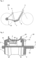
- FIG 1 shows schematically an electric bicycle 100 with a bicycle frame 6, which extends in the direction of a bottom bracket 7 and in the direction of a rear bicycle hub 10.
- the Bicycle hub 10 is electrically connected to a control unit 5 and a battery 8.
- Terms such as “front,” “rear,” “top,” “bottom,” “right,” “left,” “outside,” and “inside” refer to alignments or orientations of respective components as illustrated in the figures and as they are arranged in an operational state of the electric bicycle 100.
- the electric bicycle 100 typically has a front wheel and a rear wheel.
- An outside area refers to an area outside the electric bicycle 100.
- FIG 2 is the bicycle hub 10 of the Figure 1 shown in a two-part view, wherein a side view of the bicycle hub 10 is shown below the rotation axis A and a cross-sectional view is shown above the rotation axis A.
- the bicycle hub 10 comprises a hub axle 1a, a hub element 1 and a hub shell 2.
- the hub element 1 here forms a conversion which, together with the hub shell 2, surrounds an interior in which an electrical component 4 in the form of an electric motor 4 is arranged.
- the hub axle 1a, the hub element 1 and the hub housing 2 are each made of metal, for example.
- the hub element 1 is rigidly connected to the hub axle 1a, for example welded to the hub axle 1a or formed in one piece with it.
- the hub element 1 forms an outer surface of the bicycle hub which faces in the axial direction, parallel to the axis of rotation A 10, on which an interface 3 for a mechanical and electrical coupling to an external coupling element is arranged.
- the interface 3 is rigidly connected to the hub element 1.
- the hub housing 2 is rotatable about the rotation axis A and is arranged relative to the hub element 1.
- rolling bearings 21 are provided in the bicycle hub 10.
- the hub housing 2 is here, for example, coupled to a rotor 40 of the electric motor 4 and the hub axle 1a is coupled to a stator 41 of the electric motor 4.
- a transmission (not shown) can be connected between the hub housing 2 and the electric motor 4.
- the hub shell 2 comprises spoke flanges 20 for connection to spokes of a wheel, so that during operation the hub shell 2 rotates together with the rear wheel of the electric bicycle 100.
- the interface 3 is formed by a plug connector 31 in the form of a socket that is integrated or embedded in the hub element 1.
- the interface 3 is electrically connected to the electric motor 4. For example, electrical control signals for controlling or electrical current for supplying power to the electric motor 4 are transmitted to the bicycle hub 10 via the interface 3.
- Figure 3 shows a first position in an embodiment of the method for assembling a bicycle hub.
- the bicycle hub 10 of the Figure 2 provided and shown in a side view looking along the rotation axis A.
- the interface 3 or the bushing 31 is offset radially outwards with respect to the rotation axis A, for example by at least 3 cm.
- Figure 4 shows another position in which a frame element 6, in this case the rear part of the bicycle frame 6 of the Figure 1 , is provided.
- a passage 61 is provided for receiving the hub axle 1a of the bicycle hub 10.
- a hole 62 is provided in the frame element 6.
- the hole 62 runs completely through the frame element 6 in the axial direction.
- an opening 63 is provided in the frame element 6.
- the opening 63 forms an access to an inner, tunnel-shaped region of the frame element 6.
- a cable 33 protrudes from the opening 63.
- the cable 33 is guided in sections in the inner, tunnel-shaped region of the frame element 6.
- a connector 32 in the form of a plug 32 is provided at one end of the part of the cable 33 protruding from the frame element 6.
- FIG 5 a position in the process in which the bicycle hub 10 of the Figures 2 and 3 is mechanically coupled to the frame element 6 by guiding the hub axle 1a through the passage 61 and rigidly connecting it to the frame element 6. It can also be seen that the bicycle hub 10 is aligned such that, in the direction shown, parallel to the axis of rotation A, the interface 3 of the bicycle hub 10 overlaps with the hole 62 in the frame element 6. The interface 3 is visible through the hole 62 and accessible via the hole 62.
- a position is shown in another embodiment of the method for assembling a bicycle hub 10.
- the recess 64 is on the lower part of the frame element 6 and has an oblique parallelogram-shaped cross-section in the plan view shown.
- the plug 32 has an oblique parallelogram-shaped cross-section in the plan view for a positive engagement in the recess 64.
- the plug 32 is received in the recess 64 and plugged into the socket 31 of the bicycle hub 10, a torque exerted on the hub element 1 is transmitted to the plug 32 during operation of the electric motor 4. This transfers the torque to the frame element 6 through the positive engagement in the recess 64.
- the recess 64 and the plug 32 are coordinated with one another in such a way that when they engage with one another, rotation of the plug 32 about the rotation axis A relative to the frame element 6 is blocked.
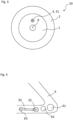
- FIG. 9 An embodiment of the coupling element 32 is shown in a side view. This is a plug 32, for example the one of the Figures 5 and 6 . Plug 32 is an angled plug.
- Figure 10 shows an embodiment of the system in which the connector 32 of the Figure 9 through a hole 62 or a recess 64 in the frame element 6 and is mechanically and electrically coupled to the bicycle hub 10 via the interface 3.
- the interface 3 of the bicycle hub 10 is again formed by a bushing 31 of the bicycle hub 10.
- the bushing housing 310 is formed by the hub element 1.
- the Socket housing 310 surrounds the socket contact 311 and the socket insert 312 of socket 31.
- the plug 32 has a plug contact 321 and a plug insert 322.
- the plug contact 321 and the plug insert 322 are surrounded by a plug housing 320.
- the plug housing 320 is sturdily formed, for example from metal or hard plastic.
- the plug housing 320 is plugged into the socket 31.
- the plug contact 321 is plugged into the socket contact 311, thereby establishing the electrical connection.
- the plug housing 320 extends continuously from the frame element 6 into the hub element 1 and projects into both the frame element 6 and the hub element 1.
- the torque exerted on the hub element 1 is then predominantly transmitted to the frame element 6 via the stable connector housing 320.
Landscapes
- Engineering & Computer Science (AREA)
- Chemical & Material Sciences (AREA)
- Combustion & Propulsion (AREA)
- Transportation (AREA)
- Mechanical Engineering (AREA)
- Power Engineering (AREA)
- Axle Suspensions And Sidecars For Cycles (AREA)
- Connection Of Motors, Electrical Generators, Mechanical Devices, And The Like (AREA)
Abstract
Description
- Es wird eine Fahrradnabe angegeben. Darüber hinaus werden ein System, ein Fahrrad und ein Verfahren zur Montage einer Fahrradnabe angegeben.
- Fahrräder realisieren kostengünstige, leicht zu handhabende und emissionsfreie Fortbewegungsmittel. Sie haben auch als Sport- beziehungsweise Fitnessgeräte Verbreitung gefunden, und es haben sich für unterschiedliche Einsatzfelder besonders geeignete Typen herausgebildet.
- In den letzten Jahren wächst die Begeisterung für Elektrofahrräder, insbesondere sogenannte "Pedelecs", und das auch trotz der für Fahrräder hohen Gewichte und Preise. Potenzielle Kunden sind nicht nur ältere, weniger konditionsstarke oder von sportlichen Ambitionen freie Radfahrer, sondern auch sportliche, jüngere Fahrer, sei es zur Nutzung auf dem Arbeitsweg oder wegen der Möglichkeit, mit ihnen ohne Überbeanspruchung der eigenen Physis den Aktionsradius zu erweitern und/oder die Reisegeschwindigkeit zu erhöhen. Gerade bei Mountainbikern scheint das Interesse an elektrisch unterstützten Mountainbikes zu wachsen.
- Eine zu lösende Aufgabe besteht darin, eine verbesserte Fahrradnabe bereitzustellen, beispielsweise eine Fahrradnabe, die besonders einfach zu montieren ist und/oder die besonders robust ist. Weitere zu lösende Aufgaben bestehen darin, ein System mit einer solchen Fahrradnabe, ein Fahrrad mit einer solchen Fahrradnabe und ein Verfahren zur Montage einer solchen Fahrradnabe anzugeben.
- Zunächst wird die Fahrradnabe angegeben. Die Fahrradnabe ist beispielsweise eine Hinterradfahrradnabe. Insbesondere kann die Fahrradnarbe ein Hinterradnabenantrieb sein.
- In mindestens einer Ausführungsform weist die Fahrradnabe ein Nabenelement, ein Nabengehäuse, eine Schnittstelle und ein elektrisches Bauteil auf. Das elektrische Bauteil ist mit der Schnittstelle elektrisch verbunden. Das Nabengehäuse ist relativ zum Nabenelement rotierbar um eine Rotationsachse gelagert, um im Betrieb zusammen mit einem Rad eines Fahrrads zu rotieren. Die Schnittstelle ist an einer Außenseite der Fahrradnabe angeordnet und starr mit dem Nabenelement verbunden. Die Schnittstelle ist gegenüber der Rotationsachse radial nach außen versetzt. Ferner ist die Schnittstelle für eine elektrische und mechanische Kopplung der Fahrradnabe mit einem Kopplungselement eingerichtet, derart, dass über die Kopplung einerseits eine elektrische Verbindung vom Kopplungselement zum elektrischen Bauteil hergestellt ist und andererseits über die Kopplung eine relative Rotation zwischen dem Nabenelement und dem Kopplungselement blockiert ist.
- Der vorliegenden Erfindung liegt unter anderem die Erkenntnis zu Grunde, dass eine Fahrradnabe mit elektrischem Bauteil, zum Beispiel einem Elektromotor, einerseits eine elektrische Verbindung und andererseits eine mit der Fahrradnabe verbundene Drehmomentabstützung benötigt. Die Erfinder hatten die Idee, eine funktionale Kombination aus elektrischer Verbindung und Drehmomentabstützung zu realisieren. Um die Kräfte auf die Schnittstelle bei der Drehmomentübertragung nicht zu groß werden zu lassen, wird die Schnittstelle radial entfernt von der Rotationsachse angeordnet. Über die Schnittstelle kann dann die Fahrradnabe mit einem passenden (externen) Kopplungselement elektrisch und mechanisch gekoppelt werden, wobei das Kopplungselement in Bezug auf eine Rotation um die Rotationsachse unbeweglich mit dem Nabenelement verbunden ist. So kann ein auf das Nabenelement wirkendes Drehmoment auf das Kopplungselement übertragen werden. Wird das Kopplungselement dann beispielsweise am Fahrradrahmen eines Fahrrads fixiert, kann über das Kopplungselement das von dem Nabenelement übertragende Drehmoment auf den Fahrradrahmen abgeleitet werden.
- Eine solche Fahrradnabe ermöglicht zudem eine einfache Montage der Fahrradnabe an einem Fahrradrahmen, zum Beispiel auch in Kombination mit einer Steckachse. Auch ein einfaches elektrisches Verbinden des elektrischen Bauteils während der Montage ist ermöglicht. Durch die robuste, starr mit dem Nabenelement verbundene Ausführung der Schnittstelle kann das entsprechend konstruierte Kopplungselement gleichzeitig als Drehmomentstütze eingesetzt werden. Die Schnittstelle ist durch ihre Positionierung und Kopplung mit dem Kopplungselement gegen mechanische Schäden geschützt. Die Schnittstelle bildet außerdem eine robuste elektrische Verbindungsstelle an der Fahrradnabe und ist gegen mechanische Schäden geschützt. Insbesondere dadurch, dass die Schnittstelle starr mit dem Nabenelement verbunden ist und nicht als bewegliches Ende eines aus der Fahrradnabe heraushängenden Kabels realisiert ist, ist die Gefahr einer Beschädigung der elektrischen Verbindung zum elektrischen Bauteil während der Montage und Demontage reduziert. Mithilfe der Schnittstelle, die vorliegend eine Doppelfunktion erfüllt, wird eine Drehmomentstütze im komplizierten und empfindlichen Bereich der Nabenachse vermieden.
- Das Nabenelement und das Nabengehäuse sind jeweils robuste Bauteile, zum Beispiel aus Metall und/oder Kunststoff. Das Nabenelement ist zum Beispiel starr mit einer Nabenachse der Fahrradnabe verbunden oder zumindest in Rotationsrichtung unbeweglich mit der Nabenachse verbunden/gekoppelt. Das Nabenelement kann ein Teil der Nabenachse sein, zum Beispiel einstückig mit der Nabenachse gebildet sein, oder es kann ein von der Nabenachse separates Element sein. Das Nabenelement kann einstückig gebildet sein. Beispielsweise bildet das Nabenelement eine Wandung, die das elektrische Bauteil bei Blickrichtung in axialer Richtung zumindest teilweise überdeckt. Der Radius des Nabenelements ist insbesondere größer als der mittlere Radius der Nabenachse. Der Radius des Nabenelements beträgt beispielsweise zumindest 50 % oder zumindest 75 % des maximalen Radius des Nabengehäuses.
- Hier und im Folgenden wird unter einer axialen Richtung eine Richtung parallel zur Rotationsachse verstanden. Radiale Richtungen sind entsprechend Richtungen senkrecht zur Rotationsachse, die die Rotationsachse schneiden. Eine azimutale Richtung oder Rotationsrichtung ist eine Richtung senkrecht zur radialen Richtung und zur axialen Richtung.
- Das Nabengehäuse ist relativ zum Nabenelement rotierbar um die Rotationsachse, insbesondere um die Nabenachse, gelagert. Vorliegend wird unter der Rotationsachse die geometrische beziehungsweise mathematische Achse verstanden, um die das Nabengehäuse relativ zum Nabenelement und/oder zur Nabenachse rotiert. Die Nabenachse ist das mechanische Bauteil, das für eine starre Verbindung zum Rahmen des Fahrrads eingerichtet ist. Beispielsweise umgibt das Nabengehäuse das elektrische Bauteil radial vollständig. Insbesondere kann das elektrische Bauteil bei Blickrichtung radial nach innen vollständig von dem Nabengehäuse überdeckt sein.
- Um das Rotieren des Nabengehäuses relativ zum Nabenelement zu ermöglichen, weist die Fahrradnabe zum Beispiel ein oder mehrere Wälzlager auf. Zumindest ein Wälzlager kann zwischen dem Nabengehäuse und dem Nabenelement realisiert sein. Zum Beispiel bilden das Nabenelement und das Nabengehäuse dann Innenring und Außenring dieses Wälzlagers. Weiter kann die Fahrradnabe einen oder mehrere Freiläufe und/oder eine Aufnahme für einen Zahnkranz aufweisen.
- Das Nabengehäuse ist dazu eingerichtet, im Betrieb zusammen mit einem Rad des Fahrrads zu rotieren. Zum Beispiel weist das Nabengehäuse Verbindungsstellen für die Verbindung mit Speichen des Fahrrads auf, zum Beispiel Speichenflansche. Insbesondere ist das Nabengehäuse dazu eingerichtet, starr mit dem (Hinter-)Rad des Fahrrads verbunden zu werden.
- Das elektrische Bauteil ist mit der Schnittstelle elektrisch verbunden. Beispielsweise ist ein Kabel von der Schnittstelle zum elektrischen Bauteil geführt. Das Kabel kann radial vollständig von dem Nabengehäuse umgeben sein. Von außerhalb der Fahrradnabe sind das elektrische Bauteil und/oder das Kabel beispielsweise nicht einsehbar.
- Die Schnittstelle ist an einer Außenseite der Fahrradnabe angeordnet und starr mit dem Nabenelement verbunden. Das heißt, die Schnittstelle ist unbeweglich relativ zum Nabenelement. Beispielsweise ist die Schnittstelle an dem Nabenelement angeordnet oder in das Nabenelement integriert.
- Im unmontierten Zustand der Fahrradnabe ist die Schnittstelle von außerhalb der Fahrradnabe bevorzugt frei zugänglich.
- Die Schnittstelle ist gegenüber der Rotationsachse radial nach außen versetzt. Beispielsweise ist ein Zentrum, insbesondere ein geometrisches Zentrum, der Schnittstelle oder der der Rotationsachse nächste Punkt der Schnittstelle zumindest 2 cm oder zumindest 3 cm oder zumindest 4 cm in radialer Richtung von der Rotationsachse entfernt.
- An der Schnittstelle ist die Fahrradnabe mit einem zur Schnittstelle passenden (externen) Kopplungselement koppelbar. Die Schnittstelle ist sowohl für eine elektrische als auch eine mechanische Kopplung mit dem Kopplungselement eingerichtet. Wenn die Kopplung zwischen dem externen Kopplungselement und der Fahrradnabe über die Schnittstelle hergestellt ist, ist das Kopplungselement zumindest in Bezug auf eine Bewegung entlang der Rotationsrichtung unbeweglich mit der Schnittstelle beziehungsweise dem Nabenelement gekoppelt/verbunden. Das heißt, bei hergestellter Kopplung ist eine relative Rotation zwischen dem Kopplungselement und der Schnittstelle beziehungsweise dem Nabenelement blockiert. Dadurch kann ein auf das Nabenelement wirkendes Drehmoment über die Schnittstelle auf das externe Kopplungselement übertragen werden.
- "Blockiert" bedeutet hierbei, dass eine freie Rotation blockiert ist. Eine geringe, relative Bewegung aufgrund von Spiel ist möglich. Zum Beispiel ist die mechanische Kopplung zwischen dem Kopplungselement und der Fahrradnabe eine formschlüssige und/oder kraftschlüssige Verbindung, wie eine Steckverbindung. Diese Verbindung kann die relative Rotation blockieren, hat aber meist ein geringes Spiel.
- Über die Schnittstelle ist zudem eine elektrische Verbindung zwischen dem externen Kopplungselement und dem elektrischen Bauteil eingerichtet. Die elektrische Verbindung ist zum Beispiel zur Stromversorgung des elektrischen Bauteils und/oder für die Versorgung des elektrischen Bauteils mit Steuersignalen eingerichtet.
- Die Kopplung zwischen dem Kopplungselement und der Fahrradnabe über die Schnittstelle ist bevorzugt reversibel. Anders ausgedrückt, ist die Schnittstelle für eine reversible Kopplung eingerichtet.
- Gemäß zumindest einer Ausführungsform ist die Schnittstelle durch einen ersten Steckverbinder gebildet. Der erste Steckverbinder ist mit einem zweiten Steckverbinder ineinandersteckbar. Einer des ersten und zweiten Steckverbinders ist ein weiblicher Steckverbinder und der andere ein männlicher Steckverbinder.
- Der erste Steckverbinder ist also Teil der Fahrradnabe und insbesondere starr mit dem Nabenelement verbunden. Der zweite Steckverbinder ist das externe Kopplungselement. Durch Ineinanderstecken des ersten und zweiten Steckverbinders wird die mechanische und elektrische Kopplung hergestellt.
- Gemäß zumindest einer Ausführungsform ist der erste Steckverbinder für ein Ineinanderstecken mit dem zweiten Steckverbinder in axialer Richtung, das heißt in Richtung parallel zur Rotationsachse, eingerichtet. Anders ausgedrückt werden während des Ineinandersteckens die beiden Steckverbinder in axiale Richtung, zum Beispiel ausschließlich in axiale Richtung, relativ zueinander bewegt.
- Gemäß zumindest einer Ausführungsform ist der erste Steckverbinder eine Buchse in der Fahrradnabe, zum Beispiel in dem Nabenelement. Die Schnittstelle ist dann zum Beispiel durch ein freiliegendes Ende der Buchse gebildet. Alternativ könnte der erste Steckverbinder auch ein Einbaustecker in der Fahrradnabe, zum Beispiel in dem Nabenelement, sein. Auch in diesem Fall wäre die Schnittstelle dann durch das freiliegende Ende des Steckverbinders gebildet.
- Die Schnittstelle kann aber auch anders als durch einen Steckverbinder realisiert sein. Zum Beispiel könnte die Schnittstelle eine Schnittstelle für eine kontaktlose elektrische und mechanische Kopplung zum Kopplungselement sein. Die Schnittstelle könnte für eine mechanische Kopplung durch elektromagnetische Wechselwirkung eingerichtet sein. Insbesondere könnte die Schnittstelle der Wirkbereich eines Magneten der Fahrradnabe sein. Wenn das Kopplungselement auch einen Magneten aufweist, könnte eine mechanische Kopplung durch magnetische Wechselwirkung erreicht werden.
- Die Schnittstelle könnte auch eine LWL-Schnittstelle für die Übertragung von optischen Signalen sein. Zum Beispiel können optische Signale für die Steuerung des elektrischen Bauteils über die Schnittstelle übertragen werden.
- Gemäß zumindest einer Ausführungsform ist das elektrische Bauteil ein Elektromotor, der dazu eingerichtet ist, das Nabengehäuse relativ zum Nabenelement zu rotieren. Der Elektromotor ist insbesondere vom Nabengehäuse umgeben, zum Beispiel von außerhalb der Fahrradnabe nicht einsehbar. Ein Rotor des Elektromotors kann starr mit dem Nabengehäuse verbunden sein und ein Stator des Elektromotors kann starr mit dem Nabenelement verbunden sein. Beim Betrieb des Elektromotors wird neben dem auf das Nabengehäuse übertragenen Drehmoment ein (unerwünschtes) Drehmoment auf das Nabenelement übertragen, das dann beispielsweise auf das an der Schnittstelle gekoppelte Kopplungselement übertragen wird.
- Die Fahrradnabe kann weiter ein Getriebe, wie ein Planetengetriebe, umfassen, um das von dem Elektromotor erzeugte Drehmoment auf das Nabengehäuse zu übertragen.
- Gemäß zumindest einer Ausführungsform ist die Schnittstelle an einer in axialer Richtung gerichteten Außenfläche der Fahrradnabe angeordnet. Beispielsweise bildet das Nabenelement eine kreisförmige oder ringförmige Außenfläche der Fahrradnabe. Eine Normale auf diese Außenfläche verläuft zum Beispiel parallel oder im Wesentlichen parallel, beispielsweise in einem spitzen Winkel von höchstens 30°, zur Rotationsachse. An dieser Außenfläche kann die Schnittstelle angeordnet sein.
- Als nächstes wird das System angegeben. Das System ist beispielsweise ein Teil eines Fahrrads oder ist dazu vorgesehen, mit weiteren Fahrradkomponenten zu einem Fahrrad zusammengebaut zu werden.
- In mindestens einer Ausführungsform umfasst das System eine Fahrradnabe nach einem der hier beschriebenen Ausführungsformen, ein Rahmenelement und ein Kopplungselement. Die Fahrradnabe ist mit dem Rahmenelement derart mechanisch gekoppelt, dass das Nabengehäuse relativ zum Rahmenelement und relativ zum Nabenelement um die Rotationsachse rotierbar ist. Das Kopplungselement ist über die Schnittstelle elektrisch und mechanisch mit der Fahrradnabe gekoppelt. Außerdem ist das Kopplungselement mit dem Rahmenelement mechanisch gekoppelt. Mithilfe der über die Schnittstelle hergestellten elektrischen Kopplung zwischen dem Kopplungselement und der Fahrradnabe ist eine elektrische Verbindung vom Kopplungselement zum elektrischen Bauteil hergestellt. Zudem ist mithilfe der über die Schnittstelle hergestellten mechanischen Kopplung zwischen dem Kopplungselement und der Fahrradnabe und mithilfe der mechanischen Kopplung zwischen dem Kopplungselement und dem Rahmenelement eine Drehmomentstütze für die Fahrradnabe realisiert.
- Da das System eine Fahrradnabe nach einer der hier beschriebenen Ausführungsformen aufweist, sind alle im Zusammenhang mit der Fahrradnabe offenbarten Merkmale auch für das System offenbart und umgekehrt. Bei dem Kopplungselement des Systems handelt es sich insbesondere um das im Zusammenhang mit der Fahrradnabe beschriebene (externe) Kopplungselement.
- Die mechanische Kopplung zwischen der Fahrradnabe und dem Rahmenelement, die ein Rotieren des Nabengehäuses ermöglicht, ist eine separate mechanische Kopplung, die nicht über die Schnittstelle beziehungsweise das Kopplungselement erzeugt wird. Die Kopplung zwischen der Fahrradnabe und dem Rahmenelement ist beispielsweise eine direkte Verbindung der Nabenachse mit dem Rahmenelement. Insbesondere können die Nabenachse und/oder das Nabenelement starr mit dem Rahmenelement verbunden sein.
- Das Rahmenelement kann der Fahrradrahmen sein oder das Rahmenelement kann Teil eines Fahrradrahmens oder ein Teil für einen Fahrradrahmen sein.
- Die mechanische Kopplung zwischen dem Kopplungselement und der Fahrradnabe und/oder die mechanische Kopplung zwischen dem Kopplungselement und dem Rahmenelement sind beispielsweise jeweils eine formschlüssige und/oder kraftschlüssige Verbindung. Zum Beispiel greift das Kopplungselement in das Rahmenelement und/oder in die Fahrradnabe ein.
- Durch die mechanische Kopplung zwischen dem Kopplungselement und der Fahrradnabe wird ein im Betrieb auf das Nabenelement wirkendes Drehmoment auf das Kopplungselement übertragen. Durch die mechanische Kopplung zwischen dem Kopplungselement und dem Rahmenelement wird dann das Drehmoment vom Kopplungselement auf das Rahmenelement übertragen, sodass das Drehmoment insgesamt auf das Rahmenelement abgeleitet wird.
- Anders ausgedrückt überträgt das Kopplungselement also das Drehmoment von der Fahrradnabe auf das Rahmenelement und wirkt somit als Drehmomentübertragungselement. Das Kopplungselement ist entsprechend stabil beziehungsweise steif ausgebildet, um das Drehmoment zu übertragen. Außer dem Kopplungselement wird beispielsweise keine weitere Drehmomentstütze zur Ableitung des Drehmoments auf das Rahmenelement verwendet.
- Die über die Schnittstelle hergestellte mechanische Kopplung zwischen dem Kopplungselement und der Fahrradnabe zusammen mit der Kopplung zwischen Kopplungselement und Rahmenelement ist bevorzugt so ausgeführt, dass die Fahrradnabe in Position relativ zum Rahmenelement gehalten wird, auch wenn die (separate) mechanische Kopplung zwischen der Fahrradnabe und dem Rahmenelement gelöst ist. Das heißt, die über das Kopplungselement hergestellte mechanische Kopplung zwischen Fahrradnabe und Rahmenelement ist stark genug, um die Fahrradnabe auch dann in Position zu halten.
- Gemäß zumindest einer Ausführungsform ist das Kopplungselement ein Steckverbinder und die mechanische und elektrische Kopplung zwischen dem Kopplungselement und der Fahrradnabe eine Steckverbindung.
- Gemäß zumindest einer Ausführungsform erstreckt sich ein Steckergehäuse zusammenhängend zwischen dem Rahmenelement und der Fahrradnabe und ragt sowohl in das Rahmenelement als auch in die Fahrradnabe zumindest hinein. Das Steckergehäuse kann Teil des Kopplungselements oder Teil der Fahrradnabe sein.
- Gemäß zumindest einer Ausführungsform umgibt das Steckergehäuse elektrische Leiter der elektrischen Verbindung. Zum Beispiel umgibt das Steckergehäuse einen Steckerkontakt und/oder einen Buchsenkontakt der elektrischen Verbindung.
- Gemäß zumindest einer Ausführungsform ist das Steckergehäuse stabil genug gebildet, um zumindest einen Teil des beim Betrieb der Fahrradnabe auf das Nabenelement wirkenden Drehmoments auf das Rahmenelement abzuleiten. Das heißt, das Steckergehäuse hält den Kräften, die beim Ableiten des Drehmoments auftreten, stand und verformt sich beim Übertragen des Drehmoments beispielsweise nicht oder nur geringfügig und dann insbesondere reversibel. Zum Beispiel ist das Steckergehäuse stabil genug, um das gesamte auf das Nabenelement wirkende Drehmoment auf das Rahmenelement abzuleiten.
- Gemäß zumindest einer Ausführungsform ist das Steckergehäuse aus einem Hartplastik und/oder Metall gebildet.
- Gemäß zumindest einer Ausführungsform ist das Kopplungselement ein Stecker. Das Steckergehäuse ist dann beispielsweise das Gehäuse des Steckers.
- Gemäß zumindest einer Ausführungsform ist der Stecker ein Winkelstecker.
- Gemäß zumindest einer Ausführungsform ist das Kopplungselement durch ein Loch im Rahmenelement geführt. Eine das Loch begrenzende Seitenwand des Rahmenelements bildet einen Anschlag für das Kopplungselement, mit Hilfe dessen die Drehmomentstütze realisiert ist. Insbesondere begrenzt die Seitenwand das Loch also in Rotationsrichtung. Wird das Drehmoment auf das Kopplungselement übertragen, so wird eine Rotation des Kopplungselements um die Rotationsachse durch das Anschlagen gegen die Seitenwand des Lochs blockiert.
- Gemäß zumindest einer Ausführungsform überlappt, in Blickrichtung parallel zur Rotationsachse, die Schnittstelle mit dem Loch. Das heißt, bei nicht hindurchgeführtem Kopplungselement ist die Schnittstelle in dieser Blickrichtung durch das Loch hindurch zumindest teilweise einsehbar oder zugänglich. In der beschriebenen Blickrichtung ist das Loch beispielsweise rund, insbesondere kreisförmig, gebildet.
- Gemäß zumindest einer Ausführungsform ist das Kopplungselement in eine Ausnehmung des Rahmenelements aufgenommen. Eine die Ausnehmung begrenzende Seitenwand des Rahmenelements bildet einen Anschlag für das Kopplungselement, mit Hilfe dessen die Drehmomentstütze realisiert ist. Im Unterschied zu dem Loch ist die Ausnehmung seitlich nicht vollständig von dem Rahmenelement umgeben. Eine solche Ausnehmung kann besonders einfach realisiert werden, ohne die Stabilität des Rahmenelements zu beeinflussen. Im Übrigen ist die Ausnehmung aber bevorzugt auch so gebildet, dass das das Drehmoment aufnehmende Kopplungselement durch Anschlagen an die die Ausnehmung begrenzende Seitenwand an einer Rotation um die Rotationsachse gehindert ist.
- Gemäß zumindest einer Ausführungsform überlappt in Blickrichtung parallel zur Rotationsachse die Ausnehmung mit der Schnittstelle. Das heißt, bei nicht aufgenommenem Kopplungselement ist die Schnittstelle in dieser Blickrichtung im Bereich der Ausnehmung zumindest teilweise einsehbar oder zugänglich. In der beschriebenen Blickrichtung ist die Ausnehmung beispielsweise viereckig, insbesondere schiefwinklig parallelogrammförmig, gebildet. Zum Beispiel bildet das Rahmenelement drei Seiten der viereckigen Ausnehmung und an der vierten Seite ist die Ausnehmung offen, zum Beispiel nach unten hin offen.
- Gemäß zumindest einer Ausführungsform ist das Kopplungselement an einem Ende eines Kabels angeordnet. Das Kopplungselement ist beispielsweise über das Kabel mit einer Batterie beziehungsweise einem Akkumulator und/oder einer Steuereinheit elektrisch verbunden.
- Gemäß zumindest einer Ausführungsform verläuft das Kabel zumindest abschnittsweise im Inneren des Rahmenelements. Insbesondere kann das Rahmenelement als Hohlkörper gebildet sein. Das Kabel verläuft dann zum Beispiel in einem tunnelförmigen Abschnitt des Rahmenelements, zum Beispiel entlang einer Längserstreckungsrichtung des tunnelförmigen Abschnitts.
- Gemäß zumindest einer Ausführungsform verläuft das Kabel ausgehend vom Kopplungselement zunächst außerhalb des Rahmenelements, ist dann durch eine Öffnung im Rahmenelement ins Innere des Rahmenelements geführt und verläuft von da an zumindest abschnittsweise im Inneren des Rahmenelements. Zum Beispiel ist die Übergangsstelle, an der das Kabel in das Kopplungselement übergeht, auf einer der Fahrradnabe gegenüberliegenden Seite des Rahmenelements angeordnet. Das heißt, das Rahmenelement ist in Richtung parallel zur Rotationsachse zwischen der Übergangsstelle und der Fahrradnabe angeordnet. Die Öffnung für das Kabel ist zum Beispiel eine von dem Loch oder der Ausnehmung für das Kopplungselement separate Öffnung. Die Öffnung kann von dem Loch/der Ausnehmung beabstandet sein.
- Als nächstes wird das Fahrrad angegeben. Bei dem Fahrrad handelt es sich insbesondere um ein Elektrofahrrad, zum Beispiel um ein so genanntes Pedelec.
- In mindestens einer Ausführungsform umfasst das Fahrrad ein System nach einem der hier beschriebenen Ausführungsformen. Folglich sind alle im Zusammenhang mit dem System offenbarten Merkmale auch für das Fahrrad offenbart und umgekehrt. Die Fahrradnabe bildet zum Beispiel einen Hinterradnabenantrieb.
- Gemäß zumindest einer Ausführungsform umfasst das Fahrrad eine Steuereinheit und/oder einen Akkumulator, die über die an der Schnittstelle hergestellte Kopplung zwischen dem Kopplungselement und der Fahrradnabe elektrisch mit der Fahrradnabe verbunden ist.
- Über die Steuereinheit können beispielsweise Steuersignale an das elektrische Bauteil in der Fahrradnabe übertragen werden, zum Beispiel Motorsteuersignale.
- Als nächstes wird das Verfahren zur Montage einer Fahrradnabe angegeben. Durch das Verfahren kann beispielsweise das hier beschriebene System hergestellt werden. Alle im Zusammenhang mit dem System offenbarten Merkmale sind daher auch für das Verfahren offenbart und umgekehrt.
- In mindestens einer Ausführungsform wird bei dem Verfahren eine Fahrradnabe nach einem der hier beschriebenen Ausführungsformen bereitgestellt. Außerdem werden ein Rahmenelement und ein Kopplungselement bereitgestellt. In einem nächsten Schritt wird die Fahrradnabe mit dem Rahmenelement derart mechanisch gekoppelt, dass das Nabengehäuse relativ zum Rahmenelement und relativ zum Nabenelement um die Rotationsachse rotierbar ist. Weiter wird das Kopplungselement elektrisch und mechanisch über die Schnittstelle mit der Fahrradnabe gekoppelt. Ferner wird das Kopplungselement mit dem Rahmenelement mechanisch gekoppelt. Dabei wird mithilfe der über die Schnittstelle hergestellten elektrischen Kopplung zwischen dem Kopplungselement und der Fahrradnabe eine elektrische Verbindung vom Kopplungselement zum elektrischen Bauteil hergestellt und mithilfe der über die Schnittstelle hergestellten mechanischen Kopplung zwischen dem Kopplungselement und der Fahrradnabe und mithilfe der mechanischen Kopplung zwischen dem Kopplungselement und dem Rahmenelement eine Drehmomentstütze für die Fahrradnabe realisiert.
- Die mechanische Kopplung zwischen dem Kopplungselement und dem Rahmenelement wird beispielsweise dadurch hergestellt, dass das Kopplungselement in formschlüssigen Eingriff mit dem Rahmenelement gebracht wird. Beispielsweise wird das Kopplungselement von einer der Fahrradnabe abgewandten Seite des Rahmenelements durch das Loch beziehungsweise die Ausnehmung in das Rahmenelement geschoben und dann über die Schnittstelle mit der Fahrradnabe gekoppelt. Auch das Koppeln zwischen Kopplungselement und Fahrradnabe kann dadurch erfolgen, dass das Kopplungselement an der Schnittstelle in formschlüssigen Eingriff mit der Fahrradnabe gebracht wird.
- Der Schritt des mechanischen Koppelns der Fahrradnabe mit dem Rahmenelement kann vor oder nach dem Koppeln der Fahrradnabe mit dem Kopplungselement erfolgen. Zum Beispiel wird die Fahrradnabe mit dem Rahmenelement verschraubt oder mithilfe einer Schnellspannachse verbunden. Alternativ kann die Kopplung auch über eine Steckachse erfolgen.
- Der Schritt des Koppelns des Kopplungselements mit dem Rahmenelement erfolgt beispielsweise gleichzeitig mit dem Schritt des Koppelns des Kopplungselements mit der Fahrradnabe.
- Nachfolgend werden eine hier beschriebene Fahrradnabe, ein hier beschriebenes System, ein hier beschriebenes Fahrrad sowie ein hier beschriebenes Verfahren zur Montage einer Fahrradnabe unter Bezugnahme auf Zeichnungen anhand von Ausführungsbeispielen näher erläutert. Gleiche Bezugszeichen geben dabei gleiche Elemente in den einzelnen Figuren an. Es sind dabei jedoch nicht zwangsläufig maßstäbliche Bezüge dargestellt, vielmehr können einzelne Elemente zum besseren Verständnis übertrieben groß dargestellt sein. Soweit Elemente oder Bauteile in den verschiedenen Figuren in ihrer Funktion übereinstimmen, wird ihre Beschreibung nicht für jede der folgenden Figuren wiederholt. Aus Gründen der Übersichtlichkeit sind Elemente möglicherweise nicht in allen Abbildungen mit entsprechenden Bezugszeichen versehen.
- Es zeigen:
-
Figur 1 ein Ausführungsbeispiel eines Fahrrads, -
Figur 2 ein Ausführungsbeispiel einer Fahrradnabe in Seitenansicht und Querschnittsansicht, -
Figuren 3 bis 6 verschiedene Positionen in einem Ausführungsbeispiel des Verfahrens zur Montage einer Fahrradnabe, -
Figuren 7 und 8 verschiedene Positionen in einem weiteren Ausführungsbeispiel des Verfahrens zur Montage einer Fahrradnabe, -
Figur 9 ein Ausführungsbeispiel eines Kopplungselements, -
Figur 10 ein Ausführungsbeispiel des Systems in einer Querschnittsansicht. -
Figur 1 zeigt schematisch ein Elektrofahrrad 100 mit einem Fahrradrahmen 6, welcher sich in Richtung eines Tretlagers 7 und in Richtung einer hinteren Fahrradnabe 10 erstreckt. Die Fahrradnabe 10 ist elektrisch mit einer Steuereinheit 5 und einem Akkumulator 8 verbunden. - Begriffe, wie "vorne", "hinten", "oben", "unten", "rechts", "links", "außen" und "innen", beziehen sich auf Ausrichtungen oder Orientierungen jeweiliger Komponenten, wie sie in den Figuren illustriert sind und wie sie in einem betriebsbereiten Zustand des Elektrofahrrads 100 angeordnet sind. Das Elektrofahrrad 100 weist in der Regel ein Vorderrad und ein Hinterrad auf. Ein Außenbereich bezeichnet einen Bereich außerhalb des Elektrofahrrads 100.
- In der
Figur 2 ist die Fahrradnabe 10 derFigur 1 in einer zweiteiligen Ansicht dargestellt, wobei unterhalb der Rotationsachse A eine Seitenansicht auf die Fahrradnabe 10 gezeigt ist und oberhalb der Rotationsachse A eine Querschnittsansicht dargestellt ist. - Die Fahrradnabe 10 umfasst eine Nabenachse 1a, ein Nabenelement 1 und ein Nabengehäuse 2. Das Nabenelement 1 bildet vorliegend eine Wandlung, die zusammen mit dem Nabengehäuse 2 einen Innenraum umgibt, in dem ein elektrisches Bauteil 4 in Form eines Elektromotors 4 angeordnet ist.
- Die Nabenachse 1a, das Nabenelement 1 und das Nabengehäuse 2 sind beispielsweise jeweils aus Metall gebildet. Das Nabenelement 1 ist hier starr mit der Nabenachse 1a verbunden, zum Beispiel mit der Nabenachse 1a verschweißt oder einstückig mit dieser gebildet.
- Das Nabenelement 1 bildet eine in axialer Richtung, parallel zur Rotationsachse A, weisende Außenfläche der Fahrradnabe 10, an der eine Schnittstelle 3 für eine mechanische und elektrische Kopplung zu einem externen Kopplungselement angeordnet ist. Die Schnittstelle 3 ist starr mit dem Nabenelement 1 verbunden.
- Das Nabengehäuse 2 ist rotierbar um die Rotationsachse A und relativ zum Nabenelement 1 angeordnet. Dafür sind in der Fahrradnabe 10 Wälzlager 21 vorgesehen. Das Nabengehäuse 2 ist hier zum Beispiel mit einem Rotor 40 des Elektromotors 4 gekoppelt und die Nabenachse 1a ist mit einem Stator 41 des Elektromotors 4 gekoppelt. Zwischen das Nabengehäuse 2 und den Elektromotor 4 kann ein Getriebe (nicht dargestellt) geschaltet sein.
- Im Betrieb des Elektromotors 4 rotiert der Rotor 40 relativ zum Stator 41 um die Rotationsachse A und treibt dadurch das Nabengehäuse 2 zur Rotation um die Rotationsache A beziehungsweise um die Nabenachse 1a an. Das Nabengehäuse 2 umfasst Speichenflansche 20 für die Verbindung mit Speichen eines Rads, so dass im Betrieb das Nabengehäuse 2 zusammen mit dem Hinterrad des Elektrofahrrads 100 rotiert.
- In dem vorliegenden Ausführungsbeispiel ist die Schnittstelle 3 durch einen Steckverbinder 31 in Form einer Buchse gebildet, die in das Nabenelement 1 integriert beziehungsweise eingelassen ist. Die Schnittstelle 3 ist elektrisch mit dem Elektromotor 4 verbunden. Über die Schnittstelle 3 werden beispielsweise elektrische Steuersignale zur Steuerung oder elektrischer Strom zur Stromversorgung des Elektromotors 4 an die Fahrradnabe 10 übertragen.
-
Figur 3 zeigt eine erste Position in einem Ausführungsbeispiel des Verfahrens zur Montage einer Fahrradnabe. Hier ist die Fahrradnabe 10 derFigur 2 bereitgestellt und in einer Seitenansicht bei Blickrichtung entlang der Rotationsachse A dargestellt. Wie gut zu erkennen ist, ist die Schnittstelle 3 beziehungsweise die Buchse 31 bezüglich der Rotationsachse A radial nach außen versetzt, zum Beispiel um zumindest 3 cm. -
Figur 4 zeigt eine weitere Position, in der ein Rahmenelement 6, vorliegend der hintere Teil des Fahrradrahmens 6 derFigur 1 , bereitgestellt ist. Im hinteren Abschnitt des Rahmenelements 6 ist eine Durchführung 61 zur Aufnahme der Nabenachse 1a der Fahrradnabe 10 vorgesehen. Etwas weiter vorne ist ein Loch 62 in dem Rahmenelement 6 vorgesehen. Das Loch 62 ist in axialer Richtung vollständig durch das Rahmenelement 6 geführt. Noch weiter vorne ist eine Öffnung 63 im Rahmenelement 6 vorgesehen. Die Öffnung 63 bildet einen Zugang zu einem inneren, tunnelförmigen Bereich des Rahmenelements 6. Aus der Öffnung 63 ragt ein Kabel 33 hinaus. Das Kabel 33 ist abschnittsweise im inneren, tunnelförmigen Bereich des Rahmenelements 6 geführt. An einem Ende des aus dem Rahmenelement 6 herausragenden Teils des Kabels 33 ist ein Steckverbinder 32 in Form eines Steckers 32 vorgesehen. - In der
Figur 5 ist eine Position in dem Verfahren gezeigt, bei der die Fahrradnabe 10 derFiguren 2 und3 mit dem Rahmenelement 6 mechanisch gekoppelt ist, indem die Nabenachse 1a durch die Durchführung 61 geführt und starr mit dem Rahmenelement 6 verbunden ist. Außerdem ist zu erkennen, dass die Fahrradnabe 10 so ausgerichtet ist, dass, in der dargestellten Blickrichtung parallel zur Rotationsachse A, die Schnittstelle 3 der Fahrradnabe 10 mit dem Loch 62 in dem Rahmenelement 6 überlappt. Die Schnittstelle 3 ist dabei durch das Loch 62 sichtbar und über das Loch 62 zugänglich. - In der
Figur 6 ist eine Position gezeigt, bei der der Stecker 32 durch das Loch 62 geführt und in die Schnittstelle 3 beziehungsweise in die Buchse 31 eingesteckt ist. Über die Schnittstelle 3 sind also der Stecker 32 und die Fahrradnabe 10 miteinander sowohl elektrisch als auch mechanisch gekoppelt. Durch den formschlüssigen Eingriff des Steckers 32 in das Loch 62 des Rahmenelements 6 ist auch eine mechanische Kopplung zwischen dem Stecker 32 und dem Rahmenelement 6 hergestellt. - Beim Antrieb der Fahrradnabe 10 mit Hilfe des Elektromotors 4 wird auf das Nabengehäuse 2 ein Drehmoment ausgeübt, das das Nabengehäuse 2 zur Rotation um die Rotationachse A veranlasst. Gleichzeitig wird aber auch ein Drehmoment auf die Nabenachse 1a und damit auf das Nabenelement 1 ausgeübt. Über die mechanische Kopplung zwischen Stecker 32 und Fahrradnabe 10 wird dieses Drehmoment auf den Stecker 32 übertragen. Der Stecker 32 ist durch den Eingriff in das Loch 62 im Rahmenelement 6 an einer Rotation um die Rotationsachse A gehindert. Da der Stecker 32 stabil und steif gebildet ist, ist mit Hilfe des Steckers 32 eine Drehmomentstütze für die Fahrradnabe 10 realisiert.
- In der
Figur 7 ist eine Position in einem weiteren Ausführungsbeispiel des Verfahrens zur Montage einer Fahrradnabe 10 gezeigt. Anders als in derFigur 5 ist hier kein Loch 62 im Rahmenelement 6 für die Durchführung eines Steckers vorgesehen, sondern eine Ausnehmung 64. Die Ausnehmung 64 ist am unteren Teil des Rahmenelements 6 angeordnet und weist in der gezeigten Draufsicht einen schiefwinklig parallelogrammförmigen Querschnitt auf. Ebenso weist der Stecker 32 in der Draufsicht einen schiefwinklig parallelogrammförmigen Querschnitt für einen formschlüssigen Eingriff in die Ausnehmung 64 auf. - Wenn, wie in der
Figur 8 gezeigt, der Stecker 32 in der Ausnehmung 64 aufgenommen und in die Buchse 31 der Fahrradnabe 10 eingesteckt ist, wird beim Betrieb des Elektromotors 4 ein auf das Nabenelement 1 ausgeübtes Drehmoment auf den Stecker 32 übertragen. Dieser leitet durch den formschlüssigen Eingriff in die Ausnehmung 64 das Drehmoment an das Rahmenelement 6 ab. Insbesondere sind die Ausnehmung 64 und der Stecker 32 so aufeinander abgestimmt, dass, wenn diese ineinander eingreifen, eine Rotation des Steckers 32 um die Rotationsachse A relativ zum Rahmenelement 6 blockiert ist. - In der
Figur 9 ist ein Ausführungsbeispiel des Kopplungselements 32 in einer Seitenansicht gezeigt. Hierbei handelt es sich um einen Stecker 32, zum Beispiel um den derFiguren 5 und 6 . Der Stecker 32 ist ein Winkelstecker. -
Figur 10 zeigt ein Ausführungsbeispiel des Systems, bei dem der Stecker 32 derFigur 9 durch ein Loch 62 oder eine Ausnehmung 64 im Rahmenelement 6 geführt und über die Schnittstelle 3 mit der Fahrradnabe 10 mechanisch und elektrisch gekoppelt ist. - Die Schnittstelle 3 der Fahrradnabe 10 ist hier wieder durch eine Buchse 31 der Fahrradnabe 10 gebildet. Das Buchsengehäuse 310 ist durch das Nabenelement 1 gebildet. Das Buchsengehäuse 310 umgibt den Buchsenkontakt 311 und den Buchseneinsatz 312 der Buchse 31.
- Der Stecker 32 weist einen Steckerkontakt 321 und einen Steckereinsatz 322 auf. Der Steckerkontakt 321 und der Steckereinsatz 322 sind von einem Steckergehäuse 320 umgeben. Das Steckergehäuse 320 ist stabil gebildet, zum Beispiel aus Metall oder Hartplastik.
- Das Steckergehäuse 320 ist in die Buchse 31 eingesteckt. Der Steckerkontakt 321 ist in den Buchsenkontakt 311 eingesteckt, wodurch die elektrische Verbindung hergestellt ist. Das Steckergehäuse 320 erstreckt sich zusammenhängend vom Rahmenelement 6 bis in das Nabenelement 1 und ragt sowohl in das Rahmenelement 6 als auch in das Nabenelement 1 hinein.
- Während des Betriebs der Fahrradnabe 10 wird das auf das Nabenelement 1 ausgeübte Drehmoment dann überwiegend über das stabile Steckergehäuse 320 auf das Rahmenelement 6 übertragen.
- Die Erfindung ist nicht durch die Beschreibung anhand der Ausführungsbeispiele auf diese beschränkt. Vielmehr umfasst die Erfindung jedes neue Merkmal sowie jede Kombination von Merkmalen, was insbesondere jede Kombination von Merkmalen in den Patentansprüchen beinhaltet, auch wenn diese Merkmale oder diese Kombination selbst nicht explizit in den Patentansprüchen oder Ausführungsbeispielen angegeben ist.
-
- 1
- Nabenelement
- 1a
- Nabenachse
- 2
- Nabengehäuse
- 3
- Schnittstelle
- 4
- elektrisches Bauteil
- 5
- Steuereinheit
- 6
- Rahmenelement/Fahrradrahmen
- 7
- Tretlager
- 8
- Akkumulator
- 10
- Fahrradnabe
- 20
- Speichenflansch
- 21
- Wälzlager
- 31
- erster Steckverbinder/Buchse
- 32
- Kopplungselement/zweiter Steckverbinder/Stecker
- 33
- Kabel
- 40
- Rotor
- 41
- Stator
- 61
- Durchführung
- 62
- Loch
- 63
- Öffnung
- 64
- Ausnehmung
- 100
- Fahrrad
- 310
- Buchsengehäuse
- 311
- Buchsenkontakt
- 312
- Buchseneinsatz
- 320
- Steckergehäuse
- 321
- Steckerkontakt
- 322
- Steckereinsatz
- A
- Rotationsachse
Claims (16)
- Fahrradnabe (10) aufweisend- ein Nabenelement (1),- ein Nabengehäuse (2),- eine Schnittstelle (3), und- ein elektrisches Bauteil (4), das mit der Schnittstelle (3) elektrisch verbunden ist, wobei- das Nabengehäuse (2) relativ zum Nabenelement (1) rotierbar um eine Rotationsachse (A) gelagert ist, um im Betrieb zusammen mit einem Rad eines Fahrrads zu rotieren,- die Schnittstelle (3) an einer Außenseite der Fahrradnabe (10) angeordnet ist und starr mit dem Nabenelement (1) verbunden ist,- die Schnittstelle (3) gegenüber der Rotationsachse (A) radial nach außen versetzt ist, und- die Schnittstelle (3) für eine elektrische und mechanische Kopplung der Fahrradnabe (10) mit einem Kopplungselement (32) eingerichtet ist, derart, dass über die Kopplung einerseits eine elektrische Verbindung vom Kopplungselement (32) zum elektrischen Bauteil (4) hergestellt ist und andererseits durch die Kopplung eine relative Rotation zwischen dem Nabenelement (1) und dem Kopplungselement (32) blockiert ist.
- Fahrradnabe (10) nach Anspruch 1, wobei- die Schnittstelle (3) durch einen ersten Steckverbinder (31) gebildet ist, der mit einem zweiten Steckverbinder (32) ineinandersteckbar ist,- der erste Steckverbinder (31) für ein Ineinanderstecken mit dem zweiten Steckverbinder in Richtung parallel zur Rotationsachse (A) eingerichtet ist.
- Fahrradnabe (10) nach Anspruch 2, wobei- der erste Steckverbinder (31) eine Buchse in der Fahrradnabe (10) ist.
- Fahrradnabe (10) nach einem der vorhergehenden Ansprüche, wobei- das elektrische Bauteil (4) ein Elektromotor (4) ist, der dazu eingerichtet ist, das Nabengehäuse (2) relativ zum Nabenelement (1) zu rotieren,- der Elektromotor (4) von dem Nabengehäuse (2) umgeben ist.
- Fahrradnabe (10) nach einem der vorhergehenden Ansprüche, wobei- die Schnittstelle (3) an einer in axiale Richtung gerichteten Außenfläche der Fahrradnabe (10) angeordnet ist, wobei die axiale Richtung eine Richtung parallel zur Rotationsachse (A) ist.
- System, aufweisend- eine Fahrradnabe (10) nach einem der vorhergehenden Ansprüche,- ein Rahmenelement (6),- ein Kopplungselement (32), wobei- die Fahrradnabe (10) mit dem Rahmenelement (6) derart mechanisch gekoppelt ist, dass das Nabengehäuse (2) relativ zum Rahmenelement (6) und relativ zum Nabenelement (1) um die Rotationsachse (A) rotierbar ist,- das Kopplungselement (32) über die Schnittstelle (3) elektrisch und mechanisch mit der Fahrradnabe (10) gekoppelt ist,- das Kopplungselement (32) mit dem Rahmenelement (6) mechanisch gekoppelt ist,- mit Hilfe der über die Schnittstelle (3) hergestellten elektrischen Kopplung zwischen dem Kopplungselement (32) und der Fahrradnabe (10) eine elektrische Verbindung vom Kopplungselement (32) zum elektrischen Bauteil (4) hergestellt ist,- mit Hilfe der über die Schnittstelle (3) hergestellten mechanischen Kopplung zwischen dem Kopplungselement (32) und der Fahrradnabe (10) und mit Hilfe der mechanischen Kopplung zwischen dem Kopplungselement (32) und dem Rahmenelement (6) eine Drehmomentstütze für die Fahrradnabe (10) realisiert ist.
- System nach Anspruch 6, wobei- das Kopplungselement (32) ein Steckverbinder ist und die mechanische und elektrische Kopplung zwischen dem Kopplungselement (32) und der Fahrradnabe (10) eine Steckverbindung ist,- ein Steckergehäuse (320) sich zusammenhängend zwischen dem Rahmenelement (6) und der Fahrradnabe (10) erstreckt und sowohl in das Rahmenelement (6) als auch in die Fahrradnabe (10) zumindest hineinragt,- das Steckergehäuse (320) elektrische Leiter (311, 321) der elektrischen Verbindung umgibt,- das Steckergehäuse (320) stabil genug gebildet ist, um zumindest einen Teil des beim Betrieb der Fahrradnabe (10) auf das Nabenelement (1) wirkenden Drehmoments auf das Rahmenelement (6) abzuleiten.
- System nach Anspruch 7, wobei- das Steckergehäuse (320) aus einem Hartplastik und/oder Metall gebildet ist.
- System nach Anspruch 7 oder 8, wobei- das Kopplungselement (32) ein Stecker ist,- das Steckgehäuse (320) das Gehäuse des Steckers (32) ist.
- System nach Anspruch 9, wobei- der Stecker (32) ein Winkelstecker ist.
- System nach einem der Ansprüche 6 bis 10, wobei- das Kopplungselement (32) durch ein Loch (62) im Rahmenelement (6) geführt ist und eine das Loch (62) begrenzende Seitenwand des Rahmenelements (6) einen Anschlag für das Kopplungselement (32) bildet, mit Hilfe dessen die Drehmomentstütze realisiert ist,- in Blickrichtung parallel zur Rotationsachse (A) das Loch (62) mit der Schnittstelle (3) überlappt.
- System nach einem der Ansprüche 6 bis 10, wobei- das Kopplungselement (32) in einer Ausnehmung (64) des Rahmenelements (6) aufgenommen ist und eine die Ausnehmung (64) begrenzende Seitenwand des Rahmenelements (6) einen Anschlag für das Kopplungselement (32) bildet, mit Hilfe dessen die Drehmomentstütze realisiert ist,- in Blickrichtung parallel zur Rotationsachse (A) die Ausnehmung (64) mit der Schnittstelle (3) überlappt.
- System nach einem der Ansprüche 6 bis 12, wobei- das Kopplungselement (32) an einem Ende eines Kabels (33) angeordnet ist,- das Kabel (33) zumindest abschnittsweise im Inneren des Rahmenelements (6) verläuft.
- System nach Anspruch 13, wobei- das Kabel (33) ausgehend vom Kopplungselement (32) zunächst außerhalb des Rahmenelements (6) verläuft, dann durch eine Öffnung (63) im Rahmenelement (6) ins Innere des Rahmenelements (6) geführt ist und von da an zumindest abschnittsweise im Inneren des Rahmenelements (6) verläuft.
- Fahrrad (100) aufweisend- ein System nach einem der Ansprüche 6 bis 14,- eine Steuereinheit (5) und/oder einen Akkumulator (8), die über die an der Schnittstelle (3) hergestellte Kopplung zwischen dem Kopplungselement (32) und der Fahrradnabe (10) elektrisch mit der Fahrradnabe (10) verbunden sind.
- Verfahren zur Montage einer Fahrradnabe, umfassend die Schritte- Bereitstellen einer Fahrradnabe (10) nach einem der Ansprüche 1 bis 6, eines Rahmenelements (6) und eines Kopplungselements (32),- mechanisches Koppeln der Fahrradnabe (10) mit dem Rahmenelement (6) derart, dass das Nabengehäuse (2) relativ zum Rahmenelement (6) und relativ zum Nabenelement (1) um die Rotationsachse (A) rotierbar ist,- elektrisches und mechanisches Koppeln des Kopplungselements (32) mit der Fahrradnabe (10) über die Schnittstelle (3), und- mechanisches Koppeln des Kopplungselements (32) mit dem Rahmenelement (6), wobei- mit Hilfe der über die Schnittstelle (3) hergestellten elektrischen Kopplung zwischen dem Kopplungselement (32) und der Fahrradnabe (10) eine elektrische Verbindung vom Kopplungselement (32) zum elektrischen Bauteil (4) hergestellt wird,- mit Hilfe der über die Schnittstelle (3) hergestellten mechanischen Kopplung zwischen dem Kopplungselement (32) und der Fahrradnabe (10) und mit Hilfe der mechanischen Kopplung zwischen dem Kopplungselement (32) und dem Rahmenelement (6) eine Drehmomentstütze für die Fahrradnabe (10) realisiert wird.
Applications Claiming Priority (1)
| Application Number | Priority Date | Filing Date | Title |
|---|---|---|---|
| DE102022133475.9A DE102022133475B3 (de) | 2022-12-15 | 2022-12-15 | Fahrradnabe, System, Fahrrad und Verfahren zur Montage einer Fahrradnabe |
Publications (3)
| Publication Number | Publication Date |
|---|---|
| EP4385876A1 true EP4385876A1 (de) | 2024-06-19 |
| EP4385876B1 EP4385876B1 (de) | 2026-02-25 |
| EP4385876C0 EP4385876C0 (de) | 2026-02-25 |
Family
ID=89030021
Family Applications (1)
| Application Number | Title | Priority Date | Filing Date |
|---|---|---|---|
| EP23213274.6A Active EP4385876B1 (de) | 2022-12-15 | 2023-11-30 | Fahrradnabe, system, fahrrad und verfahren zur montage einer fahrradnabe |
Country Status (4)
| Country | Link |
|---|---|
| US (1) | US20240199168A1 (de) |
| EP (1) | EP4385876B1 (de) |
| DE (1) | DE102022133475B3 (de) |
| TW (1) | TWI897143B (de) |
Citations (3)
| Publication number | Priority date | Publication date | Assignee | Title |
|---|---|---|---|---|
| US20160075225A1 (en) * | 2014-09-15 | 2016-03-17 | Ford Global Technologies, Llc | Electrical bicycle modular powertrain |
| US11110982B2 (en) * | 2017-06-20 | 2021-09-07 | Shimano Inc. | Bicycle hub unit |
| EP4151513A1 (de) * | 2021-09-16 | 2023-03-22 | MAHLE International GmbH | Motorvorrichtung für ein elektrisches fahrrad |
Family Cites Families (7)
| Publication number | Priority date | Publication date | Assignee | Title |
|---|---|---|---|---|
| JP2001071983A (ja) * | 1999-09-03 | 2001-03-21 | Yamaha Motor Co Ltd | 電動自転車用動力ユニット |
| JP2005335536A (ja) | 2004-05-27 | 2005-12-08 | Sanyo Electric Co Ltd | 電動車輪用ハブユニット及び該ハブユニットを具えた乗物 |
| CH700460A2 (de) | 2009-02-16 | 2010-08-31 | Rudolf Frei | Radantrieb. |
| JP2011189765A (ja) | 2010-03-12 | 2011-09-29 | Panasonic Corp | 電動自転車 |
| JP2013159242A (ja) * | 2012-02-06 | 2013-08-19 | Takatsugu Nakano | ハブダイナモ用アース電位供給具 |
| DE202013102672U1 (de) | 2013-06-20 | 2014-09-23 | Hightec Edv-Systeme Gmbh | Kabelanschluss für eine Motorbaueinheit eines elektrischen Fahrradhilfsantriebs |
| CN204885584U (zh) * | 2014-06-13 | 2015-12-16 | 株式会社岛野 | 连接器壳体、电连接器及自行车用的照明装置 |
-
2022
- 2022-12-15 DE DE102022133475.9A patent/DE102022133475B3/de active Active
-
2023
- 2023-11-30 EP EP23213274.6A patent/EP4385876B1/de active Active
- 2023-12-12 US US18/537,218 patent/US20240199168A1/en active Pending
- 2023-12-13 TW TW112148564A patent/TWI897143B/zh active
Patent Citations (3)
| Publication number | Priority date | Publication date | Assignee | Title |
|---|---|---|---|---|
| US20160075225A1 (en) * | 2014-09-15 | 2016-03-17 | Ford Global Technologies, Llc | Electrical bicycle modular powertrain |
| US11110982B2 (en) * | 2017-06-20 | 2021-09-07 | Shimano Inc. | Bicycle hub unit |
| EP4151513A1 (de) * | 2021-09-16 | 2023-03-22 | MAHLE International GmbH | Motorvorrichtung für ein elektrisches fahrrad |
Also Published As
| Publication number | Publication date |
|---|---|
| TWI897143B (zh) | 2025-09-11 |
| EP4385876B1 (de) | 2026-02-25 |
| US20240199168A1 (en) | 2024-06-20 |
| DE102022133475B3 (de) | 2024-05-29 |
| TW202430428A (zh) | 2024-08-01 |
| EP4385876C0 (de) | 2026-02-25 |
Similar Documents
| Publication | Publication Date | Title |
|---|---|---|
| DE69416742T2 (de) | Elektromotorischen Hilfsantrieb für Fahrräder | |
| DE102016015801B3 (de) | Fahrradantriebseinheit und mit der Antriebseinheit ausgestattetes Fahrrad | |
| DE102020000827A1 (de) | Elektromechanisches Schaltwerk zur koaxialen Montage | |
| DE69408500T2 (de) | Elektromotorischer Hilfsantrieb für Fahrzeug, insbesondere Fahrrad | |
| EP2826701B1 (de) | Mehrfach-Ritzelanordnung für eine Fahrradschaltung | |
| DE4011947C2 (de) | ||
| EP3461731B1 (de) | Antreiber zur anbringung einer mehrfach-ritzelanordnung für eine fahrradschaltung mit kleinen ritzeln | |
| DE10202483B4 (de) | Elektrische Lenkvorrichtung | |
| DE102018007791A1 (de) | Hinterer Fahrradumwerfer | |
| DE3009336A1 (de) | Fahrradmotor | |
| CH700460A2 (de) | Radantrieb. | |
| DE102018010571B4 (de) | Wellenelement einer radbefestigungsvorrichtung und radbefestigungsvorrichtung | |
| EP3253466B1 (de) | Antriebssystem für ein mit muskelkraft direkt antreibbares fahrzeug und verfahren zum wechseln einer rolle eines derartigen antriebssystems | |
| DE102016118032A1 (de) | Antriebseinheit und Rollstuhl mit Antriebseinheit | |
| EP3730394B1 (de) | Elektromechanisches schaltwerk zur koaxialen montage | |
| DE202022101988U1 (de) | Elektrisch unterstützte Fahrräder und ihre Radnabenmotoren | |
| DE3842113A1 (de) | Geschlossener, einachsiger antriebsmechanismus fuer fahrraeder | |
| DE102010024474A1 (de) | Achssystem für ein Zweirad | |
| DE102022133475B3 (de) | Fahrradnabe, System, Fahrrad und Verfahren zur Montage einer Fahrradnabe | |
| DE112020000938T5 (de) | Motoreinheit und elektrisches Fahrrad | |
| DE4412051A1 (de) | Elektrische Servolenkvorrichtung | |
| DE60013223T2 (de) | Hilfsantriebseinheit | |
| DE102019117194A1 (de) | Rad, welches mit einem Unterstützungsmotor ausgestattet ist | |
| DE102021209955B4 (de) | Getriebe für ein Flurförderfahrzeug sowie Flurförderfahrzeug mit dem Getriebe | |
| EP4601938A1 (de) | Elektrische verbindung zwischen einer elektrischen einrichtung und einem elektrisch betreibbaren fahrzeug, elektrische einrichtung und elektrisches fahrzeug |
Legal Events
| Date | Code | Title | Description |
|---|---|---|---|
| PUAI | Public reference made under article 153(3) epc to a published international application that has entered the european phase |
Free format text: ORIGINAL CODE: 0009012 |
|
| STAA | Information on the status of an ep patent application or granted ep patent |
Free format text: STATUS: THE APPLICATION HAS BEEN PUBLISHED |
|
| AK | Designated contracting states |
Kind code of ref document: A1 Designated state(s): AL AT BE BG CH CY CZ DE DK EE ES FI FR GB GR HR HU IE IS IT LI LT LU LV MC ME MK MT NL NO PL PT RO RS SE SI SK SM TR |
|
| STAA | Information on the status of an ep patent application or granted ep patent |
Free format text: STATUS: REQUEST FOR EXAMINATION WAS MADE |
|
| 17P | Request for examination filed |
Effective date: 20240924 |
|
| RBV | Designated contracting states (corrected) |
Designated state(s): AL AT BE BG CH CY CZ DE DK EE ES FI FR GB GR HR HU IE IS IT LI LT LU LV MC ME MK MT NL NO PL PT RO RS SE SI SK SM TR |
|
| STAA | Information on the status of an ep patent application or granted ep patent |
Free format text: STATUS: EXAMINATION IS IN PROGRESS |
|
| 17Q | First examination report despatched |
Effective date: 20250314 |
|
| GRAP | Despatch of communication of intention to grant a patent |
Free format text: ORIGINAL CODE: EPIDOSNIGR1 |
|
| STAA | Information on the status of an ep patent application or granted ep patent |
Free format text: STATUS: GRANT OF PATENT IS INTENDED |
|
| INTG | Intention to grant announced |
Effective date: 20250917 |
|
| GRAS | Grant fee paid |
Free format text: ORIGINAL CODE: EPIDOSNIGR3 |
|
| GRAA | (expected) grant |
Free format text: ORIGINAL CODE: 0009210 |
|
| STAA | Information on the status of an ep patent application or granted ep patent |
Free format text: STATUS: THE PATENT HAS BEEN GRANTED |
|
| AK | Designated contracting states |
Kind code of ref document: B1 Designated state(s): AL AT BE BG CH CY CZ DE DK EE ES FI FR GB GR HR HU IE IS IT LI LT LU LV MC ME MK MT NL NO PL PT RO RS SE SI SK SM TR |
|
| REG | Reference to a national code |
Ref country code: CH Ref legal event code: F10 Free format text: ST27 STATUS EVENT CODE: U-0-0-F10-F00 (AS PROVIDED BY THE NATIONAL OFFICE) Effective date: 20260225 Ref country code: GB Ref legal event code: FG4D Free format text: NOT ENGLISH |
|
| REG | Reference to a national code |
Ref country code: DE Ref legal event code: R096 Ref document number: 502023003154 Country of ref document: DE |
|
| REG | Reference to a national code |
Ref country code: IE Ref legal event code: FG4D Free format text: LANGUAGE OF EP DOCUMENT: GERMAN |
|
| U01 | Request for unitary effect filed |
Effective date: 20260310 |
|
| U07 | Unitary effect registered |
Designated state(s): AT BE BG DE DK EE FI FR IT LT LU LV MT NL PT RO SE SI Effective date: 20260317 |