EP4383443A1 - Gabarit polyvalent pour la fabrication d'une batterie rechargeable et procédé de réglage d'un appareil de fabrication l'utilisant - Google Patents
Gabarit polyvalent pour la fabrication d'une batterie rechargeable et procédé de réglage d'un appareil de fabrication l'utilisant Download PDFInfo
- Publication number
- EP4383443A1 EP4383443A1 EP22911576.1A EP22911576A EP4383443A1 EP 4383443 A1 EP4383443 A1 EP 4383443A1 EP 22911576 A EP22911576 A EP 22911576A EP 4383443 A1 EP4383443 A1 EP 4383443A1
- Authority
- EP
- European Patent Office
- Prior art keywords
- secondary battery
- setting
- jig
- multipurpose
- multipurpose jig
- Prior art date
- Legal status (The legal status is an assumption and is not a legal conclusion. Google has not performed a legal analysis and makes no representation as to the accuracy of the status listed.)
- Pending
Links
- 238000004519 manufacturing process Methods 0.000 title claims abstract description 49
- 238000000034 method Methods 0.000 title claims description 37
- 238000005259 measurement Methods 0.000 claims abstract description 48
- 238000003466 welding Methods 0.000 description 22
- 230000008569 process Effects 0.000 description 21
- 238000005520 cutting process Methods 0.000 description 8
- 230000007547 defect Effects 0.000 description 5
- WHXSMMKQMYFTQS-UHFFFAOYSA-N Lithium Chemical compound [Li] WHXSMMKQMYFTQS-UHFFFAOYSA-N 0.000 description 4
- 229910052744 lithium Inorganic materials 0.000 description 4
- 230000000694 effects Effects 0.000 description 3
- 239000000470 constituent Substances 0.000 description 2
- 239000002803 fossil fuel Substances 0.000 description 2
- 238000009825 accumulation Methods 0.000 description 1
- 230000036982 action potential Effects 0.000 description 1
- 238000003915 air pollution Methods 0.000 description 1
- 230000008901 benefit Effects 0.000 description 1
- 230000005518 electrochemistry Effects 0.000 description 1
- 230000007613 environmental effect Effects 0.000 description 1
- 230000007717 exclusion Effects 0.000 description 1
- 230000005484 gravity Effects 0.000 description 1
- 239000000463 material Substances 0.000 description 1
- 230000007246 mechanism Effects 0.000 description 1
- 229910052751 metal Inorganic materials 0.000 description 1
- 239000002184 metal Substances 0.000 description 1
- 238000012986 modification Methods 0.000 description 1
- 230000004048 modification Effects 0.000 description 1
- 230000001151 other effect Effects 0.000 description 1
- 230000036544 posture Effects 0.000 description 1
- 238000010248 power generation Methods 0.000 description 1
- 239000011347 resin Substances 0.000 description 1
- 229920005989 resin Polymers 0.000 description 1
Images


Classifications
-
- H—ELECTRICITY
- H01—ELECTRIC ELEMENTS
- H01M—PROCESSES OR MEANS, e.g. BATTERIES, FOR THE DIRECT CONVERSION OF CHEMICAL ENERGY INTO ELECTRICAL ENERGY
- H01M50/00—Constructional details or processes of manufacture of the non-active parts of electrochemical cells other than fuel cells, e.g. hybrid cells
- H01M50/50—Current conducting connections for cells or batteries
- H01M50/531—Electrode connections inside a battery casing
- H01M50/54—Connection of several leads or tabs of plate-like electrode stacks, e.g. electrode pole straps or bridges
-
- B—PERFORMING OPERATIONS; TRANSPORTING
- B23—MACHINE TOOLS; METAL-WORKING NOT OTHERWISE PROVIDED FOR
- B23K—SOLDERING OR UNSOLDERING; WELDING; CLADDING OR PLATING BY SOLDERING OR WELDING; CUTTING BY APPLYING HEAT LOCALLY, e.g. FLAME CUTTING; WORKING BY LASER BEAM
- B23K37/00—Auxiliary devices or processes, not specially adapted to a procedure covered by only one of the preceding main groups
- B23K37/04—Auxiliary devices or processes, not specially adapted to a procedure covered by only one of the preceding main groups for holding or positioning work
- B23K37/0426—Fixtures for other work
- B23K37/0435—Clamps
- B23K37/0443—Jigs
-
- H—ELECTRICITY
- H01—ELECTRIC ELEMENTS
- H01M—PROCESSES OR MEANS, e.g. BATTERIES, FOR THE DIRECT CONVERSION OF CHEMICAL ENERGY INTO ELECTRICAL ENERGY
- H01M10/00—Secondary cells; Manufacture thereof
- H01M10/04—Construction or manufacture in general
-
- H—ELECTRICITY
- H01—ELECTRIC ELEMENTS
- H01M—PROCESSES OR MEANS, e.g. BATTERIES, FOR THE DIRECT CONVERSION OF CHEMICAL ENERGY INTO ELECTRICAL ENERGY
- H01M10/00—Secondary cells; Manufacture thereof
- H01M10/04—Construction or manufacture in general
- H01M10/0404—Machines for assembling batteries
-
- Y—GENERAL TAGGING OF NEW TECHNOLOGICAL DEVELOPMENTS; GENERAL TAGGING OF CROSS-SECTIONAL TECHNOLOGIES SPANNING OVER SEVERAL SECTIONS OF THE IPC; TECHNICAL SUBJECTS COVERED BY FORMER USPC CROSS-REFERENCE ART COLLECTIONS [XRACs] AND DIGESTS
- Y02—TECHNOLOGIES OR APPLICATIONS FOR MITIGATION OR ADAPTATION AGAINST CLIMATE CHANGE
- Y02E—REDUCTION OF GREENHOUSE GAS [GHG] EMISSIONS, RELATED TO ENERGY GENERATION, TRANSMISSION OR DISTRIBUTION
- Y02E60/00—Enabling technologies; Technologies with a potential or indirect contribution to GHG emissions mitigation
- Y02E60/10—Energy storage using batteries
-
- Y—GENERAL TAGGING OF NEW TECHNOLOGICAL DEVELOPMENTS; GENERAL TAGGING OF CROSS-SECTIONAL TECHNOLOGIES SPANNING OVER SEVERAL SECTIONS OF THE IPC; TECHNICAL SUBJECTS COVERED BY FORMER USPC CROSS-REFERENCE ART COLLECTIONS [XRACs] AND DIGESTS
- Y02—TECHNOLOGIES OR APPLICATIONS FOR MITIGATION OR ADAPTATION AGAINST CLIMATE CHANGE
- Y02P—CLIMATE CHANGE MITIGATION TECHNOLOGIES IN THE PRODUCTION OR PROCESSING OF GOODS
- Y02P70/00—Climate change mitigation technologies in the production process for final industrial or consumer products
- Y02P70/50—Manufacturing or production processes characterised by the final manufactured product
Definitions
- the present invention relates to a multipurpose jig for manufacturing a secondary battery, and more particularly, to a jig that may be used to set a secondary battery manufacturing apparatus.
- the present invention relates to a method of setting a secondary battery manufacturing apparatus by using the multipurpose jig.
- a representative example of an electrochemical element using electrochemical energy is a secondary battery.
- a region in which the secondary battery is used tends to be expanded gradually.
- Nickel-hydrogen-metal secondary batteries are mainly used as power sources for the electric vehicles and the hybrid electric vehicle.
- studies are being actively conducted on the use of the lithium secondary batteries having high energy density and high discharge voltage, and some lithium secondary batteries have been commercially available.
- the secondary battery is configured such that an electrode assembly, which includes a positive electrode, a negative electrode, and a separator interposed between the positive electrode and the negative electrode, is accommodated in a can or a pouch-type casing.
- an electrode assembly which includes a positive electrode, a negative electrode, and a separator interposed between the positive electrode and the negative electrode, is accommodated in a can or a pouch-type casing.
- the electrode assembly including the positive electrode, the negative electrode, and the separator may be manufactured through a pre-welding process of connecting electrode tabs of the plurality of positive electrodes and electrode tabs of the plurality of negative electrodes, a cutting process of cutting the pre-welded electrode tab into a predetermined length, and a main welding process of welding a lead to the welded electrode tab.
- An apparatus which serves to perform the above-mentioned processes, needs to accurately set a position of a welding part in consideration of a configuration of a secondary battery to be manufactured, for example, positions of a plurality of electrode tabs to be welded in the stacked electrode assembly in order to produce the secondary battery with high quality.
- this setting is performed with respect to an actual secondary battery.
- the present invention has been made in an effort to provide a multipurpose jig for manufacturing a secondary battery and a method of setting a secondary battery manufacturing apparatus by using the same, which may conveniently and accurately set a secondary battery manufacturing apparatus and set all assembling facilities by using a single jig during a process.
- An exemplary embodiment of the present invention provides a multipurpose jig, which is used to set an apparatus for manufacturing a secondary battery, including: a main body part; a first measurement part protruding from one end of the main body part based on a longitudinal direction of the main body part; and a second measurement part formed to have a stepped portion at the other end thereof based on the longitudinal direction of the main body part.
- the first measurement part may protrude from a center based on a thickness direction of the main body part.
- a position of the first measurement part may correspond to a position of each of electrode tabs connected to a plurality of electrodes included in the secondary battery.
- a thickness of the first measurement part may correspond to a thickness of each of the electrode tabs connected to a plurality of electrodes included in the secondary battery.
- a graduation part may be provided on a lateral surface of the second measurement part and formed on a protruding portion further protruding outward from the stepped portion.
- the multipurpose jig may be configured by a 3D printer.
- Another exemplary embodiment of the present invention provides a method of setting a secondary battery manufacturing apparatus by using the multipurpose jig for manufacturing a secondary battery, the method including: moving the multipurpose jig to a setting part of the secondary battery manufacturing apparatus to be set so that the first measurement part is directed toward the setting part; and setting a position of the setting part based on the first measurement part.
- the setting part may include the upper device and the lower device based on electrode tabs connected to a plurality of electrodes included in the secondary battery, and the setting of the position of the setting part may include identifying whether at least one of the upper device and the lower device is in contact with at least one of the upper device and the lower surface of the first measurement part.
- Still another exemplary embodiment of the present invention provides a method of setting a secondary battery manufacturing apparatus by using the multipurpose jig for manufacturing a secondary battery, the method including: moving the multipurpose jig to a setting part of the secondary battery manufacturing apparatus to be set so that the second measurement part is directed toward the setting part; and setting a position of the setting part based on the second measurement part.
- the setting part may include an upper device and a lower device based on electrode tabs connected to a plurality of electrodes included in the secondary battery, and the setting of the position of the setting part may include identifying, by means of the second measurement part, whether the upper device and the lower device are aligned to be spaced apart from a working stage, on which the secondary battery is disposed, by the same distance.
- a graduation part may be provided on a lateral surface of the second measurement part and formed on a protruding portion further protruding outward from the stepped portion.
- the identifying of whether the upper device and the lower device are aligned to be spaced apart from the working stage by means of the second measurement part may include: bringing an end of the protruding portion into contact with the upper device and measuring a first interval between the working stage and the upper device by means of the graduation part; inverting the multipurpose jig, bringing the end of the protruding portion into contact with the lower device, and measuring a second interval between the working stage and the lower device by means of the graduation part; and identifying whether the first interval and the second interval are equal to each other and correcting the setting part so that the first interval and the second interval are equal to each other.
- the identifying of whether the upper device and the lower device are aligned to be spaced apart from the working stage by means of the second measurement part may include: disposing the secondary battery on the working stage so that the electrode tab is disposed between the upper device and the lower device; disposing the multipurpose jig on the secondary battery so that a lateral surface of the secondary battery is parallel to the graduation part; and setting, by the graduation part, an interval between an end of a separator of the secondary battery and the upper device to a predetermined value.
- the multipurpose jig for manufacturing a secondary battery according to the embodiment may allow an operator to use the single jig to perform the setting at multiple positions during the processes of the secondary battery manufacturing apparatus. Therefore, it is possible to improve setting precision by minimizing a deviation between the processes, reduce a setting time of the secondary battery manufacturing apparatus, and improve productivity.
- the secondary battery manufactured according to the embodiment may be manufactured as a product with high quality without incurring a manufacturing defect by the apparatus that is always constantly set.
- one component such as a layer, a film, a region, or a plate
- one component can be positioned “directly on” another component, and one component can also be positioned on another component with other components interposed therebetween.
- one component is described as being positioned “directly on” another component, there is no component therebetween.
- the component may be positioned “above” or “below” the reference part, and this configuration does not necessarily mean that the component is positioned “above” or “on” the reference part in a direction opposite to gravity.
- the word “in a plan view” means when an object is viewed from above, and the word “in a cross-sectional view” means when a cross section made by vertically cutting an object is viewed from a lateral side.
- FIGS. 1 to 3 a multipurpose jig for manufacturing a secondary battery according to an embodiment of the present invention will be described with reference to FIGS. 1 to 3 .
- FIG. 1 is a perspective view illustrating a multipurpose jig for manufacturing a secondary battery according to an embodiment of the present invention
- FIG. 2 is a view illustrating a cross-section of a multipurpose jig taken along line II-II in FIG. 1
- FIG. 3 is an enlarged view of part III of the multipurpose jig in FIG. 1 when viewed from the front side.
- the multipurpose jig according to the embodiment is used as a single jig configured to set multiple parts of the secondary battery manufacturing apparatus.
- the secondary battery manufacturing apparatus according to the embodiment may be an apparatus for manufacturing a pouch-type secondary battery.
- the secondary battery manufacturing apparatus may be an apparatus that performs: a pre-welding process of welding and fixing a plurality of positive electrodes tabs or a plurality of negative electrode tabs respectively provided on a plurality of positive electrodes or a plurality of negative electrodes that constitute an electrode assembly of a pouch-type secondary battery; a cutting process of partially cutting the welded positive electrode tab or the welded negative electrode tab, or a main welding process of welding a lead to the welded positive electrode tab or the welded negative electrode tab.
- a multipurpose jig 10 includes a main body part 100, a first measurement part 200 protruding from one end of the main body part 100 based on the longitudinal direction of the main body part 100, and a second measurement part 300 formed to have a stepped portion at the other end thereof based on the longitudinal direction of the main body part 100.
- the longitudinal direction of the main body part 100 may be a y-axis direction in the drawings.
- One end of the main body part 100 at which the first measurement part 200 is formed may be an end based on a - direction of the y-axis direction.
- the other end of the main body part 100 at which the second measurement part 300 is formed may be an end based on a + direction of the y-axis direction.
- the main body part 100 may have a quadrangular tube shape including upper surface 120 and lower surface 130 respectively formed at an upper side (+) and a lower side (-) based on a z-axis direction, and a lateral surface 110 configured to connect the upper surfaces 120 and lower surface 130.
- the main body part 100 may substantially have a size and shape corresponding to a portion of the electrode assembly of the secondary battery where the electrode and the separator are stacked. That is, a thickness (a) of the main body part 100 may be a thickness of the portion where the electrode and the separator of the electrode assembly are stacked.
- a length (b) of the main body part 100 may be a length of the portion where the electrode and the separator of the electrode assembly are stacked.
- the first measurement part 200 is integrated with the main body part 100 and protrudes from one end based on the longitudinal direction of the main body part 100.
- the first measurement part 200 may be similar in shape to the electrode tab of the electrode assembly of the secondary battery. That is, as illustrated in FIG. 2 , the first measurement part 200 includes an inclined portion 220 extending from the main body part 100, and a tab shape part 210 protruding from the inclined portion 220.
- the tab shape part 210 protrudes from a center based on a thickness direction of the main body part 100. That is, a height h1 between the tab shape part 210 and the upper surface 120 of the main body part 100 is equal to a height h2 from the lower surface 130 of the main body part 100 to the tab shape part 210. Therefore, the tab shape part 210 may be used to set a center of the secondary battery manufacturing apparatus, and a detailed configuration thereof will be described below.
- a thickness (d) of the tab shape part 210 may correspond to a thickness of the electrode tab.
- the thickness of the electrode tab may also vary depending on the specifications of the secondary battery to be manufactured. Therefore, because the thickness (d) of the tab shape part 210 is equal to the thickness of the electrode tab of the secondary battery, it is possible to set the equipment related to the electrode tab, for example, a tab guide or an upper or lower device applied to the welding process or an electrode tab cutting part at an appropriate height at the time of manufacturing the multipurpose jig 10 corresponding to the secondary battery. Specific usage examples of this configuration will also be described below.
- the second measurement part 300 which is integrated in the main body part 100 and has the stepped portion at the other end thereof based on the longitudinal direction of the main body part 100, may include: a protruding portion 310 protruding in a direction identical to the longitudinal direction of the main body part 100 to form the stepped portion; and a graduation part 320 formed on the lateral surface 110 of the main body part 100 and formed to a portion corresponding to the protruding portion 310.
- an auxiliary graduation part 321 may be further provided on the lateral surface 110 of the portion that does not protrude.
- the stepped portion is illustrated in a stepped shape, but the stepped shape is exemplary.
- the present invention is not limited thereto, and the stepped portion may have, but not particularly limited to, an obliquely inclined shape or the like.
- the second measurement part 300 may be used to perform the setting while identifying whether a mechanism having a separated upper device and lower device is aligned at an accurate position. Specific usage examples of this configuration will be described below.
- the multipurpose jig 10 may be manufactured by a 3D printer, and a material of the multipurpose jig 10 may include resin. Therefore, the multipurpose jig 10 may be manufactured to be light in weight and have an accurate dimension.
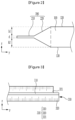
- FIG. 4 is a view for explaining a first usage example in which the multipurpose jig in FIG. 1 is used to set a secondary battery manufacturing apparatus
- FIG. 5 is a view for explaining a second usage example in which the multipurpose jig in FIG. 1 is used to set the secondary battery manufacturing apparatus
- FIGS. 6A and 6B are views for explaining a third usage example in which the multipurpose jig in FIG. 1 is used to set the secondary battery manufacturing apparatus
- FIG. 7 is a view for explaining a fourth usage example in which the multipurpose jig in FIG. 1 is used to set the secondary battery manufacturing apparatus.
- the multipurpose jig 10 may be used to set a center of an electrode tab cutter 30. That is, the electrode tab cutter 30 may include an upper blade 31 and a lower blade 32 based on a position at which the electrode tab is positioned. In this case, the positions of the upper blade 31 and the lower blade 32 need to be set to accurate positions based on the electrode tab to accurately perform the cutting process.
- the lower blade 32 is raised to an operating position first, the multipurpose jig 10 is disposed on a working stage 20, and the tab shape part 210 of the first measurement part 200 is inserted into a portion where the lower blade 32 is positioned.
- the electrode tab cutter 30 is set at the accurate position when interference occurs between the lower blade 32 and the tab shape part 210.
- the position of the electrode tab cutter 30 is set by the multipurpose jig 10 to reduce a defect rate in a cutting process, such that the electrode tab cutter 30 may be set again at the accurate position because the shape of the multipurpose jig 10 is constantly maintained even though repeated setting is performed. Therefore, the accurate and quick setting may be performed.
- the multipurpose jig 10 according to the present embodiment may be used to set an upper position and a lower position of another device, e.g., an electrode tab press, which needs to be adjust in an upper height and a lower height with the electrode tab interposed therebetween.
- another device e.g., an electrode tab press
- the multipurpose jig 10 may be used to set an upper position and a lower position of upper guide 41 and lower guide 42 of a tab guide 40 during the welding process.
- the welding process may be performed to connect the plurality of positive electrode tabs or the plurality of negative electrode tabs connected to the plurality of positive electrodes or the plurality of negative electrodes included in the electrode assembly of the pouch-type secondary battery.
- the tab guide 40 may be applied to collect and fix the plurality of electrode tabs.
- the electrode tabs fixed by the tab guide 40 may be welded by a welding apparatus 50.
- the welding apparatus 50 may include a welding table (or an anvil) 51 and a welder (or a horn) 52.
- the tab guide 40 includes the upper guide 41 and the lower guide 42, and the electrode tabs are set to be disposed between the upper lower guide 41 and lower guide 42.
- the multipurpose jig 10 is disposed on the working stage 20, and the tab shape part 210 of the first measurement part 200 is positioned between the upper guide 41 and the lower guide 42.
- the setting is performed at a position at which the upper guide 41 and the lower guide 42 are in contact with the tab shape part 210. It is preferred that a gap between the upper guide 41 and the lower guide 42 of the tab shape part 210 is at least 0.5 mm or less.
- the multipurpose jig may be used to directly set the position of the welding apparatus 50 or set and inspect a position of another apparatus including an upper device and a lower device with the electrode tab interposed therebetween.
- the multipurpose jig 10 may be used to set the respective upper position and lower position of the upper device and the lower device used for the welding process, which makes it possible to minimize the occurrence of a welding defect or a defect such as disconnection of the electrode tab, enable quick and accurate apparatus setting, and improve efficiency of a manufacturing process.
- the multipurpose jig 10 may be used to set relative position alignment of the upper guide 41 and the lower guide 42 of the tab guide 40 during the welding process.
- the first measurement part 200 is used to set the heights of the upper guide 41 and the lower guide 42 based on the tab shape part 210.
- the second measurement part 300 is used to set the positions of the upper guide 41 and the lower guide 42 based on the y-axis direction.
- the multipurpose jig 10 is inverted, and the end of the protruding portion 310 is disposed to be in contact with the lower guide 42. Thereafter, the graduation part 320 is identified, and the lower guide 42 is disposed so that an interval, which is equal to the predetermined interval in the upper guide 41, is provided between the end of the working stage 20 and the lower guide 42.
- the graduation part 320 is identified in a state in which only the upper guide 41 and the lower guide 42 and the protruding portion 310 are in contact with one another, it is possible to prevent interference that may occur at a portion except for the portion being in contact with the protruding portion 310 even though the multipurpose jig 10 has a sufficient thickness so that the multipurpose jig 10 has the same thickness as the secondary battery as a whole. Therefore, an interval in an assuredly close contact state may be measured by the graduation part 320.
- the upper guide 41 and the lower guide 42 may be aligned at the same position without an error. Therefore, the tab guide 40 may be accurately disposed at a predetermined position based on the longitudinal direction of the secondary battery, i.e., the y-axis direction, which makes it possible to accurately support the electrode tab during the welding process. In addition, the upper guide 41 and the lower guide 42 are aligned at the same position without an error, which makes it possible to prevent a welding error or the like caused by a defect in supporting the electrode tab during the welding process.
- the tab guide 40 may be applied to set various devices that need to be aligned in the longitudinal direction of the secondary battery.
- the auxiliary graduation part 321, which is provided inside the stepped portion, together with the graduation part 320 may be used to perform the setting at various positions and postures.
- an interval between an electrode assembly 60 and the tab guide 40 may be set in the state in which the electrode assembly 60 of the secondary battery is disposed by using the multipurpose jig 10 during the welding process.
- the second measurement part 300 of the multipurpose jig 10, i.e., the protruding portion 310 is disposed on an upper portion of the electrode assembly 60 so as to be directed toward the upper guide 41 in the state in which the electrode assembly 60 is disposed on the working stage 20 so that an electrode tab 61 of the electrode assembly 60 is interposed between the upper guide 41 and the lower guide 42. Further, whether an interval (e) between the end of the separator of the electrode assembly 60 and the upper guide 41 is a predetermined interval or smaller, e.g., 1 mm or less is identified by means of the graduation part 320, and the position of the electrode assembly 60 may be adjusted to satisfy the condition.
- the position of the electrode assembly 60 may be more precisely set by means of the graduation part 320, which makes it possible to accurately set the position of the apparatus to the same position even though the process is performed multiple times.
- the single multipurpose jig according to the embodiment of the present invention may be used to easily and quickly set multiple parts that need to be set in the secondary battery manufacturing apparatus.
- the same position may be set under the same condition even though the setting is performed repeatedly multiple times, which makes it possible to manufacture the secondary battery without causing an error between the manufactured secondary batteries.
Landscapes
- Engineering & Computer Science (AREA)
- Chemical & Material Sciences (AREA)
- Chemical Kinetics & Catalysis (AREA)
- Electrochemistry (AREA)
- General Chemical & Material Sciences (AREA)
- Physics & Mathematics (AREA)
- Optics & Photonics (AREA)
- Mechanical Engineering (AREA)
- Manufacturing & Machinery (AREA)
- Secondary Cells (AREA)
- Connection Of Batteries Or Terminals (AREA)
- Battery Electrode And Active Subsutance (AREA)
Applications Claiming Priority (2)
| Application Number | Priority Date | Filing Date | Title |
|---|---|---|---|
| KR1020210182734A KR20230093815A (ko) | 2021-12-20 | 2021-12-20 | 이차 전지 제조를 위한 다목적 지그 및 이를 이용한 제조 장치의 셋팅 방법 |
| PCT/KR2022/016494 WO2023120938A1 (fr) | 2021-12-20 | 2022-10-26 | Gabarit polyvalent pour la fabrication d'une batterie rechargeable et procédé de réglage d'un appareil de fabrication l'utilisant |
Publications (1)
| Publication Number | Publication Date |
|---|---|
| EP4383443A1 true EP4383443A1 (fr) | 2024-06-12 |
Family
ID=86902860
Family Applications (1)
| Application Number | Title | Priority Date | Filing Date |
|---|---|---|---|
| EP22911576.1A Pending EP4383443A1 (fr) | 2021-12-20 | 2022-10-26 | Gabarit polyvalent pour la fabrication d'une batterie rechargeable et procédé de réglage d'un appareil de fabrication l'utilisant |
Country Status (4)
| Country | Link |
|---|---|
| EP (1) | EP4383443A1 (fr) |
| KR (1) | KR20230093815A (fr) |
| CN (1) | CN117981163A (fr) |
| WO (1) | WO2023120938A1 (fr) |
Family Cites Families (5)
| Publication number | Priority date | Publication date | Assignee | Title |
|---|---|---|---|---|
| KR200443112Y1 (ko) * | 2007-04-12 | 2009-01-20 | 이종성 | 부스바 위치조절수단이 구비된 부스바 가공장치 |
| KR101085015B1 (ko) * | 2009-02-18 | 2011-11-18 | 주식회사 우진정공 | 부스바의 펀칭위치 설정구조가 구비된 부스바 가공장치 |
| JP6624678B2 (ja) * | 2016-03-29 | 2019-12-25 | 東レエンジニアリング株式会社 | 電池用極板の製造装置 |
| JP2020092016A (ja) * | 2018-12-06 | 2020-06-11 | 株式会社豊田自動織機 | 蓄電装置の製造装置 |
| KR20210017804A (ko) * | 2019-08-09 | 2021-02-17 | 상신이디피(주) | 프레스 장치 |
-
2021
- 2021-12-20 KR KR1020210182734A patent/KR20230093815A/ko unknown
-
2022
- 2022-10-26 CN CN202280061035.9A patent/CN117981163A/zh active Pending
- 2022-10-26 EP EP22911576.1A patent/EP4383443A1/fr active Pending
- 2022-10-26 WO PCT/KR2022/016494 patent/WO2023120938A1/fr active Application Filing
Also Published As
| Publication number | Publication date |
|---|---|
| KR20230093815A (ko) | 2023-06-27 |
| CN117981163A (zh) | 2024-05-03 |
| WO2023120938A1 (fr) | 2023-06-29 |
Similar Documents
| Publication | Publication Date | Title |
|---|---|---|
| KR20170130091A (ko) | 리드 용접 장치, 이러한 리드 용접 장치를 통해 제조되는 배터리 모듈 및 이러한 배터리 모듈을 포함하는 배터리 팩 | |
| KR20160126891A (ko) | 전지셀들을 포함하고 있는 전지셀 어셈블리의 전극단자 용접 장치 및 이를 사용한 용접 방법 | |
| US20180287111A1 (en) | Method for assembling battery pack, and battery pack | |
| CN110199408B (zh) | 电池组和包括该电池组的车辆 | |
| US20170365838A1 (en) | Battery system | |
| EP3840098A1 (fr) | Ensemble d'électrodes et procédé d'inspection associé | |
| EP3958655A1 (fr) | Dispositif de pliage de carte de circuit imprimé souple de cellule de batterie et procédé de pliage l'utilisant | |
| EP4098393A1 (fr) | Appareil de pliage et de soudage de fil d'électrode et procédé de soudage de fil d'électrode le mettant en ?uvre | |
| US20120240654A1 (en) | Current collector shape adjusting device | |
| WO2022154008A1 (fr) | Dispositif de détection de tension et module de batterie | |
| CN111741837A (zh) | 用于电池单体的电极引线切割设备 | |
| EP4383443A1 (fr) | Gabarit polyvalent pour la fabrication d'une batterie rechargeable et procédé de réglage d'un appareil de fabrication l'utilisant | |
| JP7151123B2 (ja) | 蓄電素子の検査方法及び蓄電素子 | |
| CN113875085B (zh) | 具有改进的可焊接性的电池单元及电池单元处理设备 | |
| KR101678810B1 (ko) | 용접봉 정렬용 홀을 포함하고 있는 지그를 구비한 용접 장치 | |
| KR20230097685A (ko) | 이차 전지 제조를 위한 다목적 지그 및 이를 이용하는 측정 방법 | |
| US20220190449A1 (en) | Metal plate for resistance welding and resistance welding method using the same | |
| EP4391207A1 (fr) | Gabarit polyvalent pour la fabrication d'une batterie rechargeable et procédé de réglage de l'appareil de fabrication correspondant | |
| KR102359235B1 (ko) | 버스바 조립용 리드 자동 성형장치 및 그것을 이용한 리드 자동 성형방법 | |
| CN221292354U (zh) | 熔接设备的底座结构 | |
| EP4249904A1 (fr) | Dispositif et procédé de détection de défaut interne d'élément de batterie à l'aide de tdr | |
| WO2022154007A1 (fr) | Module de batterie et procédé de fabrication de module de batterie | |
| US20230198060A1 (en) | Base material assembly for mechanical and electrical connection, and riveting method therefor | |
| KR20230083478A (ko) | 용접 검사용 스틱 | |
| KR20240087135A (ko) | 스택 셀의 전압 극성 검사지그 |
Legal Events
| Date | Code | Title | Description |
|---|---|---|---|
| STAA | Information on the status of an ep patent application or granted ep patent |
Free format text: STATUS: THE INTERNATIONAL PUBLICATION HAS BEEN MADE |
|
| PUAI | Public reference made under article 153(3) epc to a published international application that has entered the european phase |
Free format text: ORIGINAL CODE: 0009012 |
|
| STAA | Information on the status of an ep patent application or granted ep patent |
Free format text: STATUS: REQUEST FOR EXAMINATION WAS MADE |
|
| 17P | Request for examination filed |
Effective date: 20240304 |
|
| AK | Designated contracting states |
Kind code of ref document: A1 Designated state(s): AL AT BE BG CH CY CZ DE DK EE ES FI FR GB GR HR HU IE IS IT LI LT LU LV MC ME MK MT NL NO PL PT RO RS SE SI SK SM TR |