EP4382352A1 - Vehicle - Google Patents
Vehicle Download PDFInfo
- Publication number
- EP4382352A1 EP4382352A1 EP23203661.6A EP23203661A EP4382352A1 EP 4382352 A1 EP4382352 A1 EP 4382352A1 EP 23203661 A EP23203661 A EP 23203661A EP 4382352 A1 EP4382352 A1 EP 4382352A1
- Authority
- EP
- European Patent Office
- Prior art keywords
- battery
- vehicle
- unit
- cleansing
- fastening member
- Prior art date
- Legal status (The legal status is an assumption and is not a legal conclusion. Google has not performed a legal analysis and makes no representation as to the accuracy of the status listed.)
- Pending
Links
Images


Classifications
-
- B—PERFORMING OPERATIONS; TRANSPORTING
- B60—VEHICLES IN GENERAL
- B60K—ARRANGEMENT OR MOUNTING OF PROPULSION UNITS OR OF TRANSMISSIONS IN VEHICLES; ARRANGEMENT OR MOUNTING OF PLURAL DIVERSE PRIME-MOVERS IN VEHICLES; AUXILIARY DRIVES FOR VEHICLES; INSTRUMENTATION OR DASHBOARDS FOR VEHICLES; ARRANGEMENTS IN CONNECTION WITH COOLING, AIR INTAKE, GAS EXHAUST OR FUEL SUPPLY OF PROPULSION UNITS IN VEHICLES
- B60K1/00—Arrangement or mounting of electrical propulsion units
- B60K1/04—Arrangement or mounting of electrical propulsion units of the electric storage means for propulsion
-
- B—PERFORMING OPERATIONS; TRANSPORTING
- B60—VEHICLES IN GENERAL
- B60S—SERVICING, CLEANING, REPAIRING, SUPPORTING, LIFTING, OR MANOEUVRING OF VEHICLES, NOT OTHERWISE PROVIDED FOR
- B60S1/00—Cleaning of vehicles
- B60S1/02—Cleaning windscreens, windows or optical devices
- B60S1/56—Cleaning windscreens, windows or optical devices specially adapted for cleaning other parts or devices than front windows or windscreens
-
- B—PERFORMING OPERATIONS; TRANSPORTING
- B60—VEHICLES IN GENERAL
- B60S—SERVICING, CLEANING, REPAIRING, SUPPORTING, LIFTING, OR MANOEUVRING OF VEHICLES, NOT OTHERWISE PROVIDED FOR
- B60S1/00—Cleaning of vehicles
- B60S1/62—Other vehicle fittings for cleaning
- B60S1/66—Other vehicle fittings for cleaning for cleaning vehicle exterior
-
- B—PERFORMING OPERATIONS; TRANSPORTING
- B08—CLEANING
- B08B—CLEANING IN GENERAL; PREVENTION OF FOULING IN GENERAL
- B08B1/00—Cleaning by methods involving the use of tools
- B08B1/10—Cleaning by methods involving the use of tools characterised by the type of cleaning tool
- B08B1/12—Brushes
-
- B—PERFORMING OPERATIONS; TRANSPORTING
- B60—VEHICLES IN GENERAL
- B60L—PROPULSION OF ELECTRICALLY-PROPELLED VEHICLES; SUPPLYING ELECTRIC POWER FOR AUXILIARY EQUIPMENT OF ELECTRICALLY-PROPELLED VEHICLES; ELECTRODYNAMIC BRAKE SYSTEMS FOR VEHICLES IN GENERAL; MAGNETIC SUSPENSION OR LEVITATION FOR VEHICLES; MONITORING OPERATING VARIABLES OF ELECTRICALLY-PROPELLED VEHICLES; ELECTRIC SAFETY DEVICES FOR ELECTRICALLY-PROPELLED VEHICLES
- B60L53/00—Methods of charging batteries, specially adapted for electric vehicles; Charging stations or on-board charging equipment therefor; Exchange of energy storage elements in electric vehicles
- B60L53/60—Monitoring or controlling charging stations
- B60L53/66—Data transfer between charging stations and vehicles
-
- B—PERFORMING OPERATIONS; TRANSPORTING
- B60—VEHICLES IN GENERAL
- B60S—SERVICING, CLEANING, REPAIRING, SUPPORTING, LIFTING, OR MANOEUVRING OF VEHICLES, NOT OTHERWISE PROVIDED FOR
- B60S1/00—Cleaning of vehicles
- B60S1/02—Cleaning windscreens, windows or optical devices
- B60S1/46—Cleaning windscreens, windows or optical devices using liquid; Windscreen washers
- B60S1/48—Liquid supply therefor
-
- B—PERFORMING OPERATIONS; TRANSPORTING
- B60—VEHICLES IN GENERAL
- B60S—SERVICING, CLEANING, REPAIRING, SUPPORTING, LIFTING, OR MANOEUVRING OF VEHICLES, NOT OTHERWISE PROVIDED FOR
- B60S1/00—Cleaning of vehicles
- B60S1/02—Cleaning windscreens, windows or optical devices
- B60S1/54—Cleaning windscreens, windows or optical devices using gas, e.g. hot air
-
- H—ELECTRICITY
- H01—ELECTRIC ELEMENTS
- H01M—PROCESSES OR MEANS, e.g. BATTERIES, FOR THE DIRECT CONVERSION OF CHEMICAL ENERGY INTO ELECTRICAL ENERGY
- H01M50/00—Constructional details or processes of manufacture of the non-active parts of electrochemical cells other than fuel cells, e.g. hybrid cells
- H01M50/20—Mountings; Secondary casings or frames; Racks, modules or packs; Suspension devices; Shock absorbers; Transport or carrying devices; Holders
- H01M50/262—Mountings; Secondary casings or frames; Racks, modules or packs; Suspension devices; Shock absorbers; Transport or carrying devices; Holders with fastening means, e.g. locks
-
- B—PERFORMING OPERATIONS; TRANSPORTING
- B08—CLEANING
- B08B—CLEANING IN GENERAL; PREVENTION OF FOULING IN GENERAL
- B08B5/00—Cleaning by methods involving the use of air flow or gas flow
- B08B5/02—Cleaning by the force of jets, e.g. blowing-out cavities
-
- B—PERFORMING OPERATIONS; TRANSPORTING
- B60—VEHICLES IN GENERAL
- B60K—ARRANGEMENT OR MOUNTING OF PROPULSION UNITS OR OF TRANSMISSIONS IN VEHICLES; ARRANGEMENT OR MOUNTING OF PLURAL DIVERSE PRIME-MOVERS IN VEHICLES; AUXILIARY DRIVES FOR VEHICLES; INSTRUMENTATION OR DASHBOARDS FOR VEHICLES; ARRANGEMENTS IN CONNECTION WITH COOLING, AIR INTAKE, GAS EXHAUST OR FUEL SUPPLY OF PROPULSION UNITS IN VEHICLES
- B60K1/00—Arrangement or mounting of electrical propulsion units
- B60K1/04—Arrangement or mounting of electrical propulsion units of the electric storage means for propulsion
- B60K2001/0405—Arrangement or mounting of electrical propulsion units of the electric storage means for propulsion characterised by their position
- B60K2001/0438—Arrangement under the floor
-
- B—PERFORMING OPERATIONS; TRANSPORTING
- B60—VEHICLES IN GENERAL
- B60K—ARRANGEMENT OR MOUNTING OF PROPULSION UNITS OR OF TRANSMISSIONS IN VEHICLES; ARRANGEMENT OR MOUNTING OF PLURAL DIVERSE PRIME-MOVERS IN VEHICLES; AUXILIARY DRIVES FOR VEHICLES; INSTRUMENTATION OR DASHBOARDS FOR VEHICLES; ARRANGEMENTS IN CONNECTION WITH COOLING, AIR INTAKE, GAS EXHAUST OR FUEL SUPPLY OF PROPULSION UNITS IN VEHICLES
- B60K1/00—Arrangement or mounting of electrical propulsion units
- B60K1/04—Arrangement or mounting of electrical propulsion units of the electric storage means for propulsion
- B60K2001/0455—Removal or replacement of the energy storages
-
- B—PERFORMING OPERATIONS; TRANSPORTING
- B60—VEHICLES IN GENERAL
- B60K—ARRANGEMENT OR MOUNTING OF PROPULSION UNITS OR OF TRANSMISSIONS IN VEHICLES; ARRANGEMENT OR MOUNTING OF PLURAL DIVERSE PRIME-MOVERS IN VEHICLES; AUXILIARY DRIVES FOR VEHICLES; INSTRUMENTATION OR DASHBOARDS FOR VEHICLES; ARRANGEMENTS IN CONNECTION WITH COOLING, AIR INTAKE, GAS EXHAUST OR FUEL SUPPLY OF PROPULSION UNITS IN VEHICLES
- B60K1/00—Arrangement or mounting of electrical propulsion units
- B60K1/04—Arrangement or mounting of electrical propulsion units of the electric storage means for propulsion
- B60K2001/0455—Removal or replacement of the energy storages
- B60K2001/0472—Removal or replacement of the energy storages from below
-
- B—PERFORMING OPERATIONS; TRANSPORTING
- B60—VEHICLES IN GENERAL
- B60K—ARRANGEMENT OR MOUNTING OF PROPULSION UNITS OR OF TRANSMISSIONS IN VEHICLES; ARRANGEMENT OR MOUNTING OF PLURAL DIVERSE PRIME-MOVERS IN VEHICLES; AUXILIARY DRIVES FOR VEHICLES; INSTRUMENTATION OR DASHBOARDS FOR VEHICLES; ARRANGEMENTS IN CONNECTION WITH COOLING, AIR INTAKE, GAS EXHAUST OR FUEL SUPPLY OF PROPULSION UNITS IN VEHICLES
- B60K1/00—Arrangement or mounting of electrical propulsion units
- B60K1/04—Arrangement or mounting of electrical propulsion units of the electric storage means for propulsion
- B60K2001/0455—Removal or replacement of the energy storages
- B60K2001/0494—Removal or replacement of the energy storages with arrangements for sliding
-
- B—PERFORMING OPERATIONS; TRANSPORTING
- B60—VEHICLES IN GENERAL
- B60L—PROPULSION OF ELECTRICALLY-PROPELLED VEHICLES; SUPPLYING ELECTRIC POWER FOR AUXILIARY EQUIPMENT OF ELECTRICALLY-PROPELLED VEHICLES; ELECTRODYNAMIC BRAKE SYSTEMS FOR VEHICLES IN GENERAL; MAGNETIC SUSPENSION OR LEVITATION FOR VEHICLES; MONITORING OPERATING VARIABLES OF ELECTRICALLY-PROPELLED VEHICLES; ELECTRIC SAFETY DEVICES FOR ELECTRICALLY-PROPELLED VEHICLES
- B60L50/00—Electric propulsion with power supplied within the vehicle
- B60L50/50—Electric propulsion with power supplied within the vehicle using propulsion power supplied by batteries or fuel cells
- B60L50/60—Electric propulsion with power supplied within the vehicle using propulsion power supplied by batteries or fuel cells using power supplied by batteries
- B60L50/66—Arrangements of batteries
-
- B—PERFORMING OPERATIONS; TRANSPORTING
- B60—VEHICLES IN GENERAL
- B60L—PROPULSION OF ELECTRICALLY-PROPELLED VEHICLES; SUPPLYING ELECTRIC POWER FOR AUXILIARY EQUIPMENT OF ELECTRICALLY-PROPELLED VEHICLES; ELECTRODYNAMIC BRAKE SYSTEMS FOR VEHICLES IN GENERAL; MAGNETIC SUSPENSION OR LEVITATION FOR VEHICLES; MONITORING OPERATING VARIABLES OF ELECTRICALLY-PROPELLED VEHICLES; ELECTRIC SAFETY DEVICES FOR ELECTRICALLY-PROPELLED VEHICLES
- B60L53/00—Methods of charging batteries, specially adapted for electric vehicles; Charging stations or on-board charging equipment therefor; Exchange of energy storage elements in electric vehicles
- B60L53/80—Exchanging energy storage elements, e.g. removable batteries
-
- Y—GENERAL TAGGING OF NEW TECHNOLOGICAL DEVELOPMENTS; GENERAL TAGGING OF CROSS-SECTIONAL TECHNOLOGIES SPANNING OVER SEVERAL SECTIONS OF THE IPC; TECHNICAL SUBJECTS COVERED BY FORMER USPC CROSS-REFERENCE ART COLLECTIONS [XRACs] AND DIGESTS
- Y02—TECHNOLOGIES OR APPLICATIONS FOR MITIGATION OR ADAPTATION AGAINST CLIMATE CHANGE
- Y02T—CLIMATE CHANGE MITIGATION TECHNOLOGIES RELATED TO TRANSPORTATION
- Y02T10/00—Road transport of goods or passengers
- Y02T10/60—Other road transportation technologies with climate change mitigation effect
- Y02T10/7072—Electromobility specific charging systems or methods for batteries, ultracapacitors, supercapacitors or double-layer capacitors
Definitions
- the present disclosure relates to a vehicle.
- CN 106627235 A discloses fastening a battery to a vehicle body by inserting bolts into insertion holes.
- An object of the present disclosure is to provide a vehicle in which a tool can be fit to a fastening member.
- a vehicle according to one aspect of the present disclosure includes a vehicle body including a mounting portion that is configured to mount a battery, the battery disposed in the mounting portion, a fastening member for fastening the battery to the mounting portion, and a cleansing unit for cleansing the fastening member.
- a vehicle in which a tool can be fit to a fastening member can be provided.
- FIG. 1 is a diagram illustrating a battery replacing device 100 and an electrified vehicle 200 according to the present embodiment.
- the battery replacing device 100 is a device for replacing a battery (used battery) 201 attached to the electrified vehicle 200 with a battery (new battery) 101 that is charged.
- the battery 201 and the battery 101 are examples of a "first battery” and a "second battery” of the present disclosure, respectively.
- the electrified vehicle 200 has a vehicle body 200a and a cleansing unit 200d.
- the vehicle body 200a has a mounting portion 200c in which the batteries 101, 201 can be mounted. As illustrated in FIG. 3 , the mounting portion 200c has a shape that is recessed upward from a lower face 200b of the vehicle body 200a.
- the batteries 101 and 201 are fastened to the mounting portion 200c by fastening members 205 (see FIGS. 7 and 8 ) such as bolts or the like.
- the cleansing unit 200d cleanses the fastening members 205. As illustrated in FIGS. 8 and 9 , the cleansing unit 200d has a spray unit 200e, a supply unit 200f, and a cover 200h.
- the spray unit 200e sprays a cleansing fluid (air, cleansing liquid, or the like) F that is capable of cleansing the fastening member 205, toward the fastening member 205.
- the spray unit 200e is movable in an up-down direction between a spraying position (position illustrated in FIG. 9 ) and a stored position (position illustrated in FIG. 8 ).
- the spraying position is a position where the cleansing fluid F can be sprayed toward the fastening member 205 from below.
- the stored position is a position where the spray unit 200e is stowed inside the vehicle body 200a.
- the lower face 200b of the vehicle body 200a is provided with an opening 200b1 that enables the spray unit 200e to pass therethrough.
- the supply unit 200f supplies the cleansing fluid to the spray unit 200e.
- the supply unit 200f includes a pump 200g that feeds the cleansing fluid towards the spray unit 200e.
- the spray unit 200e moves from the stored position to the spraying position, under pressure of the cleansing fluid that is generated by driving the pump 200g. Note that when the pump 200g is stopped, the spray unit 200e returns from the spraying position to the stored position under a biasing force of a biasing member (omitted from illustration) that is provided in the supply unit 200f.
- the cover 200h has a shape that closes the opening 200b1 formed in the lower face 200b of the vehicle body 200a.
- the cover 200h is fixed to a lower face of the spray unit 200e.
- the cover 200h closes the opening 200b1 when the spray unit 200e is located at the stored position.
- the battery replacing device 100 includes a battery replacing station 100a, a storage compartment 100b, and an underfloor area 100c.
- the battery replacing station 100a is a station where removal of the battery 201 from the electrified vehicle 200 and attachment of the battery 101 to the electrified vehicle 200 are performed.
- the battery replacing station 100a is provided with an entrance 102 from which the electrified vehicle 200 enters and exits.
- the storage compartment 100b stores batteries 101 that are charged.
- the storage compartment 100b is built annexed to the battery replacing station 100a.
- a charging facility 51 capable of charging the battery 201 removed from the electrified vehicle 200 is provided in the storage compartment 100b.
- the battery 201 is charged by the charging facility 51 in the storage compartment 100b.
- the battery 101 charged in the storage compartment 100b, i.e., the battery 101 that is charged is transported to the electrified vehicle 200 after being moved to a temporary storage site 40 provided in the underfloor area 100c.
- the underfloor area 100c is provided below the battery replacing station 100a and the storage compartment 100b.
- the underfloor area 100c is provided with a battery placement table 34, a lift unit 35, a first transporting unit 36, and a second transporting unit 37, which will be described later.
- the battery replacing device 100 includes a control device 10 and a drive device 30.
- the control device 10 includes a processor 11, memory 12, and a communication unit 13.
- the memory 12 stores programs to be executed by the processor 11, as well as information used by the programs (e.g., maps, mathematical expressions, and various types of parameters).
- the processor 11 controls the drive device 30, which will be described in detail later.
- the communication unit 13 includes various types of communication interfaces.
- the processor 11 controls the communication unit 13.
- the communication unit 13 communicates with a data communication module (DCM) and so forth of the electrified vehicle 200. Bi-directional communication can be performed between the communication unit 13 and the electrified vehicle 200. Note that the communication unit 13 may communicate with a mobile terminal or the like owned by a user of the electrified vehicle 200.
- DCM data communication module
- the battery replacing device 100 is provided with a vehicle stop area 103.
- the communication unit 13 receives an instruction signal to start the battery replacement work from the electrified vehicle 200.
- the processor 11 starts controlling the battery replacement work based on reception of the instruction signal by the communication unit 13. Note that the electrified vehicle 200 stops in the vehicle stop area 103 such that a front-rear direction matches an X direction and a right-left direction matches a Y direction.
- the drive device 30 includes wheel securing units 31 (see FIG. 2 ), a shutter 32 (see FIG. 2 ), the battery placement table 34 (see FIG. 1 ), the lift unit 35 (see FIG. 1 ), the first transporting unit 36 (See FIG. 1 ), and the second transporting unit 37 (See FIG. 1 ).
- the wheel securing units 31 are provided so as to correspond to each of four wheels 202 of electrified vehicle 200.
- Each of the wheel securing units 31 includes a pressing member 31a and a lateral roller portion 31b.
- the pressing members 31a move the wheels 202 by pressing the wheels 202 from the outer side thereof (sideward).
- the pressing members 31a are disposed straddling the lateral roller portions 31b.
- the wheels 202 are positioned by the wheel securing units 31.
- the lateral roller portions 31b are made up of a plurality of rollers of which the rotation axes extend in the X direction.
- the rollers of the lateral roller portions 31b are arrayed in the Y direction. Rotating the rollers of the lateral roller portions 31b moves the pressing members 31a in the Y direction.
- the shutter 32 is provided in the vehicle stop area 103.
- the shutter 32 is configured to be capable of opening and closing an opening portion 32a formed in a floor surface FL of the vehicle stop area 103.
- the shutter 32 can be switched between an open state in which the opening portion 32a is open and a closed state in which the opening portion 32a is closed.
- the lift unit 35 can move in the up-down direction through the opening portion 32a, between a position higher than the floor surface FL and a position lower than the floor surface FL. As illustrated in FIG. 3 , the lift unit 35 can rise to a position where the wheels 202 of the electrified vehicle 200 are lifted off of the floor surface FL, in a state of holding the electrified vehicle 200 from below. The lift unit 35 raises the electrified vehicle so that a height H of the lower face 200b of the vehicle body 200a from the floor surface FL reaches a predetermined height.
- the lift unit 35 includes a pair of lifting bars 35a that are disposed spaced apart in a direction (Y direction) orthogonal to the up-down direction. Each of the lifting bars 35a is provided with two projecting portions 35b projecting upward. The electrified vehicle 200 is supported from below by two projecting portions 35b of each of the lifting bars 35a, (i.e., four projecting portions 35b).
- the battery placement table 34 is disposed below the battery replacing station 100a, more specifically below the opening portion 32a.
- the battery placement table 34 is capable of having the batteries 101 and 201 placed thereon and is movable in the up-down direction. As illustrated in FIG. 4 , the battery placement table 34 has a base portion 34e, two positioning pins 34a, four locking/unlocking tools 34b, roller portions 34c, and a stopper 34f.
- the base portion 34e is disposed between the lifting bars 35a.
- the base portion 34e is movable in the up-down direction.
- the base portion 34e is formed having a form of a flat plate.
- the base portion 34e has an outer shape that is larger than the outer shape of the batteries 101 and 201.
- the base portion 34e is configured to be movable in a lateral direction below the electrified vehicle 200. Specifically, the base portion 34e is movable in the X direction (X1 direction, X2 direction) and the Y direction (Y1 direction, Y2 direction).
- the base portion 34e is rotatable so as to change the orientation (angle) thereof in the XY plane. Note that each of the lifting bars 35a may also be movable in the same manner as the base portion 34e.
- Each positioning pin 34a is provided on the base portion 34e. Each positioning pin 34a is a part for performing positioning of the vehicle body 200a of the electrified vehicle 200 and the base portion 34e. One positioning pin 34a is provided at one end portion of the base portion 34e in a direction parallel to a vehicle width direction (Y direction). The other positioning pin 34a is provided at the other end portion of the base portion 34e in the direction parallel to the vehicle width direction (Y direction).
- the lower face 200b of the vehicle body 200a of the electrified vehicle 200 is provided with pin insertion holes 208 into which the positioning pins 34a are inserted.
- Each positioning pin 34a is insertable into a corresponding one of the pin insertion holes 208.
- Each locking/unlocking tool 34b is movable in the up-down direction. Each locking/unlocking tool 34b is movable in the up-down direction with respect to the base portion 34e. As illustrated in FIG. 4 , each locking/unlocking tool 34b is disposed on an inward side of the positioning pins 34a in the Y direction. Each locking/unlocking tool 34b is disposed on an outer side of the base portion 34e in the X direction.
- the battery 201 has a bottom face 201e, and the bottom face 201e is provided with tool insertion holes 201f into which the locking/unlocking tools 34b are inserted.
- Tool insertion holes are also provided on a bottom face of the battery 101. Each locking/unlocking tool 34b can be inserted into a corresponding one of the tool insertion holes.
- the roller portions 34c are provided in the base portion 34e.
- the roller portions 34c are rotatable about rotation axes extending in the X direction. Rotating the roller portions 34c in one direction moves the batteries 101 and 201 relative to the base portion 34e to one side in the Y direction (e.g., to the Y1 side), and rotating the roller portions 34c in the other direction moves the batteries 101 and 201 relative to the base portion 34e to the other side in the Y direction.
- a marker 34d is provided at a distal end portion of each positioning pin 34a.
- the marker 34d is made up of a light emitter such as a light-emitting diode (LED) or the like.
- the marker 34d may have an upwardly tapered form.
- the stopper 34f is provided on the base portion 34e.
- the stopper 34f will be described later.
- the first transporting unit 36 transports the battery 101 stored in the storage compartment 100b toward the battery placement table 34.
- the underfloor area 100c is provided with the temporary storage site 40 for temporarily storing the charged battery 101 that was stored in the storage compartment 100b, and the first transporting unit 36 can transport the battery 101 from the temporary storage site 40 toward the battery placement table 34.
- the first transporting unit 36 may be of a conveyor belt type, for example.
- the second transporting unit 37 transports the used battery 201, which is removed from the electrified vehicle 200 and placed on the battery placement table 34, away from the battery placement table 34.
- a storage space 42 for storing the battery 201 is provided at a position spaced apart from the storage compartment 100b, and the second transporting unit 37 transports the battery 201 from the battery placement table 34 toward the storage space 42, in the transporting direction in which the first transporting unit 36 transports the battery 101 toward the battery placement table 34 (Y2 direction).
- the first transporting unit 36 and the second transporting unit 37 are disposed so as to be arrayed on the same straight line.
- the second transporting unit 37 may also be of a conveyor belt type, for example.
- a charging facility 52 capable of charging the battery 201 is provided in the storage space 42.
- the battery 201 stored in the storage space 42 is transported to the storage compartment 100b by a transport unit (omitted from illustration) after charging by the charging facility 52 is completed, or during charging thereof.
- the transport unit may be made up of the first transporting unit 36 and the second transporting unit 37.
- the stopper 34f is provided at a portion of the base portion 34e that is on a downstream side from the roller portions 34c in the transporting direction (Y2 direction).
- the stopper 34f abuts the battery 101, which is transported from the first transporting unit 36 to the base portion 34e, from a direction opposite to the transporting direction.
- the position of the stopper 34f in a direction parallel to the transporting direction (Y direction) is set in accordance with the position of the battery 201 to be mounted in electrified vehicle 200.
- the stopper 34f is movable in the up-down direction between a projecting position (position illustrated in FIG.
- Movement of the stopper 34f between the projecting position and the sunken position is controlled by the processor 11 of the control device 10.
- the processor 11 positions the stopper 34f at the projecting position when the charged battery 101 moves from the first transporting unit 36 to the base portion 34e, and positions the stopper 34f at the sunken position when the used battery 201 moves from the base portion 34e to the second transporting unit 37.
- the electrified vehicle 200 transmits information about the electrified vehicle 200 and information about the battery 201 to the communication unit 13 of the battery replacing device 100.
- an operation is made at an automotive navigation system (omitted from illustration) of the electrified vehicle 200, to transmit each of the above information, thereby transmitting each of the above information to the communication unit 13.
- the electrified vehicle 200 transmits each piece of the above information before entering the battery replacing device 100. Note that each piece of the above information may be transmitted after the electrified vehicle 200 enters the battery replacing device 100.
- step S1 the communication unit 13 of the battery replacing device 100 acquires, through communication, the information regarding the electrified vehicle 200 and the information regarding the battery 201, transmitted from the electrified vehicle 200 in step S21.
- Each piece of the acquired information is stored in the memory 12 (see FIG. 1 ).
- the communication unit 13 may also acquire information regarding capacity (charge capacity) of the battery 201 and the state of charge (SOC) of the battery 201.
- step S22 the electrified vehicle 200 that is stopped in the vehicle stop area 103 transmits an instruction signal to the communication unit 13, to start battery replacement work.
- step S2 the communication unit 13 receives the instruction signal transmitted from the electrified vehicle 200 in step S22.
- the processor 11 may transmit an instruction message or the like to the user of electrified vehicle 200 through the communication unit 13, for turning ignition power to an off state.
- step S3 the processor 11 adjusts the positions of the wheel securing units 31 (see FIG. 2 ) based on the information (vehicle information and battery information) acquired through the communication unit 13 in step S1. Note that the processor 11 may control each of the four wheel securing units 31 independently of each other.
- the position and the orientation of the vehicle body 200a in the lateral direction are adjusted, and also the position and the orientation of the battery 201 in the lateral direction are adjusted.
- the battery 201 is moved to a predetermined position above the opening portion 32a.
- step S4 the processor 11 places the shutter 32 in an open state and raises the lift unit 35 in the state in which the shutter 32 is open.
- the lift unit 35 lifts the electrified vehicle 200 so that the height H of the lower face 200b of the vehicle body 200a from the floor surface FL reaches the predetermined height (see FIG. 3 ).
- the cleansing unit 200d cleanses the fastening members 205 either by the time step S4 is completed, or before step S5 is started.
- the pump 200g of the supply unit 200f is driven.
- the spray unit 200e moves from the stored position to the spraying position under the pressure of the cleansing fluid F generated thereby, and sprays the cleansing fluid F toward the fastening members 205.
- the fastening members 205 are cleansed, so that the foreign matter adhering to the fastening members 205 or the vicinity thereof (tool insertion holes 201f and so forth) is removed.
- cleansing of the fastening members 205 may be performed inside the battery replacing station 100a or may be performed outside of the battery replacing station 100a.
- step S5 the used battery 201 is removed from the vehicle body 200a of the electrified vehicle 200.
- the processor 11 raises the battery placement table 34.
- the positioning pins 34a are inserted into the pin insertion holes 208 formed in the lower face 200b of the vehicle body 200a, and also the locking/unlocking tools 34b are inserted into the tool insertion holes 201f formed in the bottom face 201e of the battery 201, and the base portion 34e either abuts or approaches the bottom face 201e of the battery 201.
- the battery placement table 34 is positioned with respect to the electrified vehicle 200 (i.e., as to the battery 201). Note that at this time, the positioning pins 34a are inserted into the pin insertion holes 208 prior to the locking/unlocking tools 34b being inserted into the tool insertion holes 201f.
- the processor 11 raises the locking/unlocking tools 34b in a state in which the locking/unlocking tools 34b are inserted into the tool insertion holes 201f.
- the processor 11 then drives (rotates) the locking/unlocking tools 34b inserted into the tool insertion holes 201f. This unlocks the fastening members 205 in the tool insertion holes 201f.
- the battery 201 is removed from the vehicle body 200a, and placed on the base portion 34e. Note that the timing at which the positioning pins 34a are inserted into the pin insertion holes 208 and the timing at which the locking/unlocking tools 34b are inserted into the tool insertion holes 201f may be the same as each other.
- step S6 the battery 201 removed from the vehicle body 200a in step S5 is transported to the storage space 42 (see FIG. 1 ).
- the processor 11 lowers the battery placement table 34, on which the battery 201 is placed, to the height position of the second transporting unit 37 (see FIG. 1 ).
- the processor 11 lowers the lift unit 35 to a position below the battery placement table 34 (e.g., the position illustrated in FIG. 1 ).
- the vehicle body 200a is no longer held by the lift unit 35, and consequently the electrified vehicle 200 is placed on the floor surface FL of the vehicle stop area 103.
- the processor 11 positions the stopper 34f at the sunken position.
- the processor 11 drives the roller portions 34c (see FIG.
- the battery 201 moves over the base portion 34e, in the transporting direction (Y2 direction).
- the battery 201 placed on the base portion 34e moves over the base portion 34e toward the second transporting unit 37 without abutting the stopper 34f, and is relocated from the base portion 34e to the second transporting unit 37.
- the battery 201 is transported to the storage space 42 by the second transporting unit 37 and stored therein. This battery 201 may be charged at the charging facility 52 in the storage space 42. Note that the battery 201 is transported to the storage compartment 100b by the transporting unit, either after charging is completed or during charging.
- step S7 the processor 11 transports the charged battery 101 stored in the storage compartment 100b to the battery placement table 34. Specifically, after transporting the battery 101 from the storage compartment 100b to the temporary storage site 40 in the underfloor area 100c, the processor 11 transports the battery 101 in a transporting direction from the temporary storage site 40 to the battery placement table 34 (Y2 direction) by the first transporting unit 36. At this time, the processor 11 positions the stopper 34f at the projecting position. Upon the battery 101 being relocated from the first transporting unit 36 to the base portion 34e, the processor 11 drives the roller portions 34c so that the battery 101 moves over the base portion 34e in the transporting direction. As a result, the battery 101 abuts the stopper 34f and thus stops at the predetermined position on the base portion 34e.
- step S8 the processor 11 performs control to attach the battery 101 that is charged to the vehicle body 200a. Specifically, the processor 11 raises the lift unit 35 so that the height H of the lower face 200b of the vehicle body 200a from the floor surface FL of the vehicle stop area 103 reaches the predetermined height.
- the processor 11 raises the battery placement table 34. Accordingly, the positioning pins 34a are inserted into the pin insertion holes.
- the processor 11 raises the locking/unlocking tools 34b in this state.
- the locking/unlocking tools 34b are inserted into the tool insertion holes of the battery 101.
- the processor 11 then drives (rotates) the locking/unlocking tools 34b. Accordingly, the bolts inside the tool insertion holes are locked.
- the vehicle-side connector (omitted from illustration) and the connector (omitted from illustration) of the battery 101 are locked. As a result, attachment of the battery 101 that is charged, to the vehicle body 200a, is completed.
- step S9 the processor 11 lowers the battery placement table 34 and the lift unit 35, and performs retraction thereof from the electrified vehicle 200. Thereafter, the processor 11 places the shutter 32 in a closed state (see FIG. 2 ).
- step S10 the processor 11 notifies the electrified vehicle 200 through the communication unit 13 that the battery replacement work has been completed.
- step S23 the electrified vehicle 200 receives the notification transmitted from the communication unit 13 of the battery replacing device 100 in step S10.
- the electrified vehicle 200 is brought into a state in which the ignition power can be turned on. Thereafter, the processing ends.
- the present disclosure is not limited to this.
- the position of the drive device 30 may be adjusted based on information regarding either one of the electrified vehicle 200 and the battery 201.
- the electrified vehicle 200 includes the cleansing unit 200d for cleansing the fastening members 205, and accordingly the locking/unlocking tools 34b for removing the fastening members 205 can effectively fit the fastening members 205.
- the cleansing unit 200d may be provided in the battery replacing station 100a.
- the cleansing unit 200d is provided on the floor surface FL of the vehicle stop area 103, the battery placement table 34, or the like.
- the cleansing unit 200d may have a slider 200j and a cam lever 200m, as illustrated in FIGS. 10 and 11 .
- the slider 200j is provided on the vehicle body 200a.
- the slider 200j is movable with respect to the vehicle body 200a in a direction toward the battery 201 (right direction in FIGS. 10 and 11 ) and in a direction away from the battery 201 (left direction in FIGS. 10 and 11 ).
- the slider 200j has a first slider portion j1, a second slider portion j2, a rotation shaft j3, a brush portion j4, and a biasing member j5.
- the first slider portion j 1 is disposed in the vehicle body 200a, with an attitude that is parallel to the lower face 200b of the vehicle body 200a.
- the second slider portion j2 is disposed with an attitude that is orthogonal to the first slider portion j 1.
- the rotation shaft j3 links the first slider portion j1 and the second slider portion j2. More specifically, the rotation shaft j3 links a basal end portion of the first slider portion j 1 and a lower end portion of the second slider portion j2, so as to enable pivoting of the first slider portion j1 about the rotation shaft j3.
- the vehicle body 200a is provided with a guide slit (omitted from illustration) that guides the rotation shaft j3 in a longitudinal direction (right-left direction in FIG. 10 ) of the first slider portion j1, and the rotation shaft j3 is movable along this guide slit.
- the brush portion j4 is provided at a distal end portion of the first slider portion j 1.
- the brush portion j4 can clean the fastening members 205.
- the brush portion j4 has a shape extending upward from the distal end portion of the first slider portion j 1.
- the biasing member j5 connects the vehicle body 200a and the rotation shaft j3, and biases the rotation shaft j3 in an orientation away from the battery with respect to the vehicle body 200a. Note that the biasing member j5 may be connected to the second slider portion j2.
- the cam lever 200m drives the brush portion j4. Specifically, the cam lever 200m presses the slider 200j by being pushed by a positioning pin 34g provided on the base portion 34e. Note that the positioning pin 34a may make up the positioning pin 34g.
- the cam lever 200m has a first lever portion m1, a second lever portion m2, and a rotation shaft m3.
- the first lever portion m1 is disposed in the vehicle body 200a, with an attitude that is parallel to the lower face 200b of the vehicle body 200a.
- the first lever portion m1 is a portion that is pressed by the positioning pin 34g.
- the second lever portion m2 is orthogonal to the first lever portion m1.
- the second lever portion m2 can press the second slider portion j2.
- the rotation shaft m3 links the first lever portion m1 and the second lever portion m2.
- the rotation shaft m3 links the first lever portion m1 and the second lever portion m2 such that the attitude of the second lever portion m2 with respect to the first lever portion m1 is maintained.
- the second lever portion m2 pivots about the rotation axis m3, as indicated by arrow AR2. Then, due to the second slider portion j2 being pushed by this second lever portion m2, the slider 200j moves in the direction toward the battery 201 against the biasing force of the biasing member, as indicated by arrow AR3. During this movement, the fastening member 205 is cleaned by the brush portion j4. Note that in FIG. 11 , the positioning pin 34g, the slider 200j, and the cam lever 200m, prior to movement, are indicated by long dashed short dashed lines.
- the first slider portion j 1 pivots about the rotation axis j3, as indicated by arrow AR4. At this time, the first slider portion j 1 pivots from the movement path of the battery 201 to a retracted position. Accordingly, a situation in which removal of the battery 201 from the vehicle body 200a is hindered by the first slider portion j 1 and the brush portion j4 can be circumvented. Note that in FIG. 11 , the first slider portion j 1 and the brush portion j4, immediately prior to pivoting about the rotation axis m3, are indicated by long dashed double-short dashed lines.
- the slider 200j moves toward the cam lever 200m under the biasing force of the biasing member j5.
- the first slider portion j1 returns to the initial attitude (the attitude indicated in FIG. 10 ) by pivoting about the rotation axis j3, and the cam lever 200m also returns to the initial attitude (the attitude illustrated in FIG. 10 ) by being pressed by the second slider portion j2.
- a vehicle comprising: a vehicle body including a mounting portion that is configured to mount a battery, the battery that is disposed in the mounting portion, a fastening member that fastens the battery to the mounting portion, and a cleansing unit that cleanses the fastening member.
- This vehicle has the cleansing unit for cleansing the fastening member, and accordingly, a tool for removing the fastening member is effectively fit to the fastening member when the battery is replaced.
- the cleansing unit includes a spray unit for spraying the fastening member with a cleansing fluid for cleansing the fastening member, and a supply unit for supplying the cleansing fluid to the spray unit.
- the supply unit includes a pump for feeding the cleansing fluid towards the spray unit, and wherein the spray unit moves from the stored position to the spraying position under pressure of the cleansing fluid generated by driving the pump.
- the cleansing unit includes a brush portion configured to clean the fastening member, and a cam lever for driving the brush portion, and wherein the cam lever drives the brush portion by being pressed when the battery is replaced.
- the fastening member is cleaned by the brush portion when the battery is replaced, and accordingly the tool for removing the fastening member is effectively fitted to the fastening member.
Landscapes
- Engineering & Computer Science (AREA)
- Mechanical Engineering (AREA)
- Transportation (AREA)
- Chemical & Material Sciences (AREA)
- Power Engineering (AREA)
- Combustion & Propulsion (AREA)
- General Chemical & Material Sciences (AREA)
- Chemical Kinetics & Catalysis (AREA)
- Electrochemistry (AREA)
- Water Supply & Treatment (AREA)
- Arrangement Or Mounting Of Propulsion Units For Vehicles (AREA)
- Battery Mounting, Suspending (AREA)
- Electric Propulsion And Braking For Vehicles (AREA)
- Aviation & Aerospace Engineering (AREA)
- Vehicle Cleaning, Maintenance, Repair, Refitting, And Outriggers (AREA)
Abstract
A vehicle that is an electric vehicle, includes a battery (201), a vehicle body (200a), a fastening member (205), and a cleansing unit (200d). The vehicle body (200a) includes a mounting portion (200c). The mounting portion (200c) is configured to mount the battery (201). The fastening member (205) fastens the battery (201) to the mounting portion (200c). The cleansing unit (200d) cleanses the fastening member (205).
Description
- The present disclosure relates to a vehicle.
-
CN 106627235 A , for example, discloses fastening a battery to a vehicle body by inserting bolts into insertion holes. - In the battery electric vehicle disclosed in
CN 106627235 A , when there is adhesion of foreign matter to a fastening portion, a tool for rotating the bolt may not fit to the bolt, resulting in inability to remove battery from the vehicle body. - An object of the present disclosure is to provide a vehicle in which a tool can be fit to a fastening member.
- A vehicle according to one aspect of the present disclosure includes a vehicle body including a mounting portion that is configured to mount a battery, the battery disposed in the mounting portion, a fastening member for fastening the battery to the mounting portion, and a cleansing unit for cleansing the fastening member.
- According to the present disclosure, a vehicle in which a tool can be fit to a fastening member can be provided.
- Features, advantages, and technical and industrial significance of exemplary embodiments of the invention will be described below with reference to the accompanying drawings, in which like signs denote like elements, and wherein:
-
FIG. 1 is a diagram schematically illustrating a battery replacing device according to an embodiment of the present disclosure; -
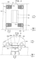
FIG. 2 is a plan view illustrating a vehicle stop area in the battery replacing device; -
FIG. 3 is a diagram schematically illustrating a configuration of a battery placement table and a lift unit; -
FIG. 4 is a perspective view schematically illustrating the configuration of the battery placement table and the lift unit; -
FIG. 5 is a bottom view of an electrified vehicle; -
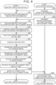
FIG. 6 is a flowchart showing each step carried out by the battery replacing device; -
FIG. 7 is a diagram schematically illustrating a state in which the battery placement table and the electrified vehicle are positioned relative to each other; -
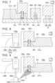
FIG. 8 is a diagram schematically illustrating a configuration of a cleansing unit; -
FIG. 9 is a diagram schematically illustrating the configuration of the cleansing unit; -
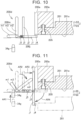
FIG. 10 is a diagram schematically illustrating a configuration of a modification of the cleansing unit; and -
FIG. 11 is a diagram schematically illustrating the configuration of the modification of the cleansing unit. - An embodiment of the present disclosure will be described below in detail with reference to the drawings. The same or corresponding parts are denoted by the same signs throughout the drawings, and description thereof will not be repeated.
-
FIG. 1 is a diagram illustrating abattery replacing device 100 and anelectrified vehicle 200 according to the present embodiment. Thebattery replacing device 100 is a device for replacing a battery (used battery) 201 attached to theelectrified vehicle 200 with a battery (new battery) 101 that is charged. Thebattery 201 and thebattery 101 are examples of a "first battery" and a "second battery" of the present disclosure, respectively. - As illustrated in
FIG. 3 , theelectrified vehicle 200 has avehicle body 200a and acleansing unit 200d. - The
vehicle body 200a has a mountingportion 200c in which thebatteries FIG. 3 , themounting portion 200c has a shape that is recessed upward from alower face 200b of thevehicle body 200a. Thebatteries mounting portion 200c by fastening members 205 (seeFIGS. 7 and 8 ) such as bolts or the like. - The
cleansing unit 200d cleanses thefastening members 205. As illustrated inFIGS. 8 and 9 , thecleansing unit 200d has aspray unit 200e, asupply unit 200f, and acover 200h. - As illustrated in
FIG. 9 , thespray unit 200e sprays a cleansing fluid (air, cleansing liquid, or the like) F that is capable of cleansing the fasteningmember 205, toward the fasteningmember 205. Thespray unit 200e is movable in an up-down direction between a spraying position (position illustrated inFIG. 9 ) and a stored position (position illustrated inFIG. 8 ). The spraying position is a position where the cleansing fluid F can be sprayed toward the fasteningmember 205 from below. The stored position is a position where thespray unit 200e is stowed inside thevehicle body 200a. As illustrated inFIG. 9 , thelower face 200b of thevehicle body 200a is provided with an opening 200b1 that enables thespray unit 200e to pass therethrough. - The
supply unit 200f supplies the cleansing fluid to thespray unit 200e. Thesupply unit 200f includes apump 200g that feeds the cleansing fluid towards thespray unit 200e. Thespray unit 200e moves from the stored position to the spraying position, under pressure of the cleansing fluid that is generated by driving thepump 200g. Note that when thepump 200g is stopped, thespray unit 200e returns from the spraying position to the stored position under a biasing force of a biasing member (omitted from illustration) that is provided in thesupply unit 200f. - The
cover 200h has a shape that closes the opening 200b1 formed in thelower face 200b of thevehicle body 200a. Thecover 200h is fixed to a lower face of thespray unit 200e. Thecover 200h closes the opening 200b1 when thespray unit 200e is located at the stored position. - The
battery replacing device 100 includes abattery replacing station 100a, astorage compartment 100b, and anunderfloor area 100c. - The
battery replacing station 100a is a station where removal of thebattery 201 from theelectrified vehicle 200 and attachment of thebattery 101 to the electrifiedvehicle 200 are performed. Thebattery replacing station 100a is provided with anentrance 102 from which theelectrified vehicle 200 enters and exits. - The
storage compartment 100b stores batteries 101 that are charged. Thestorage compartment 100b is built annexed to thebattery replacing station 100a. Acharging facility 51 capable of charging thebattery 201 removed from the electrifiedvehicle 200 is provided in thestorage compartment 100b. Thebattery 201 is charged by thecharging facility 51 in thestorage compartment 100b. Thebattery 101 charged in thestorage compartment 100b, i.e., thebattery 101 that is charged is transported to the electrifiedvehicle 200 after being moved to atemporary storage site 40 provided in theunderfloor area 100c. - The
underfloor area 100c is provided below thebattery replacing station 100a and thestorage compartment 100b. Theunderfloor area 100c is provided with a battery placement table 34, alift unit 35, afirst transporting unit 36, and asecond transporting unit 37, which will be described later. - The
battery replacing device 100 includes acontrol device 10 and adrive device 30. - The
control device 10 includes aprocessor 11,memory 12, and acommunication unit 13. Thememory 12 stores programs to be executed by theprocessor 11, as well as information used by the programs (e.g., maps, mathematical expressions, and various types of parameters). Theprocessor 11 controls thedrive device 30, which will be described in detail later. - The
communication unit 13 includes various types of communication interfaces. Theprocessor 11 controls thecommunication unit 13. Thecommunication unit 13 communicates with a data communication module (DCM) and so forth of the electrifiedvehicle 200. Bi-directional communication can be performed between thecommunication unit 13 and the electrifiedvehicle 200. Note that thecommunication unit 13 may communicate with a mobile terminal or the like owned by a user of the electrifiedvehicle 200. - As illustrated in
FIG. 2 , thebattery replacing device 100 is provided with avehicle stop area 103. When the user performs an operation to instruct starting of battery replacement work at a navigation system (omitted from illustration) of the electrifiedvehicle 200 in a state in which the electrifiedvehicle 200 is stopped in thevehicle stop area 103, thecommunication unit 13 receives an instruction signal to start the battery replacement work from the electrifiedvehicle 200. Theprocessor 11 starts controlling the battery replacement work based on reception of the instruction signal by thecommunication unit 13. Note that the electrifiedvehicle 200 stops in thevehicle stop area 103 such that a front-rear direction matches an X direction and a right-left direction matches a Y direction. - The
drive device 30 includes wheel securing units 31 (seeFIG. 2 ), a shutter 32 (seeFIG. 2 ), the battery placement table 34 (seeFIG. 1 ), the lift unit 35 (seeFIG. 1 ), the first transporting unit 36 (SeeFIG. 1 ), and the second transporting unit 37 (SeeFIG. 1 ). - Referring to
FIG. 2 again, four of thewheel securing units 31 are provided in thevehicle stop area 103. Thewheel securing units 31 are provided so as to correspond to each of fourwheels 202 of electrifiedvehicle 200. - Each of the
wheel securing units 31 includes apressing member 31a and alateral roller portion 31b. Thepressing members 31a move thewheels 202 by pressing thewheels 202 from the outer side thereof (sideward). Thepressing members 31a are disposed straddling thelateral roller portions 31b. Thus, thewheels 202 are positioned by thewheel securing units 31. - The
lateral roller portions 31b are made up of a plurality of rollers of which the rotation axes extend in the X direction. The rollers of thelateral roller portions 31b are arrayed in the Y direction. Rotating the rollers of thelateral roller portions 31b moves thepressing members 31a in the Y direction. - As illustrated in
FIG. 2 , theshutter 32 is provided in thevehicle stop area 103. Theshutter 32 is configured to be capable of opening and closing anopening portion 32a formed in a floor surface FL of thevehicle stop area 103. Theshutter 32 can be switched between an open state in which theopening portion 32a is open and a closed state in which theopening portion 32a is closed. - The
lift unit 35 can move in the up-down direction through theopening portion 32a, between a position higher than the floor surface FL and a position lower than the floor surface FL. As illustrated inFIG. 3 , thelift unit 35 can rise to a position where thewheels 202 of the electrifiedvehicle 200 are lifted off of the floor surface FL, in a state of holding the electrifiedvehicle 200 from below. Thelift unit 35 raises the electrified vehicle so that a height H of thelower face 200b of thevehicle body 200a from the floor surface FL reaches a predetermined height. - The
lift unit 35 includes a pair of liftingbars 35a that are disposed spaced apart in a direction (Y direction) orthogonal to the up-down direction. Each of the liftingbars 35a is provided with two projectingportions 35b projecting upward. The electrifiedvehicle 200 is supported from below by two projectingportions 35b of each of the lifting bars 35a, (i.e., four projectingportions 35b). - The battery placement table 34 is disposed below the
battery replacing station 100a, more specifically below theopening portion 32a. The battery placement table 34 is capable of having thebatteries FIG. 4 , the battery placement table 34 has abase portion 34e, twopositioning pins 34a, four locking/unlockingtools 34b,roller portions 34c, and astopper 34f. - The
base portion 34e is disposed between the liftingbars 35a. Thebase portion 34e is movable in the up-down direction. Thebase portion 34e is formed having a form of a flat plate. Thebase portion 34e has an outer shape that is larger than the outer shape of thebatteries base portion 34e is configured to be movable in a lateral direction below the electrifiedvehicle 200. Specifically, thebase portion 34e is movable in the X direction (X1 direction, X2 direction) and the Y direction (Y1 direction, Y2 direction). Thebase portion 34e is rotatable so as to change the orientation (angle) thereof in the XY plane. Note that each of the lifting bars 35a may also be movable in the same manner as thebase portion 34e. - Each
positioning pin 34a is provided on thebase portion 34e. Eachpositioning pin 34a is a part for performing positioning of thevehicle body 200a of the electrifiedvehicle 200 and thebase portion 34e. Onepositioning pin 34a is provided at one end portion of thebase portion 34e in a direction parallel to a vehicle width direction (Y direction). Theother positioning pin 34a is provided at the other end portion of thebase portion 34e in the direction parallel to the vehicle width direction (Y direction). - As illustrated in
FIG. 5 , thelower face 200b of thevehicle body 200a of the electrifiedvehicle 200 is provided with pin insertion holes 208 into which the positioning pins 34a are inserted. Eachpositioning pin 34a is insertable into a corresponding one of the pin insertion holes 208. - Each locking/unlocking
tool 34b is movable in the up-down direction. Each locking/unlockingtool 34b is movable in the up-down direction with respect to thebase portion 34e. As illustrated inFIG. 4 , each locking/unlockingtool 34b is disposed on an inward side of the positioning pins 34a in the Y direction. Each locking/unlockingtool 34b is disposed on an outer side of thebase portion 34e in the X direction. - As illustrated in
FIG. 5 , thebattery 201 has abottom face 201e, and thebottom face 201e is provided with tool insertion holes 201f into which the locking/unlockingtools 34b are inserted. Tool insertion holes are also provided on a bottom face of thebattery 101. Each locking/unlockingtool 34b can be inserted into a corresponding one of the tool insertion holes. - The
roller portions 34c are provided in thebase portion 34e. Theroller portions 34c are rotatable about rotation axes extending in the X direction. Rotating theroller portions 34c in one direction moves thebatteries base portion 34e to one side in the Y direction (e.g., to the Y1 side), and rotating theroller portions 34c in the other direction moves thebatteries base portion 34e to the other side in the Y direction. - A
marker 34d is provided at a distal end portion of eachpositioning pin 34a. Themarker 34d is made up of a light emitter such as a light-emitting diode (LED) or the like. Themarker 34d may have an upwardly tapered form. - The
stopper 34f is provided on thebase portion 34e. Thestopper 34f will be described later. - Now, referring to
FIG. 1 again, the first transportingunit 36 transports thebattery 101 stored in thestorage compartment 100b toward the battery placement table 34. Specifically, theunderfloor area 100c is provided with thetemporary storage site 40 for temporarily storing the chargedbattery 101 that was stored in thestorage compartment 100b, and the first transportingunit 36 can transport thebattery 101 from thetemporary storage site 40 toward the battery placement table 34. Note that the first transportingunit 36 may be of a conveyor belt type, for example. - The second transporting
unit 37 transports the usedbattery 201, which is removed from the electrifiedvehicle 200 and placed on the battery placement table 34, away from the battery placement table 34. Specifically, in theunderfloor area 100c, astorage space 42 for storing thebattery 201 is provided at a position spaced apart from thestorage compartment 100b, and the second transportingunit 37 transports thebattery 201 from the battery placement table 34 toward thestorage space 42, in the transporting direction in which the first transportingunit 36 transports thebattery 101 toward the battery placement table 34 (Y2 direction). The first transportingunit 36 and the second transportingunit 37 are disposed so as to be arrayed on the same straight line. Note that the second transportingunit 37 may also be of a conveyor belt type, for example. - A charging
facility 52 capable of charging thebattery 201 is provided in thestorage space 42. Thebattery 201 stored in thestorage space 42 is transported to thestorage compartment 100b by a transport unit (omitted from illustration) after charging by the chargingfacility 52 is completed, or during charging thereof. Note that the transport unit may be made up of the first transportingunit 36 and the second transportingunit 37. - Now, description of the
stopper 34f will be given. Thestopper 34f is provided at a portion of thebase portion 34e that is on a downstream side from theroller portions 34c in the transporting direction (Y2 direction). Thestopper 34f abuts thebattery 101, which is transported from the first transportingunit 36 to thebase portion 34e, from a direction opposite to the transporting direction. The position of thestopper 34f in a direction parallel to the transporting direction (Y direction) is set in accordance with the position of thebattery 201 to be mounted in electrifiedvehicle 200. Thestopper 34f is movable in the up-down direction between a projecting position (position illustrated inFIG. 4 ) projecting upward from thebase portion 34e so as to abut thebatteries base portion 34e, so as to enable movement of the usedbattery 201 from thebase portion 34e to the second transportingunit 37. - Movement of the
stopper 34f between the projecting position and the sunken position is controlled by theprocessor 11 of thecontrol device 10. Theprocessor 11 positions thestopper 34f at the projecting position when the chargedbattery 101 moves from the first transportingunit 36 to thebase portion 34e, and positions thestopper 34f at the sunken position when the usedbattery 201 moves from thebase portion 34e to the second transportingunit 37. - Next, a battery replacement method using the
battery replacing device 100 will be described with reference to the flowchart (sequence diagram) ofFIG. 6 . - First, in step S21, the electrified
vehicle 200 transmits information about the electrifiedvehicle 200 and information about thebattery 201 to thecommunication unit 13 of thebattery replacing device 100. For example, an operation is made at an automotive navigation system (omitted from illustration) of the electrifiedvehicle 200, to transmit each of the above information, thereby transmitting each of the above information to thecommunication unit 13. The electrifiedvehicle 200 transmits each piece of the above information before entering thebattery replacing device 100. Note that each piece of the above information may be transmitted after the electrifiedvehicle 200 enters thebattery replacing device 100. - Next, in step S1, the
communication unit 13 of thebattery replacing device 100 acquires, through communication, the information regarding the electrifiedvehicle 200 and the information regarding thebattery 201, transmitted from the electrifiedvehicle 200 in step S21. Each piece of the acquired information is stored in the memory 12 (seeFIG. 1 ). - The
communication unit 13 may also acquire information regarding capacity (charge capacity) of thebattery 201 and the state of charge (SOC) of thebattery 201. - Next, in step S22, the electrified
vehicle 200 that is stopped in thevehicle stop area 103 transmits an instruction signal to thecommunication unit 13, to start battery replacement work. - Next, in step S2, the
communication unit 13 receives the instruction signal transmitted from the electrifiedvehicle 200 in step S22. Note that in step S2, upon receiving the instruction signal, theprocessor 11 may transmit an instruction message or the like to the user of electrifiedvehicle 200 through thecommunication unit 13, for turning ignition power to an off state. - Next, in step S3, the
processor 11 adjusts the positions of the wheel securing units 31 (seeFIG. 2 ) based on the information (vehicle information and battery information) acquired through thecommunication unit 13 in step S1. Note that theprocessor 11 may control each of the fourwheel securing units 31 independently of each other. - Accordingly, the position and the orientation of the
vehicle body 200a in the lateral direction are adjusted, and also the position and the orientation of thebattery 201 in the lateral direction are adjusted. As a result, thebattery 201 is moved to a predetermined position above theopening portion 32a. - Next, in step S4, the
processor 11 places theshutter 32 in an open state and raises thelift unit 35 in the state in which theshutter 32 is open. Thus, after passing through theopening portion 32a, thelift unit 35 lifts the electrifiedvehicle 200 so that the height H of thelower face 200b of thevehicle body 200a from the floor surface FL reaches the predetermined height (seeFIG. 3 ). - The
cleansing unit 200d cleanses thefastening members 205 either by the time step S4 is completed, or before step S5 is started. First, thepump 200g of thesupply unit 200f is driven. Thespray unit 200e moves from the stored position to the spraying position under the pressure of the cleansing fluid F generated thereby, and sprays the cleansing fluid F toward thefastening members 205. Accordingly, thefastening members 205 are cleansed, so that the foreign matter adhering to thefastening members 205 or the vicinity thereof (tool insertion holes 201f and so forth) is removed. Note that cleansing of thefastening members 205 may be performed inside thebattery replacing station 100a or may be performed outside of thebattery replacing station 100a. - Next, in step S5, the used
battery 201 is removed from thevehicle body 200a of the electrifiedvehicle 200. First, theprocessor 11 raises the battery placement table 34. Thus, as illustrated inFIG. 7 , the positioning pins 34a are inserted into the pin insertion holes 208 formed in thelower face 200b of thevehicle body 200a, and also the locking/unlockingtools 34b are inserted into thetool insertion holes 201f formed in thebottom face 201e of thebattery 201, and thebase portion 34e either abuts or approaches thebottom face 201e of thebattery 201. As a result, the battery placement table 34 is positioned with respect to the electrified vehicle 200 (i.e., as to the battery 201). Note that at this time, the positioning pins 34a are inserted into the pin insertion holes 208 prior to the locking/unlockingtools 34b being inserted into thetool insertion holes 201f. - Next, the
processor 11 raises the locking/unlockingtools 34b in a state in which the locking/unlockingtools 34b are inserted into thetool insertion holes 201f. Theprocessor 11 then drives (rotates) the locking/unlockingtools 34b inserted into thetool insertion holes 201f. This unlocks thefastening members 205 in thetool insertion holes 201f. As a result, thebattery 201 is removed from thevehicle body 200a, and placed on thebase portion 34e. Note that the timing at which the positioning pins 34a are inserted into the pin insertion holes 208 and the timing at which the locking/unlockingtools 34b are inserted into thetool insertion holes 201f may be the same as each other. - Next, in step S6, the
battery 201 removed from thevehicle body 200a in step S5 is transported to the storage space 42 (seeFIG. 1 ). First, theprocessor 11 lowers the battery placement table 34, on which thebattery 201 is placed, to the height position of the second transporting unit 37 (seeFIG. 1 ). Next, theprocessor 11 lowers thelift unit 35 to a position below the battery placement table 34 (e.g., the position illustrated inFIG. 1 ). Thus, thevehicle body 200a is no longer held by thelift unit 35, and consequently the electrifiedvehicle 200 is placed on the floor surface FL of thevehicle stop area 103. At this time, theprocessor 11 positions thestopper 34f at the sunken position. Subsequently, theprocessor 11 drives theroller portions 34c (seeFIG. 4 ) of the battery placement table 34 so that thebattery 201 moves over thebase portion 34e, in the transporting direction (Y2 direction). Thus, thebattery 201 placed on thebase portion 34e moves over thebase portion 34e toward the second transportingunit 37 without abutting thestopper 34f, and is relocated from thebase portion 34e to the second transportingunit 37. Thebattery 201 is transported to thestorage space 42 by the second transportingunit 37 and stored therein. Thisbattery 201 may be charged at the chargingfacility 52 in thestorage space 42. Note that thebattery 201 is transported to thestorage compartment 100b by the transporting unit, either after charging is completed or during charging. - Next, in step S7, the
processor 11 transports the chargedbattery 101 stored in thestorage compartment 100b to the battery placement table 34. Specifically, after transporting thebattery 101 from thestorage compartment 100b to thetemporary storage site 40 in theunderfloor area 100c, theprocessor 11 transports thebattery 101 in a transporting direction from thetemporary storage site 40 to the battery placement table 34 (Y2 direction) by the first transportingunit 36. At this time, theprocessor 11 positions thestopper 34f at the projecting position. Upon thebattery 101 being relocated from the first transportingunit 36 to thebase portion 34e, theprocessor 11 drives theroller portions 34c so that thebattery 101 moves over thebase portion 34e in the transporting direction. As a result, thebattery 101 abuts thestopper 34f and thus stops at the predetermined position on thebase portion 34e. - Next, in step S8, the
processor 11 performs control to attach thebattery 101 that is charged to thevehicle body 200a. Specifically, theprocessor 11 raises thelift unit 35 so that the height H of thelower face 200b of thevehicle body 200a from the floor surface FL of thevehicle stop area 103 reaches the predetermined height. - Subsequently, the
processor 11 raises the battery placement table 34. Accordingly, the positioning pins 34a are inserted into the pin insertion holes. Theprocessor 11 raises the locking/unlockingtools 34b in this state. Thus, the locking/unlockingtools 34b are inserted into the tool insertion holes of thebattery 101. Theprocessor 11 then drives (rotates) the locking/unlockingtools 34b. Accordingly, the bolts inside the tool insertion holes are locked. Upon detection being made that all the bolts are locked, the vehicle-side connector (omitted from illustration) and the connector (omitted from illustration) of thebattery 101 are locked. As a result, attachment of thebattery 101 that is charged, to thevehicle body 200a, is completed. - Next, in step S9, the
processor 11 lowers the battery placement table 34 and thelift unit 35, and performs retraction thereof from the electrifiedvehicle 200. Thereafter, theprocessor 11 places theshutter 32 in a closed state (seeFIG. 2 ). - Next, in step S10, the
processor 11 notifies the electrifiedvehicle 200 through thecommunication unit 13 that the battery replacement work has been completed. - In the following step S23, the electrified
vehicle 200 receives the notification transmitted from thecommunication unit 13 of thebattery replacing device 100 in step S10. Thus, the electrifiedvehicle 200 is brought into a state in which the ignition power can be turned on. Thereafter, the processing ends. - Although the above-described embodiment illustrates an example in which the position of the
drive device 30 is adjusted based on information on each of the electrifiedvehicle 200 and thebattery 201, the present disclosure is not limited to this. The position of thedrive device 30 may be adjusted based on information regarding either one of the electrifiedvehicle 200 and thebattery 201. - As described above, the electrified
vehicle 200 according to the present embodiment includes thecleansing unit 200d for cleansing thefastening members 205, and accordingly the locking/unlockingtools 34b for removing thefastening members 205 can effectively fit thefastening members 205. - In the above embodiment, the
cleansing unit 200d may be provided in thebattery replacing station 100a. In this case, thecleansing unit 200d is provided on the floor surface FL of thevehicle stop area 103, the battery placement table 34, or the like. - Also, in the above embodiment, the
cleansing unit 200d may have aslider 200j and acam lever 200m, as illustrated inFIGS. 10 and 11 . - The
slider 200j is provided on thevehicle body 200a. Theslider 200j is movable with respect to thevehicle body 200a in a direction toward the battery 201 (right direction inFIGS. 10 and 11 ) and in a direction away from the battery 201 (left direction inFIGS. 10 and 11 ). Theslider 200j has a first slider portion j1, a second slider portion j2, a rotation shaft j3, a brush portion j4, and a biasing member j5. - The first
slider portion j 1 is disposed in thevehicle body 200a, with an attitude that is parallel to thelower face 200b of thevehicle body 200a. - The second slider portion j2 is disposed with an attitude that is orthogonal to the first
slider portion j 1. - The rotation shaft j3 links the first slider portion j1 and the second slider portion j2. More specifically, the rotation shaft j3 links a basal end portion of the first
slider portion j 1 and a lower end portion of the second slider portion j2, so as to enable pivoting of the first slider portion j1 about the rotation shaft j3. Thevehicle body 200a is provided with a guide slit (omitted from illustration) that guides the rotation shaft j3 in a longitudinal direction (right-left direction inFIG. 10 ) of the first slider portion j1, and the rotation shaft j3 is movable along this guide slit. - The brush portion j4 is provided at a distal end portion of the first
slider portion j 1. The brush portion j4 can clean thefastening members 205. The brush portion j4 has a shape extending upward from the distal end portion of the firstslider portion j 1. - The biasing member j5 connects the
vehicle body 200a and the rotation shaft j3, and biases the rotation shaft j3 in an orientation away from the battery with respect to thevehicle body 200a. Note that the biasing member j5 may be connected to the second slider portion j2. - The
cam lever 200m drives the brush portion j4. Specifically, thecam lever 200m presses theslider 200j by being pushed by apositioning pin 34g provided on thebase portion 34e. Note that thepositioning pin 34a may make up thepositioning pin 34g. Thecam lever 200m has a first lever portion m1, a second lever portion m2, and a rotation shaft m3. - The first lever portion m1 is disposed in the
vehicle body 200a, with an attitude that is parallel to thelower face 200b of thevehicle body 200a. The first lever portion m1 is a portion that is pressed by thepositioning pin 34g. - The second lever portion m2 is orthogonal to the first lever portion m1. The second lever portion m2 can press the second slider portion j2.
- The rotation shaft m3 links the first lever portion m1 and the second lever portion m2. The rotation shaft m3 links the first lever portion m1 and the second lever portion m2 such that the attitude of the second lever portion m2 with respect to the first lever portion m1 is maintained.
- Upon the
positioning pin 34g pressing the first lever portion m1 upward, as indicated by arrow AR1 inFIG. 11 , the second lever portion m2 pivots about the rotation axis m3, as indicated by arrow AR2. Then, due to the second slider portion j2 being pushed by this second lever portion m2, theslider 200j moves in the direction toward thebattery 201 against the biasing force of the biasing member, as indicated by arrow AR3. During this movement, thefastening member 205 is cleaned by the brush portion j4. Note that inFIG. 11 , thepositioning pin 34g, theslider 200j, and thecam lever 200m, prior to movement, are indicated by long dashed short dashed lines. - When the second slider portion j2 comes into contact with a side face of the
vehicle body 200a, the firstslider portion j 1 pivots about the rotation axis j3, as indicated by arrow AR4. At this time, the firstslider portion j 1 pivots from the movement path of thebattery 201 to a retracted position. Accordingly, a situation in which removal of thebattery 201 from thevehicle body 200a is hindered by the firstslider portion j 1 and the brush portion j4 can be circumvented. Note that inFIG. 11 , the firstslider portion j 1 and the brush portion j4, immediately prior to pivoting about the rotation axis m3, are indicated by long dashed double-short dashed lines. - Thereafter, when the
positioning pin 34g descends together with thebase portion 34e, theslider 200j moves toward thecam lever 200m under the biasing force of the biasing member j5. At this time, the first slider portion j1 returns to the initial attitude (the attitude indicated inFIG. 10 ) by pivoting about the rotation axis j3, and thecam lever 200m also returns to the initial attitude (the attitude illustrated inFIG. 10 ) by being pressed by the second slider portion j2. - It will be appreciated by those skilled in the art that the exemplary embodiment described above is a specific example of the aspects described below.
- A vehicle, comprising: a vehicle body including a mounting portion that is configured to mount a battery, the battery that is disposed in the mounting portion, a fastening member that fastens the battery to the mounting portion, and a cleansing unit that cleanses the fastening member.
- This vehicle has the cleansing unit for cleansing the fastening member, and accordingly, a tool for removing the fastening member is effectively fit to the fastening member when the battery is replaced.
- The vehicle according to
Form 1, wherein the cleansing unit includes a spray unit for spraying the fastening member with a cleansing fluid for cleansing the fastening member, and a supply unit for supplying the cleansing fluid to the spray unit. - The vehicle according to
Form 2, wherein the spray unit is configured to move in an up-down direction, between a spraying position for spraying the cleansing fluid toward the fastening member from below, and a stored position of being stored in the vehicle body. - In this Form, adhesion of foreign matter to the spray unit is suppressed by positioning the spray unit at the stored position when the cleansing fluid is not being sprayed by the spray unit.
- The vehicle according to
Form 3, wherein the supply unit includes a pump for feeding the cleansing fluid towards the spray unit, and wherein the spray unit moves from the stored position to the spraying position under pressure of the cleansing fluid generated by driving the pump. - In this Form, no dedicated member for moving the spray unit is required, and accordingly the configuration of the cleansing unit is simplified.
- The vehicle according to
Form 1, wherein the cleansing unit includes a brush portion configured to clean the fastening member, and a cam lever for driving the brush portion, and wherein the cam lever drives the brush portion by being pressed when the battery is replaced. - In this Form, the fastening member is cleaned by the brush portion when the battery is replaced, and accordingly the tool for removing the fastening member is effectively fitted to the fastening member.
- The vehicle according to
Form 5, wherein the brush portion moves to a position retracted from a movement path of the battery, following cleaning of the fastening member. - In this aspect, when the battery is removed after cleaning the fastening member, interference of the brush portion with the battery is circumvented.
- The embodiment disclosed herein should be considered to be exemplary and not restrictive in all respects. The scope of the invention is set forth in the claims, rather than in the above description of the embodiments, and further is intended to include all modifications within the meaning and the scope equivalent to the claims.
Claims (7)
- A vehicle (200) comprising:a battery (201);a vehicle body (200a) including a mounting portion that is configured to mount the battery (201);a fastening member (205) for fastening the battery (201) to the mounting portion (200c); anda cleansing unit (200d) for cleansing the fastening member (205).
- The vehicle (200) according to claim 1, wherein the cleansing unit (200d) includesa spray unit (200e) for spraying the fastening member (205) with a cleansing fluid for cleansing the fastening member (205), anda supply unit (200f) for supplying the cleansing fluid to the spray unit (200e).
- The vehicle (200) according to claim 2, wherein the spray unit (200e) is configured to move in an up-down direction, between a spraying position for spraying the cleansing fluid toward the fastening member (205) from below, and a stored position of being stored in the vehicle body (200a).
- The vehicle (200) according to claim 3,wherein the supply unit (200f) includes a pump for feeding the cleansing fluid towards the spray unit (200e), andwherein the spray unit (200e) moves from the stored position to the spraying position under pressure of the cleansing fluid generated by driving the pump.
- The vehicle according to any of claims 1 to 4,wherein the cleansing unit (200d) includes a brush portion (j4) configured to clean the fastening member (205), and a cam lever (200m) for driving the brush portion (j4), andwherein the cam lever (200m) drives the brush portion (j4) by being pressed when the battery is replaced.
- The vehicle according to claim 5, wherein the brush portion (j4) moves to a position retracted from a movement path of the battery, following cleaning of the fastening member (205).
- The vehicle according to claim 2 taken in combination with any of claims 1 to 6, wherein the cleansing fluid for cleansing is air or a washing liquid.
Applications Claiming Priority (1)
| Application Number | Priority Date | Filing Date | Title |
|---|---|---|---|
| JP2022194396A JP7746975B2 (en) | 2022-12-05 | 2022-12-05 | vehicle |
Publications (1)
| Publication Number | Publication Date |
|---|---|
| EP4382352A1 true EP4382352A1 (en) | 2024-06-12 |
Family
ID=88511244
Family Applications (1)
| Application Number | Title | Priority Date | Filing Date |
|---|---|---|---|
| EP23203661.6A Pending EP4382352A1 (en) | 2022-12-05 | 2023-10-13 | Vehicle |
Country Status (5)
| Country | Link |
|---|---|
| US (1) | US20240182000A1 (en) |
| EP (1) | EP4382352A1 (en) |
| JP (1) | JP7746975B2 (en) |
| KR (1) | KR20240083809A (en) |
| CN (1) | CN118144535A (en) |
Families Citing this family (1)
| Publication number | Priority date | Publication date | Assignee | Title |
|---|---|---|---|---|
| CN112140939A (en) * | 2020-06-24 | 2020-12-29 | 武汉蔚来能源有限公司 | Battery changing platform, battery changing station and battery changing method |
Citations (6)
| Publication number | Priority date | Publication date | Assignee | Title |
|---|---|---|---|---|
| CN106627235A (en) | 2017-01-04 | 2017-05-10 | 上海蔚来汽车有限公司 | Full-automatic dust prevention system used for electric vehicle quick-change connector |
| WO2018126660A1 (en) * | 2017-01-04 | 2018-07-12 | 上海蔚来汽车有限公司 | Cleaning device for electric automobile and battery swapping system comprising same |
| US20180354378A1 (en) * | 2014-12-18 | 2018-12-13 | Kuka Systems Gmbh | Method For Changing Vehicle Energy Stores, And An Energy Store Changing Device |
| CN208277831U (en) * | 2018-04-28 | 2018-12-25 | 福州市长乐区三互信息科技有限公司 | A kind of new-energy automobile being conveniently replaceable storage battery |
| CN111889403A (en) * | 2020-07-09 | 2020-11-06 | 浙江吉智新能源汽车科技有限公司 | Cleaning system, battery cleaning device and cleaning method |
| CN112428808A (en) * | 2020-10-14 | 2021-03-02 | 刘万辉 | Battery for clean energy automobile with independently dust removal function |
Family Cites Families (10)
| Publication number | Priority date | Publication date | Assignee | Title |
|---|---|---|---|---|
| JPS54179643U (en) * | 1978-06-08 | 1979-12-19 | ||
| JPS5974159U (en) * | 1982-11-10 | 1984-05-19 | ナショナル住宅産業株式会社 | Tire cleaning device for vehicles |
| JPH078126U (en) * | 1993-07-12 | 1995-02-03 | 日産ディーゼル工業株式会社 | Vehicle tire cleaning equipment |
| JP2006256364A (en) | 2005-03-15 | 2006-09-28 | Koito Mfg Co Ltd | Washing device of lighting lamp for vehicle |
| JP2011148382A (en) | 2010-01-21 | 2011-08-04 | Stanley Electric Co Ltd | Cleaning device of lighting fixture for vehicle |
| JP2013121209A (en) | 2011-12-06 | 2013-06-17 | Sumitomo Electric Ind Ltd | Non contact power reception device |
| SE540236C2 (en) | 2016-09-02 | 2018-05-08 | Scania Cv Ab | Method and system for clearing a charging adapter for charging a plug-in electrical vehicle |
| CN107054303A (en) | 2017-01-04 | 2017-08-18 | 上海蔚来汽车有限公司 | Electric system is changed for the cleaning equipment of electric automobile and comprising the cleaning equipment |
| JP7413724B2 (en) | 2019-11-06 | 2024-01-16 | 株式会社デンソー | Foreign matter removal system for current collectors installed in vehicles |
| US11623616B2 (en) | 2020-05-08 | 2023-04-11 | Toyota Motor Engineering & Manufacturing North America, Inc. | Vehicles including sprayer assemblies for vehicle bumpers |
-
2022
- 2022-12-05 JP JP2022194396A patent/JP7746975B2/en active Active
-
2023
- 2023-10-12 KR KR1020230135960A patent/KR20240083809A/en not_active Ceased
- 2023-10-13 EP EP23203661.6A patent/EP4382352A1/en active Pending
- 2023-10-23 US US18/382,682 patent/US20240182000A1/en active Pending
- 2023-10-31 CN CN202311434667.8A patent/CN118144535A/en active Pending
Patent Citations (6)
| Publication number | Priority date | Publication date | Assignee | Title |
|---|---|---|---|---|
| US20180354378A1 (en) * | 2014-12-18 | 2018-12-13 | Kuka Systems Gmbh | Method For Changing Vehicle Energy Stores, And An Energy Store Changing Device |
| CN106627235A (en) | 2017-01-04 | 2017-05-10 | 上海蔚来汽车有限公司 | Full-automatic dust prevention system used for electric vehicle quick-change connector |
| WO2018126660A1 (en) * | 2017-01-04 | 2018-07-12 | 上海蔚来汽车有限公司 | Cleaning device for electric automobile and battery swapping system comprising same |
| CN208277831U (en) * | 2018-04-28 | 2018-12-25 | 福州市长乐区三互信息科技有限公司 | A kind of new-energy automobile being conveniently replaceable storage battery |
| CN111889403A (en) * | 2020-07-09 | 2020-11-06 | 浙江吉智新能源汽车科技有限公司 | Cleaning system, battery cleaning device and cleaning method |
| CN112428808A (en) * | 2020-10-14 | 2021-03-02 | 刘万辉 | Battery for clean energy automobile with independently dust removal function |
Also Published As
| Publication number | Publication date |
|---|---|
| KR20240083809A (en) | 2024-06-12 |
| CN118144535A (en) | 2024-06-07 |
| US20240182000A1 (en) | 2024-06-06 |
| JP7746975B2 (en) | 2025-10-01 |
| JP2024081000A (en) | 2024-06-17 |
Similar Documents
| Publication | Publication Date | Title |
|---|---|---|
| EP4382352A1 (en) | Vehicle | |
| US5538809A (en) | Automatic coupling system for traction batteries | |
| CN105813934A (en) | Conveying vehicle on which a vehicle body is arranged during the entire final assembly thereof, manufacturing plant, and manufacturing method | |
| EP2856268A2 (en) | Methods for using an automated guided cart | |
| US6896468B2 (en) | Battery interchange system for battery powered floor maintenance equipment | |
| CN110677998B (en) | PCB board automatic disassembly equipment | |
| CN116981604A (en) | Power exchange device and power exchange system | |
| JP2020117031A (en) | Towing vehicle system | |
| US20240181911A1 (en) | Battery Replacement Apparatus and Battery Replacement Method | |
| JP7620122B2 (en) | Working robot and component mounting system | |
| CN118078166A (en) | A cleaning base station, a sub-robot and a cleaning system | |
| JPS60106302A (en) | Power supply system for working self-traveling vehicle | |
| JP7835151B2 (en) | Electric vehicles | |
| US12583355B2 (en) | Battery replacement apparatus | |
| JPS63272436A (en) | Parts loader | |
| JP7816106B2 (en) | Battery exchange device and battery exchange method | |
| CN208961371U (en) | Automobile door plate integration tooling device | |
| US12567635B2 (en) | Vehicle with detachably mounted battery | |
| JP7845161B2 (en) | Battery replacement device and battery replacement method | |
| JP7826931B2 (en) | vehicle | |
| WO2024121672A1 (en) | Battery replacement system | |
| JPH05270331A (en) | Automatic conveyor car | |
| CN110871698A (en) | Automatic charging method for new energy automobile in comb-tooth type stereo garage | |
| CN222265185U (en) | Cleaning base station, sub-robot and cleaning system | |
| CN118163752A (en) | Battery replacement device |
Legal Events
| Date | Code | Title | Description |
|---|---|---|---|
| PUAI | Public reference made under article 153(3) epc to a published international application that has entered the european phase |
Free format text: ORIGINAL CODE: 0009012 |
|
| STAA | Information on the status of an ep patent application or granted ep patent |
Free format text: STATUS: REQUEST FOR EXAMINATION WAS MADE |
|
| 17P | Request for examination filed |
Effective date: 20231013 |
|
| AK | Designated contracting states |
Kind code of ref document: A1 Designated state(s): AL AT BE BG CH CY CZ DE DK EE ES FI FR GB GR HR HU IE IS IT LI LT LU LV MC ME MK MT NL NO PL PT RO RS SE SI SK SM TR |