JP7620122B2 - Working robot and component mounting system - Google Patents
Working robot and component mounting system Download PDFInfo
- Publication number
- JP7620122B2 JP7620122B2 JP2023564346A JP2023564346A JP7620122B2 JP 7620122 B2 JP7620122 B2 JP 7620122B2 JP 2023564346 A JP2023564346 A JP 2023564346A JP 2023564346 A JP2023564346 A JP 2023564346A JP 7620122 B2 JP7620122 B2 JP 7620122B2
- Authority
- JP
- Japan
- Prior art keywords
- work
- guided vehicle
- unit
- automated guided
- working
- Prior art date
- Legal status (The legal status is an assumption and is not a legal conclusion. Google has not performed a legal analysis and makes no representation as to the accuracy of the status listed.)
- Active
Links
Images


Classifications
-
- H—ELECTRICITY
- H05—ELECTRIC TECHNIQUES NOT OTHERWISE PROVIDED FOR
- H05K—PRINTED CIRCUITS; CASINGS OR CONSTRUCTIONAL DETAILS OF ELECTRIC APPARATUS; MANUFACTURE OF ASSEMBLAGES OF ELECTRICAL COMPONENTS
- H05K13/00—Apparatus or processes specially adapted for manufacturing or adjusting assemblages of electric components
- H05K13/02—Feeding of components
-
- G—PHYSICS
- G05—CONTROLLING; REGULATING
- G05D—SYSTEMS FOR CONTROLLING OR REGULATING NON-ELECTRIC VARIABLES
- G05D1/00—Control of position, course, altitude or attitude of land, water, air or space vehicles, e.g. using automatic pilots
- G05D1/60—Intended control result
- G05D1/656—Interaction with payloads or external entities
- G05D1/667—Delivering or retrieving payloads
-
- H—ELECTRICITY
- H05—ELECTRIC TECHNIQUES NOT OTHERWISE PROVIDED FOR
- H05K—PRINTED CIRCUITS; CASINGS OR CONSTRUCTIONAL DETAILS OF ELECTRIC APPARATUS; MANUFACTURE OF ASSEMBLAGES OF ELECTRICAL COMPONENTS
- H05K13/00—Apparatus or processes specially adapted for manufacturing or adjusting assemblages of electric components
-
- B—PERFORMING OPERATIONS; TRANSPORTING
- B60—VEHICLES IN GENERAL
- B60D—VEHICLE CONNECTIONS
- B60D1/00—Traction couplings; Hitches; Draw-gear; Towing devices
- B60D2001/001—Traction couplings; Hitches; Draw-gear; Towing devices specially adapted for use on vehicles other than cars
- B60D2001/005—Traction couplings; Hitches; Draw-gear; Towing devices specially adapted for use on vehicles other than cars for carts, scooters, or the like
-
- G—PHYSICS
- G05—CONTROLLING; REGULATING
- G05D—SYSTEMS FOR CONTROLLING OR REGULATING NON-ELECTRIC VARIABLES
- G05D2105/00—Specific applications of the controlled vehicles
- G05D2105/45—Specific applications of the controlled vehicles for manufacturing, maintenance or repairing
-
- G—PHYSICS
- G05—CONTROLLING; REGULATING
- G05D—SYSTEMS FOR CONTROLLING OR REGULATING NON-ELECTRIC VARIABLES
- G05D2107/00—Specific environments of the controlled vehicles
- G05D2107/70—Industrial sites, e.g. warehouses or factories
-
- G—PHYSICS
- G05—CONTROLLING; REGULATING
- G05D—SYSTEMS FOR CONTROLLING OR REGULATING NON-ELECTRIC VARIABLES
- G05D2109/00—Types of controlled vehicles
- G05D2109/10—Land vehicles
Landscapes
- Engineering & Computer Science (AREA)
- Manufacturing & Machinery (AREA)
- Microelectronics & Electronic Packaging (AREA)
- Aviation & Aerospace Engineering (AREA)
- Radar, Positioning & Navigation (AREA)
- Remote Sensing (AREA)
- Physics & Mathematics (AREA)
- General Physics & Mathematics (AREA)
- Automation & Control Theory (AREA)
- Automatic Assembly (AREA)
- Control Of Position, Course, Altitude, Or Attitude Of Moving Bodies (AREA)
Description
本発明は、プリント配線板等の基板に部品が実装(搭載)された部品実装基板を生産する部品実装システムに備えられる作業ロボット、及び部品実装システムに関する。 The present invention relates to a work robot and a component mounting system that are provided in a component mounting system that produces component-mounted boards in which components are mounted (mounted) on a substrate such as a printed wiring board.
プリント配線板等の基板に部品が実装(搭載)された部品実装基板を生産する生産ラインが周知である。生産ラインには複数の部品実装装置が備えられる。基板は、生産ラインに沿って搬送され、各部品実装装置で当該基板に対して部品を実装する処理が実行される。部品実装装置には、実装ヘッドと、テープフィーダ等の部品供給装置が備えられており、部品供給装置が供給する部品を実装ヘッドが吸着保持して基板上に実装する。 Production lines that produce component-mounted boards, in which components are mounted (placed) on a substrate such as a printed wiring board, are well known. The production line is equipped with multiple component mounting devices. Boards are transported along the production line, and each component mounting device mounts components on the board. The component mounting device is equipped with a mounting head and a component supplying device such as a tape feeder, and the mounting head adsorbs and holds the components supplied by the component supplying device and mounts them on the substrate.
この生産ラインでは、部品実装装置で消費される部品の補給や、生産基板の品種切替えに伴う部品供給装置の変更が必要となる。この作業は、従来、作業者が行っていたが、近年は無人の作業ロボットが担うケースが増えている。On this production line, it is necessary to replenish components consumed by the component mounting equipment and to change the component supply equipment when changing the type of board being produced. This task was traditionally performed by workers, but in recent years it has increasingly been carried out by unmanned work robots.
例えば、特許文献1には、作業ロボット(補給装置)により部品補給を行う部品実装システムの一例が開示されている。特許文献1の作業ロボットは、無人搬送車上に作業ユニット(補給ユニット)が一体に搭載された構成を有している。作業ユニットには、複数のテープフィーダが収容可能な収容部と、テープフィーダを出し入れするための送り機構とが備えられている。テープフィーダは、周知の通り、部品実装装置に備えられる部品供給装置の一つである。作業ロボットは、部品実装装置の位置まで移動して停止する。そして、送り機構を作動させ、部品実装装置にセットされている部品切れのテープフィーダと、収容部に収容されている補給用のテープフィーダとの入替作業を行う。すなわち、作業ロボットは、テープフィーダ自体を交換することにより、部品実装装置に対して部品補給を行う。For example, Patent Document 1 discloses an example of a component mounting system in which components are replenished by a work robot (supply device). The work robot in Patent Document 1 has a configuration in which a work unit (supply unit) is mounted integrally on an unmanned guided vehicle. The work unit is equipped with a storage section capable of storing multiple tape feeders and a feed mechanism for inserting and removing the tape feeders. As is well known, a tape feeder is one of the component supply devices provided in a component mounting device. The work robot moves to the position of the component mounting device and stops there. Then, the feed mechanism is activated to replace the out-of-component tape feeder set in the component mounting device with a replenishment tape feeder stored in the storage section. In other words, the work robot supplies components to the component mounting device by replacing the tape feeder itself.
記述のような従来の作業ロボットは、無人搬送車と補給ユニットとが一体であり、作業中は、無人搬送車もその場に留まることになる。よってその間は、無人搬送車を他の用途に用いることができず、無人搬送車が遊んでしまう。作業ユニットによる作業内容によっては、作業ロボットの使用頻度が極端に少ない場合もあり、この場合には無人搬送車が長期的に遊んでしまう。そのため、無人搬送車が必ずしも有効活用されているとは言えない。 In conventional work robots as described above, the automated guided vehicle and supply unit are integrated, and the automated guided vehicle also remains in place while working. As a result, the automated guided vehicle cannot be used for other purposes during that time, and ends up sitting idle. Depending on the work performed by the work unit, the frequency of use of the work robot may be extremely low, in which case the automated guided vehicle will sit idle for long periods of time. For this reason, it cannot be said that the automated guided vehicles are being used effectively.
本発明は、部品実装基板を生産する部品実装システムに備えられる作業ロボットに関して、作業ロボットおける無人搬送車をより有効に活用することが可能な技術を提供することを目的とする。 The present invention aims to provide a technology that enables more effective utilization of unmanned guided vehicles in a work robot equipped in a component mounting system that produces component-mounted boards.
本発明の一局面に係る作業ロボットは、部品実装基板を生産するための生産用装置に対して所定作業を行う作業ユニットと、当該作業ユニットを搬送する無人搬送車と、を備えた作業ロボットであって、前記無人搬送車と共に前記作業ユニットを移動させることが可能な連結状態と、前記作業ユニットから離れて前記無人搬送車が単独で走行することを許容する連結解除状態との切替えが可能な連結機構を備え、前記作業ユニットは、前記生産用装置に対する前記所定作業の実行中に当該作業ユニットから前記無人搬送車が離れた状態でも、前記所定作業を継続可能に構成されていることを特徴とする。 A working robot according to one aspect of the present invention is a working robot comprising a work unit that performs a specified task on production equipment for producing component mounting boards, and an automated guided vehicle that transports the work unit, and is equipped with a coupling mechanism that can switch between a coupled state in which the work unit can be moved together with the automated guided vehicle, and a disconnected state in which the automated guided vehicle is allowed to move independently away from the work unit, and the work unit is configured to be able to continue the specified task even when the automated guided vehicle is separated from the work unit while the specified task is being performed on the production equipment.
以下、添付図面を参照しながら本発明の好ましい実施形態について詳述する。A preferred embodiment of the present invention is described in detail below with reference to the attached drawings.
[部品実装システムの構成]
図1は、本発明に係る部品実装システム100を示すブロック図である。部品実装システム100は、プリント配線基板等の基板P上に電子部品(以下、「部品」と称する)が搭載された部品実装基板を生産するシステムである。部品実装システム100は、第1生産ライン101、第2生産ライン102、補給部6、回収部7、充電ステーション8、管理装置9及び作業ロボット20を備える。
[Component Mounting System Configuration]
1 is a block diagram showing a
第1生産ライン101及び第2生産ライン102は、生産エリアAr1に配置されており、補給部6、回収部7、充電ステーション8及び管理装置9は、準備エリアAr2に配置されている。生産エリアAr1は、部品実装基板の生産が行われるエリアであり、準備エリアAr2は、部品実装基板の生産に使用される実装部品等の消耗品や、生産品種の変更に伴い交換される機器を作業者等によって準備するエリアである。The
第1生産ライン101は、印刷装置1と、印刷検査装置2と、部品実装装置3と、外観検査装置4と、リフロー装置5とを備え、これらの装置1~5がX方向にその順番で一列に連結されて構成されている。図示を一部省略しているが、当例では、複数台の部品実装装置3が、印刷検査装置2と外観検査装置4との間に連続して配置されている。
The
印刷装置1は、基板P上の部品搭載箇所にクリーム半田を印刷する処理を実行し、印刷検査装置2は、基板P上に印刷されたクリーム半田の印刷状態を検査する処理を実行する。複数の部品実装装置3は各々、クリーム半田が印刷された基板Pの所定の実装位置に部品を実装(搭載)する処理を実行し、外観検査装置4は、基板P上に実装された部品の実装状態を検査する処理を実行する。また、リフロー装置5は、基板Pを加熱することにより半田を溶融させて部品を基板Pに接合する処理を実行する。The printing device 1 executes a process of printing cream solder at component mounting locations on the substrate P, and the
第2生産ライン102は、第1生産ライン101と基本構成は同一であり、当該第1生産ライン101に隣接して配置されている。第1生産ライン101及び第2生産ライン102では、各々、基板PがX方向に搬送されながら、印刷装置1、印刷検査装置2、部品実装装置3、外観検査装置4及びリフロー装置5において既述の各処理が実行される。これにより部品実装基板が生産される。The
補給部6は、作業者が準備した補給用の部品や機器を待機させる場所であり、回収部7は、生産ライン101、102から回収された使用済みの機器等が返却される場所である。The
作業ロボット20は、部品実装装置3と保管装置6との間を生産ライン101、102に沿って移動する自走式ロボットである。作業ロボット20は、補給用の部品や交換用の機器を補給部6から部品実装装置3に搬送して当該部品実装装置3に受け渡すとともに、使用済みの機器等を部品実装装置3から回収して回収部7に返却する機能を有する。The working
充電ステーション8は、作業ロボット20の後記無人搬送車20Vの充電用の設備である。バッテリ容量が一定量以下になった無人搬送車20Vは、この充電ステーション8に移動することで充電される。The
管理装置9は、生産ライン101、102の各装置1~5及び作業ロボット20(後記無人搬送車20V)と通信可能に接続された、例えば汎用型のコンピュータである。管理装置9は、生産計画に基づいて、生産ライン101、102の各装置1~5及び作業ロボット20を制御することにより、部品実装システム100における部品実装基板の生産を統括的に管理する。The
[部品実装装置3の構成]
図2は、部品実装システム100に備えられる部品実装装置3の平面図であり、図3は、部品実装装置3及び作業ロボット20の側面図である。図2及び図3では、部品実装装置3及び作業ロボット20は模式的に図示されている。部品実装システム100に備えられる複数の部品実装装置3各々の基本的な構成は同じである。
[Configuration of component mounting device 3]
Fig. 2 is a plan view of the
部品実装装置3は、基台10と、コンベア11と、部品供給エリア12と、ヘッドユニット15と、撮像部17とを含む。基台10は、部品実装装置3が備える各種機器の搭載ベースである。コンベア11は、基台10上にX方向に延びるように設置された、基板Pの搬送ラインであり、一対のベルト式コンベアで構成されている。コンベア11は、機外から所定の作業位置に基板Pを搬入し、実装作業後に基板Pを実装作業位置から機外へ搬出する。図2中に示す基板Pの位置が実装作業位置である。
The
部品供給エリア12は、実装部品を供給するための部品供給装置が配置されるエリアであり、Y方向においてコンベア11の両側に各々設けられている。各部品供給エリア12には、複数のテープフィーダ14がコンベア11に沿って設置されている。テープフィーダ14は、一定間隔で部品(小型の表面実装部品)が収納されたテープを繰り出しながら部品を供給するタイプの部品供給装置である。
The
当例のテープフィーダ14は、テープが巻回されたリールや当該リールからテープを繰り出す機構等が、X方向に扁平な箱形の筐体内に一体に収納された、いわゆるカセット型のテープフィーダである。テープフィーダ14は、その支持基台であるフィーダベース13上に支持されている。フィーダベース13上面には、Y方向に互いに平行に延在しかつX方向に並んだ複数の溝部(スロット13aという)が形成されている。各テープフィーダ14は、その下端部がスロット13aに挿入された状態で、フィーダベース13に支持されている。なお、各テープフィーダ14は、スロット13aに沿ってY方向に移動させることにより、フィーダベース13に対して着脱(挿抜)可能である。The
ヘッドユニット15は、ヘッドユニット駆動機構16により一定の領域内でX方向及びY方向に移動可能に設けられている。ヘッドユニット15は複数の実装ヘッド15aを備えている。各実装ヘッド15aに対して部品吸着用の負圧の供給及びその遮断が行われることにより、部品の吸着保持及びその解除が実装ヘッド15a毎に行われる。The
撮像部17は、部品の吸着保持状態を認識するために、ヘッドユニット15の各実装ヘッド15aに吸着保持された部品をその下側から撮像する。撮像部17は、カメラ及び照明装置を備えている。撮像部17は、基台10上であってコンベア11のY方向両側に各々配置されている。The
部品実装装置3では、ヘッドユニット15が部品供給エリア12と作業位置に配置された基板Pとの間を移動しながら、実装ヘッド15aにより部品供給エリア12から部品を吸着して取り出す部品吸着処理と、当該部品を基板P上に搬送して実装(搭載)する部品実装処理とが交互に実行される。これらの処理が繰り返されることで、基板P上に所定数の部品が実装される。In the
図3に示すように、各部品供給エリア12におけるフィーダベース13のY方向外側面には、各々、テープフィーダ14の入れ替え作業を行うための作業位置(フィーダ入替作業位置)に作業ロボット20を位置決めするための位置決め凸部18が設けられている。位置決め凸部18は、Y方向に間隔を隔てて少なくとも2つ設けられている。また、基台10のY方向外側面には、各々、作業ロボット20に対して電力供給を行うための給電コネクタ19が設けられている。給電コネクタ19は、前記位置決め凸部18の近傍かつ下方に配置されている。なお、フィーダ入替作業位置が複数設定される場合には、1つのフィーダ入替作業位置に対して、少なくとも2つの位置決め凸部18と一つの給電コネクタ19とが設けられる。As shown in FIG. 3, the Y-direction outer surface of the
[作業ロボット20(第1実施形態)の構成]
作業ロボット20は、既述の通り、補給用の部品や交換用の機器を補給部6からから部品実装装置3に搬送して当該部品実装装置3に受け渡すとともに、使用済みの機器等を部品実装装置3から回収して回収部7に搬送する作業を行う。以下の説明では、部品実装装置3(生産用装置)に対して部品の補給作業を行う作業ロボット20について説明する。
[Configuration of Work Robot 20 (First Embodiment)]
As described above, the working
記述の通り、テープフィーダ14は、カセット型のテープフィーダであり、テープフィーダ14において部品切れが発生した場合には、当該テープフィーダ14を交換する(入れ替える)ことにより、実質的に部品補給が行われる。そのため、作業ロボット20は、部品実装装置3との間でテープフィーダ14を入れ替えることが可能な以下の構成を備えている。As described above, the
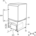
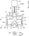
図4は、作業ロボット20を後方から視た斜視図であり、図5は、作業ロボット20のユニットベース部30を示す背面図(図3及び図4のA矢視図)である。また、図6は、作業ロボット20に備えられる無人搬送車20Vの側面図である。なお、図4中の指標のように、作業ロボット20は、ユニットベース部30において後記開口部35aが設けられている側が「後」、それとは反対側が「前」である。先に示した図3では、Y2側が「前」、Y1側が「後」である。
Figure 4 is a perspective view of the
図3及び図4に示すように、作業ロボット20は、部品実装装置3に対してテープフィーダ14の入れ替え作業(フィーダ入替作業)を行う作業ユニット20Uと、この作業ユニット20Uを移動させる無人搬送車20Vとを備えている。As shown in Figures 3 and 4, the
作業ユニット20Uは、フィーダ入替作業を実行する作業実行部40と、当該作業実行部40の真下に配置されて、作業実行部40を床面上に移動自在に支持するユニットベース部30とを備えている。この構成により、作業ユニット20Uは、床面上に自立した状態で、当該床面に沿って移動可能に構成されている。The working
ユニットベース部30は、平面視長方形の上面部32と、その四辺から各々垂下する側壁部34とを備えた下向きに開放された中空の箱形構造体である。ユニットベース部30の下端四隅には走行輪36が備えられている。走行輪36は、作業ユニット20Uの移動に伴い、床面との摩擦により回転する従動輪(フリーローラ)であり、例えば自在キャスタである。The
ユニットベース部30の内部は、空洞状の搬送車収容部35とされており、無人搬送車20Vが、この搬送車収容部35に収容されている。ユニットベース部30の後側(図3ではY1側)の側壁部34には、開口部35aが形成されている。無人搬送車20Vは、自走することにより、この開口部35aを通じて搬送車収容部35に出入り可能となっている。The inside of the
なお、ユニットベース部30の前側の側壁部34には、図3に示すように、部品実装装置3の位置決め凸部18に対応する位置決め凹部381が設けられている。また、部品実装装置3の前記給電コネクタ19と嵌合可能な受電コネクタ391が設けられている。フィーダ入替作業時には、位置決め凹部381に位置決め凸部18が挿入され、これによりフィーダ入替作業位置に対して作業ロボット20が位置決めされる。また、給電コネクタ19と受電コネクタ391とが嵌合し、これにより、部品実装装置3から作業ユニット20Uに対して作業用電力が供給される。3, a
位置決め凹部381にはクランプ機構37が設けられており、位置決め凹部381に位置決め凸部18が挿入されると、当該位置決め凸部18がクランプ機構37によりクランプされる。これにより、作業ロボット20(作業ユニット20U)がフィーダ入替作業位置に位置決めさられた状態で部品実装装置3に固定される。なお、クランプ機構37は、位置決め凸部18をクランプする以外の構成でもよく、また、部品実装装置3に対して作業ロボット20(作業ユニット20U)を固定できれば部品実装装置3側に設けられていてもよい。A
作業実行部40は、ユニットベース部30の上面部32に搭載されて当該ユニットベース部30に固定されている。作業実行部40は、その外郭を形成する直方体形状のケーシング42を有する。ケーシング42の前面は開口しており、内部は、交換用のテープフィーダ14が収容されるフィーダ収容部43となっている。The
フィーダ収容部43には、複数のテープフィーダ14を支持可能な可動テーブル44と、この可動テーブル44を左右方向(図3ではX方向)にスライドさせるスライド機構と、部品実装装置3との間で、テープフィーダ14の入替え(挿抜)を行う入替ヘッド45と、この入替ヘッド45を前後方向(図3ではY方向)及び左右方向に移動させる入替ヘッド駆動機構46とが備えられている。The
可動テーブル44の上面には、前後方向に互いに平行に延在しかつ左右方向に並んだ複数の溝部(スロット44a)が形成されている。各テープフィーダ14は、その下端部がスロット44aに挿入されることにより、左右方向に隣接して互いに整列した状態で当該可動テーブル44に支持されている。可動テーブル44のスロット内底面(フィーダ支持面)の高さは、部品実装装置3のフィーダベース13のスロット内底面(フィーダ支持面)と同等に設定されている。The upper surface of the movable table 44 is formed with a plurality of grooves (
入替ヘッド45には、テープフィーダ14を係止可能なハンド部45aが備えられている。この入替ヘッド45の作動により、部品実装装置3に対してテープフィーダ14の入れ替えが行われる。以下に、作業ロボット20によるフィーダ入替動作について説明する。The
図7は、フィーダ入替作業中の作業ロボット20及び部品実装装置3の側面図である。フィーダ交換作業時には、図3及び図7に示すように、作業ロボット20の前面が、部品供給エリア12に対してY方向外側(図3、図7ではY1側)から対向するように部品実装装置3に対して作業ロボット20が配置される。つまり、作業ロボット20がフィーダ入替作業位置に配置される。この際、記述の通り、作業ロボット20(作業ユニット20U)は、位置決め凸部18及び位置決め凹部381によってフィーダ入替作業位置に位置決めされるとともに、クランプ機構37により部品実装装置3に固定される。また、給電コネクタ19と受電コネクタ391とが嵌合することにより、フィーダ入替作業用の電力、つまり、作業実行部40における入替ヘッド45や可動テーブル44の駆動用の電力が部品実装装置3から供給される。なお、図7では、位置決め凸部18、位置決め凹部381、給電コネクタ19及び受電コネクタ391は省略されている。7 is a side view of the
フィーダ入替作業では、まず、可動テーブル44の空きスロット44aとハンド部45aとが、部品供給エリア12(部品実装装置3)の部品切れテープフィーダ14(適宜、回収対象フィーダ14という)の位置に対応するように、可動テーブル44及び入替ヘッド45が配置される。空きスロット44aとは、テープフィーダ14が挿入されていないスロット44aである。In the feeder replacement operation, first, the movable table 44 and the
次に、入替ヘッド45が前進(Y2側に移動)し、ハンド部45aで回収対象フィーダ14を係止した後、後退する。これにより、回収対象フィーダ14が、部品実装装置3の部品供給エリア12から作業実行部40のフィーダ収容部43に引き込まれる。この際、回収対象フィーダ14は、フィーダベース13のスロット13aに沿って移動し、そのまま可動テーブル44のスロット44aに挿入される。Next, the
テープフィーダ14の回収が完了すると、交換用のテープフィーダ14(適宜、交換用フィーダ14という)とハンド部45aとが、フィーダベース13の空のスロット13a(例えば、回収対象フィーダ14が挿入されていた元のスロット13a)に対応するように、可動テーブル44及び入替ヘッド45が配置される。When the recovery of the
そして、ハンド部45aで交換用フィーダ14を係止した状態で入替ヘッド45が前進(Y2側に移動)し、前記係止状態を解除した後、後退する。これにより、交換用フィーダ14が部品供給エリア12にセットされる。この場合、交換用フィーダ14は、可動テーブル44のスロット44aに沿って移動し、そのままフィーダベース13のスロット13aに挿入される。以上のようなフィーダ交換作業が、例えば回収対象フィーダ14の数だけ繰り返されることにより、実質的に部品実装装置3に対して部品補給が行われる。
Then, with the
無人搬送車20Vは、例えばAGV(Automatic Guided Vehicle)である。図3~図6に示すように、無人搬送車20Vは、平面視略長方形状の搬送車本体部50に、走行輪として駆動輪52及び従動輪(フリーローラ)53を備えている。搬送車本体部50は、その長手方向(図6では左右方向)が無人搬送車20Vの前後方向であり、短辺方向が搬送ロボットの幅方向である。搬送車本体部50には、駆動輪52を駆動する走行用モータ521(図8)、図外のバッテリ、連結機構55、走行用センサ58(図8)及び搬送車制御装置200等が搭載されている。
The automated guided
駆動輪52は搬送車本体部50の前後方向中央部であってかつ幅方向両側部に各々備えられている。一方、従動輪53は、搬送車本体部50の下面の四隅に各々備えられている。2つの駆動輪52は、各々走行用モータ521により駆動される。この駆動輪52の駆動力により無人搬送車20Vが床面に沿って走行する。この場合、各駆動輪52の回転方向及び回転速度が個別に制御されることにより、無人搬送車20Vは、任意の方向へ走行するとともにその場で旋回することが可能となっている。一方、従動輪53は、例えば自在キャスタであり、無人搬送車20Vの移動に伴い、床面との摩擦により回転するように構成されている。なお、駆動輪52としては、例えばメカナムホイール(登録商標)を適用することが可能であり、また、従動輪53としては、オムニホイール(登録商標)を適用することも可能である。The driving
無人搬送車20Vは、作業ユニット20Uに対して係脱可能に連結され、前記連結機構55の作動により、作業ユニット20Uに対して無人搬送車20Vが連結された状態(連結状態)と連結解除状態とが切り替えられる。作業ユニット20Uに無人搬送車20Vが連結された状態では、無人搬送車20Vによって作業ユニット20Uが牽引される。すなわち、無人搬送車20Vの走行により、当該無人搬送車20Vと共に作業ユニット20Uが移動する。一方、連結解除状態では、無人搬送車20Vは、作業ユニット20Uから離脱して単独で走行することが許容される。The unmanned guided
連結機構55は、搬送車本体部50の上部中央に備えられている。連結機構55は、図5及び図6に示すように、連結ヘッド56と、これを昇降(上下動)させる電動シリンダ57とを備えている。連結ヘッド56は、上下方向に互いに平行に延びる一対の連結ピン56aを備えたU字型の部材である。電動シリンダ57の作動により、連結ヘッド56が上昇すると、各連結ピン56aがユニットベース部30の上面部32(搬送車収容部35の天井部分)に形成された一対の連結孔32aに各々挿入される。これにより作業ユニット20Uと無人搬送車20Vとが連結状態となる。この状態で、無人搬送車20Vが走行することにより、作業ユニット20Uが当該無人搬送車20Vと一体的に移動する。The connecting
なお、連結ヘッド56は垂直軸回りに回転不能に構成されており、記述のように各連結ピン56aが一対の連結孔32aに挿入されることで、走行方向の変更時などに、ユニットベース部30に対して無人搬送車20Vが回転ずれを起こすことが抑制される。つまり、連結機構55は、ユニットベース部30に対して無人搬送車20Vが床面に沿った方向に相対的に回転することを規制する回り止め機構を含む。The connecting
なお、無人搬送車20Vには走行用センサ58(図8)が備えられている。走行用センサ58は、例えばLiDAR(Light Detection and Ranging)であり、無人搬送車20Vの走行は、この走行用センサ58による目標物や障害物の検知により制御される。また、ユニットベース部30の搬送車収容部35の内部には前記目標物としての図外のマーカーが設けられており、作業ユニット20Uとの連結時には、走行用センサ58による当該マーカーの検知に基づき、前記連結ヘッド56が前記連結孔32aに対応するように、無人搬送車20Vが配置される。The unmanned guided
[部品実装システム100の制御系]
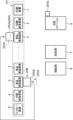
図8は、部品実装システム100の制御系を示すブロック図であり、主に、管理装置9と作業ロボット20の無人搬送車20Vの制御系を示している。
[Control system of component mounting system 100]
FIG. 8 is a block diagram showing a control system of
無人搬送車20Vは、その動作を統括的に制御する前記搬送車制御装置200を備えている。搬送車制御装置200には、記述の走行用センサ58、走行用モータ521及び電動シリンダ57等が電気的に接続されるとともに、送受信部210及びバッテリセンサ211が接続されている。送受信部210は、管理装置9との間で各種情報の通信を行うためのインターフェースであり、無線通信回線を通じて情報通信を行う。バッテリセンサ211は、バッテリの残量を検出するセンサである。The automated guided
搬送車制御装置200は、CPU,ROM、RAM及び周辺機器から構成されており、その機能構成として、走行制御部201、連結切替制御部202、バッテリ管理部203及びデータ記憶部204等を含む。The transport
走行制御部201は、走行用モータ521の駆動を制御することにより無人搬送車20Vの走行動作を制御する。走行制御部201は、送受信部210が管理装置9から取得する作業指令に基づき無人搬送車20Vを走行させる。主な作業指令は、フィーダ入替作業時に作業ロボット20(作業ユニット20U)を移動させる走行指令であるが、作業指令には、無人搬送車20V自体に充電を行わせるための充電指令なども含まれる。The driving
連結切替制御部202は、電動シリンダ57を制御することにより、作業ユニット20Uに対する無人搬送車20Vの連結及び連結解除を実行する。The connection
バッテリ管理部203は、バッテリセンサ211が検出するバッテリ残量を更新的に記録し、例えば一定期間毎に送受信部210を介してバッテリ残量データを管理装置9に送信する。The
データ記憶部204は、無人搬送車20Vの走行に必要な各種情報を記憶する。例えば、データ記憶部204には、生産ライン101、102の各装置1~5、補給部6、回収部7及び充電ステーション8各々の位置や走行ルートを含む地図情報が記憶されており、走行制御部201は、この地図情報に基づき無人搬送車20Vの走行を制御する。The
管理装置9は、管理制御装置300と、送受信部310とを備えている。送受信部310は、生産ライン101、102の各装置1~5及び無人搬送車20Vとの間で各種情報の通信を行うためのインターフェースである。The
管理制御部300は、生産ライン101、102の各装置1~5及び無人搬送車20Vから入力される情報に基づき、無人搬送車20V(作業ロボット20)に作業指令を送信する。当例では、部品実装装置3が部品補時期になると、管理制御部300は、無人搬送車20Vに作業指令を送信し、対象となる部品実装装置3の位置に作業ロボット20(作業ユニット20U)を移動させてフィーダ入替作業を実行させる。また、管理制御部300は、無人搬送車20Vから入力されるバッテリ残量データに基づき、バッテリ残量が所定レベル以下となっている場合には、当該無人搬送車20Vに対して充電指令を送信する。The
[作業ロボット20(無人搬送車20V)の動作]
次に、管理装置9(管理制御部300)の制御に基づく無人搬送車20Vの動作の一例について、図9~図14を参照しながら説明する。同図では、便宜上、一方の生産ライン(第1生産ライン101)のみ示している。
[Operation of working robot 20 (automated guided
Next, an example of the operation of the automated guided
部品実装装置3が部品補給時期になると、管理装置9から無人搬送車20Vに作業指令が送信される。すなわち、フィーダ入替作業のために作業ロボット20(作業ユニット20U)を移動させる旨の指令が無人搬送車20Vに送信される。When it is time for the
この作業指令の入力により、作業ロボット20は、所定の待機位置から先ず補給部6に移動し、交換用のテープフィーダ14を補給部6から受け取る。その後、作業ロボット20は、補給対象の部品実装装置3に向かって移動し、所定の作業位置においてフィーダ交換作業を開始する(図7参照)。
Upon input of this work command, the
図9は、2つの作業ロボット20(第1作業ロボット20A、第2作業ロボット20Bと称す)が各々異なる部品実装装置3に対してフィーダ入替作業を行っている状態を示している。2つの作業ロボット20A、20Bの構成は同じであり、互いに共通する連結機構55を備えている。
Figure 9 shows two work robots 20 (referred to as a
ここで、先に部品補給作業を開始した第1作業ロボット20Aの無人搬送車20V(第1無人搬送車20Vaと称す)のバッテリ残量が既定レベル以下となり、充電の時期が到来した場合を想定する。この場合には、管理装置9から第1無人搬送車20Vaに充電指令が送信される。充電指令を受けた第1無人搬送車20Vaは、作業ユニット20U(第1作業ユニット20Uaと称す)との連結状態を解除する。具体的には、電動シリンダ57を作動させて連結ヘッド56を下降させる(図5の実線に示す状態)。
Now, let us assume that the remaining battery charge of the automated guided
第1作業ユニット20Uaとの連結を解除すると、第1無人搬送車20Vaは自走して第1作業ユニット20Uaから離脱する。そして、図10に示すように、単独で充電ステーション8に移動し、充電を開始する。この場合、第1無人搬送車20Vaは、図外の受電端子を充電ステーション8の図外の給電端子に接触させることにより自ら充電を開始する。When the first automated guided vehicle 20Va is released from the first work unit 20Ua, it moves under its own power and separates from the first work unit 20Ua. Then, as shown in FIG. 10, it moves independently to the charging
第1無人搬送車20Vaが離脱した第1作業ユニット20Uaは、そのままフィーダ入替作業位置に残りフィーダ入替作業を継続する。記述の通り、第1作業ユニット20Uaは床面上に自立する構成であり、フィーダ入替作業位置に位置決めされた状態でクランプ機構37により部品実装装置3に固定されている。また、部品実装装置3から電力供給を受けている。そのため、フィーダ入替作業を支障無く継続することができる。
After the first automated guided vehicle 20Va has left, the first work unit 20Ua remains at the feeder replacement work position and continues the feeder replacement work. As described above, the first work unit 20Ua is configured to stand on its own on the floor surface, and is fixed to the
第1無人搬送車20Vaの充電が完了する前に第1作業ユニット20Ua(第1作業ロボット20A)によるフィーダ入替作業が完了し、かつ第2作業ロボット20Bがフィーダ入替作業中である場合には、管理装置9から第2作業ロボット20Bの無人搬送車20V(第2無人搬送車20Vbと称す)に対して第1作業ユニット20Uaを回収部7に移動させることを要求する指令が送信される。If the feeder replacement operation by the first work unit 20Ua (
この作業指令により、第2無人搬送車20Vbは、作業ユニット20U(第2作業ユニット20Ubと称す)との連結状態を解除し、自走することにより第2作業ユニット20Ubから離脱する。そして、図11に示すように、単独で第1作業ユニット20Uaの位置まで移動した後、この第1作業ユニット20Uaと連結し、図12に示すように、第1作業ユニット20Uaと共に回収部7に移動する。
In response to this work command, the second automated guided vehicle 20Vb releases its connection with the
第2無人搬送車20Vbが離脱した第2作業ユニット20Ubは、その間、そのままフィーダ入替作業位置に残りフィーダ入替作業を継続する。この場合も、第2作業ユニット20Ubは、部品実装装置3に対して位置決め固定され、かつ部品実装装置3から電力供給を受けているため、フィーダ入替作業を支障無く継続することができる。The second work unit 20Ub, from which the second automated guided vehicle 20Vb has left, remains at the feeder replacement work position and continues the feeder replacement work. In this case, too, the second work unit 20Ub is positioned and fixed relative to the
そして、回収されたテープフィーダ14が第1作業ユニット20Uaから回収部7に返却されている間に、第2作業ユニット20Ubによるフィーダ入替作業がすると、管理装置9から第2無人搬送車20Vbに、第2作業ユニット20Ubを回収部7に移動させることを要求する指令が送信される。この指令により、第2無人搬送車20Vbは、図13に示すように、第1作業ユニット20Uaとの連結状態を解除し、第1作業ユニット20Uaから離脱する。そして、元の第2作業ユニット20Ubの位置に移動して当該第2作業ユニット20Ubを連結した後、図14に示すように、当該第2作業ユニット20Ubと共に回収部7に移動する。
Then, when the second work unit 20Ub performs a feeder replacement operation while the collected
[作用効果]
この部品実装システム100で使用される作業ロボット20は、既述の通り、作業ユニット20Uと無人搬送車20Vとが連結状態と連結解除状態とに切替可能とされ、連結解除状態において、無人搬送車20Vは作業ユニット20Uから離脱して単独で走行することが許容される。また、作業ユニット20Uは、無人搬送車20Vが離脱した状態においても、フィーダ交換作業を継続可能に構成されている。そして、この部品実装システム100では、図9~図14を用いて説明したように、作業ロボット20(第2作業ロボット20A)によるフィーダ入替作業中に、必要に応じて、当該作業ロボット20の無人搬送車20V(第2無人搬送車20Vb)が他の作業ロボット20(第1作業ロボット20A)の作業ユニット20U(第1作業ユニット20Ua)の移動に使用される。そのため、作業ロボット20によるフィーダ入替作業中に無人搬送車20Vが遊んでしまうことが抑制され、無人搬送車20Vが有効に活用される。
[Action and Effect]
As described above, the working
また、この部品実装システム100によれば、記述のように、作業ロボット20(第1作業ロボット20A)によるフィーダ入替作業中に、当該作業ロボット20の無人搬送車20V(第2無人搬送車20Va)を充電ステーション8に移動させて充電を行う。そのため、作業ユニット20Uを有効に活用できるという利点もある。すなわち、作業ロボットにおいて作業ユニットと無人搬送車とが一体に構成されている、従来のような部品実装システムでは、充電ステーションに作業ロボットを移動させて充電を行う必要がある場合には、その間、作業ユニットに作業を行わせることができない。そのため、作業ユニットが遊んでしまう。しかし、上記部品実装システム100では、作業ユニット20Uによるフィーダ入替作業を継続しながら、無人搬送車20Vのみを充電ステーション8に移動させて充電を行うことができる。そのため、作業ユニット20Uを遊ばせることがなく、その分、作業ユニット20Uを有効に活用することができる。
In addition, according to this
なお、図9~図14に示した例では、2つの作業ロボット20(20A,20B)は各々が無人搬送車20V(20Va、20Vb)を備えており、一方側の作業ロボット20の無人搬送車20Vの充電時にのみ、他方側の作業ロボット20の無人搬送車20Vが前記一方側の作業ロボット20の作業ユニット20Uを移動させている。しかし、2つの作業ロボット20について1つの無人搬送車20Vを完全に共用させてもよい。つまりこの場合には、一方側の作業ロボット20を部品実装装置3の位置に移動させてフィーダ入替作業を開始した後、この作業ロボット20の作業ユニット20Uから無人搬送車20Vを離脱させる。そして、この無人搬送車20Vを他方側の作業ユニット20Uに連結して作業ロボット20を構築し、この作業ロボット20を他の部品実装装置3の位置に移動させてフィーダ入替作業を行わせる。
In the example shown in Figures 9 to 14, each of the two work robots 20 (20A, 20B) is equipped with an automatic guided
このような部品実装システム100の構成によれば、作業ユニット20Uの数に対して少ない数の無人搬送車20Vで部品実装装置3のフィーダ入替作業を行うことが可能となる。この場合、記述のように2つの作業ロボット20について1つの無人搬送車20Vを共用させる以外に、3つ以上の作業ロボット20について1乃至複数の無人搬送車20Vを共用させるようにしてもよい。
With such a configuration of the
また、前記作業ロボット20において、作業ユニット20Uは、床面上に自立した状態で、当該床面に沿って移動可能に構成されている。つまり、無人搬送車20Vが作業ユニット20Uからの荷重を受けない構成となっている。そのため、無人搬送車上に作業ユニットが一体に搭載されている従来の作業ロボットと比較すると、作業ロボット20を移動させるために必要な無人搬送車20Vの駆動力が抑えられる。つまり、低出力の走行用モータ521で作業ロボット20を走行させることが可能となり、無人搬送車20Vの低廉化や、省電力によるランニングコストの削減に寄与する。また、無人搬送車20Vに搭載されるバッテリを小型化することも可能であり、この場合には、無人搬送車20Vのバッテリ充電時間が短縮されるという利点もある。
In addition, in the working
また、作業ユニット20Uは、フィーダ入替作業を行う作業実行部40と、この作業実行部40の真下に配置されて当該作業実行部40を支持するユニットベース部30とを備えており、無人搬送車20Vは、ユニットベース部30に設けられた空洞状の搬送車収容部35に収容されて、当該ユニットベース部30に連結される。つまり、無人搬送車20Vは、作業ユニット20Uの真下に潜り込んだ状態で、当該作業ユニット20Uに連結される。従って、作業ユニットに対してその外周部分で無人搬送車が連結される構成と比べると、作業ロボット20の占有スペースが小さくなり(フットプリントが小さくなり)、走行スペースや作業スペースを縮小することが可能になるという利点がある。
The
また、無人搬送車20Vとユニットベース部30(作業ユニット20U)とを連結する連結機構55は、ユニットベース部30に対して作業ロボット20部が相対的に回転することを規制する回り止め機構を含む。そのため、作業ロボット20の移動時に作業ユニット20Uの走行方向が安定し易く、例えば、部品実装装置3に対して作業ユニット20Uを位置決めし易くなるといった利点もある。In addition, the
また、フィーダ入替作業中、作業ユニット20Uは、部品実装装置3から電力供給を受けるため、作業用電源としてバッテリを別途搭載する必要が無い。そのため、作業ユニット20Uや作業ロボット20の小型軽量化に寄与するという利点もある。
In addition, during the feeder replacement operation, the
また、フィーダ入替作業中、作業ユニット20Uはフィーダ入替作業位置に位置決めされた状態で、クランプ機構37により部品実装装置3に対して固定される。そのため、作業ユニット20Uから無人搬送車20Vが離脱した後も、作業ユニット20Uを確実にフィーダ入替作業位置に維持でき、当該作業ユニット20Uによるフィーダ入替作業を安定して継続させることができる。
During the feeder replacement operation, the working
[作業ロボット20の第2実施形態]
次に、作業ロボット20の第2実施形態について説明する。第2実施形態の作業ロボット20は、無人搬送車20Vと作業ユニット20Uとの連結構造が主に相違する。図15は、第2実施形態に係る作業ロボット20の要部側面図であり、連結前の作業ユニット20Uと無人搬送車20Vとを示している。
[Second embodiment of working robot 20]
Next, a second embodiment of the working
第2実施形態では、ユニットベース部30の搬送車収容部35内に上下に延びる連結軸38が備えられている。連結軸38は太軸部38bと細軸部38aとを上下に備えた段付き軸である。連結軸38は、その上端部がブラケット39を介してユニットベース部30の前側の側壁部34に固定されている。詳しくは、開口部35aに正対するように連結軸38が側壁部34に固定されている。In the second embodiment, a connecting
一方、無人搬送車20Vには、図16に示すような連結機構60が備えられている。図16は、連結機構60を示す平面図である。図15及び図16に示すように、連結機構60は、搬送車本体部50の前端部に設けられている。連結機構60は、ロック機構部62と回り止め機構部64とを含む。On the other hand, the automated guided
ロック機構部62は、無人搬送車20Vをユニットベース部30に対して固定する機構であり、連結軸38の細軸部38aに対応する高さ位置に配置されている。ロック機構部62は、ブロック状の固定ベース70と、この固定ベース70に揺動可能に支持される一対のレバー74と、このレバー74を開閉させるアーム77と、アーム77を駆動するモータ80とを備えている。The
ベース部70は、先端(図16では下側)に左右方向に延びる直方体形状のロック部70aと、その中央部から後方に延びる胴部70bとを備えた平面視T字型の形状を有している。ロック部70aの前端面中央には、後方に向かって凹む平面視台形状の凹部が形成されている。凹部72の内底部(後方端部)には、連結軸38の太軸部38bが嵌合可能な半円形状の嵌合部72aが設けられている。The
レバー74は、ロック部70aの前方であって凹部72の左右両側に各々配置されている。各レバー74は、ロック部70aの前面に沿って幅方向に延びる操作部74bと、操作部74bの一端から屈曲して凹部72の内側に向かって延びる先端部74aとを有する。各レバー74は、先端部74aと操作部74bとの境界部分においてピン75を介して床面に沿った方向に揺動可能に軸支されている。詳しくは、各レバー74の先端部74aが凹部72の内部で互いに近接したレバー閉位置と、凹部72の内部で各レバー74の先端部74aが互いに離間したレバー開位置とに揺動可能に軸支されている。各レバー74は、図外のばね部材の弾発力によりレバー閉位置に向かって付勢されている。The
アーム77は、ロック部70aの側面に沿って各々前後方向に延びる押圧部78aと、これら押圧部78aを連結する連結部78bを備えた平面視コ字型の形状を有している。アーム77は、ベース部70の胴部70bに設けられた図外のレール部に沿って前後方向にスライド可能に支持されている。連結部78bの中央部にはナット部78cが設けられており、前後方向に延びるねじ軸82がこのナット部78cに螺合、挿入されている。ねじ軸82の一端は、ベース部70(胴部70b)に固定されたモータ80の出力軸に連結されている。The
つまり、モータ80によりねじ軸82が回転駆動されるとアーム77が前進し、各押圧部78aにより各レバー74の操作部74bが前方に押圧される。この押圧により、各レバー74が前記ばね部材の弾発力に抗して各々レバー閉位置からレバー開位置に変位する(図17(b)参照)。そして、ねじ軸82が逆方向に回転駆動されると、アーム77が後退し、これに伴い、前記ばね部材の弾発力で各レバー74がレバー開位置からレバー閉位置に変位する。ロック機構部62は、これらレバー74とロック部70aとにより連結軸38(細軸部38a)を掴持することにより、無人搬送車20Vをユニットベース部30に固定する(すなわち、連結する)ように構成されている。That is, when the
回り止め機構部64は、ユニットベース部30に対して無人搬送車20Vが床面に沿った方向に回転ずれを起こすことを規制する機構である。この回り止め機構部64は、連結軸38の太軸部38bに対応する高さ位置に配置されている。The
図16では、便宜上、二点鎖線で図示しているが、回転止め機構部64は、ロック片84と、これを進退駆動する伝動シリンダ86とを備えている。連結軸38の太軸部38bには、ユニットベース部30の後方、すなわち開口部35aに向かって開口する嵌合凹部38cが形成されている。この嵌合凹部38cに太軸部38bが嵌入されることにより、ユニットベース部30に対する無人搬送車20Vの回転方向への変位が規制される。16, for convenience, the
次に、無人搬送車20Vとユニットベース部30との連結時及び連結解除時の連結機構60の動作について、図17を用いて説明する。図17は、連結機構60による連結状態と連結解除状態との切替え動作を説明する、当該連結機構60の平面図である。Next, the operation of the
無人搬送車20Vとユニットベース部30との連結時には、図15及び図16に示すように、連結機構60を先頭にして無人搬送車20Vが開口部35aから搬送車収容部35内に侵入し、連結軸38に向かって移動する。When the unmanned guided
無人搬送車20Vの移動に伴い、まず、各レバー74の先端部74aに連結軸38の細軸部38aが当接し、図17(a)の二点鎖線に示すように、ばね部材の弾発力に抗して各レバー74がレバー開位置に変位する。さらに無人搬送車20Vが前進すると、細軸部38aがベース部70(ロック部70a)の凹部72内に挿入されて嵌合部72aに嵌合すると共に、ばね部材の弾発力により各レバー74がレバー閉位置に変位する。これにより、図17(a)の実線に示すように、連結軸38(細軸部38a)がロック部70aとレバー74によって掴持される。そしてこの状態で、電動シリンダ86の作動によりロック片84が後退位置から前進位置に変位することにより、当該ロック片84が太軸部38bの嵌合凹部38cに嵌合する。これにより、図18に示すように、無人搬送車20Vがユニットベース部30に対して回り止めされた状態で、当該ユニットベース部30に対して連結される。As the automated guided
連結解除時には、まず、電動シリンダ86の作動によりロック片84が嵌合凹部38cから後退し、その後、モータ80の作動によりアーム77が後退位置から前進する。アーム77が前進すると、図17(b)に示すように、アーム77の各押圧部78aが各レバー74の操作部74bを前方に押圧し、ばね部材の弾発力に抗して各レバー74がレバー開位置に変位する。これによりロック部70aとレバー74とによる連結軸38の掴持状態が解除され、この状態で無人搬送車20Vが後退することにより、無人搬送車20Vとユニットベース部30との連結が解除される。When disconnecting, first, the
以上のような、第2実施形態の作業ロボット20の構成においても、第1実施形態の作業ロボット20と同様に、無人搬送車20Vと作業ユニット20Uとの連結及びその解除を行うことが可能であり、また、連結状態において、作業ユニット20Uに対する無人搬送車20Vの回転ずれを抑制することもできる。特に、この連結機構60によれば、連結機構60を先頭にして、開口部35aから連結軸38に向かってを無人搬送車20Vを前進させることで、比較的簡単に無人搬送車20Vとユニットベース部30(作業ユニット20U)とを連結させることができるという利点がある。As with the
[変形例]
以上説明した作業ロボット20及び部品実装システム100は、本発明に係る作業ロボット及び部品実装システムの好ましい実施形態の例示であって、それらの具体的な構成は、本発明の要旨を逸脱しない範囲で適宜変更可能である。例えば、以下の(1)~(3)のような構成も、本発明の範囲に属する。
[Modification]
The working
(1)実施形態では、本発明の「連結機構」として、図5及び図6(第1実施形態)や、図15~図18(第2実施形態)に示したような連結機構55,60が適用されている。しかし、「連結機構」は実施形態の連結機構55、60には限定されない。要は、無人搬送車20Vと共に作業ユニット20Uを移動させることが可能な連結状態と、作業ユニット20Uから離れて無人搬送車20Vが単独で走行することを許容する連結解除状態との切替えが可能な構成であればよい。但し、特に第1実施形態の連結機構55の構成によれば、構成が比較的簡単で、無人搬送車20Vへの搭載負担が少なく、また作業ユニット20U側の構造も簡素である。よって、低コストで簡単に実施できるとう利点がある。
(1) In the embodiment, the
(2)実施形態では、作業ロボット20(作業実行部40)が、部品供給エリア12との間でテープフィーダ14の入替作業を行う例について説明した。しかし、作業実行部40は、部品実装装置3に対してフィーダ入替作業以外の作業を行う構成であってもよい。例えば、部品をトレイ上に並べた状態で供給するトレイフィーダが部品供給エリア12に、(部品実装装置3)備えられる場合には、作業実行部40は、前記トレイや、複数のトレイが収容されたラックを部品実装装置3との間で入れ替える作業を行う構成であってもよい。また、テープフィーダ14が記述のようなカセット型以外の一般的なテープフィーダである場合には、作業実行部40は、補給部品として、テープが巻回されたリールを部品供給エリア12に受け渡す作業を行う構成でもよい。また、作業実行部40は、使用済みのテープを部品供給エリア12から回収する作業を行う構成であってもよい。
(2) In the embodiment, an example has been described in which the work robot 20 (the work execution unit 40) performs the work of replacing the
(3)実施形態では、作業ロボット20が、本発明の「部品実装基板を生産するための生産用装置」として部品実装装置3に対して作業を行う例について説明した。しかし、「生産用装置」は部品実装装置3以外の装置(印刷装置1等)であってもよい。また、実施形態では言及していないが、「生産用装置」は、印刷装置1に生産前の基板Pを送り込むローダ装置や、リフロー処理後の基板Pを回収するアンローダ装置であってもよい。この場合、作業実行部40は、ローダ装置に対して、例えば複数の基板Pが収容されたユニットの受け渡し作業を行い、また、アンローダ装置に対して、リフロー処理後の複数の基板Pが収容されたユニットを回収する作業を行うように構成される。また、「生産用装置」には、例えば準備Ar2に配置される、いわゆる自動倉庫も含まれる。この場合、作業実行部40は、自動倉庫で集荷された部品や機器を、当該自動倉庫との間で受け渡す作業を行うように構成される。
(3) In the embodiment, an example was described in which the working
以上説明した実施形態について本発明をまとめると以下の通りである。The present invention can be summarized as follows for the embodiments described above:
本発明の一局面に係る作業ロボットは、部品実装基板を生産するための生産用装置に対して所定作業を行う作業ユニットと、当該作業ユニットを搬送する無人搬送車と、を備えた作業ロボットであって、前記無人搬送車と共に前記作業ユニットを移動させることが可能な連結状態と、前記作業ユニットから離れて前記無人搬送車が単独で走行することを許容する連結解除状態との切替えが可能な連結機構を備え、前記作業ユニットは、前記生産用装置に対する前記所定作業の実行中に当該作業ユニットから前記無人搬送車が離れた状態でも、前記所定作業を継続可能に構成されていることを特徴とする。 A working robot according to one aspect of the present invention is a working robot comprising a work unit that performs a specified task on production equipment for producing component mounting boards, and an automated guided vehicle that transports the work unit, and is equipped with a coupling mechanism that can switch between a coupled state in which the work unit can be moved together with the automated guided vehicle, and a disconnected state in which the automated guided vehicle is allowed to move independently away from the work unit, and the work unit is configured to be able to continue the specified task even when the automated guided vehicle is separated from the work unit while the specified task is being performed on the production equipment.
この作業ロボットの構成によれば、生産用装置に対する前記所定作業の実行中に、作業ユニットと無人搬送車との連結状態を解除して、前記無人搬送車を他の用途に用いることが可能となる。そのため、無人搬送車が遊んでいる期間を低減することができ、無人搬送車をより有効に活用することができる。 With this configuration of the work robot, while the specified task is being performed on the production equipment, the connection between the work unit and the automated guided vehicle can be released, making it possible to use the automated guided vehicle for other purposes. This reduces the amount of time the automated guided vehicle is idle, allowing the automated guided vehicle to be used more effectively.
上記作業ロボットにおいて、前記作業ユニットは、前記無人搬送車が走行する床面上に自立した状態で当該床面に沿って移動可能に構成されているのが好適である。In the above-mentioned work robot, it is preferable that the work unit is configured to be movable along the floor surface on which the unmanned guided vehicle runs while standing independently on the floor surface.
この構成によれば、無人搬送車が作業ユニットからの荷重を受けないため、作業ロボットを移動させるために必要な無人搬送車の駆動力が抑えられる。そのため、より低出力の走行用モータで作業ロボットを移動させることが可能となり、無人搬送車の低廉化や、省電力によるランニングコストの削減に寄与する。 With this configuration, the AGV does not bear the load from the work unit, so the driving force required for the AGV to move the work robot is reduced. This makes it possible to move the work robot using a lower-output driving motor, contributing to lowering the cost of AGVs and reducing running costs by saving electricity.
より具体的な構成として、前記作業ユニットは、前記所定作業を実行する作業実行部と、この作業実行部の真下に配置され、前記作業実行部を前記床面に沿って移動可能に支持するユニットベース部とを備え、前記ユニットベース部は、前記無人搬送車が自走により出入り可能な空洞状の搬送車収容部を備え、前記連結機構は、前記搬送車収容部に収容された前記無人搬送車とユニットベース部とを連結するように構成されている。 More specifically, the work unit comprises a work execution section which executes the specified task, and a unit base section which is positioned directly below the work execution section and which supports the work execution section so that it can move along the floor surface, the unit base section comprises a hollow vehicle accommodation section which the unmanned guided vehicle can enter and exit by self-propelling, and the connecting mechanism is configured to connect the unmanned guided vehicle accommodated in the vehicle accommodation section to the unit base section.
この構成によれば、無人搬送車が作業ユニットの真下に潜り込んだ状態で、当該作業ユニットに連結されるため、作業ロボットの占有スペース化をより小さく抑えることが可能となる。 With this configuration, the automated guided vehicle is connected to the work unit while being positioned directly underneath it, making it possible to further reduce the space occupied by the work robot.
また、上記作業ロボットにおいて、前記連結機構は、前記連結状態において、前記ユニットベース部に対して前記無人搬送車が前記床面に沿った方向に回転することを規制する回り止め機構を含むのが好適である。 In addition, in the above-mentioned work robot, it is preferable that the connecting mechanism includes a rotation prevention mechanism that, in the connected state, restricts the automatic guided vehicle from rotating relative to the unit base portion in a direction along the floor surface.
この構成によれば、作業ロボットの移動時に作業ユニットの走行方向が安定し易くなり、生産用装置に対する位置決めが行い易くなる。 With this configuration, the running direction of the work unit becomes more stable when the work robot moves, making it easier to position it relative to the production equipment.
なお、前記生産用装置が、外部に電源供給が可能な給電コネクタを備えている場合には、前記作業ユニットは、前記生産用装置に対して前記所定作業を実行する所定の作業位置に配置された状態で、前記給電コネクタに嵌合可能な受電コネクタを備えているのが好適である。In addition, when the production device is equipped with a power supply connector capable of supplying power to the outside, it is preferable that the work unit is equipped with a power receiving connector that can be engaged with the power supply connector when placed in a predetermined work position where the specified work is performed on the production device.
この構成によれば、作業用電源としてバッテリを作業ユニットに搭載する必要が無くなる。そのため、作業ユニットや作業ロボットの小型軽量化に寄与する。 This configuration eliminates the need to install a battery in the work unit as a power source for the work, which contributes to making the work unit and work robot smaller and lighter.
一方、本発明の一局面に係る部品実装システムは、部品実装基板を生産するための生産用装置と、前記生産用装置に対して第1所定作業を行う第1作業ユニットを備えた請求項1乃至5の何れか一項に記載の作業ロボットと、前記生産用装置に対して第2所定作業を行う作業ユニットであって、前記作業ロボットの前記無人搬送車と共に請求項1乃至5の何れか一項の作業ロボットを構成可能な第2作業ユニットと、前記無人搬送車を制御する制御装置と、を備え、前記制御装置は、前記無人搬送車を走行させて前記作業ロボットを前記生産用装置の位置まで移動させた後、前記第1作業ユニットによる前記第1所定作業の実行中に、前記無人搬送車と前記第1作業ユニットとの連結状態を解除し、当該記無人搬送車を前記第2作業ユニットに連結させて当該第2作業ユニットを移動させる制御を実行する、ことを特徴とする。なお、第1所定作業と第2所定作業とは同一の作業であってもよいし、互いに異なる作業であってもよい。On the other hand, a component mounting system according to one aspect of the present invention includes a production device for producing component mounting boards, a work robot according to any one of claims 1 to 5, which is provided with a first work unit that performs a first predetermined work on the production device, a second work unit that performs a second predetermined work on the production device and is capable of constituting the work robot of any one of claims 1 to 5 together with the automatic guided vehicle of the work robot, and a control device that controls the automatic guided vehicle, and the control device performs control to release the automatic guided vehicle from the first work unit during the execution of the first predetermined work by the first work unit, and to couple the automatic guided vehicle to the second work unit to move the second work unit. The first predetermined work and the second predetermined work may be the same work or different works.
この部品実装システムの構成によれば、第1作業ユニットによる第1所定作業の実行中の期間を利用して、無人搬送車に第2作業ユニットを移動させることができる。そのため、無人搬送車が遊んでいる期間を低減でき、無人搬送車を有効活用することが可能となる。 This component mounting system configuration allows the second work unit to be moved to the automated guided vehicle by utilizing the period during which the first work unit is performing the first specified task. This reduces the period during which the automated guided vehicle is idle, enabling the automated guided vehicle to be used more effectively.
なお、上記の部品実装システムにおいて、前記生産用装置又は前記第1作業ユニットには、前記生産用装置に対して前記第1所定作業を実行する所定の作業位置に前記第1作業ユニットが配置された状態で、当該第1作業ユニットと前記生産装置とを固定するクランプ機構が備えられているのが好適である。In addition, in the above-mentioned component mounting system, it is preferable that the production device or the first work unit is provided with a clamping mechanism that fixes the first work unit and the production device when the first work unit is positioned at a predetermined work position where the first specified work is performed on the production device.
この構成によれば、第1作業ユニットから無人搬送車が離脱した状態でも、所定の作業位置に第1作業ユニットを配置させて状態で、安定的に第1所定作業を継続させることが可能となる。 With this configuration, even when the automated guided vehicle has detached from the first work unit, it is possible to stably continue the first specified work with the first work unit positioned at the specified work position.
Claims (10)
前記無人搬送車と共に前記作業ユニットを移動させることが可能な連結状態と、前記作業ユニットから離れて前記無人搬送車が単独で走行することを許容する連結解除状態との切替えが可能な連結機構を備え、
前記作業ユニットは、前記生産用装置に対する前記所定作業の実行中に当該作業ユニットから前記無人搬送車が離れた状態でも、前記所定作業を継続可能に構成され、
前記生産用装置は、複数のフィーダが配置された部品供給エリアを備え、前記フィーダが供給する部品を基板に実装する部品実装装置であり、
前記作業ユニットは、前記所定作業として、前記部品供給エリアに対して、前記フィーダの供給作業及び/又は回収作業を一フィーダ毎に行う、ことを特徴とする作業ロボット。 A working robot including a work unit that performs a predetermined operation on a production device for producing component-mounted boards, and an automated guided vehicle that transports the work unit,
a coupling mechanism that can be switched between a coupled state in which the working unit can be moved together with the automated guided vehicle and a disconnected state in which the automated guided vehicle is allowed to travel independently away from the working unit,
the operational unit is configured to be able to continue the predetermined task even when the automated guided vehicle is separated from the operational unit during the execution of the predetermined task on the production device ,
the production device is a component mounting device that includes a component supply area in which a plurality of feeders are arranged and that mounts components supplied by the feeders onto a board;
The working robot, wherein the work unit performs, as the predetermined task, a supply task and/or a collection task for the feeders in the part supply area, one feeder at a time .
前記作業ユニットは、前記無人搬送車が走行する床面上に自立した状態で当該床面に沿って移動可能に構成されている、ことを特徴とする作業ロボット。 2. The working robot according to claim 1,
A working robot characterized in that the working unit is configured to be movable along a floor surface on which the automatic guided vehicle travels while being independent of the floor surface.
前記作業ユニットは、前記所定作業を実行する作業実行部と、この作業実行部の真下に配置され、前記作業実行部を前記床面に沿って移動可能に支持するユニットベース部とを備え、
前記ユニットベース部は、前記無人搬送車が自走により出入り可能な空洞状の搬送車収容部を備え、
前記連結機構は、前記搬送車収容部に収容された前記無人搬送車とユニットベース部とを連結するように構成されている、ことを特徴とする作業ロボット。 The working robot according to claim 2,
the work unit includes a work execution section that executes the predetermined work, and a unit base section that is disposed directly below the work execution section and supports the work execution section so that the work execution section can move along the floor surface;
the unit base portion includes a hollow vehicle accommodation portion into which the automated guided vehicle can enter and exit by self-propelling,
A working robot, characterized in that the connecting mechanism is configured to connect the unmanned guided vehicle accommodated in the guided vehicle accommodation section to a unit base section.
前記連結機構は、前記連結状態において、前記ユニットベース部に対して前記無人搬送車が前記床面に沿った方向に回転することを規制する回り止め機構を含む、ことを特徴とする作業ロボット。 The working robot according to claim 3 ,
A working robot according to claim 1, wherein the connecting mechanism includes a rotation prevention mechanism that, in the connected state, restricts the automatic guided vehicle from rotating relative to the unit base portion in a direction along the floor surface.
前記生産用装置は、外部に電源供給が可能な給電コネクタを備えており、
前記作業ユニットは、前記生産用装置に対して前記所定作業を実行する所定の作業位置に配置された状態で、前記給電コネクタに嵌合可能な受電コネクタを備えている、ことを特徴とする作業ロボット。 The working robot according to any one of claims 1 to 4,
The production device includes a power supply connector capable of supplying power to an external device,
The working robot is characterized in that the working unit is provided with a power receiving connector that can be fitted to the power supply connector when the working unit is placed at a predetermined working position where the predetermined work is performed on the production device.
前記生産用装置に対して第1所定作業を行う第1作業ユニットを備えた請求項1乃至5の何れか一項に記載の作業ロボットと、
前記生産用装置に対して第2所定作業を行う作業ユニットであって、前記作業ロボットの前記無人搬送車と共に請求項1乃至5の何れか一項の作業ロボットを構成可能な第2作業ユニットと、
前記無人搬送車を制御する制御装置と、を備え、
前記制御装置は、前記無人搬送車を走行させて前記作業ロボットを前記生産用装置の位置まで移動させた後、前記第1作業ユニットによる前記第1所定作業の実行中に、前記無人搬送車と前記第1作業ユニットとの連結状態を解除し、当該無人搬送車を前記第2作業ユニットに連結させて当該第2作業ユニットを移動させる制御を実行する、ことを特徴とする部品実装システム。 A production device for producing component-mounted boards;
The working robot according to any one of claims 1 to 5 , further comprising a first working unit configured to perform a first predetermined task on the production device;
a second work unit that performs a second predetermined work on the production device, the second work unit being capable of constituting the work robot according to any one of claims 1 to 5 together with the automatic guided vehicle of the work robot;
A control device for controlling the automated guided vehicle,
The control device controls the automated guided vehicle to move the work robot to the position of the production equipment, and then, while the first work unit is performing the first specified task, releases the connection between the automated guided vehicle and the first work unit, and couples the automated guided vehicle to the second work unit to move the second work unit.
前記生産用装置又は前記第1作業ユニットには、前記生産用装置に対して前記第1所定作業を実行する所定の作業位置に前記第1作業ユニットが配置された状態で、当該第1作業ユニットと前記生産用装置とを固定するクランプ機構が備えられている、ことを特徴とする部品実装システム。 7. The component mounting system according to claim 6 ,
a clamping mechanism for fixing the first work unit and the production device when the first work unit is positioned at a predetermined work position for performing the first specified work on the production device, the clamping mechanism being provided on the production device or the first work unit.
前記生産用装置に対して所定作業を行う作業ユニットを備えた請求項1乃至5の何れか一項に記載の作業ロボットと、
前記作業ロボットの前記無人搬送車の充電設備である充電ステーションと、
前記無人搬送車を制御する制御装置と、を備え、
前記制御装置は、前記無人搬送車を走行させて前記作業ロボットを前記生産用装置の位置まで移動させた後、前記作業ユニットによる前記所定作業の実行中に、前記無人搬送車と前記作業ユニットとの連結状態を解除し、当該無人搬送車を充電ステーションに移動させて当該無人搬送車に充電を行わせる制御を実行する、ことを特徴とする部品実装システム。 A plurality of production devices for producing component-mounted boards;
The working robot according to any one of claims 1 to 5 , further comprising a working unit that performs a predetermined task on the production device;
A charging station which is a charging facility for the automatic guided vehicle of the working robot;
A control device for controlling the automated guided vehicle,
The component mounting system is characterized in that the control device drives the automated guided vehicle to move the work robot to the position of the production equipment, and then, while the work unit is performing the specified task, controls the automated guided vehicle to release the connection between the automated guided vehicle and the work unit, move the automated guided vehicle to a charging station, and charge the automated guided vehicle.
前記無人搬送車は、バッテリの残量データを前記制御装置に送信するバッテリ管理部を備え、
前記制御装置は、前記残量データに基づき、バッテリ残量が所定レベル以下となっている場合に、前記無人搬送車に充電を行わせる制御を実行する、ことを特徴とする部品実装システム。 9. The component mounting system according to claim 8 ,
the automated guided vehicle includes a battery management unit that transmits remaining battery charge data to the control device;
The component mounting system is characterized in that the control device executes control to cause the automated guided vehicle to charge when the battery remaining charge is below a predetermined level based on the remaining charge data.
前記所定作業を第1所定作業、前記作業ユニットを第1作業ユニット、前記無人搬送車を第1無人搬送車と定義したとき、
前記生産用装置に対して第2所定作業を行う第2作業ユニット及び第2無人搬送車を備えた請求項1乃至5の何れか一項に記載の第2作業ロボットをさらに含み、
前記制御装置は、前記第1無人搬送車に充電を行わせる制御の実行中に、前記第2所定作業を行っている前記第2作業ユニットと前記第2無人搬送車との連結状態を解除し、当該第2無人搬送車を前記第1作業ユニットに連結させて当該第1作業ユニットを移動させる制御を実行する、ことを特徴とする部品実装システム。 10. The component mounting system according to claim 8 ,
When the predetermined task is defined as a first predetermined task, the work unit is defined as a first work unit, and the automated guided vehicle is defined as a first automated guided vehicle,
The second work robot according to any one of claims 1 to 5 , further comprising a second work unit and a second automated guided vehicle that perform a second predetermined task on the production device,
The control device, while executing control to charge the first unmanned guided vehicle, executes control to disconnect the second work unit performing the second specified task from the second unmanned guided vehicle, and to connect the second unmanned guided vehicle to the first work unit to move the first work unit.
Applications Claiming Priority (1)
| Application Number | Priority Date | Filing Date | Title |
|---|---|---|---|
| PCT/JP2021/044147 WO2023100298A1 (en) | 2021-12-01 | 2021-12-01 | Work robot and component mounting system |
Publications (3)
| Publication Number | Publication Date |
|---|---|
| JPWO2023100298A1 JPWO2023100298A1 (en) | 2023-06-08 |
| JPWO2023100298A5 JPWO2023100298A5 (en) | 2024-08-22 |
| JP7620122B2 true JP7620122B2 (en) | 2025-01-22 |
Family
ID=86611798
Family Applications (1)
| Application Number | Title | Priority Date | Filing Date |
|---|---|---|---|
| JP2023564346A Active JP7620122B2 (en) | 2021-12-01 | 2021-12-01 | Working robot and component mounting system |
Country Status (4)
| Country | Link |
|---|---|
| JP (1) | JP7620122B2 (en) |
| CN (1) | CN118318512A (en) |
| DE (1) | DE112021008309T5 (en) |
| WO (1) | WO2023100298A1 (en) |
Families Citing this family (3)
| Publication number | Priority date | Publication date | Assignee | Title |
|---|---|---|---|---|
| WO2025109650A1 (en) * | 2023-11-20 | 2025-05-30 | ヤマハ発動機株式会社 | Work device, device on which to perform work, work system, and method for adjusting position of work unit relative to device on which to perform work |
| WO2025109651A1 (en) * | 2023-11-20 | 2025-05-30 | ヤマハ発動機株式会社 | Work device, work target device, work system, and method for adjusting position of working part with respect to work target device |
| WO2025253971A1 (en) * | 2024-06-07 | 2025-12-11 | パナソニックIpマネジメント株式会社 | Conveyance system, conveyance device, attachment, grippable part, gripping part, component mounting system, and control method |
Citations (3)
| Publication number | Priority date | Publication date | Assignee | Title |
|---|---|---|---|---|
| JP2010212409A (en) | 2009-03-10 | 2010-09-24 | Panasonic Corp | Method of mounting component |
| JP2015015368A (en) | 2013-07-05 | 2015-01-22 | Juki株式会社 | Component exchange carriage, electronic component-mounting device, and electronic component supply device |
| JP2020047801A (en) | 2018-09-20 | 2020-03-26 | パナソニックIpマネジメント株式会社 | Feeder carriage |
Family Cites Families (3)
| Publication number | Priority date | Publication date | Assignee | Title |
|---|---|---|---|---|
| JP2792956B2 (en) * | 1989-11-10 | 1998-09-03 | 三洋電機株式会社 | Parts supply system |
| JPH05265551A (en) * | 1992-03-23 | 1993-10-15 | Suzuki Motor Corp | Carrying device |
| JP6074425B2 (en) | 2012-07-13 | 2017-02-01 | 富士機械製造株式会社 | Component mounting system |
-
2021
- 2021-12-01 CN CN202180103761.8A patent/CN118318512A/en active Pending
- 2021-12-01 JP JP2023564346A patent/JP7620122B2/en active Active
- 2021-12-01 DE DE112021008309.0T patent/DE112021008309T5/en active Pending
- 2021-12-01 WO PCT/JP2021/044147 patent/WO2023100298A1/en not_active Ceased
Patent Citations (3)
| Publication number | Priority date | Publication date | Assignee | Title |
|---|---|---|---|---|
| JP2010212409A (en) | 2009-03-10 | 2010-09-24 | Panasonic Corp | Method of mounting component |
| JP2015015368A (en) | 2013-07-05 | 2015-01-22 | Juki株式会社 | Component exchange carriage, electronic component-mounting device, and electronic component supply device |
| JP2020047801A (en) | 2018-09-20 | 2020-03-26 | パナソニックIpマネジメント株式会社 | Feeder carriage |
Also Published As
| Publication number | Publication date |
|---|---|
| DE112021008309T5 (en) | 2024-08-14 |
| CN118318512A (en) | 2024-07-09 |
| JPWO2023100298A1 (en) | 2023-06-08 |
| WO2023100298A1 (en) | 2023-06-08 |
Similar Documents
| Publication | Publication Date | Title |
|---|---|---|
| JP7620122B2 (en) | Working robot and component mounting system | |
| US6266873B1 (en) | Method and apparatus for mounting electronic components | |
| US11765876B2 (en) | Exchange device | |
| JP7531157B2 (en) | Material Handling System | |
| JP7518979B2 (en) | Transport robots and component mounting systems | |
| KR102820827B1 (en) | Transfer system | |
| JP7422223B2 (en) | Board manufacturing system, autonomous vehicle and board manufacturing method | |
| JP7656079B2 (en) | Transport robot and component mounting system | |
| JP7531156B2 (en) | Item transport device | |
| WO2024095326A1 (en) | Transfer device | |
| JP7519607B2 (en) | Material Handling System | |
| WO2022224432A1 (en) | Mounting system | |
| JP6974609B2 (en) | Exchange device | |
| JP7394308B2 (en) | Parts mounting device | |
| EP4369880A1 (en) | Battery feeder | |
| JP7229405B2 (en) | Component placement system | |
| JP7715742B2 (en) | Mounting System | |
| JP7372490B2 (en) | Parts mounting system | |
| JP2021077792A (en) | Component mounting machine | |
| CN120035115A (en) | Feeder replacement | |
| WO2022145317A1 (en) | Article conveyor | |
| JP2022118203A (en) | Component type management device | |
| WO2025238851A1 (en) | Component-mounting system |
Legal Events
| Date | Code | Title | Description |
|---|---|---|---|
| A529 | Written submission of copy of amendment under article 34 pct |
Free format text: JAPANESE INTERMEDIATE CODE: A5211 Effective date: 20240501 |
|
| A621 | Written request for application examination |
Free format text: JAPANESE INTERMEDIATE CODE: A621 Effective date: 20240501 |
|
| A521 | Request for written amendment filed |
Free format text: JAPANESE INTERMEDIATE CODE: A523 Effective date: 20240805 |
|
| A131 | Notification of reasons for refusal |
Free format text: JAPANESE INTERMEDIATE CODE: A131 Effective date: 20241119 |
|
| A521 | Request for written amendment filed |
Free format text: JAPANESE INTERMEDIATE CODE: A523 Effective date: 20241219 |
|
| TRDD | Decision of grant or rejection written | ||
| A01 | Written decision to grant a patent or to grant a registration (utility model) |
Free format text: JAPANESE INTERMEDIATE CODE: A01 Effective date: 20250107 |
|
| A61 | First payment of annual fees (during grant procedure) |
Free format text: JAPANESE INTERMEDIATE CODE: A61 Effective date: 20250109 |
|
| R150 | Certificate of patent or registration of utility model |
Ref document number: 7620122 Country of ref document: JP Free format text: JAPANESE INTERMEDIATE CODE: R150 |