EP4380738B1 - Vorrichtung zum durchsetzfügen - Google Patents
Vorrichtung zum durchsetzfügen Download PDFInfo
- Publication number
- EP4380738B1 EP4380738B1 EP22761060.7A EP22761060A EP4380738B1 EP 4380738 B1 EP4380738 B1 EP 4380738B1 EP 22761060 A EP22761060 A EP 22761060A EP 4380738 B1 EP4380738 B1 EP 4380738B1
- Authority
- EP
- European Patent Office
- Prior art keywords
- movement
- joining
- control device
- component
- unit
- Prior art date
- Legal status (The legal status is an assumption and is not a legal conclusion. Google has not performed a legal analysis and makes no representation as to the accuracy of the status listed.)
- Active
Links
Images
Classifications
-
- B—PERFORMING OPERATIONS; TRANSPORTING
- B21—MECHANICAL METAL-WORKING WITHOUT ESSENTIALLY REMOVING MATERIAL; PUNCHING METAL
- B21D—WORKING OR PROCESSING OF SHEET METAL OR METAL TUBES, RODS OR PROFILES WITHOUT ESSENTIALLY REMOVING MATERIAL; PUNCHING METAL
- B21D39/00—Application of procedures in order to connect objects or parts, e.g. coating with sheet metal otherwise than by plating; Tube expanders
- B21D39/03—Application of procedures in order to connect objects or parts, e.g. coating with sheet metal otherwise than by plating; Tube expanders of sheet metal otherwise than by folding
- B21D39/031—Joining superposed plates by locally deforming without slitting or piercing
-
- B—PERFORMING OPERATIONS; TRANSPORTING
- B21—MECHANICAL METAL-WORKING WITHOUT ESSENTIALLY REMOVING MATERIAL; PUNCHING METAL
- B21J—FORGING; HAMMERING; PRESSING METAL; RIVETING; FORGE FURNACES
- B21J15/00—Riveting
- B21J15/02—Riveting procedures
- B21J15/025—Setting self-piercing rivets
-
- B—PERFORMING OPERATIONS; TRANSPORTING
- B21—MECHANICAL METAL-WORKING WITHOUT ESSENTIALLY REMOVING MATERIAL; PUNCHING METAL
- B21J—FORGING; HAMMERING; PRESSING METAL; RIVETING; FORGE FURNACES
- B21J15/00—Riveting
- B21J15/10—Riveting machines
- B21J15/28—Control devices specially adapted to riveting machines not restricted to one of the preceding subgroups
-
- B—PERFORMING OPERATIONS; TRANSPORTING
- B21—MECHANICAL METAL-WORKING WITHOUT ESSENTIALLY REMOVING MATERIAL; PUNCHING METAL
- B21J—FORGING; HAMMERING; PRESSING METAL; RIVETING; FORGE FURNACES
- B21J15/00—Riveting
- B21J15/10—Riveting machines
- B21J15/30—Particular elements, e.g. supports; Suspension equipment specially adapted for portable riveters
-
- B—PERFORMING OPERATIONS; TRANSPORTING
- B23—MACHINE TOOLS; METAL-WORKING NOT OTHERWISE PROVIDED FOR
- B23P—METAL-WORKING NOT OTHERWISE PROVIDED FOR; COMBINED OPERATIONS; UNIVERSAL MACHINE TOOLS
- B23P19/00—Machines for simply fitting together or separating metal parts or objects, or metal and non-metal parts, whether or not involving some deformation; Tools or devices therefor so far as not provided for in other classes
- B23P19/04—Machines for simply fitting together or separating metal parts or objects, or metal and non-metal parts, whether or not involving some deformation; Tools or devices therefor so far as not provided for in other classes for assembling or disassembling parts
- B23P19/06—Screw or nut setting or loosening machines
- B23P19/062—Pierce nut setting machines
Definitions
- Functional elements are preferably understood to be press-in elements which, when set on the workpiece, have an additional function to the outside, for example a connecting or fastening section, such as an external thread for connecting the connecting or fastening section to another section.
- a connecting or fastening section such as an external thread for connecting the connecting or fastening section to another section.
- the object of the present invention is to improve the devices and joining tongs described in the introduction.
- the aim is to easily resolve clearance problems in such devices.
- disadvantages due to frequently occurring critical cycle times are to be minimized.
- Critical cycle times are characterized in particular by a comparatively long immersion or approach time of the joining tongs toward the component and/or a comparatively long clearance time of the joining tongs away from the component.
- the invention is based on a device for clinching a component or for setting a joining element or a functional element on a component, comprising a holding section with which the device can be positioned on a receptacle in the environment, and a base body which is mounted on the holding section via a bearing point, and wherein a die unit with a die element and a stamp unit with a stamp opposite the die unit are received on the base body, wherein a drive unit is provided for moving the stamp and/or the die element, which drive unit reversibly drives a linearly movable actuating element coupled to the stamp or the die element along a joining axis of the device in order to act on the component present between the stamp unit and the die unit.
- joining pliers is used instead of the term “device” in an equivalent manner and, in particular, is not restricted to joining.
- the core of the invention lies in the fact that the base body is movable relative to the holding section via the bearing point, and wherein a control device is configured between the actuating element and the holding section such that, depending on the position of the actuating element along the joining axis, the position of the base body relative to the holding section is predetermined due to the driven movement of the actuating element.
- the control device forms a mechanical coupling via which the actuating element, for example, a working piston of a drive unit with a piston-cylinder unit, is preferably permanently connected to the holding section, such as a holding or machine frame.
- the control device can provide a motion coupling between the driven linear movement of the actuating element and the movement of the base body relative to the holding section.
- the linear movement of the actuating element preferably occurs relative to a fixed section on which the actuating element is movably mounted.
- the fixed section is, for example, a housing surrounding the actuating element with a rolling bearing device between the housing and the actuating element.
- a compensating movement for example of a section of the device or the base body that is connected to the punch side and/or the die side, can be carried out simultaneously with the working stroke of the device or the joining tongs.
- the compensating movement is carried out by the driven movement of the punch and/or by the driven movement of the die element.
- the compensating movement is, in particular, a movement that is connected to the drive movement. Forced-coupled movement.
- the drive unit moves along with the base body.
- the proposed device for clinching or for setting functional elements or joining elements meets the requirement of enabling an optimized movement of the base body, which in particular includes a compensating movement.
- the entire device is moved free from the component simultaneously with the punch unit moving away from the component and/or the die unit moving away from the component.
- the holding section or the holding or machine frame is preferably an integral part of an overall machine, such as the entire device.
- the device according to the invention can be used to meet frequently occurring requirements, even in combination, for example, the single immersion of the joining tongs into a component and/or in or on the component. Also, the execution of several joining operations with a comparatively short retraction stroke between individual processing steps and/or the extension or removal of the joining tongs from the component and/or a transfer operation to the The next component can advantageously be achieved in combination.
- the invention preferably allows a defined movement of the device or joining tongs relative to the component during the joining process. This is particularly advantageous or necessary when the joining direction is inverted by exchanging the punch unit and die unit as far as the drive is concerned. It is preferred or necessary that the component remains spatially motionless during the joining process. For this purpose, it is preferably the case that during the joining process the joining tongs are moved in a synchronized manner in the opposite direction to the distance that the punch or rivet, the functional element or the joining element penetrates into the component. The opposite movement is synchronized in particular in direction and/or amount.
- the holding section can be fixed, for example, attached to a section of a building.
- the holding section can be movable, for example, on a robot arm.
- the component for example, a plate-like workpiece, can be single-layered or multi-layered, or consist of several layers of material.
- the actuating element is preferably a linear motion element, such as a part of a piston-cylinder drive, such as a working piston of the device or the joining tongs.
- the drive unit is optionally a hydropneumatic, pneumatic, hydraulic, and/or electric drive unit.
- the electric drive unit preferably comprises an electric motor, preferably an electric spindle drive.
- the control device comprises a guide track and a guide member movable along the guide track, preferably a guide member displaceably movable along the guide track.
- the guide track can provide a guide curve for the curved guide member.
- the preferably curved or track-guiding control device couples the driven movement of the actuating element or the punch or die element to the holding section. This preferably predetermines the movement or position, in particular of the base body, relative to the holding section, depending on the movement of the actuating element. This allows a compensating movement of the base body to be set up, in particular depending on the travel distance traveled by the punch or die element and thus depending on the distance between a driven, movable free end of the punch and/or die element and the component.
- a compensating movement predetermined by the movement of the base body for example a Pivoting movement of the base body around its bearing point on the holding section, and thus of the punch and/or die unit, can advantageously be predetermined before and/or after the actual deformation of the component.
- the compensating movement is particularly coordinated with the driven movement of the punch and/or die element.
- a movement path and a movement position of the base body can preferably be set up in a precisely spatially and temporally repeatable manner and, in particular, can be aligned with a drive movement. The alignment preferably takes place in both opposite directions along the guideway. It is also possible for the control device to be designed such that during the movement of the actuating element, i.e.
- the guideway is formed on the holding section.
- the holding section can be one-, two-, or multi-part, preferably one-part.
- a section of the holding section facing the drive unit with the actuating element can have the guideway.
- the section of the holding section with the guideway is, for example, facing away from a section of the holding section that is fixed to a fixed device or, for example, a spatially movable robot arm.
- the guideway is suitably matched, for example as a particularly elongated single or double or multiple curved track, so that a guide element matched to the guideway, for example a pin, a roller or a bolt, is continuously guided in the guideway, sliding smoothly or moving evenly and without jerking.
- a guide element matched to the guideway for example a pin, a roller or a bolt
- the control device comprises a slotted guide.
- the slotted guide preferably comprises a slotted control with a gear element.
- the slotted guide comprising, for example, a guide track on the holding section and a gear element guided and movable along the guide track, is easy to provide, space-saving, stable, and advantageous for reliably guided movement.
- the track-guided gear element is preferably a guide member on the actuating element.
- a guide track is preferably a recess, for example in the manner of an elongated hole, straight and/or curved and/or with an angled profile, e.g., in a thin, flat material such as a sheet metal section.
- Corresponding aligned sections of the guide track are preferably formed in two opposite, preferably parallel, sheet metal sections, in particular in exactly two sheet metal sections that are spaced apart in the direction of a normal to a sheet metal section and have a free intermediate region between them.
- the guideway is, at least in sections, discontinuously and/or continuously curved.
- the guideway for example the link guideway, is adjusted in such a way that a movement of the base body or a movement of the punch and/or die unit or a die element of the die unit relative to the component during the joining or setting process is avoided or almost avoided.
- control device is designed according to the toggle lever principle. This allows lever forces and moments to be advantageously provided.
- the movement coupling that can be provided with the control device is between the driven linear movement of the actuating element and the movement of the base body relative to the holding section according to the principle of toggle lever coupling.
- control device comprises a guide member connected to the actuating element.
- the guide member is preferably firmly and preferably rigidly connected to the actuating element.
- the guide member which is preferably spherical or convex on the outside, such as a pin, a roller, a pinion, a friction wheel or a bolt, runs along a guide track, such as the track of a slotted guide.
- the guide track has, for example, flat or contoured sections, such as tooth profile-shaped sections, which come into operative contact with the outside of the guide member.
- the guide member is linearly movable with the drive unit or moves in a fixedly coupled manner with the actuating element.
- the bearing point comprises a pivot bearing.
- a pivot bearing is easy to install, space-saving, and stable.
- the axis of rotation formed with the pivot bearing is preferably perpendicular to the joining axis or perpendicular to the direction of movement of the linearly movable actuating element.
- the pivot bearing comprises, for example, an elongated bearing pin which, for example, releasably engages through openings in the base body and/or holding section, or engages through, for example, a bearing opening matching the bearing pin or preferably through two or more spaced-apart matching bearing openings.
- the at least one bearing opening is preferably provided in the holding section.
- the pivot bearing is preferably designed as a plain bearing or as a rolling element bearing.
- the pivot bearing comprises, as a bearing pin, a screw which can be axially pushed through and axially secured through aligned openings, for example with a screwable nut.
- the bearing point comprises an axial bearing.
- the bearing point between the holding section, such as a holding or machine frame, and the base body, such as the counterforce frame, is preferably an axial bearing comprising, for example, a linearly movable carriage.
- a linear movement for example, oblique to a spatially fixed axis, can be specified at the bearing point of the base body on the holding section.
- An axial bearing is also referred to as a longitudinal bearing, thrust bearing, or track bearing.
- a relief device for mechanically relieving the load on the control device. This reduces forces and/or moments acting on or on the components of the control device, such as a guide track and/or on the guide member movable along the guide track, to a non-critical level, so that only tolerable friction effects and/or no permanent or plastic deformation of parts of the control device occur.
- the relief preferably comprises an additional element, which counteracts, in particular, the effects of gravity.
- an element provides forces and/or moments and comprises, for example, a spring or a pneumatic device with a pneumatic cylinder and a pneumatic piston and/or a hydraulic device. Due to the convex shape, the guide element can be formed in a simple and stable manner. Furthermore, the guide element is advantageously designed with regard to frictional influences between the guide element and sections of the guideway. Tilting, jerking or blocking of the guide element in the guideway during movement in the guideway can be advantageously minimized or avoided.
- the guide element is preferably spherical on the outside, for example, circular, elliptical, or cylindrical in cross-section.
- the guide element is designed, for example, as a roller, cylinder, bolt, or pin.
- the control device is advantageously designed such that the position of the base body relative to the holding section remains unchanged during a clinching process or during a setting process. Accordingly, this is generally only the case in phases or not for the entire time the driven punch or actuating element is moving. This allows for the desired operational control to be optimized. In particular, phases in which the base body remains stationary are also possible during the driven movement of the punch or die element, for example, to continuously fix and/or support the component.
- control device is designed such that, during a clinching process or during a setting process, the direction and amount of movement of the die unit are opposite to the direction and amount of movement of the punch. This applies, for example, if the die unit is located on the active side of the drive unit or the working piston, or if the drive is provided or driven on the die unit side. The die unit is then located on the side of the actuating element, or the actuating element is connected to the driven die part.
- the time-distance movement profile of the die unit during the joining or setting process corresponds at least almost to the opposite movement profile of the punch. This ensures, for example, that the component is Holding section or to the machine frame and to the base body or to the counterforce frame remains at least almost at rest.
- the device is designed as a joining tong with a C-frame.
- This also applies to all other devices of the invention.
- This arrangement is a proven design.
- the C-frame joining tong can be wall-mounted, for example, or attached to a robot arm and spatially movable.
- the C-frame forms at least essentially the base body.
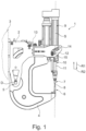
- Fig. 1 shows a fully retracted or closed device 1 for clinching a component B or for placing a joining, functional, or connecting element on the component B.
- the device 1 is designed, for example, as a joining, clinching, or punching tool.
- the device 1 with a joining axis S is designed as a clinching tool or a tool for clinching or clinching.
- the device 1 comprises a holding section 2, with which the device 1 can be positioned on a receptacle 3 (indicated by dashed lines), such as a robot arm or a wall in the surrounding area.
- the holding section 2 serves as a holding frame or machine frame.
- the device 1 has a base body 4, which is mounted on the holding section 2 via a bearing point 5.
- the bearing point 5 is designed such that the base body 4 has at least one open spatial degree of freedom.
- the bearing point 5 here is, for example, a pivot bearing with a rotation axis D transverse to the joining axis S.
- the base body 4 is preferably designed as a C-frame or C-bracket and serves as a counterforce frame to the holding section 2.
- a die unit 6 and a punch unit 7 with a punch 8, which is opposite the die unit 6, are mounted on the base body 4.
- a drive unit 9 is provided, which reversibly drives a linearly movable actuating element 10 coupled to the punch 8 along the joining axis S of the device 1 in order to act on a component B located between the punch unit 7 and the die unit 6 (see Fig. 4-10 ).
- the drive unit 9 for example a press drive, drives the adjusting element 10, which in the exemplary embodiment is formed by a working piston 11 that can be moved linearly along the joining axis S by the drive unit 9.
- the adjusting element 10 or the working piston 11 is connected to the punch 8 at the front.
- the joining axis S is a movement axis or coincides with the central longitudinal axis of the actuating element 10 or the working piston 11 and the punch 8 and passes through the die unit 6 (see Fig. 1 ).
- the base body 4 is movable relative to the holding section 2 via the bearing point 5 or pivotable back and forth about the rotation axis D. Furthermore, a mechanical coupling is provided, which is designed as a control device 12 between the actuating element 10 and the holding section 2.
- the control device 12 specifies that, depending on the position of the actuating element 10 along the joining axis S, the position of the base body 4 relative to the holding section 2 is predetermined due to the driven movement of the actuating element 10.
- the control device 12 comprises a guide track 14 and a guide member 15 that is movable or displaceable along the guide track 14.
- the guide track 14 is, for example, a slotted track of a slotted guide and is formed on exactly one or two opposite sheet metal sections of the holding section 2 in an area that reaches the drive unit 9 with the actuating element 10.
- the guide track 14 has, for example, a straight track section that is aligned obliquely to the joining axis S, which transitions via a curved track section into a shorter, further straight track section.
- the shorter track section is aligned in the direction of the joining axis S.
- the guide member 15 is, for example, a bolt connected to the actuating element 10 or to the working piston 11. A longitudinal axis of the bolt is aligned transversely to the longitudinal axis of the working piston 11.
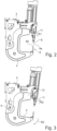
- Fig. 2 and 3 illustrate the relationship between the movement or position of the working piston 11 or the actuating element 10 and the orientation of the base body 4 and thus of the device parts mounted thereon, such as the die unit 6, punch unit 7 and drive unit 9, relative to the holding section 2.
- the actuating element 10 or the working piston 11 or the punch 8 is extended comparatively far in the joining or linear movement direction R1 or towards the die unit 6.
- a free end face 8a of the punch 8 is slightly spaced from an opposite support face 6a of the die unit 6.
- the distance is preferably just large enough at the partial opening that, according to a regularly variable respective height of the component B, the latter can just be inserted between the end face 8a and the support face 6a without collision.
- the joining tongs can be closed in a comparatively short cycle time, with the actual machining of the component starting immediately after closing.
- the Fig. 3 The open position of the device 1 shown is assumed when the actuating element 10 or the working piston 11 or the punch 8 is partially or completely retracted in the direction of movement R2. This can be the case, for example, when a robot arm 3 with the device 1 is moved towards the component B.
- the open position is controlled or automatic depending on the position of the actuating element 10.
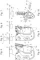
- the component B has sufficient space between the punch unit 7 and the die unit 6 to be inserted or placed, i.e. to be moved laterally back and forth, which Fig. 8 for example, for moving component B in the direction P1 (see Fig. 10 ) between punch unit 7 and die unit 6.
- Figure 7 illustrates that the finished component B is transported or transferred in the direction P2, away from the area between the punch unit 7 and die unit 6, which are sufficiently spaced apart from each other.
- Fig. 10 illustrates that in a synchronized processing of a plurality of components B', B'', B′′′ one after the other, the processing of individual components takes place by transporting the not yet processed component B' in the direction P1 towards the device, the component B" is currently being processed and the component B′′′ has already been processed and is transported away in the direction P2 (see also Fig. 7 ).
- the joining axis S is preferably perpendicular to a surface to be machined on component B.
- Fig. 8 the punch 7 and die unit 6 are moved apart, the device 1 or the joining tongs is opened, and the joining axis S is inclined to the surface of the approaching component B to be machined.
- FIG. 4 to 7 show successive steps on component B during its processing with device 1.
- the respective position of the device 1 in the corresponding processing step of component B is shown in perspective.
- Fig. 4 the component B to be machined is placed on the support side 6a of the die unit 6 with the clinching pliers or device 1 partially opened. The punch 8 is still away from component B.
- the punch 8 designed as a double punch, plunges into the component under a movement of the punch 8 and deforms it in a double clinch point C on the component B.
- the actuating element 10 or the working piston 11 is driven in the direction R1 (see Fig. 5, 9 After forming, the punch 8 moves back in direction R2, away from component B.
- the base body 4 pivots in the direction R3 away from the component B with further movement of the actuating element 10 in the direction R2 (see Fig. 3 ).
- the die unit 6 moves away from the component B in the direction M, which is achieved by pivoting the base body 4 and the elements of the device 1 present thereon in the clockwise direction in the direction R3 (see Fig. 3 ) around the bearing point 5.
- the component B is free from the punch and die unit and is moved further in the transfer direction P2 relative to the die unit 6, which can be done, for example, by a transfer device (not shown).
Landscapes
- Engineering & Computer Science (AREA)
- Mechanical Engineering (AREA)
- Automatic Assembly (AREA)
- Manipulator (AREA)
- Press Drives And Press Lines (AREA)
Description
- Bei Vorrichtungen, wie Werkzeugen zum umformenden Bearbeiten von Werkstücken, Clinch- oder Stanznietzangen oder Fügezangen zum Setzen von Verbindungs- oder Funktionselementen, wie Bolzen oder Muttern, sind für industrielle Anwendungen unterschiedliche Maschinenkonzepte ausgebildet. Die Maschinenkonzepte beziehen sich vorteilhafterweise auch auf das Zuführen und Weiterbewegen der Werkstücke und/oder Bauteile. Solche Vorrichtungen zum Einwirken auf Werkstückabschnitte bzw. zum Durchsetzfügen sind nachfolgend auch allgemein als Fügezangen bezeichnet.
- Als Funktionselemente sind vorzugsweise Einpresselemente zu verstehen, welche im gesetzten Zustand an dem Werkstück eine Zusatzfunktion nach außen aufweisen, beispielsweise einen Verbindungs- oder Befestigungsabschnitt, wie beispielsweise ein Außengewinde zur Verbindung des Verbindungs- oder Befestigungsabschnitts mit einem weiteren Abschnitt.
- Folgende Anwendungen bei den oben beschriebenen Anordnungen sind zum Beispiel zu unterscheiden:
- robotergeführte Fügewerkzeuge an einem Roboter, wobei das Fügewerkzeug durch den Roboter an das Bauteil geführt wird,
- roboterbeschickte Fügezangen, wobei das Bauteil am Roboter vorhanden ist und durch den Roboter an das Fügewerkzeug geführt wird,
- handbeschickte Fügezangen,
- maschinenintegrierte Fügezangen, wobei die Fügezange fixiert ist oder auf räumlich definierten Bewegungsachsen bewegbar ist, und wobei das Bauteil durch z. B. ein Transfersystem wie beispielsweise ein Rundschalttisch oder ein Lineartransfersystem, zu- und/oder abgeführt wird.
- Zum Stand der Technik wird die
DE 92 17 181 U1 genannt. - Aufgabe der vorliegenden Erfindung ist es, die einleitend erläuterten Vorrichtungen bzw. Fügezangen zu verbessern. Insbesondere sollen Freifahrprobleme bei solchen Vorrichtungen auf einfache Weise behoben werden. Außerdem sollen Nachteile aufgrund häufig auftretender kritischer Taktzeiten minimiert werden. Kritische Taktzeiten sind insbesondere durch eine vergleichsweise lange Eintauch- bzw. Annäherungszeit der Fügezange zum Bauteil hin und/oder eine vergleichsweise lange Freifahrzeit der Fügezange vom Bauteil weg gekennzeichnet.
- Diese Aufgabe wird durch den unabhängigen Anspruch gelöst. Die abhängigen Ansprüche thematisieren vorteilhafte und zweckmäßige Weiterbildungen der Erfindung.
- Die Erfindung geht aus von einer Vorrichtung zum Durchsetzfügen eines Bauteils oder zum Setzen eines Fügeelements oder eines Funktionselements an einem Bauteil, umfassend einen Halteabschnitt, mit dem die Vorrichtung an einer Aufnahme in der Umgebung positionierbar ist, und einen Grundkörper, der über eine Lagerstelle am Halteabschnitt gelagert ist, und wobei am Grundkörper eine Matrizeneinheit mit einem Matrizenelement und eine der Matrizeneinheit gegenüberliegende Stempeleinheit mit einem Stempel aufgenommen sind, wobei zur Bewegung des Stempels und/oder des Matrizenelements eine Antriebseinheit vorgesehen ist, die ein linear bewegbares mit dem Stempel oder dem Matrizenelement gekoppeltes Stellelement entlang einer Fügeachse der Vorrichtung reversibel antreibt, um auf das zwischen der Stempeleinheit und der Matrizeneinheit vorhandene Bauteil einzuwirken.
- Nachfolgend wird statt dem Begriff "Vorrichtung" der Begriff "Fügezange" gleichwertig und insbesondere nicht einschränkend auf das Fügen verwendet.
- Der Kern der Erfindung liegt darin, dass der Grundkörper über die Lagerstelle relativ zum Halteabschnitt bewegbar ist und wobei eine Steuereinrichtung zwischen dem Stellelement und dem Halteabschnitt derart ausgebildet ist, dass abhängig von der Position des Stellelements entlang der Fügeachse aufgrund der angetriebenen Bewegung des Stellelements die Stellung des Grundkörpers relativ zum Halteabschnitt vorgegeben ist. Die Steuereinrichtung bildet eine mechanische Kopplung, über welche das Stellelement, zum Beispiel ein Arbeitskolben einer Antriebseinheit mit einer Kolben-Zylinder-Einheit, vorzugsweise dauerhaft mit dem Halteabschnitt, wie einem Halte- oder Maschinengestell, verbunden ist.
- Mit der Steuereinrichtung ist eine Bewegungskopplung zwischen der angetriebenen Linearbewegung des Stellelements und der Bewegung des Grundkörpers relativ zum Halteabschnitt bereitstellbar. Die Linearbewegung des Stellelements erfolgt vorzugsweise relativ zu einem feststehenden Abschnitt, an dem das Stellelement bewegbar gelagert ist. Der feststehende Abschnitt ist zum Beispiel ein das Stellelement umgebendes Gehäuse mit einer Wälzlagereinrichtung zwischen dem Gehäuse und dem Stellelement.
- Vorteilhafterweise lässt sich eine Ausgleichbewegung zum Beispiel eines Abschnitts der Vorrichtung bzw. des Grundkörpers, der mit der Stempelseite und/oder der Matrizenseite verbunden ist, zeitgleich mit dem Arbeitshub der Vorrichtung bzw. der Fügezange ausführen. Vorteilhaft erfolgt die Ausgleichbewegung durch die angetriebene Bewegung des Stempels und/oder durch die angetriebene Bewegung des Matrizenelements. Die Ausgleichbewegung ist insbesondere eine mit der Antriebsbewegung zwangsgekoppelte Bewegung. Dabei ist es vorzugsweise so, dass die Antriebseinheit mitbewegt wird mit dem Grundkörper.
- Mit der vorgeschlagenen Vorrichtung zum Durchsetzfügen oder zum Setzen von Funktionselementen oder Fügeelementen wird beispielsweise bei maschinenintegrierten Vorrichtungen bzw. Fügezangen das Erfordernis erfüllt, eine optimierte Bewegung des Grundkörpers zu ermöglichen, welche insbesondere eine Ausgleichbewegung umfasst.
- Bei maschinenintegrierte Vorrichtungen ergibt sich regelmäßig die Anforderung, eine Bewegung vorzugsweise der gesamten Fügezange in Fügerichtung oder zumindest annähernd in Fügerichtung zu ermöglichen. Dieser Bedarf besteht regelmäßig aufgrund eines notwendigen Herausfahrens der Fügezange aus einem Matrizengesenk, auf dem das Werkstück abgestützt ist, oder aufgrund eines Freifahrens des Bauteils bzw. des Bauteilhalters, um für eine nachfolgende Transferbewegung des Werkstücks einen Freigang zu gewähren. Ein Freifahren der Matrizeneinheit und/oder der Stempeleinheit vom Bauteil weg, wobei das Bauteil vorzugsweise statisch ist, ist damit realisierbar. Vorzugsweise erfolgt das Freifahren der gesamten Vorrichtung weg vom Bauteil simultan mit dem Freifahren der Stempeleinheit vom Bauteil weg und/oder dem Freifahren der Matrizeneinheit vom Bauteil weg.
- Der Halteabschnitt bzw. das Halte- bzw. Maschinengestell ist vorzugsweise integraler Bestandteil einer Gesamtmaschine, wie der gesamten Vorrichtung.
- Mit der erfindungsgemäßen Vorrichtung lassen sich häufig auftretende Anforderungen auch in Kombination erfüllen, zum Beispiel das einmalige Eintauchen der Fügezange in ein Bauteil und/oder im bzw. am Bauteil. Auch das Ausführen mehrerer Fügevorgänge mit vergleichsweise geringem Freifahrhub zwischen einzelnen Bearbeitungsschritten und/oder das Aus- bzw. Wegfahren der Fügezange vom Bauteil und/oder eine Transferoperation zum nächsten Bauteil lassen sich vorteilhafterweise kombiniert erreichen.
- Darüber hinaus lässt sich mit der Erfindung vorzugsweise eine definierte Bewegung der Vorrichtung bzw. Fügezange relativ zum Bauteil während des Fügeprozesses ausführen. Dies ist insbesondere bei einer invertierten Fügerichtung durch Tausch von Stempeleinheit und Matrizeneinheit, was den Antrieb angeht, von Vorteil bzw. notwendig. Dabei ist es bevorzugt bzw. notwendig, dass während des Fügevorgangs das Bauteil räumlich bewegungsfrei bleibt. Hierfür ist es vorzugsweise so, dass während dem Fügevorgang die Fügezange um den Weg, welcher der Stempel bzw. der Niet, das Funktionselement oder das Fügelement in das Bauteil eindringt, synchronisiert gegenbewegt wird. Die Gegenbewegung ist insbesondere in Richtung und/oder Betrag synchronisiert.
- Mit der Erfindung sind insbesondere die folgenden Vorteile erzielbar:
- minimaler bis kein Zeitverlust durch zeitgleiche Bewegungen des Stempels bzw. des Matrizenelements einerseits und des Grundkörpers oder anderer Abschnitte andererseits;
- geringere oder kein Ansteuerungsaufwand nötig für Ausgleichbewegung bzw. für Bewegung des Grundkörpers;
- kein wesentlicher bzw. praxisrelevanter zusätzlicher Energiebedarf bzw. -verbrauch;
- weiterer Zeitvorteil bzw. geringere Taktzeit, da durch eine z. B. Teilöffnung der Fügezange, gegenüber einer größeren Öffnung oder einer Komplettöffnung, die Taktzeit weiter optimierbar bzw. verkürzbar ist, es erfolgen Teil- bzw. Partialhübe sowohl des Stempels als auch des Grundkörpers mit der gekoppelten Bewegung bzw. mit der Ausgleichbewegung bzw. mit der Bewegung des Teils, das sich mit der Antriebsbewegung gekoppelt bewegt;
- technisch und konstruktiv einfache und platzsparende bzw. kompakte Lösung;
- wirtschaftlich vorteilhaft bzw. preisgünstig
- vergleichsweise geringe Fehleranfälligkeit.
- Der Halteabschnitt ist zum Beispiel feststehend, beispielsweise an einem Gebäudeabschnitt aufgenommen. Der Halteabschnitt ist alternativ z.B. bewegbar an einem Roboterarm vorhanden. Das Bauteil z. B. ein plattenartiges Werkstück ist z. B. einlagig oder mehrlagig bzw. besteht aus mehreren Materiallagen.
- Das Stellelement ist vorzugsweise ein Linearbewegungselement wie z. B. ein Teil eines Kolben-Zylinder-Antriebs wie z. B. ein Arbeitskolben der Vorrichtung bzw. der Fügezange. Die Antriebseinheit ist wahlweise insbesondere eine hydropneumatische, pneumatische, hydraulische und/oder eine elektrische Antriebseinheit. Die elektrische Antriebseinheit umfasst vorzugsweise einen Elektromotor vorzugsweise einen elektrischen Spindelantrieb.
- Vorteilhafterweise umfasst die Steuereinrichtung eine Führungsbahn und ein entlang der Führungsbahn bewegbares Führungsorgan, vorzugsweise ein entlang der Führungsbahn verschieblich bewegbares Führungsorgan. Die Führungsbahn kann eine Führungskurve bereitstellen für das kurvengeführte Führungsorgan. Mit der bevorzugt kurven- bzw. bahnführenden Steuereinrichtung erfolgt die Kopplung zwischen angetriebener Bewegung des Stellelements bzw. des Stempels oder des Matrizenelements und dem Halteabschnitt. Damit wird bevorzugterweise die Bewegung oder Stellung insbesondere des Grundkörpers zum Halteabschnitt, abhängig von der Bewegung des Stellelements vorgegeben. Damit ist insbesondere abhängig vom zurückgelegten Fahrweg des Stempels oder des Matrizenelements und damit abhängig von einem Abstand eines angetrieben bewegbaren freien Endes des Stempels und/oder des Matrizenelements zum Bauteil eine Ausgleichbewegung des Grundkörpers einrichtbar.
- Damit lässt sich insbesondere eine mit der Bewegung des Grundkörpers vorgegebene Ausgleichsbewegung, zum Beispiel eine Schwenkbewegung des Grundkörpers um seine Lagerstelle am Halteabschnitt, und damit der Stempel- und/oder Matrizeneinheit vorteilhaft vorgeben vor- und/oder nach der eigentlichen Verformung des Bauteils. Die Ausgleichbewegung ist insbesondere abgestimmt auf die angetriebene Bewegung des Stempels und/oder des Matrizenelements. Ein Bewegungsweg und eine Bewegungsposition des Grundkörpers lassen sich vorzugsweise exakt räumlich und zeitlich wiederholbar einrichten und insbesondere abgleichen mit einer Antriebsbewegung. Der Abgleich erfolgt vorzugsweise in beide entgegengesetzten Richtungen entlang der Führungsbahn. Dabei ist es auch möglich, dass die Steuereinrichtung ausgebildet ist, dass während der Bewegung des Stellelements, also bei laufender Antriebseinheit, eine Phase existiert, in der keine Bewegung des Grundkörpers relativ zum Halteabschnitt stattfindet. Dann erfolgt lediglich eine Relativbewegung zwischen z. B. dem Stempels und dem Bauteil, entsprechend einem üblichen Fügevorgang bei ruhender Matrizeneinheit und ruhendem Niederhalter, der den Stempel umgibt.
- Ein Vorteil liegt darin, dass die Führungsbahn am Halteabschnitt ausgebildet ist. Grundsätzlich kann der Halteabschnitt ein-, zwei- oder mehrteilig sein, bevorzugt einteilig. Beispielsweise kann ein der Antriebseinheit mit dem Stellelement zugewandter Abschnitt des Halteabschnitts die Führungsbahn aufweisen. Der Abschnitt des Halteabschnitts mit der Führungsbahn ist zum Beispiel einem Abschnitt des Halteabschnitts, der an einer festen Einrichtung oder z. B. einem räumlich bewegbaren Roboterarm fixiert ist, abgewandt.
- Die Führungsbahn ist passend abgestimmt, beispielsweise als insbesondere längliche einfache oder doppelte oder mehrfache Kurvenbahn, so dass ein auf die Führungsbahn abgestimmtes Führungselement, beispielsweise ein Stift, eine Rolle oder ein Bolzen, in der Führungsbahn stetig geführt, sanft gleitend bzw. gleichmäßig und ruckfrei bewegbar ist.
- Vorteilhafterweise umfasst die Steuereinrichtung eine Kulissenführung. Die Kulissenführung umfasst vorzugsweise eine Kulissensteuerung mit einem Getriebeelement. Die Kulissenführung, umfassend z. B. eine Führungsbahn am Halteabschnitt und ein entlang der Führungsbahn geführt bewegbares Getriebeelement ist einfach bereitstellbar, platzsparend, stabil und für eine zuverlässig geführte Bewegung vorteilhaft. Das bahngeführte Getriebeelement ist vorzugsweise ein Führungsorgan am Stellelement. Eine Führungsbahn ist vorzugsweise eine Ausnehmung zum Beispiel in der Art eines Langlochs, gerade und/oder gebogen und/oder mit winkligem Verlauf, z. B. in einem dünnen flachen Material wie einem Blechabschnitt. Vorzugsweise sind entsprechende fluchtende Abschnitte der Führungsbahn in zwei gegenüberliegenden vorzugsweise parallel ausgerichteten Blechabschnitten ausgebildet, insbesondere in genau zwei Blechabschnitten, die in Richtung einer Normalen eines Blechabschnitts beabstandet sind und einen freien Zwischenbereich dazwischen aufweisen.
- Die Führungsbahn ist zumindest abschnittsweise in ihrem Verlauf zum Beispiel unstetig und/oder stetig gekrümmt.
- Beispielsweise ist die Führungsbahn zum Beispiel die Kulissen-Führungsbahn derart abgestimmt, dass eine Bewegung des Grundkörpers bzw. eine Bewegung der Stempel- und/oder Matrizeneinheit bzw. eines Matrizenelements der Matrizeneinheit relativ zum Bauteil während des Füge- oder Setzvorgangs vermieden oder nahezu vermieden ist.
- Ein anderer Vorteil ergibt sich, wenn die Steuereinrichtung nach dem Kniehebelprinzip ausgestaltet ist. Damit lassen sich Hebelkräfte und -momente vorteilhaft bereitstellen. Damit wird die Bewegungskopplung zwischen Stellelement und Grundkörper vorteilhaft bereitstellbar. Vorzugsweise ist die mit der Steuereinrichtung bereitstellbare Bewegungskopplung zwischen der angetriebenen Linearbewegung von Stellelement und der Bewegung des Grundkörpers relativ zum Halteabschnitt nach dem Prinzip der Kniehebelkopplung ausgestaltet.
- Es ist darüber hinaus von Vorteil, dass die Steuereinrichtung ein mit dem Stellelement verbundenes Führungsorgan umfasst. Das Führungsorgan ist vorzugsweise fest und vorzugsweise starr mit dem Stellelement verbunden. Das vorzugsweise außen ballige oder konvexe Führungsorgan, wie zum Beispiel ein Stift, eine Rolle, ein Ritzel, ein Reibrad oder ein Bolzen, läuft entlang einer Führungsbahn, wie zum Beispiel der Bahn einer Kulissenführung. Die Führungsbahn weist zum Beispiel ebene oder konturierte, wie zum Beispiel zahnprofilförmige Abschnitte auf, die mit der Außenseite des Führungsorgans in Wirkkontakt gelangen. Entsprechend der Stellelementbewegung, vorzugsweise eine lineare Bewegung, ist das Führungsorgan linear bewegbar mit der Antriebseinheit bzw. bewegt sich fest gekoppelt mit dem Stellelement.
- Erfindungsgemäß umfasst die Lagerstelle ein Drehlager. Ein Drehlager ist einfach, platzsparend und stabil einrichtbar.
- Die mit dem Drehlager ausgebildete Drehachse steht vorzugsweise senkrecht zur Fügeachse bzw. senkrecht zur Bewegungsrichtung des linear bewegbaren Stellelements. Das Drehlager umfasst zum Beispiel einen länglichen Lagerstift, der z. B. lösbar durch Öffnungen am Grundkörper und/oder Halteabschnitt greift, bzw. durch beispielsweise eine auf den Lagerstift passende Lageröffnung oder vorzugsweise durch zwei oder mehr voneinander beabstandete passende Lageröffnungen greift. Die zumindest eine Lageröffnung ist vorzugsweise im Halteabschnitt vorhanden. Das Drehlager ist vorzugsweise als Gleitlager oder als Wälzköperlager ausgestaltet. Beispielsweise umfasst das Drehlager als Lagerstift eine durch zueinander fluchtende Öffnungen axial durchsteckbare und axial sicherbare Schraube z. B. mit aufschraubbarer Mutter.
- Da das Stellelement mit der zum Beispiel Schwenkbewegung des Grundkörpers an der Lagerstelle zum Halteabschnitt bei der angetriebenen Stempel- und/oder Matrizenbewegung mitbewegt wird, sind Bewegungsphasen nicht ausgeschlossen, in denen die räumliche Orientierung bzw. die Neigung der Fügeachse sich verändert.
- Gemäß einer vorteilhaften Variante umfasst die Lagerstelle ein Axiallager. Die Lagerstelle zwischen dem Halteabschnitt wie z. B. einem Halte- bzw. Maschinengestell und dem Grundkörper wie z. B. dem Gegenkraftgestell ist vorzugsweise ein Axiallager umfassend z. B. einen linear verfahrbaren Schlitten. An der Lagerstelle des Grundkörpers am Halteabschnitt kann eine lineare Bewegung z. B. schräg zu einer räumlich festen Raumachse vorgegeben werden. Ein Axiallager wird auch als Längslager, Drucklager oder Spurlager bezeichnet.
- Nach einer Modifikation der Erfindung ist zur mechanischen Entlastung der Steuereinrichtung eine Entlastungseinrichtung vorgesehen. Damit werden Kräfte und/oder Momente, welche an bzw. auf die Bauteil der Steuereinrichtung wirken, wie z. B. eine Führungsbahn und/oder auf das entlang der Führungsbahn bewegbare Führungsorgan reduziert bis in einen unkritischen Bereich, so dass lediglich tolerierbare Reibungseffekte und/oder keine bleibenden bzw. plastischen Verformungen von Teilen der Steuereinrichtung auftreten.
- Die Entlastung umfasst vorzugsweise ein zusätzliches Element, welches insbesondere wirkenden Schwerkrafteinflüssen entgegenwirkt. Ein solches Element stellt Kräfte und/oder Momente bereit und umfasst zum Beispiel eine Feder oder eine Pneumatik-Einrichtung mit einem Pneumatikzylinder und einem Pneumatik-Kolben und/oder eine Hydraulik-Einrichtung. Aufgrund der Konvexform ist auf einfache und stabile Weise das Führungsorgan ausbildbar. Außerdem ist damit das Führungsorgan im Hinblick auf Reibeinflüsse zwischen dem Führungsorgan und Abschnitten der Führungsbahn vorteilhaft gestaltet. Ein Verkanten, ein Rucken oder ein Blockieren des Führungsorgans in der Führungsbahn bei der Bewegung in der Führungsbahn kann vorteilhaft minimiert bzw. vermieden werden.
- Das Führungsorgan ist außen vorzugsweise ballig bzw. zum Beispiel im Querschnitt kreisförmig, elliptisch oder in der Form zylindrisch. Das Führungsorgan ist zum Beispiel als Rolle, Walze, Bolzen oder Stift ausgestaltet.
- Vorteilhaft ist die Steuereinrichtung derart ausgebildet, dass die Stellung des Grundkörpers relativ zum Halteabschnitt während eines Durchsetzfügevorgangs oder während eines Setzvorgangs unverändert bleibt. Dies ist demgemäß in aller Regel nur phasenweise bzw. nicht über die gesamte Zeit des angetrieben fahrenden Stempels bzw. Stellelements der Fall. Damit lässt sich eine gewünschte Betriebsführung optimieren. Insbesondere sind während der angetriebenen Bewegung des Stempels oder des Matrizenelements auch Phasen möglich, in denen der Grundkörper stillsteht, beispielsweise um das Bauteil z. B. durchgehend zu fixieren und/oder zu stützen.
- Auch von Vorteil ist es, wenn die Steuereinrichtung derart ausgebildet ist, dass während eines Durchsetzfügevorgangs oder während eines Setzvorgangs die Richtung und der Betrag der Bewegung der Matrizeneinheit entgegengesetzt der Richtung und dem Betrag der Bewegung des Stempels sind. Dies gilt zum Beispiel für den Fall, dass die Matrizeneinheit auf der wirkenden Seite der Antriebseinheit bzw. des Arbeitskolbens vorhanden ist bzw. wenn auf der Matrizeneinheit-Seite der Antrieb erfolgt bzw. diese angetrieben wird. Die Matrizeneinheit ist dann auf der Seite des Stellelements bzw. dieses ist mit dem angetrieben bewegten Matrizenteil verbunden.
- Das Zeit-Weg-Bewegungsprofil der Matrizeneinheit während des Füge- oder Setzvorgangs entspricht zumindest nahezu dem entgegen gerichteten Bewegungsprofil des Stempels. Damit wird beispielsweise erreicht, dass das Bauteil relativ zum Halteabschnitt bzw. zum Maschinengestell und zum Grundkörper bzw. zum Gegenkraftgestell zumindest nahezu in Ruhe bleibt.
- Schließlich ist es vorteilhaft, dass die Vorrichtung als Fügezange mit einem C-Bügel ausgestaltet ist. Auch gilt dies für alle anderen Vorrichtungen der Erfindung. Diese Anordnung ist eine bewährte Ausbildung. Die C-Bügel-Fügezange ist zum Beispiel wandfixiert oder an einem Roboterarm befestigbar und räumlich bewegbar. Der C-Bügel bildet zumindest im Wesentlichen den Grundkörper.
- Weitere Merkmale und Vorteile der Erfindung sind anhand eines stark schematisiert gezeigten Ausführungsbeispiels näher erläutert. Im Einzelnen zeigt:
- Fig. 1
- eine Seitenansicht einer Vorrichtung zum Durchsetzfügen oder zum Setzen eines Elements,
- Fig. 2
- die Vorrichtung gemäß
Fig. 1 in einem teilgeöffneten Zustand, - Fig. 3
- die Vorrichtung gemäß
Fig. 1 in einem geöffneten Zustand, - Fig. 4
- einen Abschnitt eines Bauteils mit einem daran anliegendem Teil einer Matrizeneinheit der Vorrichtung gemäß
Fig. 1 , - Fig. 5
- den Ausschnitt gemäß
Fig. 4 mit Matrizeneinheit und mit einem Teil einer Stempeleinheit der Vorrichtung gemäßFig. 1 am Ende eines Durchsetzfügevorgangs des Bauteils mit dem dabei umgeformten Bauteil, - Fig. 6
- den Ausschnitt gemäß
Fig. 5 , wobei der Teil der Stempeleinheit wegbewegt ist, - Fig. 7
- den Ausschnitt gemäß
Fig. 6 , wobei der Teil der Matrizeneinheit wegbewegt ist vom Bauteil, - Fig. 8
- die geöffnete Vorrichtung gemäß
Fig. 1 mit einem bearbeitungsbereit positionierten Bauteil beim Heranbewegen an das Bauteil, - Fig. 9
- die Anordnung gemäß
Fig. 8 bei geschlossener Vorrichtung beim Umformen des Bauteils und - Fig. 10
- die Anordnung gemäß
Fig. 9 schräg perspektivisch mit drei Bauteilen, deren Transferbewegung relativ zur Vorrichtung angedeutet ist. -
Fig. 1 zeigt eine vollständig zusammengefahrene bzw. geschlossene Vorrichtung 1 zum Durchsetzfügen eines Bauteils B oder zum Setzen eines Füge-, Funktions- oder Verbindungselements an dem Bauteil B. Die Vorrichtung 1 ist z. B. als Füge-, Clinch- oder Stanzzange ausgebildet. Die Vorrichtung 1 mit einer Fügeachse S ist im konkreten Ausführungsbeispiel als Clinchwerkzeug bzw. Werkzeug zum Clinchen bzw. Durchsetzfügen ausgebildet. - Die Vorrichtung 1 umfasst einen Halteabschnitt 2, mit dem die Vorrichtung 1 an einer gestrichelt angedeuteten Aufnahme 3 wie einem Roboterarm oder einer Wand in der Umgebung positionierbar ist. Der Halteabschnitt 2 dient als Haltegestell oder Maschinengestell. Außerdem weist die Vorrichtung 1 einen Grundkörper 4 auf, der über eine Lagerstelle 5 am Halteabschnitt 2 gelagert ist. Die Lagerstelle 5 ist derart ausgebildet, dass der Grundkörper 4 mindestens einen offenen räumlichen Freiheitsgrad besitzt. Die Lagerstelle 5 ist hier z. B. ein Drehlager mit einer Drehachse D quer zur Fügeachse S.
- Der Grundkörper 4 ist vorzugsweise als C-Gestell oder C-Bügel gestaltet und dient als Gegenkraftgestell zum Halteabschnitt 2.
- Am Grundkörper 4 sind eine Matrizeneinheit 6 und eine der Matrizeneinheit 6 gegenüberliegende Stempeleinheit 7 mit einem Stempel 8 aufgenommen. Zur reversiblen Bewegung des Stempels 8 ist eine Antriebseinheit 9 vorgesehen, die ein linear bewegbares mit dem Stempel 8 gekoppeltes Stellelement 10 entlang der Fügeachse S der Vorrichtung 1 reversibel antreibt, um auf ein zwischen der Stempeleinheit 7 und der Matrizeneinheit 6 vorhandenes Bauteil B einzuwirken (s.
Fig. 4-10 ). - Mit der Antriebseinheit 9, zum Beispiel ein Pressantrieb, wird das Stellelement 10 angetrieben, das im Ausführungsbeispiel von einem entlang der Fügeachse S linear mit der Antriebseinheit 9 angetrieben bewegbaren Arbeitskolben 11 gebildet wird. Das Stellelement 10 bzw. der Arbeitskolben 11 ist vorne mit dem Stempel 8 verbunden.
- Die Fügeachse S ist eine Bewegungsachse bzw. fällt mit der zentrischen Längsachse des Stellelements 10 bzw. des Arbeitskolbens 11 und des Stempels 8 zusammen und geht durch die Matrizeneinheit 6 (s.
Fig. 1 ). - Der Grundkörper 4 ist über die Lagerstelle 5 relativ zum Halteabschnitt 2 bewegbar bzw. um die Drehachse D hin und her schwenkbar. Es ist weiter eine mechanische Kopplung vorhanden, die als Steuereinrichtung 12 zwischen dem Stellelement 10 und dem Halteabschnitt 2 ausgebildet ist. Die Steuereinrichtung 12 gibt vor, dass abhängig von der Position des Stellelements 10 entlang der Fügeachse S aufgrund der angetriebenen Bewegung des Stellelements 10 die Stellung des Grundkörpers 4 relativ zum Halteabschnitt 2 vorgegeben ist.
- Es ist weiter ein zusätzliches Element als Entlastungseinrichtung 13 vorhanden, um eine mechanische Entlastung von Elementen der Steuereinrichtung 12 bereitzustellen, insbesondere hinsichtlich dynamischer und statischer Belastungen bzw. Schwerkrafteinflüssen.
- Die Steuereinrichtung 12 umfasst eine Führungsbahn 14 und ein entlang der Führungsbahn 14 bewegbares bzw. verschiebliches Führungsorgan 15. Die Führungsbahn 14 ist z. B. eine Kulissenbahn einer Kulissenführung und ist an genau einem oder an zwei gegenüberliegenden Blechabschnitten des Halteabschnitts 2 in einem Bereich ausgebildet, der an die Antriebseinheit 9 mit dem Stellelement 10 heranreicht. Die Führungsbahn 14 weist beispielhaft einen geraden Bahnabschnitt auf, der schräg zur Fügeachse S ausgerichtet ist, welcher über einen gekrümmten Bahnabschnitt in einen kürzeren weiteren geraden Bahnabschnitt übergeht. Der kürzere Bahnabschnitt ist hier in Richtung der Fügeachse S ausgerichtet.
- Das Führungsorgan 15 ist beispielsweise ein Bolzen, der mit dem Stellelement 10 bzw. mit dem Arbeitskolben 11 verbunden ist. Eine Längsachse des Bolzens ist quer zur Längsachse des Arbeitskolbens 11 ausgerichtet.
- Die
Fig. 2 und 3 verdeutlichen den Zusammenhang der Bewegung bzw. Stellung des Arbeitskolbens 11 bzw. des Stellelements 10 und der Ausrichtung des Grundkörpers 4 und damit der daran aufgenommenen Vorrichtungsteile wie Matrizeneinheit 6, Stempeleinheit 7 und Antriebseinheit 9, relativ zum Halteabschnitt 2. - Bei einer in
Fig. 2 teilgeöffneten Vorrichtung 1 ist das Stellelement 10 bzw. der Arbeitskolben 11 bzw. der Stempel 8 vergleichsweise weit ausgefahren in Füge- bzw. linearer Bewegungsrichtung R1 bzw. zur Matrizeneinheit 6 hin. Zum Beispiel ist eine freie Stirnseite 8a des Stempels 8 von einer gegenüberliegenden Auflageseite 6a der Matrizeneinheit 6 etwas beabstandet. Der Abstand ist vorzugsweise bei der Teilöffnung gerade so groß, dass gemäß einer regelmäßig variablen jeweiligen Höhe des Bauteils B dieses zwischen der Stirnseite 8a und der Auflageseite 6a gerade noch kollisionsfrei einbringbar ist. Dann ist in vergleichsweise kurzer Taktzeit die Fügezange schließbar, wobei unmittelbar nach dem Schließen der eigentliche Bearbeitungsvorgang des Bauteils beginnt. - Vor und nach dem eigentlichen Bearbeitungsvorgang am Bauteil B wird die gemäß
Fig. 3 gezeigte geöffnete Stellung der Vorrichtung 1 bei teilweise oder ganz in Bewegungsrichtung R2 zurückgefahrenem Stellelement 10 bzw. der Arbeitskolben 11 bzw. der Stempel 8 eingenommen. Dies kann z. B. bei einem an das Bauteil B herangefahrenen Roboterarm 3 mit der Vorrichtung 1 der Fall sein. Die geöffnete Stellung erfolgt gesteuert bzw. selbsttätig abhängig von der Stellung des Stellelements 10. Das Bauteil B hat genügend Platz zwischen der Stempeleinheit 7 und der Matrizeneinheit 6 eingebracht bzw. platziert zu werden, also seitlich hin- und wieder wegbewegt zu werden, wasFig. 8 zum Beispiel für das Hinbewegen des Bauteils B in Richtung P1 (s.Fig. 10 ) zwischen Stempeleinheit 7 und Matrizeneinheit 6 zeigt.Figur 7 verdeutlicht, dass das fertig bearbeitete Bauteil B in Richtung P2 weitertransportiert bzw. transferiert wird, weg aus dem Bereich zwischen den dabei ausreichend weit voneinander beabstandeten Stempeleinheit 7 und Matrizeneinheit 6. -
Fig. 10 verdeutlicht, dass bei einer getakteten Bearbeitung von einer Mehrzahl von Bauteilen B', B'', B‴ nacheinander die Bearbeitung jeweils einzelner Bauteile durch Transport in die Richtung P1 des noch nicht bearbeiteten Bauteils B' zur Vorrichtung hin erfolgt, das Bauteil B" gerade bearbeitet wird und das Bauteil B‴ bereits bearbeitet ist und in Richtung P2 wegtransportiert wird (s. auchFig. 7 ). - Gemäß der Bearbeitungsstellung bei geschlossener Vorrichtung 1 aus
Fig. 5 und 9 steht die Fügeachse S vorzugsweise senkrecht zu einer am Bauteil B zu bearbeitenden Fläche. - Gemäß
Fig. 8 sind Stempel- 7 und Matrizeneinheit 6 auseinander gefahren, die Vorrichtung 1 bzw. die Fügezange ist geöffnet, und die Fügeachse S steht schräg zur am Bauteil B zu bearbeitenden Fläche des heranbewegten Bauteils B. - Die
Fig. 4 bis 7 zeigen nacheinander ablaufende Schritte am Bauteil B bei dessen Bearbeitung mit der Vorrichtung 1. In denFiguren 8-10 ist perspektivisch die jeweilige Stellung der Vorrichtung 1 im dazugehörigen Bearbeitungsschritt des Bauteils B dargestellt. - Gemäß
Fig. 4 ist das zu bearbeitende Bauteil B aufgelegt auf der Auflageseite 6a der Matrizeneinheit 6 bei teils geöffneter Clinchzange bzw. teil geöffneter Vorrichtung 1. Der Stempel 8 ist noch entfernt vom Bauteil B. - Gemäß
Fig. 5 taucht der als Doppelstempel ausgebildete Stempel 8 unter einer Bewegung des Stempels 8 in das Bauteil ein und verformt dieses in einem Doppel-Clinchpunkt C am Bauteil B. Dabei fährt das Stellelement 10 bzw. der Arbeitskolben 11 angetrieben in Richtung R1 (s.Fig. 5, 9 ). Nach der Umformung fährt der Stempel 8 angetrieben zurück in Richtung R2, weg vom Bauteil B. - Dabei schwenkt gekoppelt über die Steuereinrichtung 12 der Grundkörper 4 in Richtung R3 weg von dem Bauteil B unter weiterer Bewegung des Stellelements 10 in Richtung R2 (s.
Fig. 3 ). Die Matrizeneinheit 6 entfernt sich vom Bauteil B in Richtung M was durch das Schwenken des Grundkörpers 4 und der daran vorhandenen Elemente der Vorrichtung 1 im Uhrzeigersinn in Richtung R3 (s.Fig. 3 ) um die Lagerstelle 5 erfolgt. Das Bauteil B ist frei von Stempel- und Matrizeneinheit und wird in Transferrichtung P2 weiterbewegt relativ zur Matrizeneinheit 6, was durch z. B. eine Transfereinrichtung (nicht gezeigt) erfolgen kann. -
- 1
- Vorrichtung
- 2
- Halteabschnitt
- 3
- Aufnahme
- 4
- Grundkörper
- 5
- Lagerstelle
- 6
- Matrizeneinheit
- 6a
- Auflageseite
- 7
- Stempeleinheit
- 8
- Stempel
- 8a
- Stirnseite
- 9
- Antriebseinheit
- 10
- Stellelement
- 11
- Arbeitskolben
- 12
- Steuereinrichtung
- 13
- Entlastungseinrichtung
- 14
- Führungsbahn
- 15
- Führungsorgan
Claims (12)
- Vorrichtung (1) zum Durchsetzfügen eines Bauteils oder zum Setzen eines Fügeelements oder eines Funktionselements an einem Bauteil, umfassend einen Halteabschnitt (2), mit dem die Vorrichtung (1) an einer Aufnahme (3) in der Umgebung positionierbar ist, und einen Grundkörper (4), der über eine Lagerstelle (5) am Halteabschnitt (2) gelagert ist, und wobei am Grundkörper (4) eine Matrizeneinheit (6) mit einem Matrizenelement und eine der Matrizeneinheit (6) gegenüberliegende Stempeleinheit (7) mit einem Stempel (8) aufgenommen sind, wobei zur Bewegung des Stempels (8) und/oder des Matrizenelements eine Antriebseinheit (9) vorgesehen ist, die ein linear bewegbares mit dem Stempel (8) oder dem Matrizenelement gekoppeltes Stellelement (10) entlang einer Fügeachse der Vorrichtung (1) reversibel antreibt, um auf das zwischen der Stempeleinheit (7) und der Matrizeneinheit (6) vorhandene Bauteil einzuwirken, wobei der Grundkörper (4) über die Lagerstelle (5) relativ zum Halteabschnitt (2) bewegbar ist und wobei eine Steuereinrichtung (12) zwischen dem Stellelement (10) und dem Halteabschnitt (2) derart ausgebildet ist, dass abhängig von der Position des Stellelements (10) entlang der Fügeachse aufgrund der angetriebenen Bewegung des Stellelements (10) die Stellung des Grundkörpers (4) relativ zum Halteabschnitt (2) vorgegeben ist, dadurch gekennzeichnet, dass die Lagerstelle (5) ein Drehlager umfasst.
- Vorrichtung nach Anspruch 1, dadurch gekennzeichnet, dass die Steuereinrichtung (12) eine Führungsbahn (14) und ein entlang der Führungsbahn (14) bewegbares Führungsorgan (15) umfasst.
- Vorrichtung nach Anspruch 1 oder Anspruch 2, dadurch gekennzeichnet, dass die Führungsbahn (14) am Halteabschnitt (2) ausgebildet ist.
- Vorrichtung nach einem der vorhergehenden Ansprüche, dadurch gekennzeichnet, dass die Steuereinrichtung (12) eine Kulissenführung umfasst.
- Vorrichtung nach einem der vorhergehenden Ansprüche, dadurch gekennzeichnet, dass die Steuereinrichtung (12) nach dem Kniehebelprinzip ausgestaltet ist.
- Vorrichtung nach einem der vorhergehenden Ansprüche, dadurch gekennzeichnet, dass die Steuereinrichtung (12) ein mit dem Stellelement (10) verbundenes Führungsorgan (15) umfasst.
- Vorrichtung nach einem der vorhergehenden Ansprüche, dadurch gekennzeichnet, dass die Lagerstelle (5) ein Axiallager umfasst.
- Vorrichtung nach einem der vorhergehenden Ansprüche, dadurch gekennzeichnet, dass zur mechanischen Entlastung der Steuereinrichtung (12) eine Entlastungseinrichtung (13) vorgesehen ist.
- Vorrichtung nach einem der vorhergehenden Ansprüche, dadurch gekennzeichnet, dass das Führungsorgan (15) außen konvex geformt ist.
- Vorrichtung nach einem der vorhergehenden Ansprüche, dadurch gekennzeichnet, dass die Steuereinrichtung (12) derart ausgebildet ist, dass die Stellung des Grundkörper (4) relativ zum Halteabschnitt (2) während eines Durchsetzfügevorgangs oder während eines Setzvorgangs unverändert bleibt.
- Vorrichtung nach einem der vorhergehenden Ansprüche, dadurch gekennzeichnet, dass die Steuereinrichtung (12) derart ausgebildet ist, dass während eines Durchsetzfügevorgangs oder während eines Setzvorgangs die Richtung und der Betrag der Bewegung der Matrizeneinheit (6) entgegengesetzt der Richtung und dem Betrag der Bewegung des Stempels (8) sind.
- Vorrichtung nach einem der vorhergehenden Ansprüche, dadurch gekennzeichnet, dass die Vorrichtung (1) als Fügezange mit einem C-Bügel ausgestaltet ist.
Applications Claiming Priority (2)
| Application Number | Priority Date | Filing Date | Title |
|---|---|---|---|
| DE102021120409.7A DE102021120409A1 (de) | 2021-08-05 | 2021-08-05 | Vorrichtung zum Durchsetzfügen |
| PCT/EP2022/071151 WO2023012017A1 (de) | 2021-08-05 | 2022-07-28 | Vorrichtung zum durchsetzfügen |
Publications (2)
| Publication Number | Publication Date |
|---|---|
| EP4380738A1 EP4380738A1 (de) | 2024-06-12 |
| EP4380738B1 true EP4380738B1 (de) | 2025-06-18 |
Family
ID=83115481
Family Applications (1)
| Application Number | Title | Priority Date | Filing Date |
|---|---|---|---|
| EP22761060.7A Active EP4380738B1 (de) | 2021-08-05 | 2022-07-28 | Vorrichtung zum durchsetzfügen |
Country Status (5)
| Country | Link |
|---|---|
| US (1) | US12214412B2 (de) |
| EP (1) | EP4380738B1 (de) |
| CN (1) | CN117794658A (de) |
| DE (1) | DE102021120409A1 (de) |
| WO (1) | WO2023012017A1 (de) |
Families Citing this family (2)
| Publication number | Priority date | Publication date | Assignee | Title |
|---|---|---|---|---|
| DE102023132519A1 (de) | 2023-11-22 | 2025-05-22 | Schaeffler Technologies AG & Co. KG | Elektromotor |
| DE102023132520A1 (de) | 2023-11-22 | 2025-05-22 | Schaeffler Technologies AG & Co. KG | Elektromotor und Verfahren zur Montage eines Elektromotors |
Family Cites Families (10)
| Publication number | Priority date | Publication date | Assignee | Title |
|---|---|---|---|---|
| US2487262A (en) * | 1945-04-02 | 1949-11-08 | Mueller Otto | Force applying tool |
| DE9217181U1 (de) * | 1992-12-16 | 1993-04-01 | RAS GmbH, 5239 Nistertal | Vorrichtung zum Verbinden von zwei oder mehreren aufeinanderliegenden, flächigen Blechteilen durch Fliesverformung |
| DE29910335U1 (de) * | 1999-06-14 | 1999-09-16 | Emhart Inc., Newark, Del. | Einrichtung zur Ausführung von mechanischen Arbeiten an Bauteilen mittels Werkzeugelemente, welche auf einem, vorzugsweise C-förmigen, Werkzeughalter angeordnet sind |
| DE102005009526A1 (de) | 2005-03-02 | 2006-09-07 | Böllhoff Verbindungstechnik GmbH | Verfahren und Vorrichtung zum Steuern/Regeln der Zustellbewegung eines Fügewerkzeuges |
| US9027220B2 (en) * | 2012-08-07 | 2015-05-12 | Newfrey Llc | Rivet setting machine |
| DE102014200962A1 (de) | 2014-01-21 | 2015-07-23 | Bayerische Motoren Werke Aktiengesellschaft | Fügevorrichtung, vorzugsweise zum Setzen von Nieten, zum Clinchen oder zum Stanzen |
| DE102015007295B3 (de) * | 2015-06-10 | 2016-09-08 | Audi Ag | Setzvorrichtung |
| DE102017220816A1 (de) * | 2017-11-22 | 2019-05-23 | Robert Bosch Gmbh | Fügevorrichtung und verfahren zum fügen mindestens eines bauteils unter verwendung einer x-zange |
| DE102018205526A1 (de) | 2018-04-12 | 2019-10-17 | Robert Bosch Gmbh | Stanznietvorrichtungen |
| DE102018205621A1 (de) * | 2018-04-13 | 2019-10-17 | Robert Bosch Gmbh | Stanznietvorrichtung mit Zuführeinheit für Niete |
-
2021
- 2021-08-05 DE DE102021120409.7A patent/DE102021120409A1/de active Pending
-
2022
- 2022-07-28 EP EP22761060.7A patent/EP4380738B1/de active Active
- 2022-07-28 WO PCT/EP2022/071151 patent/WO2023012017A1/de not_active Ceased
- 2022-07-28 CN CN202280054796.1A patent/CN117794658A/zh active Pending
-
2024
- 2024-01-12 US US18/411,311 patent/US12214412B2/en active Active
Also Published As
| Publication number | Publication date |
|---|---|
| US20240139797A1 (en) | 2024-05-02 |
| DE102021120409A1 (de) | 2023-02-09 |
| US12214412B2 (en) | 2025-02-04 |
| EP4380738A1 (de) | 2024-06-12 |
| WO2023012017A1 (de) | 2023-02-09 |
| CN117794658A (zh) | 2024-03-29 |
Similar Documents
| Publication | Publication Date | Title |
|---|---|---|
| DE69001202T2 (de) | Werkzeuganlage zum nieten von werkstuecken. | |
| DE3819338C2 (de) | Vorrichtung zur Festlegung einer Position bezüglich eines benachbart der Vorrichtung angeordneten dreidimensionalen Gegenstands | |
| DE102017203943B4 (de) | Setzeinheit und Verfahren zum Setzen eines Verbindungselements an einem Werkstück | |
| DE69708834T2 (de) | Formgesenk von dünnen Blech | |
| EP3242760B1 (de) | Vorrichtung und verfahren zum setzen eines verbindungselements an einem werkstück | |
| DE3438584A1 (de) | Vorrichtung zum vernieten von zwei oder mehr blechen einer blechkonstruktion | |
| EP3448597B1 (de) | Transportverfahren zum umsetzen von werkstücken | |
| DE3925370A1 (de) | Materialvorschubvorrichtung fuer schmiedemaschinen u. dgl. | |
| EP4380738A1 (de) | Vorrichtung zum durchsetzfügen | |
| EP3681655B1 (de) | Vorrichtung sowie ein verfahren zum setzen eines verbindungselements an einem werkstück | |
| DE3117293A1 (de) | Einrichtung zum schneiden linear bewegten materials in einzellaengen | |
| EP3515626A1 (de) | Werkzeugmaschine und verfahren zum bearbeiten von plattenförmigen werkstücken | |
| CH712402A1 (de) | Transportvorrichtung mit Greifzangen zum Umsetzen von Werkstücken in einer mindestens zwei Stufen umfassenden Umformeinrichtung. | |
| EP3515617B1 (de) | Werkzeug und werkzeugmaschine sowie verfahren zum bearbeiten von plattenförmigen werkstücken | |
| EP1056556B1 (de) | Bördeleinrichtung mit press- und spannelementen | |
| DE7827272U1 (de) | Vorschubeinrichtung | |
| EP1702692B1 (de) | Bördelvorrichtung | |
| DE3137811A1 (de) | Klemmvorrichtung | |
| DE19545129C2 (de) | Vorrichtung zur Herstellung von stabförmigen Gegenständen | |
| DE10063154B4 (de) | Schmiedepresse mit Stellvorrichtung auf Matrizenseite | |
| DE1802629C3 (de) | Vorrichtung zum Überführen von Werkstücken zwischen aufeinanderfolgenden Bearbeitungsstationen an Pressen und dergleichen Werkzeugmaschinen | |
| DE3703700C2 (de) | Stanzpresse mit einer automatischen Werkzeugwechselvorrichtung | |
| EP2274114B1 (de) | Transporteinrichtung mit positionieranschlag | |
| DE3021332A1 (de) | Vorrichtung zum verbinden wneigstens zweier bauteile durch ein schnitt-umform-verfahren | |
| EP1402968A1 (de) | Boerdelvorrichtung |
Legal Events
| Date | Code | Title | Description |
|---|---|---|---|
| STAA | Information on the status of an ep patent application or granted ep patent |
Free format text: STATUS: UNKNOWN |
|
| STAA | Information on the status of an ep patent application or granted ep patent |
Free format text: STATUS: THE INTERNATIONAL PUBLICATION HAS BEEN MADE |
|
| PUAI | Public reference made under article 153(3) epc to a published international application that has entered the european phase |
Free format text: ORIGINAL CODE: 0009012 |
|
| STAA | Information on the status of an ep patent application or granted ep patent |
Free format text: STATUS: REQUEST FOR EXAMINATION WAS MADE |
|
| 17P | Request for examination filed |
Effective date: 20240223 |
|
| AK | Designated contracting states |
Kind code of ref document: A1 Designated state(s): AL AT BE BG CH CY CZ DE DK EE ES FI FR GB GR HR HU IE IS IT LI LT LU LV MC MK MT NL NO PL PT RO RS SE SI SK SM TR |
|
| DAV | Request for validation of the european patent (deleted) | ||
| DAX | Request for extension of the european patent (deleted) | ||
| GRAP | Despatch of communication of intention to grant a patent |
Free format text: ORIGINAL CODE: EPIDOSNIGR1 |
|
| STAA | Information on the status of an ep patent application or granted ep patent |
Free format text: STATUS: GRANT OF PATENT IS INTENDED |
|
| RIC1 | Information provided on ipc code assigned before grant |
Ipc: B23P 19/06 20060101ALN20250210BHEP Ipc: B21J 15/28 20060101ALI20250210BHEP Ipc: B21J 15/02 20060101ALI20250210BHEP Ipc: B21J 15/30 20060101ALI20250210BHEP Ipc: B21D 39/03 20060101AFI20250210BHEP |
|
| INTG | Intention to grant announced |
Effective date: 20250221 |
|
| GRAS | Grant fee paid |
Free format text: ORIGINAL CODE: EPIDOSNIGR3 |
|
| GRAA | (expected) grant |
Free format text: ORIGINAL CODE: 0009210 |
|
| STAA | Information on the status of an ep patent application or granted ep patent |
Free format text: STATUS: THE PATENT HAS BEEN GRANTED |
|
| AK | Designated contracting states |
Kind code of ref document: B1 Designated state(s): AL AT BE BG CH CY CZ DE DK EE ES FI FR GB GR HR HU IE IS IT LI LT LU LV MC MK MT NL NO PL PT RO RS SE SI SK SM TR |
|
| REG | Reference to a national code |
Ref country code: GB Ref legal event code: FG4D Free format text: NOT ENGLISH |
|
| REG | Reference to a national code |
Ref country code: CH Ref legal event code: EP |
|
| REG | Reference to a national code |
Ref country code: DE Ref legal event code: R096 Ref document number: 502022004356 Country of ref document: DE |
|
| REG | Reference to a national code |
Ref country code: DE Ref legal event code: R081 Ref document number: 502022004356 Country of ref document: DE Owner name: TOX PRESSOTECHNIK SE & CO. KG, DE Free format text: FORMER OWNER: ANMELDERANGABEN UNKLAR / UNVOLLSTAENDIG, 80297 MUENCHEN, DE |
|
| REG | Reference to a national code |
Ref country code: CH Ref legal event code: EP |
|
| REG | Reference to a national code |
Ref country code: IE Ref legal event code: FG4D Free format text: LANGUAGE OF EP DOCUMENT: GERMAN |
|
| PG25 | Lapsed in a contracting state [announced via postgrant information from national office to epo] |
Ref country code: FI Free format text: LAPSE BECAUSE OF FAILURE TO SUBMIT A TRANSLATION OF THE DESCRIPTION OR TO PAY THE FEE WITHIN THE PRESCRIBED TIME-LIMIT Effective date: 20250618 |
|
| PGFP | Annual fee paid to national office [announced via postgrant information from national office to epo] |
Ref country code: DE Payment date: 20250709 Year of fee payment: 4 |
|
| REG | Reference to a national code |
Ref country code: LT Ref legal event code: MG9D |
|
| PG25 | Lapsed in a contracting state [announced via postgrant information from national office to epo] |
Ref country code: GR Free format text: LAPSE BECAUSE OF FAILURE TO SUBMIT A TRANSLATION OF THE DESCRIPTION OR TO PAY THE FEE WITHIN THE PRESCRIBED TIME-LIMIT Effective date: 20250919 Ref country code: NO Free format text: LAPSE BECAUSE OF FAILURE TO SUBMIT A TRANSLATION OF THE DESCRIPTION OR TO PAY THE FEE WITHIN THE PRESCRIBED TIME-LIMIT Effective date: 20250918 |
|
| PG25 | Lapsed in a contracting state [announced via postgrant information from national office to epo] |
Ref country code: BG Free format text: LAPSE BECAUSE OF FAILURE TO SUBMIT A TRANSLATION OF THE DESCRIPTION OR TO PAY THE FEE WITHIN THE PRESCRIBED TIME-LIMIT Effective date: 20250618 |
|
| PG25 | Lapsed in a contracting state [announced via postgrant information from national office to epo] |
Ref country code: HR Free format text: LAPSE BECAUSE OF FAILURE TO SUBMIT A TRANSLATION OF THE DESCRIPTION OR TO PAY THE FEE WITHIN THE PRESCRIBED TIME-LIMIT Effective date: 20250618 |
|
| PGFP | Annual fee paid to national office [announced via postgrant information from national office to epo] |
Ref country code: AT Payment date: 20251020 Year of fee payment: 4 |
|
| PG25 | Lapsed in a contracting state [announced via postgrant information from national office to epo] |
Ref country code: RS Free format text: LAPSE BECAUSE OF FAILURE TO SUBMIT A TRANSLATION OF THE DESCRIPTION OR TO PAY THE FEE WITHIN THE PRESCRIBED TIME-LIMIT Effective date: 20250918 |
|
| REG | Reference to a national code |
Ref country code: NL Ref legal event code: MP Effective date: 20250618 |
|
| PG25 | Lapsed in a contracting state [announced via postgrant information from national office to epo] |
Ref country code: LV Free format text: LAPSE BECAUSE OF FAILURE TO SUBMIT A TRANSLATION OF THE DESCRIPTION OR TO PAY THE FEE WITHIN THE PRESCRIBED TIME-LIMIT Effective date: 20250618 |
|
| PG25 | Lapsed in a contracting state [announced via postgrant information from national office to epo] |
Ref country code: NL Free format text: LAPSE BECAUSE OF FAILURE TO SUBMIT A TRANSLATION OF THE DESCRIPTION OR TO PAY THE FEE WITHIN THE PRESCRIBED TIME-LIMIT Effective date: 20250618 |
|
| PG25 | Lapsed in a contracting state [announced via postgrant information from national office to epo] |
Ref country code: PT Free format text: LAPSE BECAUSE OF FAILURE TO SUBMIT A TRANSLATION OF THE DESCRIPTION OR TO PAY THE FEE WITHIN THE PRESCRIBED TIME-LIMIT Effective date: 20251020 |
|
| PG25 | Lapsed in a contracting state [announced via postgrant information from national office to epo] |
Ref country code: IS Free format text: LAPSE BECAUSE OF FAILURE TO SUBMIT A TRANSLATION OF THE DESCRIPTION OR TO PAY THE FEE WITHIN THE PRESCRIBED TIME-LIMIT Effective date: 20251018 |
|
| PG25 | Lapsed in a contracting state [announced via postgrant information from national office to epo] |
Ref country code: SM Free format text: LAPSE BECAUSE OF FAILURE TO SUBMIT A TRANSLATION OF THE DESCRIPTION OR TO PAY THE FEE WITHIN THE PRESCRIBED TIME-LIMIT Effective date: 20250618 |
|
| PG25 | Lapsed in a contracting state [announced via postgrant information from national office to epo] |
Ref country code: CZ Free format text: LAPSE BECAUSE OF FAILURE TO SUBMIT A TRANSLATION OF THE DESCRIPTION OR TO PAY THE FEE WITHIN THE PRESCRIBED TIME-LIMIT Effective date: 20250618 |
|
| PG25 | Lapsed in a contracting state [announced via postgrant information from national office to epo] |
Ref country code: PL Free format text: LAPSE BECAUSE OF FAILURE TO SUBMIT A TRANSLATION OF THE DESCRIPTION OR TO PAY THE FEE WITHIN THE PRESCRIBED TIME-LIMIT Effective date: 20250618 |
|
| PG25 | Lapsed in a contracting state [announced via postgrant information from national office to epo] |
Ref country code: EE Free format text: LAPSE BECAUSE OF FAILURE TO SUBMIT A TRANSLATION OF THE DESCRIPTION OR TO PAY THE FEE WITHIN THE PRESCRIBED TIME-LIMIT Effective date: 20250618 |
|
| PG25 | Lapsed in a contracting state [announced via postgrant information from national office to epo] |
Ref country code: SK Free format text: LAPSE BECAUSE OF FAILURE TO SUBMIT A TRANSLATION OF THE DESCRIPTION OR TO PAY THE FEE WITHIN THE PRESCRIBED TIME-LIMIT Effective date: 20250618 |
|
| PG25 | Lapsed in a contracting state [announced via postgrant information from national office to epo] |
Ref country code: ES Free format text: LAPSE BECAUSE OF FAILURE TO SUBMIT A TRANSLATION OF THE DESCRIPTION OR TO PAY THE FEE WITHIN THE PRESCRIBED TIME-LIMIT Effective date: 20250618 |
|
| REG | Reference to a national code |
Ref country code: CH Ref legal event code: H13 Free format text: ST27 STATUS EVENT CODE: U-0-0-H10-H13 (AS PROVIDED BY THE NATIONAL OFFICE) Effective date: 20260224 |
|
| PG25 | Lapsed in a contracting state [announced via postgrant information from national office to epo] |
Ref country code: RO Free format text: LAPSE BECAUSE OF FAILURE TO SUBMIT A TRANSLATION OF THE DESCRIPTION OR TO PAY THE FEE WITHIN THE PRESCRIBED TIME-LIMIT Effective date: 20250618 Ref country code: LU Free format text: LAPSE BECAUSE OF NON-PAYMENT OF DUE FEES Effective date: 20250728 |
|
| REG | Reference to a national code |
Ref country code: DE Ref legal event code: R097 Ref document number: 502022004356 Country of ref document: DE |
|
| REG | Reference to a national code |
Ref country code: BE Ref legal event code: MM Effective date: 20250731 |
|
| PG25 | Lapsed in a contracting state [announced via postgrant information from national office to epo] |
Ref country code: MC Free format text: LAPSE BECAUSE OF FAILURE TO SUBMIT A TRANSLATION OF THE DESCRIPTION OR TO PAY THE FEE WITHIN THE PRESCRIBED TIME-LIMIT Effective date: 20250618 |
|
| PG25 | Lapsed in a contracting state [announced via postgrant information from national office to epo] |
Ref country code: DK Free format text: LAPSE BECAUSE OF FAILURE TO SUBMIT A TRANSLATION OF THE DESCRIPTION OR TO PAY THE FEE WITHIN THE PRESCRIBED TIME-LIMIT Effective date: 20250618 |
|
| PG25 | Lapsed in a contracting state [announced via postgrant information from national office to epo] |
Ref country code: BE Free format text: LAPSE BECAUSE OF NON-PAYMENT OF DUE FEES Effective date: 20250731 Ref country code: IT Free format text: LAPSE BECAUSE OF FAILURE TO SUBMIT A TRANSLATION OF THE DESCRIPTION OR TO PAY THE FEE WITHIN THE PRESCRIBED TIME-LIMIT Effective date: 20250618 |
|
| PG25 | Lapsed in a contracting state [announced via postgrant information from national office to epo] |
Ref country code: CH Free format text: LAPSE BECAUSE OF NON-PAYMENT OF DUE FEES Effective date: 20250731 |
|
| PLBE | No opposition filed within time limit |
Free format text: ORIGINAL CODE: 0009261 |
|
| STAA | Information on the status of an ep patent application or granted ep patent |
Free format text: STATUS: NO OPPOSITION FILED WITHIN TIME LIMIT |
|
| REG | Reference to a national code |
Ref country code: CH Ref legal event code: L10 Free format text: ST27 STATUS EVENT CODE: U-0-0-L10-L00 (AS PROVIDED BY THE NATIONAL OFFICE) Effective date: 20260430 |
|
| 26N | No opposition filed |
Effective date: 20260319 |
|
| PG25 | Lapsed in a contracting state [announced via postgrant information from national office to epo] |
Ref country code: LT Free format text: LAPSE BECAUSE OF FAILURE TO SUBMIT A TRANSLATION OF THE DESCRIPTION OR TO PAY THE FEE WITHIN THE PRESCRIBED TIME-LIMIT Effective date: 20250618 |
|
| PG25 | Lapsed in a contracting state [announced via postgrant information from national office to epo] |
Ref country code: IE Free format text: LAPSE BECAUSE OF NON-PAYMENT OF DUE FEES Effective date: 20250728 |
|
| PG25 | Lapsed in a contracting state [announced via postgrant information from national office to epo] |
Ref country code: FR Free format text: LAPSE BECAUSE OF NON-PAYMENT OF DUE FEES Effective date: 20250818 |
|
| PG25 | Lapsed in a contracting state [announced via postgrant information from national office to epo] |
Ref country code: SE Free format text: LAPSE BECAUSE OF FAILURE TO SUBMIT A TRANSLATION OF THE DESCRIPTION OR TO PAY THE FEE WITHIN THE PRESCRIBED TIME-LIMIT Effective date: 20250618 Ref country code: CY Free format text: LAPSE BECAUSE OF FAILURE TO SUBMIT A TRANSLATION OF THE DESCRIPTION OR TO PAY THE FEE WITHIN THE PRESCRIBED TIME-LIMIT Effective date: 20250618 |