EP4378020B1 - Electrochemical energy storage device - Google Patents
Electrochemical energy storage device Download PDFInfo
- Publication number
- EP4378020B1 EP4378020B1 EP22754421.0A EP22754421A EP4378020B1 EP 4378020 B1 EP4378020 B1 EP 4378020B1 EP 22754421 A EP22754421 A EP 22754421A EP 4378020 B1 EP4378020 B1 EP 4378020B1
- Authority
- EP
- European Patent Office
- Prior art keywords
- heat transfer
- transfer members
- energy storage
- storage device
- duct
- Prior art date
- Legal status (The legal status is an assumption and is not a legal conclusion. Google has not performed a legal analysis and makes no representation as to the accuracy of the status listed.)
- Active
Links
Images


Classifications
-
- H—ELECTRICITY
- H01—ELECTRIC ELEMENTS
- H01M—PROCESSES OR MEANS, e.g. BATTERIES, FOR THE DIRECT CONVERSION OF CHEMICAL ENERGY INTO ELECTRICAL ENERGY
- H01M10/00—Secondary cells; Manufacture thereof
- H01M10/60—Heating or cooling; Temperature control
- H01M10/61—Types of temperature control
- H01M10/617—Types of temperature control for achieving uniformity or desired distribution of temperature
-
- H—ELECTRICITY
- H01—ELECTRIC ELEMENTS
- H01M—PROCESSES OR MEANS, e.g. BATTERIES, FOR THE DIRECT CONVERSION OF CHEMICAL ENERGY INTO ELECTRICAL ENERGY
- H01M10/00—Secondary cells; Manufacture thereof
- H01M10/60—Heating or cooling; Temperature control
- H01M10/61—Types of temperature control
- H01M10/615—Heating or keeping warm
-
- H—ELECTRICITY
- H01—ELECTRIC ELEMENTS
- H01M—PROCESSES OR MEANS, e.g. BATTERIES, FOR THE DIRECT CONVERSION OF CHEMICAL ENERGY INTO ELECTRICAL ENERGY
- H01M10/00—Secondary cells; Manufacture thereof
- H01M10/60—Heating or cooling; Temperature control
- H01M10/65—Means for temperature control structurally associated with the cells
- H01M10/653—Means for temperature control structurally associated with the cells characterised by electrically insulating or thermally conductive materials
-
- H—ELECTRICITY
- H01—ELECTRIC ELEMENTS
- H01M—PROCESSES OR MEANS, e.g. BATTERIES, FOR THE DIRECT CONVERSION OF CHEMICAL ENERGY INTO ELECTRICAL ENERGY
- H01M10/00—Secondary cells; Manufacture thereof
- H01M10/60—Heating or cooling; Temperature control
- H01M10/65—Means for temperature control structurally associated with the cells
- H01M10/655—Solid structures for heat exchange or heat conduction
- H01M10/6554—Rods or plates
- H01M10/6555—Rods or plates arranged between the cells
-
- H—ELECTRICITY
- H01—ELECTRIC ELEMENTS
- H01M—PROCESSES OR MEANS, e.g. BATTERIES, FOR THE DIRECT CONVERSION OF CHEMICAL ENERGY INTO ELECTRICAL ENERGY
- H01M10/00—Secondary cells; Manufacture thereof
- H01M10/60—Heating or cooling; Temperature control
- H01M10/65—Means for temperature control structurally associated with the cells
- H01M10/655—Solid structures for heat exchange or heat conduction
- H01M10/6556—Solid parts with flow channel passages or pipes for heat exchange
- H01M10/6557—Solid parts with flow channel passages or pipes for heat exchange arranged between the cells
-
- H—ELECTRICITY
- H01—ELECTRIC ELEMENTS
- H01M—PROCESSES OR MEANS, e.g. BATTERIES, FOR THE DIRECT CONVERSION OF CHEMICAL ENERGY INTO ELECTRICAL ENERGY
- H01M10/00—Secondary cells; Manufacture thereof
- H01M10/60—Heating or cooling; Temperature control
- H01M10/65—Means for temperature control structurally associated with the cells
- H01M10/656—Means for temperature control structurally associated with the cells characterised by the type of heat-exchange fluid
- H01M10/6561—Gases
- H01M10/6563—Gases with forced flow, e.g. by blowers
-
- H—ELECTRICITY
- H01—ELECTRIC ELEMENTS
- H01M—PROCESSES OR MEANS, e.g. BATTERIES, FOR THE DIRECT CONVERSION OF CHEMICAL ENERGY INTO ELECTRICAL ENERGY
- H01M50/00—Constructional details or processes of manufacture of the non-active parts of electrochemical cells other than fuel cells, e.g. hybrid cells
- H01M50/20—Mountings; Secondary casings or frames; Racks, modules or packs; Suspension devices; Shock absorbers; Transport or carrying devices; Holders
- H01M50/233—Mountings; Secondary casings or frames; Racks, modules or packs; Suspension devices; Shock absorbers; Transport or carrying devices; Holders characterised by physical properties of casings or racks, e.g. dimensions
-
- H—ELECTRICITY
- H01—ELECTRIC ELEMENTS
- H01M—PROCESSES OR MEANS, e.g. BATTERIES, FOR THE DIRECT CONVERSION OF CHEMICAL ENERGY INTO ELECTRICAL ENERGY
- H01M10/00—Secondary cells; Manufacture thereof
- H01M10/36—Accumulators not provided for in groups H01M10/05-H01M10/34
- H01M10/39—Accumulators not provided for in groups H01M10/05-H01M10/34 working at high temperature
- H01M10/3909—Sodium-sulfur cells
-
- Y—GENERAL TAGGING OF NEW TECHNOLOGICAL DEVELOPMENTS; GENERAL TAGGING OF CROSS-SECTIONAL TECHNOLOGIES SPANNING OVER SEVERAL SECTIONS OF THE IPC; TECHNICAL SUBJECTS COVERED BY FORMER USPC CROSS-REFERENCE ART COLLECTIONS [XRACs] AND DIGESTS
- Y02—TECHNOLOGIES OR APPLICATIONS FOR MITIGATION OR ADAPTATION AGAINST CLIMATE CHANGE
- Y02E—REDUCTION OF GREENHOUSE GAS [GHG] EMISSIONS, RELATED TO ENERGY GENERATION, TRANSMISSION OR DISTRIBUTION
- Y02E60/00—Enabling technologies; Technologies with a potential or indirect contribution to GHG emissions mitigation
- Y02E60/10—Energy storage using batteries
Definitions
- Electrochemical storage devices are also referred to in general as batteries or accumulators.
- Rechargeable batteries or accumulators are used to enable electrical energy to be stored and used.
- To store large amounts of electrical energy correspondingly powerful rechargeable batteries are required.
- a plurality of electrochemical cells that are electrically interconnected are generally used here in the electrochemical energy storage devices.
- Such electrochemical cells which operate on the basis of a molten alkali metal as an anode and a cathodic reactant, generally sulfur, are described in WO-A 2017/102697 , for example.
- the molten alkali metal and the cathodic reactant are separated by a solid electrolyte which allows cations to pass through.
- a reaction between the alkali metal and the cathodic reactant there is a reaction between the alkali metal and the cathodic reactant.
- sodium is used as the alkali metal
- sulfur is used as the cathodic reactant
- the sodium polysulfide is decomposed into sodium and sulfur again at the electrode by the application of electrical energy.
- the individual electrochemical cells are generally stacked in "battery packs" or, as an alternative, are placed parallel to one another in a housing.
- this arrangement has the disadvantage that uniform temperature control of the individual cells is possible only with difficulty.
- Throughflow of a heat transfer medium in particular if the heat transfer medium flows perpendicular to the orientation of the electrochemical cells, leads to a temperature increase of said heat transfer medium and hence poorer cooling and accelerated aging of the electrochemical cells with the increase in distance traveled by the flowing heat transfer medium, owing to the absorption of heat by the heat transfer medium from the individual cells.
- this is disadvantageous for the operation of the electrochemical energy storage device.
- WO-A 2019/206864 suggests an electrochemical energy storage device in which at least one electrochemical cell is accommodated in suspended fashion in the support structure.
- arranging the electrochemical cells in suspended fashion as described in WO-A 2019/206864 requires a complex design.
- accommodating the electrochemical cells in a suspended fashion has the disadvantage that the density in which the electrochemical cells can be packed is limited.
- the ratio of the number of electrochemical cells to the number of heat transfer members is in a range from 4 : 1 to 1 : 10, more preferred, the ratio of the number of electrochemical cells to the number of heat transfer members is in a range from 2 : 1 to 1:1 and particularly 1 : 1.
- the ratio of the number of electrochemical cells to the number of heat transfer members thereby depends on the size and shape of the electrochemical cells as well as on the size and shape of the heat transfer members.
- the space between the heat transfer members and the electrochemical cells is filled with a liquid or solid material.
- the solid material is a particulate material, particularly a pulverulent material.
- the mean particle diameter of the particles of the particulate material preferably is in a range from 0.1 to 2 mm, more preferred in a range from 0.5 to 1 mm.
- the solid material used for filling the spaces between the electrochemical cells and the heat transfer members preferably is any inorganic solid material which is stable at operating temperature, such as sand, glass, metal or ceramics. A particularly preferred material is sand. It is a further advantage that by filling the space between the electrochemical cells and the heat transfer members, the heat transfer from the electrochemical cells to the heat transfer members is improved.
- the heat transfer members protruding into the first duct may be in contact with a surface of the first duct opposite of the containing space in a direction of extension of the heat transfer members.
- the electrochemical cells close to the wall of the housing need less cooling than the electrochemical cells in the center of the housing, the inner heat transfer members which are closer to the center of the housing and the outer heat transfer members which are closer to the walls of the housing may protrude into different fluid circuits in the first duct.
- each fluid circuit may comprise at least one external heat exchanger which is connected to an entrance into a sub-duct of the first duct and/or the second duct. If the flow circuits are open flow circuits, the first and/or second ducts each may be connected with at least one blower and if additional heating is required, also heating elements may be provided between the heat transfer members and/or in the heat transfer members, the first ducts and/or the entries into the first ducts.
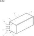
- Figure 1 shows an electrochemical energy storage device with a schematically illustrated temperature control circuit.
- the housing has an inlet 5 and an outlet 7 for a heat transfer medium.
- the heat transfer medium may flow from top to bottom as shown here or, as an alternative, from bottom to top.
- the inlet preferably is connected to a distributor by which the heat transfer medium is distributed to the heat transfer members which run parallel to the electrochemical cells in the housing 3.
- the heat transfer members are connected to a collector which is connected to the outlet 7.
- each fluid circuit comprises an inlet 5 and an outlet 7 which are connected to the heat transfer members of the respective fluid circuit.
- the heat transfer medium removed from the housing 3 via the outlet 7 is then passed through a heat exchanger 9, a heating device 11, and a delivery device 13 and is then re-introduced into the housing 3 via the inlet 5.
- the heat exchanger 9, the heating device 11 and the delivery device 13 are preferably arranged in a channel, wherein the channel can be embodied as a pipe or as a channel with any other cross section, e.g. as a rectangular channel.
- the heat exchanger 9 is used, in particular, to cool the heat transfer medium when the heat transfer medium is used to cool the electrochemical cells, as is necessary, for example, in the case of alkali metal-sulfur cells during the charging and discharging process. During this process, the heat transfer medium in the heat exchanger 9 releases heat to another heat transfer medium, wherein water or any other desired conventional heat transfer medium, e.g. a thermal oil, can be used as a heat transfer medium here, for example.
- water or any other desired conventional heat transfer medium e.g. a thermal oil
- the heating device 11 is provided.
- the heat transfer medium is heated.
- heating can be accomplished directly or indirectly, wherein indirect heating is accomplished, for example, by using a heating medium which releases heat to the heat transfer medium for controlling the temperature of the electrochemical cells.
- a heating medium which releases heat to the heat transfer medium for controlling the temperature of the electrochemical cells.
- a heating device in which the heat transfer medium is heated electrically or inductively or, alternatively, by burning a fuel.
- thermoelectric heat transfer medium can be varied, either for heating or for cooling, or a combination unit is used which cools by means of a heat transfer medium and additionally contains electric heating elements for heating, by means of which the heat transfer medium can be heated when required to control the temperature of the electrochemical cells.
- the delivery device 13 is dependent on the heat transfer medium used.
- the delivery device 13 is a pump, for example.
- the delivery device 13 is dimensioned in such a way that a quantity of heat transfer medium sufficient to control the temperature of the electrochemical cells can be passed through the heat transfer members.
- an open circuit preferably is used if the heat transfer medium is air.
- the heat transfer medium is air.
- ambient air is fed through the inlet 5 into the housing 3 and removed from the housing through the outlet 7.
- the air is blown from the outlet into the surroundings.
- the delivery device 13 particularly a blower, is connected to the inlet 5 and/or the outlet 7.
- the heating device 11 it is possible to provide the heating device 11 in the inlet to heat the air which is sucked in by the blower.
- the heater in the distributor or in the heat transfer members through which the air flows. Further, it is also possible to arrange heating devices between the electrochemical cells and the heat transfer members.
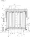
- Figures 2 and 3 show a sectional view of an electrochemical energy storage device and a plan view on the respective energy storage device having heat transfer members by which heat is transferred by heat conduction.
- the electrochemical energy storage device 1 comprises a battery pack 41 which is composed of a plurality of single electrochemical cells 15.
- the electrochemical cells 15 are placed in the housing 3, which comprises a box 43, which preferably has a rectangular parallelepiped shape and encloses the space 19 in which the electrochemical cells 15 are placed.
- the box 24 has an opening 45 which is closed by a lid 47.
- the lid 47 preferably comprises a rim 49 which extends downwards and surrounds the upper part of the box 43.
- the size of the lid 47 is such that a first duct is formed between the box 43 and the lid 47.
- the box 43 comprises a second duct 23 below the electrochemical cells 15 and heat transfer members 17, which are arranged between the electrochemical cells 15.
- the space 19 which is not filled with the electrochemical cells 15 and the heat transfer members 17 preferably is filled with a solid or liquid medium, particularly a solid particulate medium, for example sand like vermiculite or silica sand.
- the liquid or solid medium particularly is used to reduce the influence of the surroundings in the event of failure such as breakage, abnormal heating or leakage of active material in a single electrochemical cell 15.
- each electrochemical cell comprises a negative electrode terminal 51 which projects from the center of the upper end of the electrochemical cell 15 in the state mounted in the housing 3, and a positive electrode terminal 53 which projects from the peripheral edge of the electrochemical cell 15.
- a connection terminal 55 In the battery pack 41, one positive electrode terminal 53 and a negative electrode terminal 51 arranged adjacent to each other are electrically connected by a connection terminal 55, thereby forming a string in which a plurality of electrochemical cells 15 are connected in series.
- a part of the connection terminals 55 is shown in figure 3 .
- a plurality of strings are connected in parallel to form a block, and the plurality of blocks are connected in series.
- the lid 47 preferably is detachably attached to the box 43 and is placed on the box 43 when the electrochemical energy storage device 1 is used, and is removed from the box 43 when the battery pack 41 is taken in and out.
- the lid 3 preferably is composed of a metallic outer plate 65 facing the outside, a metallic inner plate 67 facing the inside, and a heat insulating material 69 being filled between the outer plate 65 and the inner plate 67.
- the heat insulating materials 63, 69 are used in an atmospheric atmosphere, and the box 43 and the lid 47 have an atmospheric heat insulating structure.
- the outer plate 59 and the inner plate 61 are provided in such a shape and arrangement that they do not contact each other via the heat insulating material 63, and the outer plate 65 and the inner plate 67 are also provided in such a shape and arrangement that they do not contact each other via the heat insulating material 69.
- a configuration is adopted in which the outer plate 59 and the inner plate 61 as well as the outer plate 65 and the inner plate 67 include a space in between, by which in addition to the thermal insulation also electrical insulation is ensured.
- a gap 71 is formed between the outer plate 59 and the inner plate 61 and a gap 73 is formed between the outer plate 65 and the inner plate 67. If air is present inside the box 43 and the lid 47 and is heated and expands during use, the air flows out to the outside through the gaps 71, 73. As a result, deformation of the box 43 and the lid 47 due to thermal expansion of air is suppressed.
- the box 43 and/or the lid 47 may have a vacuum heat insulating structure by adopting a vacuum heat insulating board as the heat insulating material 63, 69.
- a vacuum heat insulating board as the heat insulating material 63, 69.
- the inner plates 61, 67 and the outer plates 59, 65 are tightly connected.
- an insulating cushioning material 75 is disposed on the open end portion of the box 43 having the gap 71 formed therein.
- the first duct 21 is formed on the cushioning material 75 and extends between the outer plate 59 of the box 43 and the inner plate 67 of the lid 47.
- the first and second ducts 21, 23 are respectively provided with a first fan 77 and a second fan 79 which may be electric intake fans.
- the first fan 77 and the second fan 79 are provided for supplying external air to the first duct 21 and the second duct 23, respectively.
- the operation of the first and second fans 77, 79 may be controlled by a fan control unit.
- side heaters 81 may be provided on the surface of the inner plates 61 on each side of the box 43.
- a bottom heater 83 may be provided on the top surface 85 of the second duct 23.
- the upper surface of the bottom heater 83 is horizontal, and the battery pack 41 is arranged on the upper surface of the bottom heater 83. More specifically, a plate-like or sheet-like insulator 87 mode of, for example mica, is interposed between the bottom heater 83 and the battery pack 41, thereby ensuring insulation between the bottom heater 83 and the battery pack 41.
- the side heaters 81 and the bottom heater 83 preferably are electric heaters for heating the inside of the box 43.
- the side heaters 81 and the bottom heater 83 are used to maintain the inside of the box 43 at an operating temperature so as to keep the active material of each electrochemical cell 15 of the battery pack 41 in a molten state when the electrochemical energy storage device 1 is in a standby state in which the battery pack 41 is not charged or discharged.
- the operation of the side heaters 81 and the bottom heater 83 is controlled by a heater control unit.
- rod shaped heat transfer members 17 are provided for releasing heat generated in the single electrochemical cells 15 during operation to the outside of the space 19.
- the heat transfer members 17 are made of a material having high thermal conductivity, typically a metal having high thermal conductivity.
- aluminum is used as the material of the heat transfer members 17.
- aluminum, steel, copper or an alloy of some of these metals may be used.
- the heat transfer members 17 also may have any other shape, for example the shape of a rectangular column, a triangular column or even a shape with irregularities on the side surface along the longitudinal direction so as to increase the surface area, as long as the heat transfer members 17 ca be disposed in the space between the electrochemical cells 15. Further, it is also possible, that a plurality of heat transfer members 17 is arranged in each space between the electrochemical cells 15.
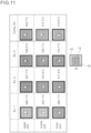
- Embodiments with heat transfer members 17 being pipes or rods are shown in figures 8 and 9 .
- the electrochemical cells 15 are arranged around the heat transfer members 17.
- the electrochemical cells 15 are arranged around the heat transfer members 17.
- the number of electrochemical cells 15 being arranged around one heat transfer member 17 particularly depends on the diameters of the heat transfer members 17 and the electrochemical cells 15. The larger the diameter of the electrochemical cells 15 and the smaller the diameter of the heat transfer members 17, the smaller is the number of electrochemical cells 15 which can be arranged around a heat transfer member 17 without forming a space which is too large for a satisfying heat transfer.
- the heat transfer members 17 penetrate into the first duct 21 and the upper end 91 is brought into contact with the upper surface of the first duct 21 as shown in figure 4 .
Landscapes
- Chemical & Material Sciences (AREA)
- Chemical Kinetics & Catalysis (AREA)
- Electrochemistry (AREA)
- General Chemical & Material Sciences (AREA)
- Engineering & Computer Science (AREA)
- Manufacturing & Machinery (AREA)
- Secondary Cells (AREA)
Applications Claiming Priority (2)
| Application Number | Priority Date | Filing Date | Title |
|---|---|---|---|
| EP21188163 | 2021-07-28 | ||
| PCT/EP2022/070909 WO2023006725A1 (en) | 2021-07-28 | 2022-07-26 | Electrochemical energy storage device |
Publications (3)
| Publication Number | Publication Date |
|---|---|
| EP4378020A1 EP4378020A1 (en) | 2024-06-05 |
| EP4378020C0 EP4378020C0 (en) | 2025-07-09 |
| EP4378020B1 true EP4378020B1 (en) | 2025-07-09 |
Family
ID=77103958
Family Applications (1)
| Application Number | Title | Priority Date | Filing Date |
|---|---|---|---|
| EP22754421.0A Active EP4378020B1 (en) | 2021-07-28 | 2022-07-26 | Electrochemical energy storage device |
Country Status (9)
| Country | Link |
|---|---|
| US (1) | US20240339690A1 (enExample) |
| EP (1) | EP4378020B1 (enExample) |
| JP (1) | JP2024527437A (enExample) |
| KR (1) | KR20240033061A (enExample) |
| CN (1) | CN117837000A (enExample) |
| AU (1) | AU2022320883A1 (enExample) |
| CA (1) | CA3227198A1 (enExample) |
| ES (1) | ES3046033T3 (enExample) |
| WO (1) | WO2023006725A1 (enExample) |
Families Citing this family (1)
| Publication number | Priority date | Publication date | Assignee | Title |
|---|---|---|---|---|
| DE102024117410A1 (de) | 2024-06-20 | 2025-12-24 | Bayerische Motoren Werke Aktiengesellschaft | Zellanordnung für eine Energiespeichervorrichtung insbesondere für ein Kraftfahrzeug, Energiespeichervorrichtung, Kraftfahrzeug |
Family Cites Families (11)
| Publication number | Priority date | Publication date | Assignee | Title |
|---|---|---|---|---|
| AU7309281A (en) | 1980-07-23 | 1982-01-28 | Chloride Silent Power Ltd. | Electrochemical storage batteries and modules therefor |
| DE4013269A1 (de) | 1990-04-26 | 1991-10-31 | Abb Patent Gmbh | Hochtemperaturspeicherbatterie |
| JP2000297989A (ja) | 1999-04-12 | 2000-10-24 | Ngk Insulators Ltd | 熱風循環式加熱炉及び、これを用いたナトリウム−硫黄単電池の検査方法 |
| US7398819B2 (en) * | 2004-11-12 | 2008-07-15 | Carrier Corporation | Minichannel heat exchanger with restrictive inserts |
| WO2008079135A1 (en) * | 2006-12-26 | 2008-07-03 | Carrier Corporation | Heat exchanger design for improved performance and manufacturability |
| JP5080829B2 (ja) | 2007-03-08 | 2012-11-21 | 日本碍子株式会社 | ナトリウム−硫黄電池用パッケージ |
| KR20120012303A (ko) * | 2010-07-30 | 2012-02-09 | 삼성전자주식회사 | 균일한 온도분포를 갖는 연료전지 스택 및 그 구동방법 |
| EP3340365B1 (en) | 2015-09-21 | 2020-04-22 | LG Chem, Ltd. | Battery module including array of cooling fins having different thicknesses |
| EP3182480A1 (de) | 2015-12-14 | 2017-06-21 | Basf Se | Vorrichtung zur speicherung elektrischer energie sowie verfahren zu deren montage und inbetriebnahme und zu deren betrieb |
| WO2019206864A1 (de) | 2018-04-27 | 2019-10-31 | Basf Se | Elektrochemischer energiespeicher |
| JP7083792B2 (ja) | 2019-09-10 | 2022-06-13 | 矢崎総業株式会社 | 車両用電池パック |
-
2022
- 2022-07-26 CN CN202280052714.XA patent/CN117837000A/zh active Pending
- 2022-07-26 EP EP22754421.0A patent/EP4378020B1/en active Active
- 2022-07-26 US US18/579,103 patent/US20240339690A1/en active Pending
- 2022-07-26 WO PCT/EP2022/070909 patent/WO2023006725A1/en not_active Ceased
- 2022-07-26 AU AU2022320883A patent/AU2022320883A1/en active Pending
- 2022-07-26 KR KR1020247005569A patent/KR20240033061A/ko active Pending
- 2022-07-26 JP JP2024505330A patent/JP2024527437A/ja active Pending
- 2022-07-26 CA CA3227198A patent/CA3227198A1/en active Pending
- 2022-07-26 ES ES22754421T patent/ES3046033T3/es active Active
Also Published As
| Publication number | Publication date |
|---|---|
| CN117837000A (zh) | 2024-04-05 |
| US20240339690A1 (en) | 2024-10-10 |
| ES3046033T3 (en) | 2025-12-01 |
| JP2024527437A (ja) | 2024-07-24 |
| AU2022320883A1 (en) | 2024-02-08 |
| EP4378020C0 (en) | 2025-07-09 |
| KR20240033061A (ko) | 2024-03-12 |
| CA3227198A1 (en) | 2023-02-02 |
| EP4378020A1 (en) | 2024-06-05 |
| WO2023006725A1 (en) | 2023-02-02 |
Similar Documents
| Publication | Publication Date | Title |
|---|---|---|
| US6146783A (en) | Multi-cell storage battery | |
| US20160365612A1 (en) | Thermal management of liquid metal batteries | |
| CN114256552A (zh) | 单体电池、动力电池包及电动车 | |
| GB2027978A (en) | A battery | |
| EP3345243B1 (en) | Energy storage device with reduced temperature variability between cells | |
| US20240339690A1 (en) | Electrochemical energy storage device | |
| EP3557689A1 (en) | Battery pack | |
| TWI866907B (zh) | 電化學能量儲存裝置 | |
| JP7607123B2 (ja) | 高温動作型の二次電池の単電池およびモジュール電池 | |
| CN116802889B (zh) | 电池、用电设备、制备电池的方法和设备 | |
| CN216872163U (zh) | 箱体、电池以及用电装置 | |
| CN110915029A (zh) | 具有减小的温度差的用于二次电池化成过程的充电/放电设备 | |
| WO2025246038A1 (zh) | 电池及用电装置 | |
| CN220324538U (zh) | 一种电池包 | |
| WO2024230138A1 (zh) | 电池和用电装置 | |
| JPH08339823A (ja) | 高温電池モジュール及びこれを用いた電池システム | |
| KR20190072489A (ko) | 젤리-롤형 전극조립체를 포함하는 다각형 기둥 전지 캔 및 이를 포함하는 전지팩 | |
| KR101640886B1 (ko) | 팩 하우징 및 이를 포함하는 배터리 팩 | |
| CN220984674U (zh) | 储能单元及储能系统 | |
| CN219873693U (zh) | 电池模组、电池包及用电装置 | |
| JPH03257766A (ja) | ナトリウム硫黄電池のモジュール | |
| JP7834247B2 (ja) | バッテリー組立体およびバッテリーパック | |
| KR102941955B1 (ko) | 배터리 모듈 냉각 장치 | |
| CN120752785A (zh) | 电池组 | |
| JP2007273297A (ja) | ナトリウム−硫黄電池 |
Legal Events
| Date | Code | Title | Description |
|---|---|---|---|
| STAA | Information on the status of an ep patent application or granted ep patent |
Free format text: STATUS: UNKNOWN |
|
| STAA | Information on the status of an ep patent application or granted ep patent |
Free format text: STATUS: THE INTERNATIONAL PUBLICATION HAS BEEN MADE |
|
| PUAI | Public reference made under article 153(3) epc to a published international application that has entered the european phase |
Free format text: ORIGINAL CODE: 0009012 |
|
| STAA | Information on the status of an ep patent application or granted ep patent |
Free format text: STATUS: REQUEST FOR EXAMINATION WAS MADE |
|
| 17P | Request for examination filed |
Effective date: 20240228 |
|
| AK | Designated contracting states |
Kind code of ref document: A1 Designated state(s): AL AT BE BG CH CY CZ DE DK EE ES FI FR GB GR HR HU IE IS IT LI LT LU LV MC MK MT NL NO PL PT RO RS SE SI SK SM TR |
|
| DAV | Request for validation of the european patent (deleted) | ||
| DAX | Request for extension of the european patent (deleted) | ||
| GRAP | Despatch of communication of intention to grant a patent |
Free format text: ORIGINAL CODE: EPIDOSNIGR1 |
|
| STAA | Information on the status of an ep patent application or granted ep patent |
Free format text: STATUS: GRANT OF PATENT IS INTENDED |
|
| INTG | Intention to grant announced |
Effective date: 20250227 |
|
| GRAS | Grant fee paid |
Free format text: ORIGINAL CODE: EPIDOSNIGR3 |
|
| GRAA | (expected) grant |
Free format text: ORIGINAL CODE: 0009210 |
|
| STAA | Information on the status of an ep patent application or granted ep patent |
Free format text: STATUS: THE PATENT HAS BEEN GRANTED |
|
| AK | Designated contracting states |
Kind code of ref document: B1 Designated state(s): AL AT BE BG CH CY CZ DE DK EE ES FI FR GB GR HR HU IE IS IT LI LT LU LV MC MK MT NL NO PL PT RO RS SE SI SK SM TR |
|
| REG | Reference to a national code |
Ref country code: GB Ref legal event code: FG4D |
|
| REG | Reference to a national code |
Ref country code: CH Ref legal event code: EP |
|
| REG | Reference to a national code |
Ref country code: IE Ref legal event code: FG4D |
|
| REG | Reference to a national code |
Ref country code: DE Ref legal event code: R096 Ref document number: 602022017388 Country of ref document: DE |
|
| U01 | Request for unitary effect filed |
Effective date: 20250804 |
|
| U07 | Unitary effect registered |
Designated state(s): AT BE BG DE DK EE FI FR IT LT LU LV MT NL PT RO SE SI Effective date: 20250902 |
|
| PGFP | Annual fee paid to national office [announced via postgrant information from national office to epo] |
Ref country code: ES Payment date: 20250812 Year of fee payment: 4 |
|
| PGFP | Annual fee paid to national office [announced via postgrant information from national office to epo] |
Ref country code: GR Payment date: 20250925 Year of fee payment: 4 |
|
| PGFP | Annual fee paid to national office [announced via postgrant information from national office to epo] |
Ref country code: TR Payment date: 20250930 Year of fee payment: 4 |
|
| PGFP | Annual fee paid to national office [announced via postgrant information from national office to epo] |
Ref country code: CH Payment date: 20250801 Year of fee payment: 4 |
|
| REG | Reference to a national code |
Ref country code: GR Ref legal event code: EP Ref document number: 20250401814 Country of ref document: GR Effective date: 20251009 |
|
| REG | Reference to a national code |
Ref country code: ES Ref legal event code: FG2A Ref document number: 3046033 Country of ref document: ES Kind code of ref document: T3 Effective date: 20251201 |
|
| PG25 | Lapsed in a contracting state [announced via postgrant information from national office to epo] |
Ref country code: IS Free format text: LAPSE BECAUSE OF FAILURE TO SUBMIT A TRANSLATION OF THE DESCRIPTION OR TO PAY THE FEE WITHIN THE PRESCRIBED TIME-LIMIT Effective date: 20251109 |
|
| PG25 | Lapsed in a contracting state [announced via postgrant information from national office to epo] |
Ref country code: NO Free format text: LAPSE BECAUSE OF FAILURE TO SUBMIT A TRANSLATION OF THE DESCRIPTION OR TO PAY THE FEE WITHIN THE PRESCRIBED TIME-LIMIT Effective date: 20251009 |
|
| PG25 | Lapsed in a contracting state [announced via postgrant information from national office to epo] |
Ref country code: HR Free format text: LAPSE BECAUSE OF FAILURE TO SUBMIT A TRANSLATION OF THE DESCRIPTION OR TO PAY THE FEE WITHIN THE PRESCRIBED TIME-LIMIT Effective date: 20250709 |
|
| U21 | Renewal fee for the european patent with unitary effect paid with additional fee |
Year of fee payment: 4 Effective date: 20251215 |
|
| PG25 | Lapsed in a contracting state [announced via postgrant information from national office to epo] |
Ref country code: PL Free format text: LAPSE BECAUSE OF FAILURE TO SUBMIT A TRANSLATION OF THE DESCRIPTION OR TO PAY THE FEE WITHIN THE PRESCRIBED TIME-LIMIT Effective date: 20250709 |
|
| PG25 | Lapsed in a contracting state [announced via postgrant information from national office to epo] |
Ref country code: RS Free format text: LAPSE BECAUSE OF FAILURE TO SUBMIT A TRANSLATION OF THE DESCRIPTION OR TO PAY THE FEE WITHIN THE PRESCRIBED TIME-LIMIT Effective date: 20251009 |
|
| PG25 | Lapsed in a contracting state [announced via postgrant information from national office to epo] |
Ref country code: SM Free format text: LAPSE BECAUSE OF FAILURE TO SUBMIT A TRANSLATION OF THE DESCRIPTION OR TO PAY THE FEE WITHIN THE PRESCRIBED TIME-LIMIT Effective date: 20250709 |
|
| PGFP | Annual fee paid to national office [announced via postgrant information from national office to epo] |
Ref country code: AT Payment date: 20260410 Year of fee payment: 4 |
|
| PG25 | Lapsed in a contracting state [announced via postgrant information from national office to epo] |
Ref country code: CZ Free format text: LAPSE BECAUSE OF FAILURE TO SUBMIT A TRANSLATION OF THE DESCRIPTION OR TO PAY THE FEE WITHIN THE PRESCRIBED TIME-LIMIT Effective date: 20250709 |
|
| PG25 | Lapsed in a contracting state [announced via postgrant information from national office to epo] |
Ref country code: SK Free format text: LAPSE BECAUSE OF FAILURE TO SUBMIT A TRANSLATION OF THE DESCRIPTION OR TO PAY THE FEE WITHIN THE PRESCRIBED TIME-LIMIT Effective date: 20250709 |
|
| PLBE | No opposition filed within time limit |
Free format text: ORIGINAL CODE: 0009261 |
|
| STAA | Information on the status of an ep patent application or granted ep patent |
Free format text: STATUS: NO OPPOSITION FILED WITHIN TIME LIMIT |