EP4375606A1 - Selbstenteisender wärmetauscher und verfahren zu dessen verwendung - Google Patents
Selbstenteisender wärmetauscher und verfahren zu dessen verwendung Download PDFInfo
- Publication number
- EP4375606A1 EP4375606A1 EP22846332.9A EP22846332A EP4375606A1 EP 4375606 A1 EP4375606 A1 EP 4375606A1 EP 22846332 A EP22846332 A EP 22846332A EP 4375606 A1 EP4375606 A1 EP 4375606A1
- Authority
- EP
- European Patent Office
- Prior art keywords
- rotor
- heat exchanger
- exhaust air
- air
- supply air
- Prior art date
- Legal status (The legal status is an assumption and is not a legal conclusion. Google has not performed a legal analysis and makes no representation as to the accuracy of the status listed.)
- Pending
Links
Images
Classifications
-
- F—MECHANICAL ENGINEERING; LIGHTING; HEATING; WEAPONS; BLASTING
- F28—HEAT EXCHANGE IN GENERAL
- F28F—DETAILS OF HEAT-EXCHANGE AND HEAT-TRANSFER APPARATUS, OF GENERAL APPLICATION
- F28F17/00—Removing ice or water from heat-exchange apparatus
-
- F—MECHANICAL ENGINEERING; LIGHTING; HEATING; WEAPONS; BLASTING
- F28—HEAT EXCHANGE IN GENERAL
- F28D—HEAT-EXCHANGE APPARATUS, NOT PROVIDED FOR IN ANOTHER SUBCLASS, IN WHICH THE HEAT-EXCHANGE MEDIA DO NOT COME INTO DIRECT CONTACT
- F28D11/00—Heat-exchange apparatus employing moving conduits
- F28D11/02—Heat-exchange apparatus employing moving conduits the movement being rotary, e.g. performed by a drum or roller
-
- F—MECHANICAL ENGINEERING; LIGHTING; HEATING; WEAPONS; BLASTING
- F28—HEAT EXCHANGE IN GENERAL
- F28D—HEAT-EXCHANGE APPARATUS, NOT PROVIDED FOR IN ANOTHER SUBCLASS, IN WHICH THE HEAT-EXCHANGE MEDIA DO NOT COME INTO DIRECT CONTACT
- F28D19/00—Regenerative heat-exchange apparatus in which the intermediate heat-transfer medium or body is moved successively into contact with each heat-exchange medium
- F28D19/04—Regenerative heat-exchange apparatus in which the intermediate heat-transfer medium or body is moved successively into contact with each heat-exchange medium using rigid bodies, e.g. mounted on a movable carrier
- F28D19/041—Regenerative heat-exchange apparatus in which the intermediate heat-transfer medium or body is moved successively into contact with each heat-exchange medium using rigid bodies, e.g. mounted on a movable carrier with axial flow through the intermediate heat-transfer medium
- F28D19/042—Rotors; Assemblies of heat absorbing masses
-
- F—MECHANICAL ENGINEERING; LIGHTING; HEATING; WEAPONS; BLASTING
- F28—HEAT EXCHANGE IN GENERAL
- F28D—HEAT-EXCHANGE APPARATUS, NOT PROVIDED FOR IN ANOTHER SUBCLASS, IN WHICH THE HEAT-EXCHANGE MEDIA DO NOT COME INTO DIRECT CONTACT
- F28D19/00—Regenerative heat-exchange apparatus in which the intermediate heat-transfer medium or body is moved successively into contact with each heat-exchange medium
- F28D19/04—Regenerative heat-exchange apparatus in which the intermediate heat-transfer medium or body is moved successively into contact with each heat-exchange medium using rigid bodies, e.g. mounted on a movable carrier
- F28D19/045—Regenerative heat-exchange apparatus in which the intermediate heat-transfer medium or body is moved successively into contact with each heat-exchange medium using rigid bodies, e.g. mounted on a movable carrier with radial flow through the intermediate heat-transfer medium
-
- F—MECHANICAL ENGINEERING; LIGHTING; HEATING; WEAPONS; BLASTING
- F28—HEAT EXCHANGE IN GENERAL
- F28D—HEAT-EXCHANGE APPARATUS, NOT PROVIDED FOR IN ANOTHER SUBCLASS, IN WHICH THE HEAT-EXCHANGE MEDIA DO NOT COME INTO DIRECT CONTACT
- F28D19/00—Regenerative heat-exchange apparatus in which the intermediate heat-transfer medium or body is moved successively into contact with each heat-exchange medium
- F28D19/04—Regenerative heat-exchange apparatus in which the intermediate heat-transfer medium or body is moved successively into contact with each heat-exchange medium using rigid bodies, e.g. mounted on a movable carrier
- F28D19/047—Sealing means
-
- F—MECHANICAL ENGINEERING; LIGHTING; HEATING; WEAPONS; BLASTING
- F28—HEAT EXCHANGE IN GENERAL
- F28D—HEAT-EXCHANGE APPARATUS, NOT PROVIDED FOR IN ANOTHER SUBCLASS, IN WHICH THE HEAT-EXCHANGE MEDIA DO NOT COME INTO DIRECT CONTACT
- F28D19/00—Regenerative heat-exchange apparatus in which the intermediate heat-transfer medium or body is moved successively into contact with each heat-exchange medium
- F28D19/04—Regenerative heat-exchange apparatus in which the intermediate heat-transfer medium or body is moved successively into contact with each heat-exchange medium using rigid bodies, e.g. mounted on a movable carrier
- F28D19/048—Bearings; Driving means
-
- F—MECHANICAL ENGINEERING; LIGHTING; HEATING; WEAPONS; BLASTING
- F28—HEAT EXCHANGE IN GENERAL
- F28F—DETAILS OF HEAT-EXCHANGE AND HEAT-TRANSFER APPARATUS, OF GENERAL APPLICATION
- F28F13/00—Arrangements for modifying heat-transfer, e.g. increasing, decreasing
- F28F13/003—Arrangements for modifying heat-transfer, e.g. increasing, decreasing by using permeable mass, perforated or porous materials
-
- F—MECHANICAL ENGINEERING; LIGHTING; HEATING; WEAPONS; BLASTING
- F28—HEAT EXCHANGE IN GENERAL
- F28F—DETAILS OF HEAT-EXCHANGE AND HEAT-TRANSFER APPARATUS, OF GENERAL APPLICATION
- F28F19/00—Preventing the formation of deposits or corrosion, e.g. by using filters or scrapers
- F28F19/006—Preventing deposits of ice
-
- F—MECHANICAL ENGINEERING; LIGHTING; HEATING; WEAPONS; BLASTING
- F28—HEAT EXCHANGE IN GENERAL
- F28F—DETAILS OF HEAT-EXCHANGE AND HEAT-TRANSFER APPARATUS, OF GENERAL APPLICATION
- F28F27/00—Control arrangements or safety devices specially adapted for heat-exchange or heat-transfer apparatus
- F28F27/006—Control arrangements or safety devices specially adapted for heat-exchange or heat-transfer apparatus specially adapted for regenerative heat-exchange apparatus
-
- Y—GENERAL TAGGING OF NEW TECHNOLOGICAL DEVELOPMENTS; GENERAL TAGGING OF CROSS-SECTIONAL TECHNOLOGIES SPANNING OVER SEVERAL SECTIONS OF THE IPC; TECHNICAL SUBJECTS COVERED BY FORMER USPC CROSS-REFERENCE ART COLLECTIONS [XRACs] AND DIGESTS
- Y02—TECHNOLOGIES OR APPLICATIONS FOR MITIGATION OR ADAPTATION AGAINST CLIMATE CHANGE
- Y02B—CLIMATE CHANGE MITIGATION TECHNOLOGIES RELATED TO BUILDINGS, e.g. HOUSING, HOUSE APPLIANCES OR RELATED END-USER APPLICATIONS
- Y02B30/00—Energy efficient heating, ventilation or air conditioning [HVAC]
- Y02B30/56—Heat recovery units
Definitions
- the self-defrosting heat exchangers and their application technique are the subject of the current invention.
- the proposed heat exchanger has high efficiency and remains operational at almost any climatic level of negative temperatures and any indoor humidity.
- the heat exchanger is intended for use in supply and exhaust ventilation systems and does not mix exhaust and supply air.
- the invention relates to the field of supply and exhaust ventilation systems for premises.
- a heat exchanger is proposed for such systems, in which the heated air removed from the room transfers the majority of its heat to the cold supply air entering from the street, allowing for savings on heating.
- recuperative heat exchangers are the two types of heat exchangers used for such tasks.
- heat exchange between gases occurs continuously, either directly through the wall separating them or via an intermediate heat carrier.
- Heat exchange in regenerative heat exchangers occurs through the alternating contact of gases of varying temperatures from indoor and outdoor sources with the same heat exchanger surfaces.
- the most common heat exchangers for use in supply and exhaust ventilation of premises are plate, with intermediate heat carrier, rotor and chamber. Plate heat exchangers with an intermediate heat carrier are classified as recuperative, whereas rotary and chamber heat exchangers are classified as regenerative.
- the second disadvantage is that while the supply air is turned off, fresh air does not enter the room in an organized manner, but through cracks and other leaks. This causes overcooling of leaky partitions and subsequent freezing, which can even result in partial destruction (sprinkling of thermal insulation, peeling of coatings, etc.).
- the second disadvantage of this method is that it involves only partial defrosting of the heat exchanger.
- part of the heat exchanger functions poorly until completely defrosted, and in sections that are defrosting, the heat of the exhaust air is used ineffectively, resulting in a decrease in the heat exchanger's total efficiency.
- the first disadvantage of the method described in article [2] is that it proposes reducing the number of rotor revolutions along with heating the outside air and/or heating the exhaust air. Heating and/or heating require a large amount of energy, which significantly reduces the method's efficiency.
- the bypass is turned off, and the heat exchanger returns to normal operation (i.e., heat/energy recovery).
- an additional air heater and humidifier
- the first disadvantage of this method is the additional energy required to heat cold air to a temperature above 0°C.
- Another disadvantage is that during defrosting the normal heat exchange between incoming and exhaust air is interrupted.
- the patent RU2658265C2 (published on June 19, 2018 ; IPC: F24F 12/00) is a close analogue to the present invention. It describes a heat recuperator with a closed housing and a rotor installed inside it. The rotor's plates alternately find themselves in the warm air exiting the room and the cold air entering it. The rotor's plates are made in a form of disks mounted with a gap between them on a shaft that is oriented horizontally, perpendicular to the horizontal air flow. From time to time, it reverses the direction of movement from the room to the outside area or the outside area to the room.
- the first disadvantage of this heat exchanger is that it uses two recuperators to defrost ice (for defrosting) -one in the "exhaust" mode and the other in the "pressure” mode-and after a certain amount of time, they switch modes. This significantly increases both the dimensions of the system and its cost. Partial mixing of exhaust and supply air occurs at the moment of switching the direction of flows.
- the objective of the present invention is to create and develop a heat exchanger and a method of its use that ensures self-defrosting of the heat exchanger, that is, ensuring the melting of formed ice, during its operation in any climatic conditions while maintaining continuous operation and high heat transfer efficiency.
- the technical result is achieved by the heat exchanger with a non-vertical axis of rotation placed in a housing.
- the rotor is made up of ring elements, with the gaps between them sealed alternately along the inner and outer perimeters, forming channels that separate the supply and exhaust air.
- the housing consists of an outer and an inner cylinder.
- the outer cylinder encloses the rotor and has at least one opening in the lower part for adding exhaust air to the rotor and at least one opening in the upper part for removing exhaust air from the rotor.
- the inner cylinder is inserted into the rotor and has at least one opening in the upper part for adding supply air to the rotor and at least one opening in the lower part for removing supply air from the rotor. Additionally, the inner cylinder has a partition built into it that separates the input and output of supply air. The input and output of supply air are discharged into the inner cylinder through its ends.
- Heat exchange between the supply and exhaust air occurs through the walls of the separating channels without mixing these flows.
- the specified arrangement of openings for the input and output of supply and exhaust air into the rotor provides a generally countercurrent pattern of movement of these flows in the rotor channels, which significantly increases the efficiency of heat exchange between these flows.
- the maximum channel surface temperature will be in the lower sector of the rotor, and the minimum - in the upper sector.
- the slow rotation of the rotor causes its sectors to gradually move from the negative temperature zone, where its surfaces freeze on the exhaust air side, to the positive temperature zone, where frozen surfaces thaw and liquid condensate is discharged, and back.
- Too low rotor speed will lead to a significant increase in the thickness of the ice that builds up in the sector with a negative temperature, which significantly worsens the heat exchange between the channels for exhaust and supply air. If the rotor rotation speed is too high, incomplete thawing of the ice in the sector with a positive temperature is possible, and the contribution of the rotor's heat capacity becomes significant, reducing temperature gradients between the rotor walls and air flows and, as a result, reducing heat exchanger efficiency.
- the optimal rotor speed depends on the gap in the channels, the surface area of the channels, the flow rate and humidity of the exhaust air. In order of magnitude, this speed is about one revolution per hour and can vary several times in one direction or the other.
- the rotor 1 rotation can be not only continuous but also with stops, i.e., with a turn at a certain small angle about units of degrees, followed by a stop for less than a minute, as long as the average rotation speed is maintained.
- the intermittent rotation of the rotor i.e., with stops, enables the use of mechanisms with a lower reduction coefficient, which are correspondingly cheaper.
- Liquid condensate produced by air cooling and/or ice thawing can be discharged by gravity through a pipe in the lower part of the heat exchanger and collected under the influence of gravity.
- the annular elements forming the rotor channels can be made entirely or contain inserts made of gas-tight vapor-moisture-permeable material, allowing liquid condensate to be absorbed from the channels where it is formed and evaporated in other channels.
- the rotor To facilitate the rotation of the rotor, it can be installed with a small gap relative to the housing on rotational units, for example, rolling rollers. Also, making the heat exchanger with gaps between the rotor and the housing significantly reduces the requirements for the manufacturing accuracy of these units, but leads to unwanted flows of exhaust and supply air with the environment. To seal the gaps between the rotor and the housing, sliding seals made of brushes, felt, rubber, and so on can be used.
- the housing and ends of the rotor can be covered with thermal insulation.
- the technical result is achieved by using a heat exchanger containing a rotating rotor, through which exhaust air is introduced into the rotor through the heat exchanger opening for introducing exhaust air, supply air is introduced into the rotor through the heat exchanger opening for supply air, and exhaust air is passed through the rotor through channels for exhaust air, then supply air is passed through the rotor through the channels for supply air, exhaust air is discharged from the rotor through the heat exchanger opening to discharge the exhaust air, the supply air is discharged from the rotor through the heat exchanger opening to discharge the supply air.
- supply air is introduced and exhaust air is discharged on one side relative to the rotor's axis of rotation, and supply air is discharged and exhaust air is introduced on the other side relative to the rotor's axis of rotation.
- the rotor rotates at a speed that prevents excessive freezing of the rotor in the cold sector of the rotor, complete thawing of ice occurs in the warm sector of the rotor, and at the same time the influence of the rotor's own heat capacity on the heat exchange process between the supply and exhaust air remains insignificant. This ensures self-defrosting of the heat exchanger during its operation, high efficiency and operability in any climatic conditions.
- Heat exchange between the supply and exhaust air occurs through the walls separating the channels, without mixing these flows.
- the indicated points of entry into and exit from the rotor of supply and exhaust air provide a generally countercurrent pattern of movement of these flows in the rotor channels, which significantly increases the efficiency of heat exchange between these flows.
- the maximum surface temperature of the rotor channels will be in the sector of the exhaust air input and, consequently, the supply air outlet, and the minimum in the sector of the exhaust air outlet and the supply air input.
- the slow rotation of the rotor causes its sectors to gradually move from the negative temperature zone, where its surfaces freeze on the exhaust air side, to the positive temperature zone, where frozen surfaces thaw and liquid condensate is discharged, and back.
- Too low rotor speed will lead to a significant increase in the thickness of the ice that builds up in the sector with a negative temperature, which significantly worsens the heat exchange between the channels for exhaust and supply air. If the rotor rotation speed is too high, incomplete thawing of the ice in the sector with a positive temperature is possible, and the contribution of the rotor's heat capacity becomes significant, reducing temperature gradients between the rotor walls and air flows and, as a result, reducing heat exchanger efficiency.
- the optimal rotor speed depends on the gap in the channels, the surface area of the channels, the flow rate and humidity of the exhaust air. In order of magnitude, this speed is about one revolution per hour and can vary several times in one direction or the other.
- the rotor 1 rotation can be not only continuous but also with stops, i.e., with a turn at a certain small angle about units of degrees, followed by a stop for less than a minute, as long as the average rotation speed is maintained.
- the intermittent rotation of the rotor i.e., with stops, enables the use of mechanisms with a lower reduction coefficient, which are correspondingly cheaper.
- Liquid condensate formed as a result of air cooling and/or ice thawing can be discharged by gravity from the bottom of the heat exchanger, where it will be collected under the influence of gravity.
- Liquid condensate can be absorbed from the rotor channels, where it is formed, and evaporate in other rotor channels, provided that gas-tight, vapor-moisture-permeable materials are used in the manufacture of these channels.
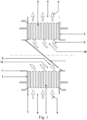
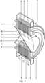
- FIGS 1 and 2 show a schematic view of the heat exchanger in a cross section and in a cross-section with a side view, respectively.
- Rotor 1 is made of ring elements, the gaps between which are sealed alternately along the inner and outer perimeter. This creates channels 2 and 3 , separating the exhaust air 4 and the supply air 5.
- the inner part of the housing 7 which is a cylinder made with slots forming openings for the input 10 and output 11 of supply air 5 .
- Also in the cylinder 7 there is a partition 12 installed separating the input 10 and the output 11 of the supply air 5 , while the input and output of the supply air into the inner part of the housing is carried out through its ends.
- Rotation of the rotor 1 can be carried out continuously at a speed of about one revolution per hour. Also, the rotation of the rotor 1 can be carried out with stops, with a rotation of a few degrees and with a stop for a time of no more than a minute so that the average speed of the rotor 1 is about one revolution per hour.
- the rotation of the rotor 1 itself can be carried out using an electric drive with reduction mechanisms using belt, chain, worm, gear and other mechanisms.
- Rotor 1's axis of rotation can be horizontal or at an angle, but it must be different from the vertical.
- the cylinders that make up the heat exchanger housing 7 can additionally be covered by rotational units 6, making it easier to rotate the rotor 1 relative to the housing 7.
- rotational units 6, rolling rollers and other similar units can be used, capable of positioning the position of the rotor 1 relative to the housing and at the same time facilitating the rotation of the rotor 1 .
- Heat exchange between the supply air 5 and the exhaust air 4 occurs through the walls separating the channels without mixing these flows.
- the specified arrangement of openings for the input 8 , 10 into the rotor 1 and the output 9 , 11 from the rotor 1 of the supply air 5 and exhaust air 4 provides a generally countercurrent pattern of movement of these flows in the channels of the rotor 1 , which significantly increases the efficiency of heat exchange between these flows.
- the maximum surface temperature of the channels will be in the lower sector of the rotor 1 , and the minimum - in the upper sector.
- the slow rotation of the rotor 1 causes its sectors to gradually move from the negative temperature zone, where its surfaces freeze on the exhaust air 4 side, positive temperature zone, where frozen surfaces thaw and liquid condensate is discharged, and back.
- continuous defrosting of the rotor1 occurs.
- Too low rotor 1 speed will lead to a significant increase in the thickness of the ice that builds up in the sector with a negative temperature, which significantly worsens the heat exchange between the channels for exhaust air 4 and the supply air 5 .
- the rotor 1 rotation can be not only continuous, but also with stops, i.e. with a turn at a certain small angle about units of degrees, followed by a stop for less than a minute, as long as the average rotation speed is maintained.
- the intermittent rotation of the rotor 1, i.e., with stops, enables the use of mechanisms with a lower reduction coefficient, which are correspondingly cheaper.
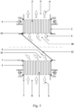
- the heat exchanger can be additionally equipped with sliding sealing elements 13 , the placement of which is shown in Figure 3 .
- Sliding sealing elements 13 are located between the housing 7 and the rotor 1 .
- the additional use of sealing elements 13 makes it possible to seal the gaps between the rotor 1 and the housing 7 so as to eliminate unwanted flows of exhaust and supply air with the environment and with each other.
- sliding seals made of brushes, felt, rubber, etc. can be used.
- the annular elements forming channels 2 and 3 of the rotor 1 can be made entirely or contain inserts made of gas-tight vapor-moisture-permeable material, allowing liquid condensate to be absorbed from the channels where it is formed and evaporated in other channels.
- Liquid condensate can also be discharged by draining it under the influence of gravity.
- the heat exchanger housing 7 may additionally have openings for draining liquid condensate.
- the housing 7 and the ends of the rotor 1 can be additionally covered with thermal insulation.
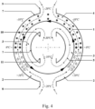
- the heat exchanger operates as follows, according to the application method of the heat exchanger, the circuit diagram of which is shown in Figure 4 .
- the situation with ventilation of a warm room (+20°C) with a humidity of about 55% (absolute moisture content 9.4 g/m 3 ) in conditions of significant negative external temperatures (-30°C) is described.
- the flow rates of exhaust and supply air are balanced, i.e. approximately equal.
- the exhaust air 4 enters the rotor 1 through the input 8 and, moving through the channels 2 on both sides of the rotor's 1 axis of rotation to the output 9 , gives up its heat to the supply air 5 , moving towards it also on both sides of the rotor's 1 axis of rotation through other channels 3 from input 10 to output 11 .
- the exhaust air 4 cools down, and the supply air 5 heats up. Heat exchange between the flows 4 and 5 is carried out through the surfaces of the separating channels 2 and 3 .
- the rotor 1 causes the zone of intensive freezing of the channel surfaces 2 to gradually shift. On the one hand, it enters a zone of deep negative temperatures, where the freezing rate decreases significantly; on the other hand, it moves into a zone of positive temperatures, where it thaws.
- the maximum thickness of ice formation can be controlled by varying the rotation speed of the rotor 1and the surface area of its channels 2 in relation to the volume of exhaust air 4.
- the initial humidity of the exhaust air has no effect on the amount of ice. Because the moisture content of air at temperatures below -20°C (about 1 g/m 3 ) is so low, lowering the temperature does not significantly increase ice growth. As a result, the proposed device can operate at significantly lower external temperatures.
- the discharge of liquid condensate from channels 2 of the exhaust air 4 is possible in different ways. For example, by gravity-driven draining through a pipe in the lower part of the heat exchanger (not shown in the figure) or by absorption on the channel 2 surface followed by evaporation in channel 3, by the production of ring elements that either entirely or partially contain gas-dense, vapor and moisture-resistant inserts.
- the rotor 1 during operation of the rotor 1 , its operating speed can be additionally manually or automatically adjusted. This is carried out in accordance with air parameters, including indoor and outdoor air temperatures, indoor and outdoor humidity levels, and so forth. Adjusting the speed based on the air parameters enables to use the heat exchanger more efficiently under any external conditions.
- air parameters including indoor and outdoor air temperatures, indoor and outdoor humidity levels, and so forth. Adjusting the speed based on the air parameters enables to use the heat exchanger more efficiently under any external conditions.
Landscapes
- Engineering & Computer Science (AREA)
- Physics & Mathematics (AREA)
- Thermal Sciences (AREA)
- Mechanical Engineering (AREA)
- General Engineering & Computer Science (AREA)
- Chemical & Material Sciences (AREA)
- Dispersion Chemistry (AREA)
- Heat-Exchange Devices With Radiators And Conduit Assemblies (AREA)
- Defrosting Systems (AREA)
Applications Claiming Priority (2)
| Application Number | Priority Date | Filing Date | Title |
|---|---|---|---|
| RU2021121518A RU2774936C1 (ru) | 2021-07-20 | Саморазмораживающийся теплообменник для вентиляции | |
| PCT/RU2022/050179 WO2023003496A1 (ru) | 2021-07-20 | 2022-06-08 | Саморазмораживающийся теплообменник и способ его применения |
Publications (2)
| Publication Number | Publication Date |
|---|---|
| EP4375606A1 true EP4375606A1 (de) | 2024-05-29 |
| EP4375606A4 EP4375606A4 (de) | 2025-08-20 |
Family
ID=84980480
Family Applications (1)
| Application Number | Title | Priority Date | Filing Date |
|---|---|---|---|
| EP22846332.9A Pending EP4375606A4 (de) | 2021-07-20 | 2022-06-08 | Selbstenteisender wärmetauscher und verfahren zu dessen verwendung |
Country Status (5)
| Country | Link |
|---|---|
| US (1) | US20250102248A1 (de) |
| EP (1) | EP4375606A4 (de) |
| CN (1) | CN117916546A (de) |
| CA (1) | CA3231511A1 (de) |
| WO (1) | WO2023003496A1 (de) |
Family Cites Families (13)
| Publication number | Priority date | Publication date | Assignee | Title |
|---|---|---|---|---|
| US2932492A (en) * | 1955-04-21 | 1960-04-12 | Bmw Triebwerkbau Ges Mit Besch | Regenerative heat exchanger with moveable matrix |
| US3229752A (en) * | 1961-11-16 | 1966-01-18 | Svenska Rotor Maskiner Ab | Counter flow regenerative heat exchanger |
| DE1883925U (de) * | 1963-10-16 | 1963-12-05 | Appbau Rothemuehle Brandt & Kr | Regenerativ-lufterhitzer mit stationaerer regenerativ-kammer und rotierenden luftanschlusskanaelen fuer parallel geschaltete luftstroeme verschiedener pressung. |
| CN1033831C (zh) * | 1990-06-16 | 1997-01-15 | 陈佳洱 | 动力惯性驱动热交换器 |
| RU2094726C1 (ru) * | 1994-11-04 | 1997-10-27 | Опытное конструкторское бюро машиностроения | Пластинчатый теплообменник |
| JP3756735B2 (ja) * | 2000-07-21 | 2006-03-15 | 東京エレクトロン株式会社 | 処理液の温度制御方法及びその装置 |
| JP3452059B1 (ja) * | 2002-05-15 | 2003-09-29 | 松下電器産業株式会社 | 冷却装置とそれを備えた電子機器 |
| DE10327078A1 (de) * | 2003-06-13 | 2004-12-30 | Klingenburg Gmbh | Rotationswärmeaustauscher und Verfahren zur Abdichtung eines solchen |
| CN100425934C (zh) * | 2004-12-30 | 2008-10-15 | 富准精密工业(深圳)有限公司 | 转轮式全热交换装置 |
| KR20130022399A (ko) * | 2012-12-26 | 2013-03-06 | 석 규 이 | 소음이 없는 홴이 구비된 폐열회수 환기장치 |
| RU2658265C2 (ru) | 2016-08-23 | 2018-06-19 | Федеральное государственное бюджетное образовательное учреждение высшего образования "Оренбургский государственный аграрный университет" | Рекуператор тепла |
| RU2672957C1 (ru) * | 2018-06-19 | 2018-11-21 | Дмитрий Викторович Коновалов | Способ вентиляции и кондиционирования воздуха |
| RU2714133C1 (ru) * | 2019-08-02 | 2020-02-13 | федеральное государственное бюджетное образовательное учреждение высшего образования "Донской государственный технический университет", (ДГТУ) | Цилиндрический рекуперативный теплообменный аппарат коаксиального типа |
-
2022
- 2022-06-08 CA CA3231511A patent/CA3231511A1/en active Pending
- 2022-06-08 EP EP22846332.9A patent/EP4375606A4/de active Pending
- 2022-06-08 US US18/290,978 patent/US20250102248A1/en active Pending
- 2022-06-08 CN CN202280059710.4A patent/CN117916546A/zh active Pending
- 2022-06-08 WO PCT/RU2022/050179 patent/WO2023003496A1/ru not_active Ceased
Also Published As
| Publication number | Publication date |
|---|---|
| EP4375606A4 (de) | 2025-08-20 |
| WO2023003496A1 (ru) | 2023-01-26 |
| CN117916546A (zh) | 2024-04-19 |
| CA3231511A1 (en) | 2023-01-26 |
| US20250102248A1 (en) | 2025-03-27 |
Similar Documents
| Publication | Publication Date | Title |
|---|---|---|
| US7231967B2 (en) | Ventilator system and method | |
| US7819943B2 (en) | Method for dehumidifying room air | |
| US6209622B1 (en) | Ventilation system | |
| US20080000630A1 (en) | Ventilator system and method | |
| CN100346109C (zh) | 换气装置和空气调节装置 | |
| WO2010002957A2 (en) | Energy recovery ventilator | |
| FI114942B (fi) | Ilmastointilaite | |
| EP1485657B1 (de) | Wärmerekuperator mit frostschutz | |
| EP4375606A1 (de) | Selbstenteisender wärmetauscher und verfahren zu dessen verwendung | |
| Holmberg | Prediction of condensation and frosting limits in rotary wheels for heat recovery in buildings. | |
| KR100835120B1 (ko) | 현열교환기를 구비하는 통신기지국의 복합냉방장치와 그제어방법 | |
| RU2774936C1 (ru) | Саморазмораживающийся теплообменник для вентиляции | |
| JP7741806B2 (ja) | 換気装置 | |
| WO1997003324A1 (en) | Air ventilation system with rotating heat/energy recovery core | |
| JPH0334584Y2 (de) | ||
| KR100426352B1 (ko) | 에너지회수용 일체형 냉난방장치 | |
| EP1148303A2 (de) | Verfahren und Einrichtung für lokales Heizen mit regenerativer Wärmerückgewinnung | |
| CN120292835B (zh) | 一种空气源热泵除湿烘干装置及方法 | |
| CN204063315U (zh) | 窗式空调器 | |
| KR101162735B1 (ko) | 로타리형 열교환유니트와 히트펌프를 구비한 공기조화기 | |
| SU1322023A1 (ru) | Устройство дл утилизации тепловой энергии | |
| CN110260422A (zh) | 四风口新风热泵除湿机装置 | |
| CN121383544A (zh) | 冷藏设备及其除霜控制方法 | |
| CN208382969U (zh) | 油田注汽锅炉干空气能与水相热交换降温系统 | |
| FI115319B (fi) | Ilman vaihto-, kuivaus- ja lämmön talteenottolaite |
Legal Events
| Date | Code | Title | Description |
|---|---|---|---|
| STAA | Information on the status of an ep patent application or granted ep patent |
Free format text: STATUS: THE INTERNATIONAL PUBLICATION HAS BEEN MADE |
|
| PUAI | Public reference made under article 153(3) epc to a published international application that has entered the european phase |
Free format text: ORIGINAL CODE: 0009012 |
|
| STAA | Information on the status of an ep patent application or granted ep patent |
Free format text: STATUS: REQUEST FOR EXAMINATION WAS MADE |
|
| 17P | Request for examination filed |
Effective date: 20240220 |
|
| AK | Designated contracting states |
Kind code of ref document: A1 Designated state(s): AL AT BE BG CH CY CZ DE DK EE ES FI FR GB GR HR HU IE IS IT LI LT LU LV MC MK MT NL NO PL PT RO RS SE SI SK SM TR |
|
| DAV | Request for validation of the european patent (deleted) | ||
| DAX | Request for extension of the european patent (deleted) | ||
| A4 | Supplementary search report drawn up and despatched |
Effective date: 20250721 |
|
| RIC1 | Information provided on ipc code assigned before grant |
Ipc: F28D 11/02 20060101AFI20250715BHEP Ipc: F28F 17/00 20060101ALI20250715BHEP Ipc: F28D 19/00 20060101ALI20250715BHEP Ipc: F28D 19/04 20060101ALI20250715BHEP Ipc: F28F 19/00 20060101ALI20250715BHEP Ipc: F28F 13/00 20060101ALI20250715BHEP Ipc: F28F 27/00 20060101ALI20250715BHEP |