EP4375602B1 - Verfahren und vorrichtung zur verflüssigung und gegebenenfalls trennung von co2 durch destillation - Google Patents
Verfahren und vorrichtung zur verflüssigung und gegebenenfalls trennung von co2 durch destillation Download PDFInfo
- Publication number
- EP4375602B1 EP4375602B1 EP23211892.7A EP23211892A EP4375602B1 EP 4375602 B1 EP4375602 B1 EP 4375602B1 EP 23211892 A EP23211892 A EP 23211892A EP 4375602 B1 EP4375602 B1 EP 4375602B1
- Authority
- EP
- European Patent Office
- Prior art keywords
- temperature
- pressure
- flow
- feed
- feed flow
- Prior art date
- Legal status (The legal status is an assumption and is not a legal conclusion. Google has not performed a legal analysis and makes no representation as to the accuracy of the status listed.)
- Active
Links
Images
Classifications
-
- F—MECHANICAL ENGINEERING; LIGHTING; HEATING; WEAPONS; BLASTING
- F25—REFRIGERATION OR COOLING; COMBINED HEATING AND REFRIGERATION SYSTEMS; HEAT PUMP SYSTEMS; MANUFACTURE OR STORAGE OF ICE; LIQUEFACTION SOLIDIFICATION OF GASES
- F25J—LIQUEFACTION, SOLIDIFICATION OR SEPARATION OF GASES OR GASEOUS OR LIQUEFIED GASEOUS MIXTURES BY PRESSURE AND COLD TREATMENT OR BY BRINGING THEM INTO THE SUPERCRITICAL STATE
- F25J1/00—Processes or apparatus for liquefying or solidifying gases or gaseous mixtures
- F25J1/0002—Processes or apparatus for liquefying or solidifying gases or gaseous mixtures characterised by the fluid to be liquefied
- F25J1/0027—Oxides of carbon, e.g. CO2
-
- F—MECHANICAL ENGINEERING; LIGHTING; HEATING; WEAPONS; BLASTING
- F25—REFRIGERATION OR COOLING; COMBINED HEATING AND REFRIGERATION SYSTEMS; HEAT PUMP SYSTEMS; MANUFACTURE OR STORAGE OF ICE; LIQUEFACTION SOLIDIFICATION OF GASES
- F25J—LIQUEFACTION, SOLIDIFICATION OR SEPARATION OF GASES OR GASEOUS OR LIQUEFIED GASEOUS MIXTURES BY PRESSURE AND COLD TREATMENT OR BY BRINGING THEM INTO THE SUPERCRITICAL STATE
- F25J1/00—Processes or apparatus for liquefying or solidifying gases or gaseous mixtures
- F25J1/003—Processes or apparatus for liquefying or solidifying gases or gaseous mixtures characterised by the kind of cold generation within the liquefaction unit for compensating heat leaks and liquid production
- F25J1/0032—Processes or apparatus for liquefying or solidifying gases or gaseous mixtures characterised by the kind of cold generation within the liquefaction unit for compensating heat leaks and liquid production using the feed stream itself or separated fractions from it, i.e. "internal refrigeration"
- F25J1/0045—Processes or apparatus for liquefying or solidifying gases or gaseous mixtures characterised by the kind of cold generation within the liquefaction unit for compensating heat leaks and liquid production using the feed stream itself or separated fractions from it, i.e. "internal refrigeration" by vaporising a liquid return stream
-
- F—MECHANICAL ENGINEERING; LIGHTING; HEATING; WEAPONS; BLASTING
- F25—REFRIGERATION OR COOLING; COMBINED HEATING AND REFRIGERATION SYSTEMS; HEAT PUMP SYSTEMS; MANUFACTURE OR STORAGE OF ICE; LIQUEFACTION SOLIDIFICATION OF GASES
- F25J—LIQUEFACTION, SOLIDIFICATION OR SEPARATION OF GASES OR GASEOUS OR LIQUEFIED GASEOUS MIXTURES BY PRESSURE AND COLD TREATMENT OR BY BRINGING THEM INTO THE SUPERCRITICAL STATE
- F25J1/00—Processes or apparatus for liquefying or solidifying gases or gaseous mixtures
- F25J1/02—Processes or apparatus for liquefying or solidifying gases or gaseous mixtures requiring the use of refrigeration, e.g. of helium or hydrogen ; Details and kind of the refrigeration system used; Integration with other units or processes; Controlling aspects of the process
- F25J1/0201—Processes or apparatus for liquefying or solidifying gases or gaseous mixtures requiring the use of refrigeration, e.g. of helium or hydrogen ; Details and kind of the refrigeration system used; Integration with other units or processes; Controlling aspects of the process using only internal refrigeration means, i.e. without external refrigeration
- F25J1/0202—Processes or apparatus for liquefying or solidifying gases or gaseous mixtures requiring the use of refrigeration, e.g. of helium or hydrogen ; Details and kind of the refrigeration system used; Integration with other units or processes; Controlling aspects of the process using only internal refrigeration means, i.e. without external refrigeration in a quasi-closed internal refrigeration loop
-
- F—MECHANICAL ENGINEERING; LIGHTING; HEATING; WEAPONS; BLASTING
- F25—REFRIGERATION OR COOLING; COMBINED HEATING AND REFRIGERATION SYSTEMS; HEAT PUMP SYSTEMS; MANUFACTURE OR STORAGE OF ICE; LIQUEFACTION SOLIDIFICATION OF GASES
- F25J—LIQUEFACTION, SOLIDIFICATION OR SEPARATION OF GASES OR GASEOUS OR LIQUEFIED GASEOUS MIXTURES BY PRESSURE AND COLD TREATMENT OR BY BRINGING THEM INTO THE SUPERCRITICAL STATE
- F25J1/00—Processes or apparatus for liquefying or solidifying gases or gaseous mixtures
- F25J1/02—Processes or apparatus for liquefying or solidifying gases or gaseous mixtures requiring the use of refrigeration, e.g. of helium or hydrogen ; Details and kind of the refrigeration system used; Integration with other units or processes; Controlling aspects of the process
- F25J1/0228—Coupling of the liquefaction unit to other units or processes, so-called integrated processes
- F25J1/0235—Heat exchange integration
- F25J1/0242—Waste heat recovery, e.g. from heat of compression
-
- F—MECHANICAL ENGINEERING; LIGHTING; HEATING; WEAPONS; BLASTING
- F25—REFRIGERATION OR COOLING; COMBINED HEATING AND REFRIGERATION SYSTEMS; HEAT PUMP SYSTEMS; MANUFACTURE OR STORAGE OF ICE; LIQUEFACTION SOLIDIFICATION OF GASES
- F25J—LIQUEFACTION, SOLIDIFICATION OR SEPARATION OF GASES OR GASEOUS OR LIQUEFIED GASEOUS MIXTURES BY PRESSURE AND COLD TREATMENT OR BY BRINGING THEM INTO THE SUPERCRITICAL STATE
- F25J1/00—Processes or apparatus for liquefying or solidifying gases or gaseous mixtures
- F25J1/02—Processes or apparatus for liquefying or solidifying gases or gaseous mixtures requiring the use of refrigeration, e.g. of helium or hydrogen ; Details and kind of the refrigeration system used; Integration with other units or processes; Controlling aspects of the process
- F25J1/0243—Start-up or control of the process; Details of the apparatus used; Details of the refrigerant compression system used
- F25J1/0279—Compression of refrigerant or internal recycle fluid, e.g. kind of compressor, accumulator, suction drum etc.
- F25J1/0296—Removal of the heat of compression, e.g. within an inter- or afterstage-cooler against an ambient heat sink
-
- F—MECHANICAL ENGINEERING; LIGHTING; HEATING; WEAPONS; BLASTING
- F25—REFRIGERATION OR COOLING; COMBINED HEATING AND REFRIGERATION SYSTEMS; HEAT PUMP SYSTEMS; MANUFACTURE OR STORAGE OF ICE; LIQUEFACTION SOLIDIFICATION OF GASES
- F25J—LIQUEFACTION, SOLIDIFICATION OR SEPARATION OF GASES OR GASEOUS OR LIQUEFIED GASEOUS MIXTURES BY PRESSURE AND COLD TREATMENT OR BY BRINGING THEM INTO THE SUPERCRITICAL STATE
- F25J3/00—Processes or apparatus for separating the constituents of gaseous or liquefied gaseous mixtures involving the use of liquefaction or solidification
- F25J3/02—Processes or apparatus for separating the constituents of gaseous or liquefied gaseous mixtures involving the use of liquefaction or solidification by rectification, i.e. by continuous interchange of heat and material between a vapour stream and a liquid stream
- F25J3/0228—Processes or apparatus for separating the constituents of gaseous or liquefied gaseous mixtures involving the use of liquefaction or solidification by rectification, i.e. by continuous interchange of heat and material between a vapour stream and a liquid stream characterised by the separated product stream
- F25J3/0266—Processes or apparatus for separating the constituents of gaseous or liquefied gaseous mixtures involving the use of liquefaction or solidification by rectification, i.e. by continuous interchange of heat and material between a vapour stream and a liquid stream characterised by the separated product stream separation of carbon dioxide
-
- F—MECHANICAL ENGINEERING; LIGHTING; HEATING; WEAPONS; BLASTING
- F25—REFRIGERATION OR COOLING; COMBINED HEATING AND REFRIGERATION SYSTEMS; HEAT PUMP SYSTEMS; MANUFACTURE OR STORAGE OF ICE; LIQUEFACTION SOLIDIFICATION OF GASES
- F25J—LIQUEFACTION, SOLIDIFICATION OR SEPARATION OF GASES OR GASEOUS OR LIQUEFIED GASEOUS MIXTURES BY PRESSURE AND COLD TREATMENT OR BY BRINGING THEM INTO THE SUPERCRITICAL STATE
- F25J2205/00—Processes or apparatus using other separation and/or other processing means
- F25J2205/02—Processes or apparatus using other separation and/or other processing means using simple phase separation in a vessel or drum
- F25J2205/04—Processes or apparatus using other separation and/or other processing means using simple phase separation in a vessel or drum in the feed line, i.e. upstream of the fractionation step
-
- F—MECHANICAL ENGINEERING; LIGHTING; HEATING; WEAPONS; BLASTING
- F25—REFRIGERATION OR COOLING; COMBINED HEATING AND REFRIGERATION SYSTEMS; HEAT PUMP SYSTEMS; MANUFACTURE OR STORAGE OF ICE; LIQUEFACTION SOLIDIFICATION OF GASES
- F25J—LIQUEFACTION, SOLIDIFICATION OR SEPARATION OF GASES OR GASEOUS OR LIQUEFIED GASEOUS MIXTURES BY PRESSURE AND COLD TREATMENT OR BY BRINGING THEM INTO THE SUPERCRITICAL STATE
- F25J2215/00—Processes characterised by the type or other details of the product stream
- F25J2215/04—Recovery of liquid products
-
- F—MECHANICAL ENGINEERING; LIGHTING; HEATING; WEAPONS; BLASTING
- F25—REFRIGERATION OR COOLING; COMBINED HEATING AND REFRIGERATION SYSTEMS; HEAT PUMP SYSTEMS; MANUFACTURE OR STORAGE OF ICE; LIQUEFACTION SOLIDIFICATION OF GASES
- F25J—LIQUEFACTION, SOLIDIFICATION OR SEPARATION OF GASES OR GASEOUS OR LIQUEFIED GASEOUS MIXTURES BY PRESSURE AND COLD TREATMENT OR BY BRINGING THEM INTO THE SUPERCRITICAL STATE
- F25J2220/00—Processes or apparatus involving steps for the removal of impurities
- F25J2220/80—Separating impurities from carbon dioxide, e.g. H2O or water-soluble contaminants
- F25J2220/82—Separating low boiling, i.e. more volatile components, e.g. He, H2, CO, Air gases, CH4
-
- F—MECHANICAL ENGINEERING; LIGHTING; HEATING; WEAPONS; BLASTING
- F25—REFRIGERATION OR COOLING; COMBINED HEATING AND REFRIGERATION SYSTEMS; HEAT PUMP SYSTEMS; MANUFACTURE OR STORAGE OF ICE; LIQUEFACTION SOLIDIFICATION OF GASES
- F25J—LIQUEFACTION, SOLIDIFICATION OR SEPARATION OF GASES OR GASEOUS OR LIQUEFIED GASEOUS MIXTURES BY PRESSURE AND COLD TREATMENT OR BY BRINGING THEM INTO THE SUPERCRITICAL STATE
- F25J2230/00—Processes or apparatus involving steps for increasing the pressure of gaseous process streams
- F25J2230/04—Compressor cooling arrangement, e.g. inter- or after-stage cooling or condensate removal
-
- F—MECHANICAL ENGINEERING; LIGHTING; HEATING; WEAPONS; BLASTING
- F25—REFRIGERATION OR COOLING; COMBINED HEATING AND REFRIGERATION SYSTEMS; HEAT PUMP SYSTEMS; MANUFACTURE OR STORAGE OF ICE; LIQUEFACTION SOLIDIFICATION OF GASES
- F25J—LIQUEFACTION, SOLIDIFICATION OR SEPARATION OF GASES OR GASEOUS OR LIQUEFIED GASEOUS MIXTURES BY PRESSURE AND COLD TREATMENT OR BY BRINGING THEM INTO THE SUPERCRITICAL STATE
- F25J2230/00—Processes or apparatus involving steps for increasing the pressure of gaseous process streams
- F25J2230/06—Adiabatic compressor, i.e. without interstage cooling
-
- F—MECHANICAL ENGINEERING; LIGHTING; HEATING; WEAPONS; BLASTING
- F25—REFRIGERATION OR COOLING; COMBINED HEATING AND REFRIGERATION SYSTEMS; HEAT PUMP SYSTEMS; MANUFACTURE OR STORAGE OF ICE; LIQUEFACTION SOLIDIFICATION OF GASES
- F25J—LIQUEFACTION, SOLIDIFICATION OR SEPARATION OF GASES OR GASEOUS OR LIQUEFIED GASEOUS MIXTURES BY PRESSURE AND COLD TREATMENT OR BY BRINGING THEM INTO THE SUPERCRITICAL STATE
- F25J2260/00—Coupling of processes or apparatus to other units; Integrated schemes
- F25J2260/02—Integration in an installation for exchanging heat, e.g. for waste heat recovery
-
- F—MECHANICAL ENGINEERING; LIGHTING; HEATING; WEAPONS; BLASTING
- F25—REFRIGERATION OR COOLING; COMBINED HEATING AND REFRIGERATION SYSTEMS; HEAT PUMP SYSTEMS; MANUFACTURE OR STORAGE OF ICE; LIQUEFACTION SOLIDIFICATION OF GASES
- F25J—LIQUEFACTION, SOLIDIFICATION OR SEPARATION OF GASES OR GASEOUS OR LIQUEFIED GASEOUS MIXTURES BY PRESSURE AND COLD TREATMENT OR BY BRINGING THEM INTO THE SUPERCRITICAL STATE
- F25J2270/00—Refrigeration techniques used
- F25J2270/02—Internal refrigeration with liquid vaporising loop
-
- F—MECHANICAL ENGINEERING; LIGHTING; HEATING; WEAPONS; BLASTING
- F25—REFRIGERATION OR COOLING; COMBINED HEATING AND REFRIGERATION SYSTEMS; HEAT PUMP SYSTEMS; MANUFACTURE OR STORAGE OF ICE; LIQUEFACTION SOLIDIFICATION OF GASES
- F25J—LIQUEFACTION, SOLIDIFICATION OR SEPARATION OF GASES OR GASEOUS OR LIQUEFIED GASEOUS MIXTURES BY PRESSURE AND COLD TREATMENT OR BY BRINGING THEM INTO THE SUPERCRITICAL STATE
- F25J2270/00—Refrigeration techniques used
- F25J2270/80—Quasi-closed internal or closed external carbon dioxide refrigeration cycle
Definitions
- the present invention relates to a method and apparatus for liquefying CO2 and optionally separating CO2 by distillation and/or washing and/or partial condensation.
- the CO2 stream that is liquefied and eventually separated may contain more than 95% CO2 but also other impurities such as water, oxygen, nitrogen, argon, methane, carbon monoxide, hydrogen, helium etc.
- CO2 liquefiers using CO2 as a refrigerant involve the use of a cycle compressor followed by liquefaction, or densification in the case of operation above the critical pressure of CO2.
- a significant amount of heat is generated during CO2 compression which is typically dissipated in the compressor's intermediate heat exchangers as well as during condensation/densification by being transferred to the cooling fluid, typically water or air. It is therefore dissipated without being used.
- these dissipated calories can have value in certain cases.
- they could be used to heat a fluid, for example water for district heating, to preheat boiler water, etc.
- the invention presents heat recovery solutions with a moderate impact on the liquefier's electricity consumption.
- heat recovery in a multi-stage compressor can be achieved by avoiding certain intermediate coolings in order to allow the temperature of the compressed gas to increase.
- the gas When the gas is sufficiently hot, it can be cooled against the fluid to be heated, such as boiler water or district heating water.
- the CO2 is compressed in a multi-stage compressor, with intermediate inlets corresponding to the different cooling levels of the cold process. Between each stage, there is a water cooler. At the compressor outlet, the CO2 increases in density in a water or air cooler and then in another exchanger whose cold fluid is part of the liquid CO2 obtained by expansion of the densified CO2. The rest of the CO2, liquid and therefore partially cooled, is sent to the cold process for subcooling against the different flows of CO2 at different pressures that are integrated into the compressor. These flows are therefore also partially cold because they come from the heat exchange with the partially cooled liquid CO2. Thus, they cool by direct contact the compressed CO2 in the compressor with which they are mixed, limiting the temperature increase in the intermediate stages of compression, which makes heat recovery unsuitable.
- the invention allows for optimizing heat exchanges to increase the temperature of the fluids returned to the compressor from the coldest part of the process, in order to be able to recover more calories from their compression and from the condensation/densification of CO2, while having a moderate impact on the compression energy of the CO2. It may be considered counter-intuitive to heat before compression, but the impact on compression energy is minimized since the recycled flow rates are reduced because more cold is transferred to the CO2 being densified.
- the fluids are heated against the CO2 which is itself cooled by a fluid (for example district heating water) which is at room temperature or which is slightly warm (for example at most 40°C). Therefore, taking into account the approach temperatures, the recycled gases are between 20 and 50°C where recycling was between 0°C and 20°C before the invention was implemented.
- a fluid for example district heating water
- the recycled gases are between 20 and 50°C where recycling was between 0°C and 20°C before the invention was implemented.
- an apparatus for liquefying and optionally separating a CO2-rich feed flow comprising a compressor for compressing the feed flow from an initial pressure to a first pressure greater than 30 bara to obtain a feed flow at the first pressure and at a first temperature, a first heat exchanger, fluidly connected to the compressor, for cooling the feed flow at the first pressure and the first temperature by indirect heat exchange with a water or oil flow at a second temperature lower than the first temperature which heats up, to form a feed flow at the first pressure and at a third temperature, a second heat exchanger fluidly connected to the first heat exchanger for cooling the feed flow at the first pressure and the third temperature to form a feed flow at the first pressure and at a fourth temperature by heat exchange with at least one stream which is produced by heating a liquid resulting from the liquefaction and optionally the separation of the feed flow, a third heat exchanger heat fluidly connected to the second heat exchanger for cooling the feed flow at the first pressure and the fourth temperature by heat exchange with a
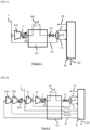
- the feed flow 1 is sent to the inlet of a stage C2 of a compressor.
- the gas 1 is mixed with a gas 13 to form a gas which is compressed in stage C2 to form the flow 7.
- the flow 7 compressed to a first pressure above 30 bara is cooled from a first temperature T1 to a third temperature T3 and cools in a cooler R1 by indirect contact with a fluid at a second temperature T2, for example water to an intermediate temperature of at least 40°C (for example between 40 and 60°C, for example 48-52°C) such that the density of the CO2 7 remains relatively low, below 400kg/m 3 , the CO2 being cooled to a third temperature T3.
- the fluid in the cooler R1 is oil, district heating water or boiler water. The fluid, for example water, in cooler R1 therefore recovers the heat of compression of the CO2.
- the CO2 partially cooled by the cooler R1 to the third temperature T3 is sent to a heat exchanger E1, for example of the plate and fin type. It cools from the third temperature T » to a fourth temperature T4 which is an intermediate temperature of this exchanger E1, lower than the first temperature and then leaves the exchanger to be cooled by a cooler R2 cooled by a fluid at an ambient temperature which is air or water. This ambient temperature is between 5 and 40°C.
- cooler R2 can be smaller and consume less fluid at room temperature.
- the CO2 cooled to a fifth temperature T5 and condensed or partially densified by the cooler R2 is subcooled in the heat exchanger E1 or in another heat exchanger and then expanded in a valve V1 to form a two-phase fluid which separates in a liquefaction and separation unit comprising a phase separator S.
- This separator S produces a gas 9 which is sent to a section B of the liquefaction unit and possibly separation by partial condensation and/or washing and/or distillation.
- the separator S also produces a liquid of which a part 11 is sent to section B of the liquefaction unit and the remainder 13 vaporizes and heats up in the heat exchanger E1 at a pressure substantially equal to the inlet pressure of stage C2.
- the liquid 13 can vaporize in the exchanger E1 upstream or downstream of the cooler R2.
- the vaporized liquid 13 is mixed with the gas 1 as mentioned.
- Section B produces an end product 23 which is liquid carbon dioxide, generally purer in carbon dioxide than stream 1.
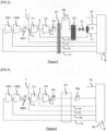
- the feed flow 1 is sent to the inlet of a stage C1 of a common compressor comprising n, here four, stages, including two stages CR1, CR2 upstream of stage C1.
- the gas 1 is mixed with a gas 17 to form a gas 3 which is compressed in stage C1 to form the flow 5.
- the flow 5 is mixed with the flow 13 and is then sent directly to the final stage C2 without having been cooled.
- the fluid in the cooler R1 can be oil, district heating water or boiler water.
- the fluid, for example water, of the cooler R1 therefore recovers heat of compression of the CO2.
- the CO2 partially cooled by the cooler R1 to the third temperature is sent to a heat exchanger, for example of the plate and fin type. It cools from the third temperature T3 to a fourth temperature T4 which is an intermediate temperature of this exchanger E1, lower than the first temperature and then leaves the exchanger to be cooled by a cooler R2 cooled by a fluid at an ambient temperature which is air or water. This ambient temperature is between 5 and 40°C.
- cooler R2 can be smaller and consume less fluid at room temperature.
- the CO2 cooled to a fifth temperature T5 and condensed or partially densified by the cooler R2 is subcooled in the heat exchanger E1 or in another heat exchanger and then is expanded in a valve V1 to form a two-phase fluid which separates in a liquefaction and separation unit comprising a phase separator S.
- This separator S produces a gas 9 which is sent to a section B of the liquefaction unit and possibly separation by partial condensation and/or washing and/or distillation.
- the separator S also produces a liquid of which a part 11 is sent to section B of the liquefaction unit and the remainder 13 vaporizes and heats up in the heat exchanger E1 at a pressure substantially equal to the outlet pressure of stage C1.
- the liquid 13 can vaporize in the exchanger E1 upstream or downstream of the cooler R2.
- the vaporized liquid 13 is mixed with the gas 5 as mentioned.
- Three other gaseous CO2 flows 21, 19, 17, at the inlet pressures of stages CR1, CR2 and C1 respectively, coming from section B are heated in exchanger E1 and are sent to the inlet of stages CR1, CR2 and C1 respectively.
- the pressure of flow 19 is lower than that of 17.
- the pressure of flow 21 is lower than that of 19.
- These gaseous flows 17, 19, 21 are produced during the liquefaction and/or separation by washing and/or distillation and/or partial condensation process which takes place in section B. At least one of the flows 17, 19, 21 can be produced in liquid form, vaporized in section B and sent as gas to exchanger E1.
- Section B produces an end product 23 which is liquid carbon dioxide, generally purer in carbon dioxide than stream 1.
- Gas 21 is compressed in stage CR1 then mixed with gas 19 and sent to the next stage CR2 without intermediate cooling.
- the compressed gas in stage CR2 is cooled by cooler RR1 and then is mixed with feed flow 1 and gas 17.
- the common compressor CR1, CR2, C1, C2 comprises n, here four, stages on the same axis and only n-2, here two, coolers, including an intermediate cooler RR1 between stages CR2 and C1 and a final cooler R1 downstream of the last stage C2.
- FIG.3 shows an alternative process to that of the Figure 1 in which only flow 13 is used to cool the gas coming from cooler R2 upstream of valve V1 in exchanger E2. Gases 17, 19, 21 do not pass into exchanger E2 but are heated in heat exchanger E1 and are sent respectively upstream of stage C1, upstream of stage CR2 and upstream of stage CR1. Here again at least one of the flows 17, 19, 21 can be produced in liquid form, vaporized in section B and sent as gas to exchanger E1.
- the E2 exchanger can be of a type allowing the exchange of heat between only two fluids, for example a shell and tube exchanger.
- FIG.4 still shows an alternative method of the Figure 1 in which the separation unit does not include a phase separator S or a valve V1.
- Unit B is a liquefaction or separation unit by distillation and/or washing and/or partial condensation.
- the unit also produces CO2-rich gases 14, 17, 19, 21 respectively at the pressures between stages C1 and C2, between stages CR2 and C1, between stages CR1 and CR2 and upstream of stage CR1. At least one of the flows 14, 17, 19, 21 is produced in liquid form, vaporized in section B and sent as gas to exchanger E1.
- coolers between stages CR1 and CR2 and between stages C1 and C2 are absent, while cooler RR1 and cooler R1 are present.
- the presence of cooler RR1 is also optional.
- the number of gases reheated and recycled, each at a different pressure is strictly equal to the number of compressor stages. It will be understood that the number of compressor stages can vary.
- the number of reheated gases, each at its own pressure may be less than the number of stages, for example equal to n-1, so that for certain stages, no flow is recycled directly upstream of the stage.
- the outlet pressure of the last stage of compressor C2 may be supercritical.
- liquefaction will include the densification of a supercritical gas or partial liquefaction.
Landscapes
- Engineering & Computer Science (AREA)
- Physics & Mathematics (AREA)
- Mechanical Engineering (AREA)
- Thermal Sciences (AREA)
- General Engineering & Computer Science (AREA)
- Chemical & Material Sciences (AREA)
- Chemical Kinetics & Catalysis (AREA)
- Separation By Low-Temperature Treatments (AREA)
Claims (16)
- Verfahren zur Verflüssigung und gegebenenfalls Abtrennung eines CO2-reichen Beschickungsstroms, umfassend die folgenden Schritte:a) Verdichtung (C1, C2) des Versorgungsstroms (1) von einem Anfangsdruck auf einen ersten Druck von mehr als 30 bara, um einen Versorgungsstrom (7) mit dem ersten Druck und bei einer ersten Temperatur zu erhalten,b) Kühlen des Speisestroms bei dem ersten Druck und der ersten Temperatur durch einen Wasser- oder Ölstrom mit einer zweiten Temperatur, die niedriger ist als die erste Temperatur, um einen Speisestrom mit dem ersten Druck und einer dritten Temperatur zu bilden,c) Kühlung des Speisestroms bei dem ersten Druck und der dritten Temperatur einen Speisestrom mit dem ersten Druck und einer vierten Temperatur durch Wärmeaustausch mit mindestens einem Strom (13, 14, 17, 19, 21) zu bilden, der durch Erhitzen einer Flüssigkeit erzeugt wird, wobei diese Flüssigkeit aus der Verflüssigung und gegebenenfalls der Trennung des Speisestroms stammtd) Kühlen (R2) des Zufuhrstroms bei dem ersten Druck und bei der vierten Temperatur 20 durch Wärmeaustausch mit einem Fluidstrom bei einer Temperatur zwischen 5 und 40°C, der Luft oder Wasser ist, um einen Zufuhrstrom bei dem ersten Druck und bei einer fünften Temperatur zu bilden, und wobei mindestens ein Teil des Zufuhrstroms bei dem ersten Druck und der fünften Temperatur verflüssigt und gegebenenfalls durch Teilkondensation und/oder durch Destillation abgetrennt wird, um ein flüssiges Produkt (11, 13, 23) zu bilden, wobei gegebenenfalls ein Teil des flüssigen Teils ebenfalls durch Teilkondensation und/oder durch Destillation abgetrennt wird.
- Verfahren nach Anspruch 1, bei dem der Wasser- oder Ölstrom in Schritt b) von der zweiten Temperatur auf eine Temperatur von von mehr als 40°C, vorzugsweise mehr als 80°C oder sogar mehr als 90°C erhitzt wird.)
- Verfahren nach einem der Ansprüche 1 und 2, das die folgenden Schritte umfasste) Abkühlung des Versorgungsstroms bei dem ersten Druck und der fünften Temperatur auf eine sechste Temperatur,f)Die Vorschubgeschwindigkeit bei der sechsten Temperatur wird auf einen einem zweiten Druck von mehr als 5,1 bar und einer siebten Temperatur von weniger als
Temperatur, aber über -56,6°C, wobei sich ein zweiphasiges Fluid bildet, das in einen gasförmigen Teil (9) und einen flüssigen Teil (11, 13) getrennt wird,g) mindestens ein Teil (13) des flüssigen Teils tauscht Wärme mit dem Speisestrom aus, um in den Schritten c) und/oder e) eine Kühlung zu bewirken, undh) zumindest ein Teil des gasförmigen Teils verflüssigt wird und gegebenenfalls durch partielle Kondensation und/oder Destillation getrennt werden, um das zu bilden Flüssigkeit (23), wobei möglicherweise ein Teil des flüssigen Teils auch durch Teilkondensation und/oder Destillation abgetrennt wird. - Verfahren nach Anspruch 3, bei dem die Kühlung von Schritt c) in einem ersten Wärmetauscher (E1) und die Kühlung von Schritt e) in einem zweiten Wärmetauscher (E2) erfolgt.
- Verfahren nach Anspruch 3, bei dem die Kühlung in Schritt c) und Schritt e) findet in einem einzigen Wärmetauscher (E1) statt.
- Verfahren nach einem der vorhergehenden Ansprüche, bei dem die Flüssigkeit aus der Verflüssigung und eventuellen Abtrennung des Speisestroms wird zum Wärmeaustausch mit dem Speisestrom geleitet und bildet einen Strom, der sich in Schritt c) und möglicherweise in Schritt e) erwärmt.
- Verfahren nach einem der vorhergehenden Ansprüche, bei dem der während der Abkühlung der Schritte c) und gegebenenfalls e) erwärmte Strom (13, 14, 17, 19, 21) zum Eingang einer Verdichtungsstufe (C1, C2) geleitet wird, in der der Speisestrom (1) verdichtet wird.
- Verfahren nach Anspruch 7, bei dem der Strom (13, 14, 17, 19, 21) dem Einlass einer Verdichtungsstufe (CR1, C2) mit einem Druck zugeführt wird, der gleich oder größer als der Ausgangsdruck, vorzugsweise aber kleiner als der erste Druck ist.
- Verfahren nach einem der vorhergehenden Ansprüche 3 bis 5 und 6 bis 8, wenn die Ansprüche 6 bis 8 von Anspruch 3 abhängen, bei dem mindestens ein Gasstrom (14, 17, 19, 21), der bei der Verflüssigung und gegebenenfalls Abtrennung des Speisestroms erzeugt wird, mit einer Temperatur über 0°C zur Erwärmung durch Wärmeaustausch mit dem Zufuhrstrom (1), der sich während der Schritte c) und gegebenenfalls e) abkühlt, wobei der mindestens eine Gasstrom (CR1, CR2) von einem Druck, der höchstens gleich dem Anfangsdruck ist, verdichtet wird und dann mit dem Versorgungsstrom (1) mit dem Ausgangsdruck gemischt.
- Verfahren nach Anspruch 9, bei dem der mindestens eine Gasstrom (14, 17, 19, 21), der während der Verflüssigung und gegebenenfalls der Abtrennung des Speisestroms erzeugt wird, durch Verdampfen einer Flüssigkeit erzeugt wird, die während der Verflüssigung oder Abtrennung des Speisestroms erzeugt wird.
- Verfahren nach mindestens einem der vorhergehenden Ansprüche, bei dem mindestens mindestens einen Verdichtungsschritt (C1, C2) des Speisestroms (1) oder nach Anspruch 9 oder 10, bei dem mindestens ein Verdichtungsschritt (CR1, CR2) des mindestens einen Gasstroms (14, 17, 19, 21) adiabatisch ist.
- Verfahren nach mindestens einem der vorhergehenden Ansprüche, bei dem der Wasser- oder Ölstrom bei der zweiten Temperatur auf mindestens 60°C erhitzt wird. und möglicherweise weniger als 150°C während Schritt b).
- Verfahren nach mindestens einem der vorhergehenden Ansprüche, bei dem die zweite Temperatur zwischen 5 und 50°C liegt.
- Verfahren nach mindestens einem der vorhergehenden Ansprüche, bei dem die dritte Temperatur zwischen 40°C und 60°C oder sogar 50°C liegt.
- Verfahren nach mindestens einem der vorhergehenden Ansprüche, bei dem die Dichte des Speisestroms bei der fünften Temperatur über 400 kg/m3, oder sogar über 600 kg/m3 liegt.
- Apparat zur Verflüssigung und gegebenenfalls Abtrennung eines CO2-reichen Versorgungstroms mit einem Kompressor (C1, C2) zur Verdichtung das Futtermittel von einem Anfangsdruck auf einen ersten Druck von mehr als 30 bar zu bringen, um ein Versorgungstrom (7) mit dem ersten Druck zu erhalten und bei einer ersten Temperatur, einen ersten Wärmetauscher (R1), der strömungstechnisch mit dem Kompressor verbunden ist, um das Versorgungstrom bei dem ersten Druck und der ersten Temperatur durch indirekten Wärmeaustausch mit einem Wasser- oder Ölstrom bei einer zweiten Temperatur, die niedriger als die erste Temperatur ist, zu kühlen, der sich erwärmt, um einen Versorgungstrom bei dem ersten Druck und bei einer dritten Temperatur, die höher als die erste Temperatur ist, zu bilden, einen zweiten Wärmetauscher (E1), der strömungstechnisch mit dem ersten Wärmetauscher verbunden ist, um das Versorgundstrom bei der ersten Temperatur zu kühlen. Druck und der dritten Temperatur, um einen Versorgungstrom mit dem ersten Druck und einer vierten Temperatur durch Wärmeaustausch mit mindestens einem Strom (13, 14, 17, 19, 21) zu bilden, der durch Erhitzen einer aus der Verflüssigung und eventuellen Trennung des Versorgungstroms resultierenden Flüssigkeit erzeugt wird, einen dritten Wärmetauscher (R2), der strömungstechnisch mit dem zweiten Wärmetauscher verbunden ist, um den Versorgungstrom bei dem ersten Druck und bei der vierten Temperatur durch Wärmeaustausch mit einem Fluidstrom zu kühlen, der Luft oder Wasser mit einer Temperatur zwischen 5 und 40°C ist, um einen Speisestrom bei dem ersten Druck und bei einer fünften Temperatur zu bilden, und Mittel (V1, B) zur Verflüssigung und gegebenenfalls Abtrennung durch Teilkondensation und/oder Destillation mindestens eines Teils des Versorgungstroms bei dem ersten Druck und bei der fünften Temperatur, um ein flüssiges Produkt (11, 23) zu bilden, wobei diese Mittel strömungstechnisch mit dem dritten Wärmetauscher verbunden sind.
Applications Claiming Priority (1)
| Application Number | Priority Date | Filing Date | Title |
|---|---|---|---|
| FR2212380A FR3142538B1 (fr) | 2022-11-28 | 2022-11-28 | Procédé et appareil de liquéfaction de CO2 ou de séparation de CO2 par distillation |
Publications (2)
| Publication Number | Publication Date |
|---|---|
| EP4375602A1 EP4375602A1 (de) | 2024-05-29 |
| EP4375602B1 true EP4375602B1 (de) | 2025-06-11 |
Family
ID=85018792
Family Applications (1)
| Application Number | Title | Priority Date | Filing Date |
|---|---|---|---|
| EP23211892.7A Active EP4375602B1 (de) | 2022-11-28 | 2023-11-24 | Verfahren und vorrichtung zur verflüssigung und gegebenenfalls trennung von co2 durch destillation |
Country Status (3)
| Country | Link |
|---|---|
| EP (1) | EP4375602B1 (de) |
| CA (1) | CA3220225A1 (de) |
| FR (1) | FR3142538B1 (de) |
Family Cites Families (6)
| Publication number | Priority date | Publication date | Assignee | Title |
|---|---|---|---|---|
| JPS6484087A (en) * | 1987-09-24 | 1989-03-29 | Jgc Corp | Manufacture of liquefied carbon dioxide |
| RU2376537C1 (ru) * | 2008-09-22 | 2009-12-20 | ОАО "Тольяттиазот" | Способ ожижения диоксида углерода |
| WO2010112539A2 (de) * | 2009-04-01 | 2010-10-07 | Siemens Aktiengesellschaft | Verdichtersystem für eine prozessgasanlage mit wärmerückeinspeisung und die prozessgasanlage zur kohlenstoffdioxidgas-abscheidung |
| FR2974167B1 (fr) | 2011-04-14 | 2015-11-06 | Air Liquide | Procede et appareil de liquefaction d'un gaz |
| AU2016236744B2 (en) * | 2015-03-23 | 2021-05-20 | Ptx Technologies Inc. | Industrial and hydrocarbon gas liquefaction |
| CN108709367A (zh) * | 2018-05-22 | 2018-10-26 | 中石化宁波工程有限公司 | 一种二氧化碳的液化装置及使用方法 |
-
2022
- 2022-11-28 FR FR2212380A patent/FR3142538B1/fr active Active
-
2023
- 2023-11-17 CA CA3220225A patent/CA3220225A1/fr active Pending
- 2023-11-24 EP EP23211892.7A patent/EP4375602B1/de active Active
Also Published As
| Publication number | Publication date |
|---|---|
| CA3220225A1 (fr) | 2024-05-28 |
| FR3142538B1 (fr) | 2024-11-15 |
| FR3142538A1 (fr) | 2024-05-31 |
| EP4375602A1 (de) | 2024-05-29 |
Similar Documents
| Publication | Publication Date | Title |
|---|---|---|
| US20140083132A1 (en) | Process for liquefaction of natural gas | |
| TWI379986B (en) | System to cold compress an air stream using natural gas refrigeration | |
| JPH11504104A (ja) | 流体流の冷却 | |
| US20150300734A1 (en) | Method for Separating a Carbon Dioxide-rich Gas by Partial Condensation and Permeation | |
| EP1014020B1 (de) | Kryogenisches Luftzerleggungsverfahren | |
| WO2013167817A2 (fr) | Procédé et appareil de séparation d'air par distillation cryogénique | |
| EP4302028A1 (de) | Verfahren und vorrichtung zur verflüssigung eines co2-reichen gases | |
| EP4325150B1 (de) | Verfahren und vorrichtung zur kühlung von wasserstoff | |
| EP4375602B1 (de) | Verfahren und vorrichtung zur verflüssigung und gegebenenfalls trennung von co2 durch destillation | |
| EP2938414B1 (de) | Verfahren und vorrichtung zur abscheidung eines kohlendioxidreichen gases | |
| EP4279848B1 (de) | Verfahren und vorrichtung zur kühlung eines co2-reichen stroms | |
| CA3259530A1 (en) | Method and plant for separation of carbon dioxide (co2) | |
| FR2956478A1 (fr) | Procede et appareil de separation d'air par distillation cryogenique | |
| EP4337901A1 (de) | Verfahren und vorrichtung zur verflüssigung eines kohlendioxidreichen gases | |
| FR2919717A1 (fr) | Procede et appareil de separation d'air avec compression de produit | |
| FR3150853A1 (fr) | Procédé et appareil de liquéfaction et/ou de solidification d’un gaz riche en dioxyde de carbone | |
| EP4493871B1 (de) | Verfahren und vorrichtung zur kühlung von wasserstoff | |
| CN107429967B (zh) | 使用从液化天然气的蒸发中获得的冷能回收来液化氮的设备 | |
| EP3058296B1 (de) | Verfahren zur stickstoffentfernung aus erdgas mit oder ohne heliumgewinnung | |
| CN118575048A (zh) | 用于冷却二氧化碳和氢气的方法和设备 | |
| EP4545166A1 (de) | Verfahren und vorrichtung zur destillation eines gemisches aus kohlendioxid, kohlenmonoxid und stickstoff | |
| WO2024235661A1 (fr) | Procédé et appareil de séparation d'un mélange contenant du co2 |
Legal Events
| Date | Code | Title | Description |
|---|---|---|---|
| PUAI | Public reference made under article 153(3) epc to a published international application that has entered the european phase |
Free format text: ORIGINAL CODE: 0009012 |
|
| STAA | Information on the status of an ep patent application or granted ep patent |
Free format text: STATUS: THE APPLICATION HAS BEEN PUBLISHED |
|
| AK | Designated contracting states |
Kind code of ref document: A1 Designated state(s): AL AT BE BG CH CY CZ DE DK EE ES FI FR GB GR HR HU IE IS IT LI LT LU LV MC ME MK MT NL NO PL PT RO RS SE SI SK SM TR |
|
| STAA | Information on the status of an ep patent application or granted ep patent |
Free format text: STATUS: REQUEST FOR EXAMINATION WAS MADE |
|
| 17P | Request for examination filed |
Effective date: 20241129 |
|
| RBV | Designated contracting states (corrected) |
Designated state(s): AL AT BE BG CH CY CZ DE DK EE ES FI FR GB GR HR HU IE IS IT LI LT LU LV MC ME MK MT NL NO PL PT RO RS SE SI SK SM TR |
|
| GRAP | Despatch of communication of intention to grant a patent |
Free format text: ORIGINAL CODE: EPIDOSNIGR1 |
|
| STAA | Information on the status of an ep patent application or granted ep patent |
Free format text: STATUS: GRANT OF PATENT IS INTENDED |
|
| INTG | Intention to grant announced |
Effective date: 20250324 |
|
| GRAS | Grant fee paid |
Free format text: ORIGINAL CODE: EPIDOSNIGR3 |
|
| GRAA | (expected) grant |
Free format text: ORIGINAL CODE: 0009210 |
|
| STAA | Information on the status of an ep patent application or granted ep patent |
Free format text: STATUS: THE PATENT HAS BEEN GRANTED |
|
| AK | Designated contracting states |
Kind code of ref document: B1 Designated state(s): AL AT BE BG CH CY CZ DE DK EE ES FI FR GB GR HR HU IE IS IT LI LT LU LV MC ME MK MT NL NO PL PT RO RS SE SI SK SM TR |
|
| REG | Reference to a national code |
Ref country code: GB Ref legal event code: FG4D Free format text: NOT ENGLISH |
|
| REG | Reference to a national code |
Ref country code: CH Ref legal event code: EP |
|
| REG | Reference to a national code |
Ref country code: IE Ref legal event code: FG4D Free format text: LANGUAGE OF EP DOCUMENT: FRENCH |
|
| REG | Reference to a national code |
Ref country code: DE Ref legal event code: R096 Ref document number: 602023003959 Country of ref document: DE |
|
| PG25 | Lapsed in a contracting state [announced via postgrant information from national office to epo] |
Ref country code: ES Free format text: LAPSE BECAUSE OF FAILURE TO SUBMIT A TRANSLATION OF THE DESCRIPTION OR TO PAY THE FEE WITHIN THE PRESCRIBED TIME-LIMIT Effective date: 20250611 Ref country code: FI Free format text: LAPSE BECAUSE OF FAILURE TO SUBMIT A TRANSLATION OF THE DESCRIPTION OR TO PAY THE FEE WITHIN THE PRESCRIBED TIME-LIMIT Effective date: 20250611 |
|
| REG | Reference to a national code |
Ref country code: LT Ref legal event code: MG9D |
|
| PG25 | Lapsed in a contracting state [announced via postgrant information from national office to epo] |
Ref country code: GR Free format text: LAPSE BECAUSE OF FAILURE TO SUBMIT A TRANSLATION OF THE DESCRIPTION OR TO PAY THE FEE WITHIN THE PRESCRIBED TIME-LIMIT Effective date: 20250912 Ref country code: NO Free format text: LAPSE BECAUSE OF FAILURE TO SUBMIT A TRANSLATION OF THE DESCRIPTION OR TO PAY THE FEE WITHIN THE PRESCRIBED TIME-LIMIT Effective date: 20250911 |
|
| REG | Reference to a national code |
Ref country code: NL Ref legal event code: MP Effective date: 20250611 |
|
| PG25 | Lapsed in a contracting state [announced via postgrant information from national office to epo] |
Ref country code: BG Free format text: LAPSE BECAUSE OF FAILURE TO SUBMIT A TRANSLATION OF THE DESCRIPTION OR TO PAY THE FEE WITHIN THE PRESCRIBED TIME-LIMIT Effective date: 20250611 |
|
| PG25 | Lapsed in a contracting state [announced via postgrant information from national office to epo] |
Ref country code: HR Free format text: LAPSE BECAUSE OF FAILURE TO SUBMIT A TRANSLATION OF THE DESCRIPTION OR TO PAY THE FEE WITHIN THE PRESCRIBED TIME-LIMIT Effective date: 20250611 |
|
| PG25 | Lapsed in a contracting state [announced via postgrant information from national office to epo] |
Ref country code: RS Free format text: LAPSE BECAUSE OF FAILURE TO SUBMIT A TRANSLATION OF THE DESCRIPTION OR TO PAY THE FEE WITHIN THE PRESCRIBED TIME-LIMIT Effective date: 20250911 |
|
| PG25 | Lapsed in a contracting state [announced via postgrant information from national office to epo] |
Ref country code: LV Free format text: LAPSE BECAUSE OF FAILURE TO SUBMIT A TRANSLATION OF THE DESCRIPTION OR TO PAY THE FEE WITHIN THE PRESCRIBED TIME-LIMIT Effective date: 20250611 |
|
| PG25 | Lapsed in a contracting state [announced via postgrant information from national office to epo] |
Ref country code: NL Free format text: LAPSE BECAUSE OF FAILURE TO SUBMIT A TRANSLATION OF THE DESCRIPTION OR TO PAY THE FEE WITHIN THE PRESCRIBED TIME-LIMIT Effective date: 20250611 |
|
| REG | Reference to a national code |
Ref country code: NL Ref legal event code: NE Effective date: 20251110 |
|
| PG25 | Lapsed in a contracting state [announced via postgrant information from national office to epo] |
Ref country code: PT Free format text: LAPSE BECAUSE OF FAILURE TO SUBMIT A TRANSLATION OF THE DESCRIPTION OR TO PAY THE FEE WITHIN THE PRESCRIBED TIME-LIMIT Effective date: 20251013 |
|
| REG | Reference to a national code |
Ref country code: AT Ref legal event code: MK05 Ref document number: 1802553 Country of ref document: AT Kind code of ref document: T Effective date: 20250611 |
|
| PG25 | Lapsed in a contracting state [announced via postgrant information from national office to epo] |
Ref country code: IS Free format text: LAPSE BECAUSE OF FAILURE TO SUBMIT A TRANSLATION OF THE DESCRIPTION OR TO PAY THE FEE WITHIN THE PRESCRIBED TIME-LIMIT Effective date: 20251011 |
|
| PGFP | Annual fee paid to national office [announced via postgrant information from national office to epo] |
Ref country code: DE Payment date: 20251119 Year of fee payment: 3 |
|
| PG25 | Lapsed in a contracting state [announced via postgrant information from national office to epo] |
Ref country code: SM Free format text: LAPSE BECAUSE OF FAILURE TO SUBMIT A TRANSLATION OF THE DESCRIPTION OR TO PAY THE FEE WITHIN THE PRESCRIBED TIME-LIMIT Effective date: 20250611 Ref country code: AT Free format text: LAPSE BECAUSE OF FAILURE TO SUBMIT A TRANSLATION OF THE DESCRIPTION OR TO PAY THE FEE WITHIN THE PRESCRIBED TIME-LIMIT Effective date: 20250611 |
|
| PGFP | Annual fee paid to national office [announced via postgrant information from national office to epo] |
Ref country code: BE Payment date: 20251119 Year of fee payment: 3 |
|
| PG25 | Lapsed in a contracting state [announced via postgrant information from national office to epo] |
Ref country code: CZ Free format text: LAPSE BECAUSE OF FAILURE TO SUBMIT A TRANSLATION OF THE DESCRIPTION OR TO PAY THE FEE WITHIN THE PRESCRIBED TIME-LIMIT Effective date: 20250611 |
|
| PG25 | Lapsed in a contracting state [announced via postgrant information from national office to epo] |
Ref country code: PL Free format text: LAPSE BECAUSE OF FAILURE TO SUBMIT A TRANSLATION OF THE DESCRIPTION OR TO PAY THE FEE WITHIN THE PRESCRIBED TIME-LIMIT Effective date: 20250611 |
|
| PG25 | Lapsed in a contracting state [announced via postgrant information from national office to epo] |
Ref country code: EE Free format text: LAPSE BECAUSE OF FAILURE TO SUBMIT A TRANSLATION OF THE DESCRIPTION OR TO PAY THE FEE WITHIN THE PRESCRIBED TIME-LIMIT Effective date: 20250611 |
|
| PG25 | Lapsed in a contracting state [announced via postgrant information from national office to epo] |
Ref country code: SK Free format text: LAPSE BECAUSE OF FAILURE TO SUBMIT A TRANSLATION OF THE DESCRIPTION OR TO PAY THE FEE WITHIN THE PRESCRIBED TIME-LIMIT Effective date: 20250611 |
|
| PG25 | Lapsed in a contracting state [announced via postgrant information from national office to epo] |
Ref country code: RO Free format text: LAPSE BECAUSE OF FAILURE TO SUBMIT A TRANSLATION OF THE DESCRIPTION OR TO PAY THE FEE WITHIN THE PRESCRIBED TIME-LIMIT Effective date: 20250611 |