EP4375219A2 - Anordnung zur automatisierten logischen kopplung an anhängerabteile - Google Patents
Anordnung zur automatisierten logischen kopplung an anhängerabteile Download PDFInfo
- Publication number
- EP4375219A2 EP4375219A2 EP24169947.9A EP24169947A EP4375219A2 EP 4375219 A2 EP4375219 A2 EP 4375219A2 EP 24169947 A EP24169947 A EP 24169947A EP 4375219 A2 EP4375219 A2 EP 4375219A2
- Authority
- EP
- European Patent Office
- Prior art keywords
- trailer
- wireless communication
- silos
- silo
- connection means
- Prior art date
- Legal status (The legal status is an assumption and is not a legal conclusion. Google has not performed a legal analysis and makes no representation as to the accuracy of the status listed.)
- Pending
Links
Images





Classifications
-
- B—PERFORMING OPERATIONS; TRANSPORTING
- B65—CONVEYING; PACKING; STORING; HANDLING THIN OR FILAMENTARY MATERIAL
- B65G—TRANSPORT OR STORAGE DEVICES, e.g. CONVEYORS FOR LOADING OR TIPPING, SHOP CONVEYOR SYSTEMS OR PNEUMATIC TUBE CONVEYORS
- B65G67/00—Loading or unloading vehicles
- B65G67/02—Loading or unloading land vehicles
- B65G67/04—Loading land vehicles
- B65G67/06—Feeding articles or materials from bunkers or tunnels
-
- B—PERFORMING OPERATIONS; TRANSPORTING
- B65—CONVEYING; PACKING; STORING; HANDLING THIN OR FILAMENTARY MATERIAL
- B65G—TRANSPORT OR STORAGE DEVICES, e.g. CONVEYORS FOR LOADING OR TIPPING, SHOP CONVEYOR SYSTEMS OR PNEUMATIC TUBE CONVEYORS
- B65G43/00—Control devices, e.g. for safety, warning or fault-correcting
- B65G43/02—Control devices, e.g. for safety, warning or fault-correcting detecting dangerous physical condition of load carriers, e.g. for interrupting the drive in the event of overheating
-
- B—PERFORMING OPERATIONS; TRANSPORTING
- B65—CONVEYING; PACKING; STORING; HANDLING THIN OR FILAMENTARY MATERIAL
- B65G—TRANSPORT OR STORAGE DEVICES, e.g. CONVEYORS FOR LOADING OR TIPPING, SHOP CONVEYOR SYSTEMS OR PNEUMATIC TUBE CONVEYORS
- B65G65/00—Loading or unloading
- B65G65/005—Control arrangements
-
- B—PERFORMING OPERATIONS; TRANSPORTING
- B65—CONVEYING; PACKING; STORING; HANDLING THIN OR FILAMENTARY MATERIAL
- B65G—TRANSPORT OR STORAGE DEVICES, e.g. CONVEYORS FOR LOADING OR TIPPING, SHOP CONVEYOR SYSTEMS OR PNEUMATIC TUBE CONVEYORS
- B65G67/00—Loading or unloading vehicles
- B65G67/02—Loading or unloading land vehicles
-
- B—PERFORMING OPERATIONS; TRANSPORTING
- B65—CONVEYING; PACKING; STORING; HANDLING THIN OR FILAMENTARY MATERIAL
- B65G—TRANSPORT OR STORAGE DEVICES, e.g. CONVEYORS FOR LOADING OR TIPPING, SHOP CONVEYOR SYSTEMS OR PNEUMATIC TUBE CONVEYORS
- B65G2203/00—Indexing code relating to control or detection of the articles or the load carriers during conveying
- B65G2203/04—Detection means
- B65G2203/042—Sensors
- B65G2203/046—RFID
Definitions
- the invention relates to an arrangement for unloading a trailer comprising goods e.g. bulk material, and correct delivery of such bulk material to a storage facility such as for example a particular silo amongst a plurality of other neighbouring silos, by means of an automated logical coupling mechanism between the trailer and the storage facility.
- goods e.g. bulk material
- a storage facility such as for example a particular silo amongst a plurality of other neighbouring silos
- Trailers are designed and often custom-made depending on the application or type of freight they are transporting.
- trailers comprise of a container and can host several compartments within the container.
- goods e.g. bulk such as for example stock nutrition is stored to be transferred to silos at farmers or customers' premises. It is essential that the goods are delivered to the intended silo or storage tank.
- the trailer truck is parked at significant distance of the silo to be supplied. Discharging of for instance bulk material can be done via modular hoses connected to the trailer on one hand and to the silo on the other hand.
- a human operator e.g.
- the truck driver performs the logical coupling or connecting of the hoses, leading to mistakes in delivery particularly at industrial or farm sites where multiple silos are installed close to each other. Such mistakes causing in particular administrative and logistics burden, additional overhead expenses, or may even turn out into wrong or dangerous supply of food to animals.
- the aim of the invention is to provide an arrangement for correct delivery of goods, such as for instance bulk material, from a trailer to a storage facility e.g. a silo, wherein the correctness of the delivery is guaranteed in an automated manner.
- goods such as for instance bulk material
- the invention relates to an arrangement for unloading a trailer comprising goods e.g. bulk material, and correct delivery of such bulk material to a storage facility such as for example a particular silo amongst a plurality of other neighbouring silos, by means of an automated logical coupling mechanism between the trailer and the one or more silos.
- a storage facility such as for example a particular silo amongst a plurality of other neighbouring silos.
- an arrangement comprising: a storage facility and a trailer.
- the storage facility comprises one or more silos, having each a joint such as for a example a supply valve or else an air outlet i.e. a joint for air exhaust, whereas the trailer is provided with a storage means (which may in itself have multiple compartments) and a connection means, being connected to the storage means, but also being connectable to one of the supply valves.
- a storage means which may in itself have multiple compartments
- connection means being connected to the storage means, but also being connectable to one of the supply valves.
- connection means being for example a reader
- connection itself herewith suggested is not necessarily a (close or direct) contact connection, and hence can as well be a virtual connection, such as for instance a wireless communication connection, or another type of radiation connection.
- the arrangement is characterized in that at least one of the one or more silos, preferably at the joint such as the supply valve, or at the air outlet of the at least one of the one or more silos is (for the purpose of automatic identification and establishing a logical coupling) provided with a first wireless communication means, being for example a tag that can be read by a reader.
- connection means is moreover movably connected to the storage means, meaning that the connection means can be moved from one position to another, without loss of being functionally related with each other. Changing position of the connection means may lead to a change in the connection provided, meaning either the type of connection (e.g.
- connection means is movable between a first unconnected joint position, or first unconnected valve position while referring to a supply valve as possible joint, and a second connected joint position, or second connected valve position, according to an embodiment in the vicinity of the first wireless communication means or e.g. tag.
- the first unconnected valve position is determined as the position wherein there is no connection made between the connection means and the supply valve of the one or more silos.
- the second connected valve position is defined as the position wherein a connection between the connection means and the supply valve of the one or more silos is made.
- connection means being movable refers to the fact that the connection means can be moved from one position to the other while staying attached or physically connected to the trailer or truck.
- the connection means is provided with a second wireless communication means, being capable to communicate with the first wireless communication means of the supply valve, and this in particular when the connection means is in connection with or connected to the supply valve, implying that the connection means is in the second connected valve position, due to what is mentioned above.
- the connection means or e.g. reader can also detect airflow through the joint.
- the sensing system is e.g. a flex or bend sensor for measuring the amount of deflection or bending, such amount being a measure or indication for the airflow passing in the air outlet or air exhaust.
- Other possible sensing systems for airflow detection are e.g. an accelerometer, or a tilt sensor.
- the trailer is provided with a third wireless communication means, being capable to communication with the connection means, while this connection means being in either the first unconnected or the second connected valve position.
- the connection means is provided with a fourth communication means being adapted for the communication with the third wireless communication means. While referring to a communication enabled between a third and a fourth wireless communication means, and hence amongst (two) wireless communication means, the communication itself is implied to be wireless communication.
- the type of communication or communication channel between the first wireless communication means and the second wireless communication means is based on NFC (Near Field Communication) technology.
- RFID technology could be used.
- the type of communication or communication channel between the trailer and the connection means, or in other words between the third wireless communication means and the fourth wireless communication means is based on a (private secured) preferably ad-hoc wireless technology capable of communicating over significant distance, such as for example LoRa or another technology capable of covering the distance between the silo and the trailer.
- the trailer is provided with an energy transfer means being capable to transfer energy to the connection means.
- the connection means is provided with energy reception means, being adapted for energy transfer with the energy transfer means from the trailer, while the trailer being adapted for energy transfer via this energy transfer means, when the connection means is in the first unconnected valve position, meaning that the connection means is not connected to the supply valve of the one or more silos.
- the connection means then being close to, attached to, connected to or in contact with the trailer.
- the connection means comprises an energy storage means, such as for instance a battery, for storing the transferred or received energy.
- the trailer is provided with a computer control system being in wired connection with or either wirelessly connected to the third wireless communication means.
- the connection means may further comprise a processor, for processing data that is received, transferred or transmitted via the wireless communication mentioned.
- the first wireless communication means comprises a first antenna and an accompanying first wireless frontend e.g. an RF chip connected to the first antenna
- the second wireless communication means comprises a second antenna and a second wireless frontend, being adapted to the first antenna and the first wireless frontend respectively.
- the connection means is adapted for secure connection for a storage facility comprising at least two silos, each with a joint or supply valve, wherein the supply valves are provided in the vicinity of each other. In other words, the supply valves are placed or located in each other's neighbourhood. They are even that close to each other that it may be necessary that the wireless communication needs to be directed, such that there is no interference with unwanted silos, and only the intended silo is in communication.
- the arrangement further comprises an antenna system defined by the first and the second antenna as mentioned above, while being adapted in wireless communication therein between, whenever the connection means is brought in the second connected valve position, i.e. the connection means is connected with and focused to the supply valve of the one or more silos.
- the wireless communication of the antenna system is operating within a predefined angle, such that the communication is more directed and hence only the intended supply valve or silo becomes in connection, whereas the other neighbouring supply valves or silos are as a consequence beyond reach.
- the invention relates to mechanical connecting, which can in itself, be performed manually e.g. by the trailer driver, or automated or assisted by automation means like robots, in combination with automated identification (and hence all the requirement communication means) of the connected pair (in casu the supply valve and (assumed to be) accompanying connection means), supporting determining whether such connection is valid or safe, to thereby establish an automated logical (in the sense that the pair belongs together) coupling, which may be further used either as signal to the trailer driver but also a (electrical) signal to machinery (like pumps) attached to the storage means (e.g. to unlock it and start supporting the supply between silo and trailer).
- the invention provides an arrangement providing automated identification for the purpose of establishing (automatically) a logical coupling, if justified based on the identification information obtained, and on top of the mechanical connection.
- Such arrangement hence enables correct delivery of goods, in an (semi-) automated manner, by providing technical functions such as automated identification and subsequent automated logical coupling.
- the automation loop is herewith closed.
- the connection means and/or valves are for the purpose of automatic identification and establishing a logical coupling.
- a silo may have as associated equipment a plurality of in- or out-lets or connections, even having various shapes, and that even one or more of these in- or out-lets are not supposed to be used for supply of material from and to a trailer.
- false supply valves may as a mistake be used by the trailer driver or operator, typically such false supply valve would not be provided with wireless communication means to identify it as a valid connection.
- connection means is provided, connected in terms of material flow to a storage means of a trailer, and further being movably and physically connected or attached to either the storage means of a trailer in a first unconnected joint or valve position or either to a joint for air exhaust or supply valve of one or more silos being part of a storage facility in a second connected joint or valve position, this latter connected meaning again being physically connected or attached thereto.
- the connection means is for example a reader.
- At least one of said one or more silos preferably at one of the joints amongst which a joint for air exhaust and/or the supply valve, is (for the purpose of automatic identification and establishing a logical coupling) provided with a first wireless communication means, such as for example a tag
- the connection means is provided with a second wireless communication means, capable to communicate with the first wireless communication means of the supply valve, and this particularly whenever the connection means is in the second connected valve position, meaning that the connection means is connected to the supply valve, according to an embodiment in the vicinity of the first wireless communication means or e.g. tag.
- the connection means is particularly suited for connection with a supply valve of a silo, and therefore could also be referred to as a silo valve connection means.
- the connection means or e.g. reader is characterized in that it can also detect airflow through the joint. In case of a reader for instance, such reader can be provided with a sensing system for detecting such airflow.
- connection means suited for use when the trailer is provided with a third wireless communication means, is further provided with a fourth communication means adapted for communication with the third wireless communication means, while being in either the first unconnected or the second connected joint or valve position.
- connection means suited for use when the trailer is provided with an energy transfer means, is further provided with energy reception means adapted for transfer of energy, as received from the energy transfer means provided onto the trailer, when the connection means is in the first unconnected valve position, more preferably the connection means comprises an energy storage means, such as for example a battery system.
- the connection means is adapted for secure connection for a storage facility comprising at least two silos, each with a joint e.g. a supply valve, wherein the supply valves are in the vicinity of each other.
- a trailer is provided with a storage means and a connection means in accordance with second aspect of the invention.
- the trailer is provided with a third wireless communication means adapted for communication with the fourth communication means.
- a joint such as a supply valve or else an air outlet i.e. a joint for air exhaust is provided, suited for silos of a storage facility comprising one or more silos, such silos being connectable to a connection means of a trailer, such trailer being provided with a storage means.
- the supply valve is moreover (for the purpose of automatic identification and establishing a logical coupling) provided with a first wireless communication means being adapted for wireless communication with the connection means whenever the connection means and the supply valve are physically connected to or in contact with each other.
- an arrangement comprising a storage facility comprising one or more silos, each with an air exhaust, and a closing system for such air exhaust provided with a collection means and a connection means, connectable to said collection means and connectable to one of said air exhaust, said arrangement being characterized in that said air exhaust is provided with a first wireless communication means, and said connection means being removable connected to said collection means while being in the vicinity of said first wireless communication means and herewith closing said air exhaust, and said connection means further being provided with a second wireless communication means, capable to communicate with said first wireless communication means when said connection means being connected to said collection means while being in the vicinity of said first wireless communication means.
- the connection means when connected to the collection means, may also detect the presence of airflow within the air exhaust.
- the collection means is for example a bag, being semi-permeable such that dust particles coming from the silo (via the air exhaust) together with the airflow can be captured, whereas the air itself can leave the bag through minuscule holes.
- the closing system may be further provided with a belt onto which the connection means can be fixed, whereas this belt can be used to attach the collection means to the air exhaust, and herewith closing the air exhaust.
- an arrangement comprising a storage facility having one or more silos, each with a joint for air exhaust and a joint or supply valve for transferring material to the one or more silos.
- the arrangement also comprises a trailer from which material is being transferred to the one or more silos.
- the trailer is provided with a storage means and a connection means connected to the storage means and connectable to one of the joints.
- the connection means is for example a reader.
- the arrangement is characterized in that at least one of the one or more silos is provided with a first wireless communication means, being for example a tag.
- the connection means is movable between a first unconnected joint position and a second connected joint position, according to an embodiment in the vicinity of the first wireless communication means or e.g. tag.
- the trailer is further provided with a second wireless communication means, capable to communicate with the first wireless communication means or e.g. tag, when the connection means or e.g. reader is in the second connected joint position.
- the arrangement is further characterized in that the connection means or e.g. tag can also detect airflow in the air exhaust when connected to the at least one of the one or more silos, preferably at one of the joints.
- a method for identifying whether the supply line between a storage means of a trailer and a joint or supply valve of a silo for transferring material from the trailer to a storage facility comprising at least the silo with the joint amongst one or more silos, each having one or more joints being e.g. a supply valve or a joint for air exhaust, is correctly placed.
- the silo is provided with a first wireless communication means, being e.g. a tag.
- the identification method comprises the following steps. First, bringing a connection means, being e.g. a reader, related to the storage means, to the joint, being in the vicinity of the first wireless communication means or e.g. tag.
- connection means is provided with a second wireless communication means, capable to communicate with the first wireless communication means when the connection means is in a connected joint and characterized in that the connection means or e.g. reader can also detect airflow through the joint.
- the connection means or e.g. reader can also detect airflow through the joint.
- an arrangement comprising a storage arrangement, a storage facility with one or more silos, a trailer with a storage means, and a central control system.
- the storage arrangement can for example be seen as a bulk load facility or arrangement comprising of different compartments of bulk goods e.g. food bulk to be loaded in respective (corresponding) separated parts of the storage means of the trailer.
- the central control system and the trailer are adapted for wireless communication between each other, whereas the trailer is provided with a system for automated logical coupling between the trailer and the storage facility.
- the central control system is adapted for providing information (e.g. location information) on material as stored in the storage means of the trailer, such material having been transferred from the storage arrangement to the trailer.
- the trailer is adapted to release material as stored in its storage means to the appropriate of the one or more silos of the storage facility, based on combining the information from the central control system with signals received from the system for automated logical coupling.
- the appropriate is meant the correct or justified one as identified by means of an identification method such as for example referred to above in previous aspect, i.e. the method for identifying whether the supply line between a storage means of a trailer and a joint or supply valve of a silo for transferring material from the trailer to a storage facility is correctly placed.
- a central control system comprising means for wireless communication with one or more trailers, and a database environment for information on material as stored in a storage means of the one or more trailers while having been transferred from a storage arrangement.
- a trailer is provided with a storage means.
- the trailer comprises means for wireless communication with a central control system and a system for automated logical coupling between the trailer and a storage facility comprising one or more silos.
- the trailer is adapted e.g. by means of providing a local control system within the trailer, to release material as stored in the storage means to the appropriate of the one or more silos of the storage facility, based on combining the information from the central control system with signals received from the system for automated logical coupling.
- a computer program product operable on a processing engine, for operating the functions of a central control system for one or more trailers according to the aspect above and/or of a local control system within a trailer.
- a nontransitory machine-readable storage medium is provided for storing the computer program product.
- a data format is provided, for use in wireless communication between a central control system, and one or more trailers with storage means, or their local control system in particular. The data format is adapted for carrying information on material such as e.g. bulk food as stored in the storage means from a storage arrangement to the trailer.
- an arrangement comprising: a storage facility and a trailer.
- the storage facility comprises one or more silos, having each a joint such as for a example a supply valve, whereas the trailer is provided with a storage means (which may in itself have multiple compartments) and a connection means, being connected to the storage means, but also being connectable to one of the supply valves.
- the connection means is a tangible and visible system or device, whereas the connection itself herewith suggested is not necessarily a (close or direct) contact connection, and hence can as well be a virtual connection, such as for instance a wireless communication connection, or another type of radiation connection.
- the arrangement is characterized in that the supply valve of the one or more silos is (for the purpose of automatic identification and establishing a logical coupling) provided with a first wireless communication means.
- the supply valve named as possible joint is not necessarily a valve, but may also be any type of connection means attached to or being part of the silo, and through which goods can be supplied to or from the silo.
- Other possible joints referred to are for instance pipes, couplers, or junctions.
- the wording supply valve is often used below, mainly to clarify how such joint may look like or can be interpreted as, by means of example.
- the connection means is moreover movably connected to the storage means, meaning that the connection means can be moved from one position to another.
- connection means may lead to a change in the connection provided, meaning either the type of connection (e.g. physical contact, wireless communication possible, inductive coupling enablement) or either the fact that there is all or not a connection remained with a connectable device or system due to the position change.
- the connection means is movable between a first unconnected joint position, or first unconnected valve position while referring to a supply valve as possible joint, and a second connected joint position, or second connected valve position.
- the first unconnected valve position is determined as the position wherein there is no connection made between the connection means and the supply valve of the one or more silos.
- the second connected valve position is defined as the position wherein a connection between the connection means and the supply valve of the one or more silos is made.
- the connection means being movable refers to the fact that the connection means can be moved from one position to the other while staying attached or physically connected to the trailer or truck.
- the connection means is provided with a second wireless communication means, being capable to communicate with the first wireless communication means of the supply valve, and this in particular when the connection means is in connection with or connected to the supply valve, implying that the connection means is in the second connected valve position, due to what is mentioned above. While referring to a communication enabled between a first and a second wireless communication means, and hence amongst (two) wireless communication means, the communication itself is implied to be wireless communication.
- the invention while providing the required special functionalities described, takes into account specifics of the arrangements in terms of required distances, operating (harsh) conditions and addresses this by providing an integrated approach in relation to (i) at electronic level (wireless) communication and related energy needs and (ii) at mechanical/physical level, the movability, the (safe) connections and a robust package.
- the invention addresses the mutual influences of those specifics and design choices.
- the invention relates to arrangements comprising a storage facility 10 and a trailer 30.
- the storage facility 10 is provided with one or more silos, each silo having a supply valve 20, whereas the trailer 30 is provided with a storage means 40 and a connection means 50.
- the storage means 40 on the trailer 30 contains or is intended to contain materials suited for storage in silos.
- the connection means 50 is connected to this storage means 40 and is connectable to one of the supply valves 20, to enable transfer of material from the trailer 30 to the silos.
- the invention relates to the above arrangements wherein the storage facility 10 comprises of at least two silos, each with a supply valve 20, wherein the valves 20 are occurring in the vicinity of each other, and wherein the connection means 50 is adapted to cope with the technical problems arising with such neighbouring silo-valve context.
- the invention relates to an adapted arrangement wherein the supply valve 20 is provided with a first wireless communication means 100 and an adapted connection means 50 being movably connected to the storage means 40 between a first unconnected (to said valve 20) and a second connected (to said valve 20) position P1, P2 and the connection means 50 further being provided with a second wireless communication means 110, capable to communicate 400 bilaterally with the first wireless communication means 100 when the connection means 50 being in the connected position P2, meaning that the connection means 50 is connected with the supply valve 20 of a silo.
- the bilateral or 2-way communication 400 means that communication is enabled to and from the silo, or to and from the connection means 50 of the trailer 30. Further, the trailer 30 may be provided with a third wireless communication means 200, being capable to communicate 410 bilaterally with a fourth communication means 210 provided within the connection means 50.
- the trailer 30 may comprise a hose 60 or another (type of tubular or cylindrical) means for transferring and discharging the material e.g. food from the storage means 40 of the trailer 30 to the silo of the storage facility 10.
- hose 60 is thus connected with the storage means 40 of the trailer 30 on one hand, and is connectable with a supply valve 20 of the silo (hence storage facility 10) on the other hand.
- the trailer 30 is also provided with an energy transfer means 310 being capable to transfer energy with the connection means 50.
- the connection means 50 is provided with an energy reception means 300, being adapted for energy transfer 500 with the energy transfer means 310 provided onto the trailer 30, when the connection means 50 is in the first unconnected valve position P1, meaning that the connection means 50 is not connected to the supply valve 20 of a silo.
- the connection means 50 being in the first unconnected valve position P1 is attached to, connected to, in contact with, close to or in the neighbourhood of the trailer 30, such that energy transfer 500 can take place either wired or else wirelessly such as e.g. via inductive coupling or RF wireless charging.
- connection means 50 may also comprise an energy storage means 320, such as for instance a battery, for storing the transferred or received energy.
- an energy storage means 320 such as for instance a battery
- a link 420 may be foreseen for exchanging data amongst them.
- the received or transmitted data from the communication 400 e.g. NFC or RFID
- the communication 410 e.g. LoRa
- the link 420 implicates that the second and the fourth wireless communication means 110, 210 are in some way also connected to each other, be it wired via an electronic platform onto which both are provided within the connection means 50, or either enabled wirelessly in a non-contact way.
- the trailer 30 can also be provided with a computer control system 220 being in wired connection with or either wirelessly connected to the third wireless communication means 200.
- the connection means 50 may further comprise a processor 230, for processing data that is received, transferred or transmitted via the wireless communications 400, 410 mentioned.
- the processor 230 is for instance integrated in an electronic board or platform onto which second and fourth wireless communications means 110, 210 may also be embedded.
- the first wireless communication means 100 may comprise a first antenna 520 and a first wireless frontend 530
- the second wireless communication means 110 may comprise a second antenna 510 and a second wireless frontend 500, being adapted to the first antenna 520 and the first wireless frontend 530 respectively.
- wireless frontend 500, 530 is for instance an RF chip connected to its respective antenna 510, 520.
- Figure 3(a) shows the connection means 50 placed in position P2, i.e. the second connected valve position P2, and hence being in connection with the supply valve 20 of a silo.
- the connection implies that a connection is made although not necessarily having physical contact of both parts.
- connection means 50 and the supply valve 20 may still be spaced apart although being physically rather close to each other, such that e.g. a near field communication between both is feasible.
- the connection means 50 is adapted for secure connection for a storage facility 10 comprising e.g. at least two silos, each with a supply valve 20.
- the storage facility 10 for instance comprises three silos, each having a supply valve 20, and moreover the three supply valves 20 (one for each silo) are provided in the vicinity of each other.
- the supply valves 20 are placed or located in each other's neighbourhood.
- the wireless communication system for the wireless communication 400 between connection means 50 and supply valve 20 comprises an antenna system defined by the first and the second antenna 520, 510 as mentioned above, while being adapted in wireless communication therein between, whenever the connection means 50 is brought in the second connected valve position P2, i.e. the connection means 50 is connected with and focused to the supply valve 20 of a silo.
- the wireless communication of the antenna system is operating within a predefined angle 540, such that the communication is more directed and hence only the intended supply valve 20 or silo becomes in connection, whereas the other neighbouring supply valves of adjacent silos are as a consequence beyond reach.
- the adapted arrangement should be intrinsically safe and secure itself, by providing a trust worth logic (on or available when needed) communication channels (as above explained), reliable robust physical components (such as the connection means with its required electronics) and given the particular context of possibly having multiple near-by valves (each possibly related to different materials), hence the sensitivity of the involved communication means (and their antennas in particular) must be adapted also to cope with such set-up.
- the above can be further supplemented with mechanical measures such as choice of suitable compatible forms for the parts of said connection means and the parts of said valves that need to connect to enable the wireless communication.
- the invention relates to an autonomous system for logically coupling a silo 1010 to a trailer 1030 with one or more compartments containing goods to be transferred to the silo 1010.
- the system comprises a contactless module 1050 to be mounted on or to be connected to a hose 1060, wherein the contactless module 1050 can wirelessly communicate 1400 on the one hand to a silo 1010 in close proximity, and on the other hand can wirelessly communicate 1410 to the trailer 1030.
- the proximity communication 1400 is a bidirectional communication between a proximity communication means 1110 being part of the module 1050 and a tag 1100 mounted, installed or attached onto the silo 1010.
- the remote communication 1410 is a bidirectional communication between a remote communication means 1210 being part of the module 1050 and another remote communication means 1200 mounted, installed or attached onto the trailer 1030.
- the two wireless technologies 1400, 1410 specifically can be functionally fit as follows:
- the approach to communicate with two low (power) technologies offers the combined advantages of wireless identification based on passive tags at a range limited to a secure close proximity, while the transferring of the goods can be controlled remotely.
- the module 1050 further comprises means, i.e. a wireless energy reception member 1300, for charging it without any cable connections.
- Wireless power charging is for instance further enabled by means of provisions or equipment installed onto the trailer 1030, and thus wireless power can be received from a wireless power transmitter 1310 provided on the trailer 1030.
- An on-board computer 1220 may also be installed on the trailer 1030.
- the autonomous system can provide non-ambiguous logical coupling of a silo to (a compartment of) a trailer 1030 in order to ensure correct transferring, e.g. loading or unloading of goods. Please note that while referring to the energy harvesting aspect, both terms power and energy are used while covering the same principle.
- the proximity communication 1400 between the hose 1060 and the silo 1010 can be based on inductive principles for which a tag 1100, e.g. passive, is mounted on the silo 1010.
- This tag 1100 can hold identification information of the silo 1010, and can be read by the module 1050.
- the module 1050 can hence be seen as a reader or a scanner. According to an embodiment, the module 1050 supplies energy to the tag 1100 for providing identification information.
- the contactless (i.e. no touching or physical contact with the tag is made) module 1050 can be implemented for example as schematically illustrated in Figure 5 .
- the (close) proximity communication 1400 can for example be implemented with Near Field Communication (NFC) technology, which conveniently limits the range to close proximity. It could also be implemented based on RFID technology wherein the power of the system is limited to avoid that the module 1050 would incidentally pick a signal from another nearby silo.
- NFC Near Field Communication
- the mechanical coupling of the system can be based on a specific shape of the module 1050 itself and a corresponding holder for this module 1050 at the side of the silo 1010, such that they couple smoothly without the need to fix them with specific effort from the operator:
- the remote communication 1410 can for example be implemented with Low Power Wide Area Network technology, such as for example LoRa, which is well suited to support low power connectivity up to several hundreds of meters.
- Low Power Wide Area Network technology such as for example LoRa
- the contactless energy harvesting can for example be implemented based on wireless power transfer.
- the charging component could be placed on the trailer 1030 such that the recharging can happen during the transportation.
- the module 1050 may further be provided with energy storage means 1320, i.e. a battery, for storing the wirelessly received power, as received by means of the wireless power receiver 1300.
- a computer processor 1230 may also be part of the module 1050, for example for processing the transferred data.
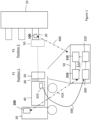
- Figure 6 shows an embodiment of a discharging system making use of an arrangement for automated logical coupling of a trailer 2030 to a silo 2010 in accordance with the invention.
- a screw is here used for the discharging system and is provided inside a connecting tube 2060, connecting together with the connection means 2050, the trailer 2030 with the silo 2010.
- a first wireless communication means or tag 2100 is provided onto the silo 2010, for example as indicated in Figure 6 , for enabling the automated logical coupling, i.e. the automated identification.
- FIG. 7 shows an embodiment of an arrangement for automated logical coupling of a trailer to a silo, in combination with the principle of airflow exhaust of a silo, in accordance with the invention.
- a collection means such as a dust bag 3080 is for instance attached to the outlet 3092 of the air exhaust 3090, herewith closing the air exhaust 3090 i.e. the pipe through which airflow 3091 including dust particles are exhausted.
- the closing is not entirely or hermetically, meaning that although dust particles are remained in the bag 3080, the air can leave the bag 3080 being porous or semi-permeable and hence provided with minuscule holes or pores.
- an identification system can also be included herewith. Therefore, the outlet 3092 of the air exhaust 3090 is e.g.
- a tag 3100 which can be read by a reader 3050 being comprised in a belt 3070 for attaching the dust bag 3080 to the outlet 3092 of the air exhaust 3090.
- the belt 3070 and hence the reader 3050 being fixed thereon are attached to the air exhaust outlet 3092 in the vicinity of the tag 3100 for enabling wireless communication 3400 amongst them.
- the reader 3050 can also detect airflow 3091, next to detecting the tag 3100. It is moreover noted that airflow 3091 can only be detected or maybe even observed visually when the hose is connected to the correct silo 3010, i.e. the silo 3010 where food supply is required.
- a double indication is herewith given for guaranteeing correct delivery of bulk material to a storage facility such as for example a particular silo amongst a plurality of other neighbouring silos, by means of an automated logical coupling mechanism between the trailer and the storage facility, and exhaust airflow detection.
- the invention in relation to the embodiment above, in general wording, as shown in Figure 8 , the invention relates to arrangements comprising a storage facility 10 and a trailer 30.
- the storage facility 10 is provided with one or more silos, each silo having a supply valve 20 and an air exhaust 2000
- the trailer 30 is provided with a storage means 40 and a connection means 50.
- the storage means 40 on the trailer 30 contains or is intended to contain materials suited for storage in silos.
- the connection means 50 is connected to this storage means 40 and is connectable to one of the air exhausts 2000 while further a supply means such as for example a pipe (not shown) is connectable to supply valves 20, to enable transfer of material from the trailer 30 to the silos.
- an arrangement comprising a storage facility 10 comprising one or more silos, each silo having a joint 2000 for air exhaust and a joint 20 as supply valve for transferring material, e.g. bulk food, there through to or from the silos.
- Such joints 20, 2000 can be separate joints, or either can be the same for both air exhaust and as supply valve, and hence having both functions integrated in one single joint.
- the arrangement also comprises a trailer 30, to or from which the material is transferred.
- the trailer 30 is provided with a storage means 40 and a connection means 50, e.g. a reader, connected to the storage means 40 and connectable to one of the joints 20, 2000.
- a hose (not shown) comparable to 60 in Figure 1 , is provide between the storage means 40 and the supply valve 20 for containing and delivering bulk goods.
- the connection means 50 e.g. a reader
- the connection 65 is connected with the storage means 40 by means of the connection 65, which can be a wired or wireless connection.
- the connection 65 is a kind of docking station attached to the storage means 40 wherein the connection means 50 can be docketed, and herewith being wirelessly connected with the storage means 40.
- the arrangement is characterized in that at least one of the one or more silos is provided with a first wireless communication means 100, e.g.
- connection means 50 is movable between a first unconnected joint position P1 and a second connected joint position P2.
- the connection means 50 or e.g. reader is in the vicinity of the first wireless communication means 100 or e.g. tag.
- the trailer 30 is further provided with a second wireless communication means 110, capable to communicate 400 with the first wireless communication means 100 when the connection means 50 being in the second connected joint position P2. While being in this second connected joint position P2, the connection means 50 or e.g. reader can also detect airflow in the air exhaust being connected to the joint 2000.
- the connection means 50 being e.g. a reader, is connected to the supply valve 20.
- connection means 50 or e.g. reader comprises an airflow sensor, such as a flex sensor or bend sensor for measuring the amount of deflection or bending, an accelerometer and/or a tilt sensor.
- the above arrangement supports the following identification method, in accordance with the invention.
- the invention thus provides a method for identifying whether the supply line between a storage means 40 of a trailer 30 and a joint 20 of a silo for transferring material from the trailer 30 to a storage facility 10 comprising at least such silo with such joint 20 amongst one or more silos, each having one or more joints 20, 2000, is correctly placed.
- the joints 20, 2000 can be either a supply valve 20, or a joint 2000 for air exhaust, or else a joint functioning both as supply valve and as joint for air exhaust.
- At least one of the one or more silos is provided, preferably at the joint 20, 2000, with a first wireless communication means 100, such as e.g. a tag.
- the identification method comprises following steps.
- connection means 50 such as e.g. a reader for reading the tag, related to the storage means 40, is brought to the joint 2000, whereas the joint is in the vicinity of the first wireless communication means 100.
- the connection means 50 is provided with a second wireless communication means 110, being capable to communicate 400 with the first wireless communication means 100 when the connection means 50 is in a connected joint position P2.
- the connection means 50 can further detect airflow through the joint 20, 2000, and is hence also provided with a sensing system therefore.
- air e.g. being generated by the trailer 30 is blown through the joint 20, 2000.
- approval is provided for transfer of material from the trailer 30 to the silo of the storage facility 10.
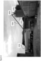
- Figure 9 shows another embodiment of an arrangement for automated logical coupling of a trailer to a silo, in combination with the principle of airflow exhaust of a silo, in accordance with the invention.
- a trailer A is depicted having bulk goods in its compartments 4, 5 being transported. These bulk goods, e.g. grain, flour, flakes, husks are to be delivered for example at a farm into silo 1.
- the silo 1 comprises a silo inlet B, being provided onto all silos, and an air outlet D, not provided onto all silos, but for instance only available for 90% of the silos to be loaded.
- tube S, C are shown for conveying the bulk goods from the trailer A to the silo 1.
- tube S having a diameter of for instance 90 - 100mm and for example being made of rubber, possibly foldable and transparent, is represented as the long hose between the trailer A and the silo 1
- tube C is rather a connection part between the long conveying route followed by tube S and the silo inlet B.
- wireless communication is present between trailer A and silo 1.
- Such wireless communication is for example characterized by a tag-reader system, i.e. a tag provided on silo 1 is in communication with or is read by a reader provided on trailer A.
- a go can be given for release of the material. It is noted that, according to the embodiment, such confirmation is enabled by silo detection on one hand, and airflow detection on the other hand.
- silo detection is meant that a fit of the correct silo with the correct trailer, hence for delivering correct goods, can be given based firstly on wireless communication e.g. by means of tag and reader. Secondly, correct delivery of goods is further affirmed by means of airflow detection, indicating whether or not airflows present, and hence whether or not the connection of trailer with silo is justified for delivery of the correct goods.
- the maximum operating pressure in the trailer is for example 2Bar, and thus also for the goods being transferred to the silo.
- the maximum air volume capacity through the loading tube can be for instance 1500m 3 /h. in case of air mixed with goods, this capacity will of course be lower.
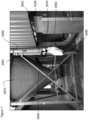
- FIG. 10 shows an embodiment of a bulk load station for loading a trailer transporting material to be transferred to a silo, in accordance with the invention.
- a bulk load station is provided at a bulk factory 3000 where bulk goods are stored and deposited in trailers 3030, to be delivered to silos 3010 at remote locations.
- a computer 3300 is provided with the bulk load station wherein information is kept regarding the preloading process, meaning the way the trailers 3030 need to be loaded in advance, for releasing afterwards correct goods in required weight and volume to the correct silos 3010.
- the identification of which compartment of the trailer needs to supplied with what kind of material, and how much of it, is controlled by means of the computer 3300. It is noted that a tag-reader system could also be used for the identification process.
- the trailer 3030 can leave the bulk factory 3000, and drive to the one or more different storage facilities and/or silos 3010 for delivering the bulk goods it is carrying.
- the trailer 3030 is provided with a track a trace system, meaning that the trailer 3030 can be traced or followed.
- a real-time communication is present between the bulk factory 3000 and the trailer 3030 where it has been loaded by means of the bulk load station.
- On the trailer 3030 itself there is also communication provided, in particular via RS232 between the trailer PLC system and the trailer base system, for reading or transferring data. Whenever the trailer 3030 reaches one of his destinations, the discharging process can be initiated.
- the silo 3010 wherein the goods have to be transferred is provided with a tag.
- a wireless reader provided on the trailer is brought in communication and connection with the tag. The reader then reads the tag, and detects airflow in the tube of the silo 3010 onto which the tag is mounted. While initiating airflow detection, a signal can be given to trailer chauffeur to start the compressor of the trailer 3030, and hence give an air pulse to the loading tubes and the hoses, such that air is blown through the silo 3010 including tubes and hoses. In case of airflow detection, there is certainty that correct trailer compartment G is connected with the right silo 3010.
- the information read out by the reader including regarding airflow detection is wirelessly submitted to the trailer base station of the trailer 3030 by means of LoRa communication.
- the trailer base station is in direct communication with the trailer PLC system via RS232
- the information can be visualized by means of the PLC user interface or controller console in the control box at the back of the trailer 3030.
- the trailer PLC system knows what is to be delivered where, and in what amount, the information from the silo side, as read by the reader at the trailer side, can be compared with the information at the trailer side, and thus give a release 'go' for transferring the correct bulk goods from compartment G of the trailer 3030 to the silo 3010. In case there is no match read by the reader out of the tag and/or there is no airflow detected, there will be no release, and thus a 'no go', for delivering the goods.
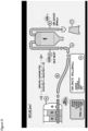
- FIG 11 shows an embodiment of a control system user interface 660 for visualizing material as stored in a compartment 625 of a trailer 620 to be released to the one of the appropriate silos 610, in accordance with the invention.
- the material is conveyed from trailer 620 to silo 610 by means of a tube 630, herewith connected with the inlet of the silo 610, onto which a tag 615 is mounted.
- a reader can read the tag 615.
- the information from the tag 615 is thus wirelessly communicated 640 with the trailer 620, more in particular a connection 650 is herewith made with the PLC system and corresponding user interface 660 of the trailer 620.
- PLC system is in direct connection with he trailer base station via RS232.
- the arrow 670 indicating the zoom out of the PLC user interface 660, which is provided on the back of the trailer 620 together with or integrated with the control box 680. Only one light 685 is lit up of the control box 680, meaning that only the first compartment 625 of the trailer 620 can be released or unloaded. In case for instance that two lights are lit up, this would imply that two compartments of the trailer 620 can be unloaded.
- the lights are in fact an indication for which surface valves can be activated, for opening the compartment and hence releasing material.
- FIG 12 shows an embodiment of tag 720 and reader 700 for automated logical coupling of a trailer to a silo, in accordance with the invention.
- FIG 12 (a) both tag 720 and reader 700 are shown, wherein the tag 720 is mounted or hung up onto a tube 900 of a silo by means of belts 800. Within the tag 720, a hole 725 is provided that can be closed by means of the plug 850 hanging onto one of the belts 800 with a cord.
- Both tag 720 and reader 700 are shown is perspective front view. Onto the front surface of the reader 700, are also provided a large circular LED indication 715 for indicating airflow detection and a series of small LED indications 710 for indicating positive tag-reader connection (meaning that correct coupling is made).
- tag 720 and reader 700 are shown in back perspective view.
- the NFC tag component 730 is illustrated.
- a hook or bracket system 740 is viewed, for hooking the reader 700 onto the tag 720.
- the backside of the reader 700 is provided with a protrusion 790 to be protruded into the hole 725 of the tag 720.
- a sensor 780 for airflow detection is further protruding, although not shown in Figure 12 (b) , being visible in Figure 12 (c) .
- an opening is provided at the height of the hole 725 and protrusion 790, out of which sensor 780 is protruding.
- the sensor 780 is herewith brought into the tube, for detecting airflow therein.
- Figure 12 (c) are shown part of the inner components of the reader 700, such as for example the LoRa antenna 750, battery 755, the NFC antenna 760, a PCB 765 and a wireless charging antenna 770.
- Figure 13 shows an embodiment of the working principle of tag-and-reader system for automated logical coupling of a trailer to a silo, in accordance with the invention.
- Figure 13 (a) is shown how the reader 700 can be hooked onto the tag 720 in the direction of the arrow A.
- the sensor 780 for airflow detection protruding out of the reader 700 is thus brought into the tube 900 while the reader 700 gets connected (in wireless communication) with the tag 720.
- LED indications 710', 715' are both lit up, indicating herewith that both airflow detection and tag-reader connection have succeeded with positive outcome, meaning that coupling of trailer with silo is correct, and thus material or bulk goods can be transferred from trailer to silo.
- FIG 14 shows an embodiment of a sensing system for detecting airflow in an arrangement for automated logical coupling of a trailer to a silo in accordance with the invention.
- the sensing system 1800 is for example a flex sensor or bend sensor, provided with an elastic protective sleeve 1840 to be provided within the reader assembly. Whenever reader is mounted or brought onto tag, the sensor is placed in the filling or dust pipe. The reader can be placed on either the filling pipe or dust pipe.
- the sleeve 1840 wherein the sensing component 1850 is embedded will bend due to the airflow and herewith causing vibrations.
- the bend sensor component is coupled to a wire connection 1860 or PCB with which a frequency, or ohm value, or else voltage or ADC values are registered. Subsequently, based on the values registered, a confirmation is sent to the trailer via a LoRa device that airflow was detected.
- a flex sensor or bend sensor an accelerometer, or a tilt ball sensor could also be used or airflow detection.
- possible dimensions of the sensor 1800 are illustrated with Figure 14 .
- Figure 15 shows a graphical representation of the airflow as detected in an arrangement for automated logical coupling of a trailer to a silo in accordance with the invention. Bending or flexing of the sensor causes a change in value of e.g. resistance or voltage, or ADC value, which is illustrated with Figure 15.
- ADC value e.g. resistance or voltage
- Left in the graph is the moment that the compressor of the trailer is put on, and hence airflow is brought into the tube or air exhaust.
- Peak values 1520 indicate airflow present in the tube. Turning off the compressor will take away the airflow pressure, and hence a decrease 1530 in ADC value can be measured until the low level 1540 is reached.
- a second increase 1550 turning on the compressor again, is also illustrated.
Landscapes
- Engineering & Computer Science (AREA)
- Mechanical Engineering (AREA)
- Aviation & Aerospace Engineering (AREA)
- Filling Or Emptying Of Bunkers, Hoppers, And Tanks (AREA)
Applications Claiming Priority (2)
| Application Number | Priority Date | Filing Date | Title |
|---|---|---|---|
| BE2018/5241A BE1025760B1 (nl) | 2018-04-10 | 2018-04-10 | Inrichting voor geautomatiseerde logische koppelingen aan trailer compartimenten |
| EP19168540.3A EP3599194B1 (de) | 2018-04-10 | 2019-04-10 | Anordnung zur automatisierten logischen kopplung an anhängerabteilen |
Related Parent Applications (2)
| Application Number | Title | Priority Date | Filing Date |
|---|---|---|---|
| EP19168540.3A Division EP3599194B1 (de) | 2018-04-10 | 2019-04-10 | Anordnung zur automatisierten logischen kopplung an anhängerabteilen |
| EP19168540.3A Division-Into EP3599194B1 (de) | 2018-04-10 | 2019-04-10 | Anordnung zur automatisierten logischen kopplung an anhängerabteilen |
Publications (2)
| Publication Number | Publication Date |
|---|---|
| EP4375219A2 true EP4375219A2 (de) | 2024-05-29 |
| EP4375219A3 EP4375219A3 (de) | 2024-08-21 |
Family
ID=62845889
Family Applications (2)
| Application Number | Title | Priority Date | Filing Date |
|---|---|---|---|
| EP24169947.9A Pending EP4375219A3 (de) | 2018-04-10 | 2019-04-10 | Anordnung zur automatisierten logischen kopplung an anhängerabteile |
| EP19168540.3A Active EP3599194B1 (de) | 2018-04-10 | 2019-04-10 | Anordnung zur automatisierten logischen kopplung an anhängerabteilen |
Family Applications After (1)
| Application Number | Title | Priority Date | Filing Date |
|---|---|---|---|
| EP19168540.3A Active EP3599194B1 (de) | 2018-04-10 | 2019-04-10 | Anordnung zur automatisierten logischen kopplung an anhängerabteilen |
Country Status (2)
| Country | Link |
|---|---|
| EP (2) | EP4375219A3 (de) |
| BE (1) | BE1025760B1 (de) |
Family Cites Families (8)
| Publication number | Priority date | Publication date | Assignee | Title |
|---|---|---|---|---|
| JPS59114217A (ja) * | 1982-12-22 | 1984-07-02 | Mitsubishi Heavy Ind Ltd | 真空輸送装置 |
| NL8602148A (nl) * | 1986-08-25 | 1988-03-16 | Nedap Nv | Identificatie ten behoeve van het laden en lossen van tankwagens. |
| JP3274260B2 (ja) * | 1993-10-29 | 2002-04-15 | 富士写真フイルム株式会社 | 溶液供給配管自動切替装置 |
| DE19750950C2 (de) * | 1997-09-22 | 2001-06-13 | Bartec Componenten & Syst Gmbh | Verfahren zum Sichern eines fließfähigen Guts und Sicherungssystem |
| US6347723B1 (en) * | 1997-09-22 | 2002-02-19 | Bartec Componenten Und Systeme Gmbh | Method and security system for securing a flowable good |
| CA2904777C (en) * | 2012-11-08 | 2023-04-04 | Delaware Capital Formation, Inc. | Cross contamination control systems with fluid product id sensors |
| EE201400033A (et) * | 2014-08-23 | 2016-05-16 | Nordic Automation Systems As | Pneumotööriista aktiivne kiirliitmik |
| JP6587482B2 (ja) * | 2015-09-29 | 2019-10-09 | 宇部三菱セメント株式会社 | 誤接続防止システム |
-
2018
- 2018-04-10 BE BE2018/5241A patent/BE1025760B1/nl active IP Right Grant
-
2019
- 2019-04-10 EP EP24169947.9A patent/EP4375219A3/de active Pending
- 2019-04-10 EP EP19168540.3A patent/EP3599194B1/de active Active
Also Published As
| Publication number | Publication date |
|---|---|
| BE1025760B1 (nl) | 2019-07-03 |
| EP4375219A3 (de) | 2024-08-21 |
| EP3599194B1 (de) | 2026-03-11 |
| EP3599194A8 (de) | 2025-05-07 |
| EP3599194C0 (de) | 2026-03-11 |
| EP3599194A3 (de) | 2020-02-19 |
| EP3599194A2 (de) | 2020-01-29 |
Similar Documents
| Publication | Publication Date | Title |
|---|---|---|
| US11424491B2 (en) | Battery and a system for swapping and/or charging a battery of a mobile robot | |
| US7999680B2 (en) | Safety equipment for freight loading and unloading docks | |
| US20150186837A1 (en) | Connection Line Protection System | |
| KR20170020155A (ko) | 배송 환경 정보 및 위치 정보를 수집하고 기록하는 리더 로거 장치 및 배송 정보 관리 시스템 | |
| JP2007511951A (ja) | コンテナ情報送出システム及びコンテナ追跡システム | |
| CN102105896A (zh) | 具有安装于一叉车叉齿的射频识别读取器的智能物流系统 | |
| EP3953276B1 (de) | Verwaltungssystem für logistikeinrichtungen | |
| JP2018163415A (ja) | 搬送システム、搬送方法、および自動搬送車 | |
| JP2018512830A (ja) | 産業機器用ワイヤレスパワー伝送及び通信 | |
| US20100302009A1 (en) | Data exchange with an m2m device using short range radio communication | |
| CN107531431A (zh) | 用于气动输送的压差检验法 | |
| US7013197B2 (en) | Climatic cabinet and device and method for its monitoring | |
| US11803215B2 (en) | Removable display and control module for a measuring device | |
| US20160240018A1 (en) | System and method for tracking a moveable asset transported by a vehicle | |
| EP3837567B1 (de) | Gehäuse mit uwb-sensor | |
| EP3992591B1 (de) | Detektionsvorrichtung für eine behälterbefüllung | |
| EP3599194B1 (de) | Anordnung zur automatisierten logischen kopplung an anhängerabteilen | |
| CN106274986A (zh) | 车载监控终端及铁路运输安全监控系统 | |
| US11029603B2 (en) | Chemical replacement system | |
| CN107075595A (zh) | 用于追踪容器、特别是冶金容器的金属工业设施及方法 | |
| CN106960296A (zh) | 基于智能货舱的运载工具货运执行方法及智能货舱 | |
| CN115180431A (zh) | 一种港口漏斗无人装粮系统及其控制方法 | |
| CN211827009U (zh) | 一种基于rfid的智慧工厂物料管理系统 | |
| CN206400620U (zh) | 一种基于rfid技术的出入库管理系统 | |
| US20230415288A1 (en) | Docking station for a workpiece holder in a driverless transport system |
Legal Events
| Date | Code | Title | Description |
|---|---|---|---|
| PUAI | Public reference made under article 153(3) epc to a published international application that has entered the european phase |
Free format text: ORIGINAL CODE: 0009012 |
|
| STAA | Information on the status of an ep patent application or granted ep patent |
Free format text: STATUS: THE APPLICATION HAS BEEN PUBLISHED |
|
| AC | Divisional application: reference to earlier application |
Ref document number: 3599194 Country of ref document: EP Kind code of ref document: P |
|
| AK | Designated contracting states |
Kind code of ref document: A2 Designated state(s): AL AT BE BG CH CY CZ DE DK EE ES FI FR GB GR HR HU IE IS IT LI LT LU LV MC MK MT NL NO PL PT RO RS SE SI SK SM TR |
|
| PUAL | Search report despatched |
Free format text: ORIGINAL CODE: 0009013 |
|
| AK | Designated contracting states |
Kind code of ref document: A3 Designated state(s): AL AT BE BG CH CY CZ DE DK EE ES FI FR GB GR HR HU IE IS IT LI LT LU LV MC MK MT NL NO PL PT RO RS SE SI SK SM TR |
|
| RIC1 | Information provided on ipc code assigned before grant |
Ipc: B65G 67/02 20060101ALI20240715BHEP Ipc: B65G 65/00 20060101ALI20240715BHEP Ipc: B65G 67/06 20060101ALI20240715BHEP Ipc: B65G 43/02 20060101AFI20240715BHEP |
|
| STAA | Information on the status of an ep patent application or granted ep patent |
Free format text: STATUS: REQUEST FOR EXAMINATION WAS MADE |
|
| 17P | Request for examination filed |
Effective date: 20250220 |
|
| STAA | Information on the status of an ep patent application or granted ep patent |
Free format text: STATUS: EXAMINATION IS IN PROGRESS |
|
| 17Q | First examination report despatched |
Effective date: 20250414 |