EP4374993A1 - Additive manufacturing build removal device and system - Google Patents
Additive manufacturing build removal device and system Download PDFInfo
- Publication number
- EP4374993A1 EP4374993A1 EP23210595.7A EP23210595A EP4374993A1 EP 4374993 A1 EP4374993 A1 EP 4374993A1 EP 23210595 A EP23210595 A EP 23210595A EP 4374993 A1 EP4374993 A1 EP 4374993A1
- Authority
- EP
- European Patent Office
- Prior art keywords
- build
- receptacle
- additive manufacturing
- panel
- base
- Prior art date
- Legal status (The legal status is an assumption and is not a legal conclusion. Google has not performed a legal analysis and makes no representation as to the accuracy of the status listed.)
- Pending
Links
Images





Classifications
-
- B—PERFORMING OPERATIONS; TRANSPORTING
- B22—CASTING; POWDER METALLURGY
- B22F—WORKING METALLIC POWDER; MANUFACTURE OF ARTICLES FROM METALLIC POWDER; MAKING METALLIC POWDER; APPARATUS OR DEVICES SPECIALLY ADAPTED FOR METALLIC POWDER
- B22F12/00—Apparatus or devices specially adapted for additive manufacturing; Auxiliary means for additive manufacturing; Combinations of additive manufacturing apparatus or devices with other processing apparatus or devices
- B22F12/80—Plants, production lines or modules
- B22F12/88—Handling of additively manufactured products, e.g. by robots
-
- B—PERFORMING OPERATIONS; TRANSPORTING
- B22—CASTING; POWDER METALLURGY
- B22F—WORKING METALLIC POWDER; MANUFACTURE OF ARTICLES FROM METALLIC POWDER; MAKING METALLIC POWDER; APPARATUS OR DEVICES SPECIALLY ADAPTED FOR METALLIC POWDER
- B22F10/00—Additive manufacturing of workpieces or articles from metallic powder
- B22F10/60—Treatment of workpieces or articles after build-up
- B22F10/68—Cleaning or washing
-
- B—PERFORMING OPERATIONS; TRANSPORTING
- B22—CASTING; POWDER METALLURGY
- B22F—WORKING METALLIC POWDER; MANUFACTURE OF ARTICLES FROM METALLIC POWDER; MAKING METALLIC POWDER; APPARATUS OR DEVICES SPECIALLY ADAPTED FOR METALLIC POWDER
- B22F12/00—Apparatus or devices specially adapted for additive manufacturing; Auxiliary means for additive manufacturing; Combinations of additive manufacturing apparatus or devices with other processing apparatus or devices
- B22F12/30—Platforms or substrates
-
- B—PERFORMING OPERATIONS; TRANSPORTING
- B29—WORKING OF PLASTICS; WORKING OF SUBSTANCES IN A PLASTIC STATE IN GENERAL
- B29C—SHAPING OR JOINING OF PLASTICS; SHAPING OF MATERIAL IN A PLASTIC STATE, NOT OTHERWISE PROVIDED FOR; AFTER-TREATMENT OF THE SHAPED PRODUCTS, e.g. REPAIRING
- B29C64/00—Additive manufacturing, i.e. manufacturing of three-dimensional [3D] objects by additive deposition, additive agglomeration or additive layering, e.g. by 3D printing, stereolithography or selective laser sintering
- B29C64/30—Auxiliary operations or equipment
- B29C64/35—Cleaning
-
- B—PERFORMING OPERATIONS; TRANSPORTING
- B29—WORKING OF PLASTICS; WORKING OF SUBSTANCES IN A PLASTIC STATE IN GENERAL
- B29C—SHAPING OR JOINING OF PLASTICS; SHAPING OF MATERIAL IN A PLASTIC STATE, NOT OTHERWISE PROVIDED FOR; AFTER-TREATMENT OF THE SHAPED PRODUCTS, e.g. REPAIRING
- B29C64/00—Additive manufacturing, i.e. manufacturing of three-dimensional [3D] objects by additive deposition, additive agglomeration or additive layering, e.g. by 3D printing, stereolithography or selective laser sintering
- B29C64/30—Auxiliary operations or equipment
- B29C64/379—Handling of additively manufactured objects, e.g. using robots
-
- B—PERFORMING OPERATIONS; TRANSPORTING
- B33—ADDITIVE MANUFACTURING TECHNOLOGY
- B33Y—ADDITIVE MANUFACTURING, i.e. MANUFACTURING OF THREE-DIMENSIONAL [3D] OBJECTS BY ADDITIVE DEPOSITION, ADDITIVE AGGLOMERATION OR ADDITIVE LAYERING, e.g. BY 3D PRINTING, STEREOLITHOGRAPHY OR SELECTIVE LASER SINTERING
- B33Y40/00—Auxiliary operations or equipment, e.g. for material handling
- B33Y40/20—Post-treatment, e.g. curing, coating or polishing
-
- B—PERFORMING OPERATIONS; TRANSPORTING
- B22—CASTING; POWDER METALLURGY
- B22F—WORKING METALLIC POWDER; MANUFACTURE OF ARTICLES FROM METALLIC POWDER; MAKING METALLIC POWDER; APPARATUS OR DEVICES SPECIALLY ADAPTED FOR METALLIC POWDER
- B22F10/00—Additive manufacturing of workpieces or articles from metallic powder
- B22F10/20—Direct sintering or melting
- B22F10/28—Powder bed fusion, e.g. selective laser melting [SLM] or electron beam melting [EBM]
-
- B—PERFORMING OPERATIONS; TRANSPORTING
- B22—CASTING; POWDER METALLURGY
- B22F—WORKING METALLIC POWDER; MANUFACTURE OF ARTICLES FROM METALLIC POWDER; MAKING METALLIC POWDER; APPARATUS OR DEVICES SPECIALLY ADAPTED FOR METALLIC POWDER
- B22F10/00—Additive manufacturing of workpieces or articles from metallic powder
- B22F10/70—Recycling
- B22F10/73—Recycling of powder
-
- B—PERFORMING OPERATIONS; TRANSPORTING
- B29—WORKING OF PLASTICS; WORKING OF SUBSTANCES IN A PLASTIC STATE IN GENERAL
- B29C—SHAPING OR JOINING OF PLASTICS; SHAPING OF MATERIAL IN A PLASTIC STATE, NOT OTHERWISE PROVIDED FOR; AFTER-TREATMENT OF THE SHAPED PRODUCTS, e.g. REPAIRING
- B29C64/00—Additive manufacturing, i.e. manufacturing of three-dimensional [3D] objects by additive deposition, additive agglomeration or additive layering, e.g. by 3D printing, stereolithography or selective laser sintering
- B29C64/10—Processes of additive manufacturing
- B29C64/141—Processes of additive manufacturing using only solid materials
- B29C64/153—Processes of additive manufacturing using only solid materials using layers of powder being selectively joined, e.g. by selective laser sintering or melting
-
- B—PERFORMING OPERATIONS; TRANSPORTING
- B29—WORKING OF PLASTICS; WORKING OF SUBSTANCES IN A PLASTIC STATE IN GENERAL
- B29C—SHAPING OR JOINING OF PLASTICS; SHAPING OF MATERIAL IN A PLASTIC STATE, NOT OTHERWISE PROVIDED FOR; AFTER-TREATMENT OF THE SHAPED PRODUCTS, e.g. REPAIRING
- B29C64/00—Additive manufacturing, i.e. manufacturing of three-dimensional [3D] objects by additive deposition, additive agglomeration or additive layering, e.g. by 3D printing, stereolithography or selective laser sintering
- B29C64/30—Auxiliary operations or equipment
- B29C64/357—Recycling
-
- B—PERFORMING OPERATIONS; TRANSPORTING
- B33—ADDITIVE MANUFACTURING TECHNOLOGY
- B33Y—ADDITIVE MANUFACTURING, i.e. MANUFACTURING OF THREE-DIMENSIONAL [3D] OBJECTS BY ADDITIVE DEPOSITION, ADDITIVE AGGLOMERATION OR ADDITIVE LAYERING, e.g. BY 3D PRINTING, STEREOLITHOGRAPHY OR SELECTIVE LASER SINTERING
- B33Y10/00—Processes of additive manufacturing
-
- B—PERFORMING OPERATIONS; TRANSPORTING
- B33—ADDITIVE MANUFACTURING TECHNOLOGY
- B33Y—ADDITIVE MANUFACTURING, i.e. MANUFACTURING OF THREE-DIMENSIONAL [3D] OBJECTS BY ADDITIVE DEPOSITION, ADDITIVE AGGLOMERATION OR ADDITIVE LAYERING, e.g. BY 3D PRINTING, STEREOLITHOGRAPHY OR SELECTIVE LASER SINTERING
- B33Y30/00—Apparatus for additive manufacturing; Details thereof or accessories therefor
-
- Y—GENERAL TAGGING OF NEW TECHNOLOGICAL DEVELOPMENTS; GENERAL TAGGING OF CROSS-SECTIONAL TECHNOLOGIES SPANNING OVER SEVERAL SECTIONS OF THE IPC; TECHNICAL SUBJECTS COVERED BY FORMER USPC CROSS-REFERENCE ART COLLECTIONS [XRACs] AND DIGESTS
- Y02—TECHNOLOGIES OR APPLICATIONS FOR MITIGATION OR ADAPTATION AGAINST CLIMATE CHANGE
- Y02P—CLIMATE CHANGE MITIGATION TECHNOLOGIES IN THE PRODUCTION OR PROCESSING OF GOODS
- Y02P10/00—Technologies related to metal processing
- Y02P10/25—Process efficiency
Definitions
- AM additive manufacturing
- EBM electron beam melting
- the fabricated in-process components and powder unused during fabrication need to be removed from the AM machine, e.g., EBM machine, and recovered in a safe and effective manner. This recovery process often requires significant downtime to allow the AM machine to cool down before a technician can manually remove a fabricated build structure.
- One removal device involves a collecting box placed in a molding apparatus to hold fabricated build structures including components and excess powder, which are later removed with a cart and transported to a powder recovery system.
- This removal device is limited because the box is used during the fabrication process and is thus exposed to the environmental conditions of the molding apparatus. Moreover, the box only works with machines specifically configured to accommodate it. Therefore, further improvements are needed for safely and efficiently removing and transferring fabricated build structures for post-processing.
- a build removal tool and a receptacle with a base and a panel may include a rotatable frame roller attached to the frame configured for the removal and transport an in-process fused powder build structure from an AM machine for post-processing without direct contact by the user with the build structure.
- the build removal tool and receptacle may be configured to work in tandem.
- the build removal tool may be used to transfer the build structure to the receptacle, e.g., by pulling out the build structure from the AM machine and sliding the build structure over the frame of the receptacle and into an enclosure of the receptacle.
- the receptacle may retain the build structure during transportation of the build structure and any excess powder that becomes separated from the build structure.
- the frame may include a cavity that may be configured to capture and retain excess powder during the transfer of the build structure to the receptacle from the AM machine, which allows for efficient conservation of build materials such as costly metal powders, e.g., but not limited to, titanium or titanium alloy powder.
- the receptacle may have a latching mechanism that may be configured to securely attach the panel, e.g., the frame of the panel, to the base to prevent rotation of the panel until the latching mechanism is unlatched. In this manner, the build structure and any excess powder from the build structure may be reliably transported in the receptacle without falling out.
- the receptacle may have handles that extend from opposing walls of the base and thereby are configured for use in manually lifting and moving the receptacle.
- the handles may be configured to reinforce either one of or both walls of the base from which the handles may extend. In this manner, the receptacle may be configured to hold heavier build structures than a similar receptacle without such handles.
- an AM machine may be configured with a removable build plate such that a build plate with a build structure fabricated on the build plate may be removable from the AM machine upon completion, or even during fabrication as needed, of the build structure and replaced with a clean build plate.
- a removable build plate such that a build plate with a build structure fabricated on the build plate may be removable from the AM machine upon completion, or even during fabrication as needed, of the build structure and replaced with a clean build plate.
- Such a configuration may reduce AM machine downtime between builds as a clean build plate from the stack replaces the previous one. This further improves the efficiency and safety as it affords technicians the ability to quickly remove and relocate to a safer environment (e.g., but not limited to, an oxygen-free environment) before prying the build structure off the removable build plate.
- a safer environment e.g., but not limited to, an oxygen-free environment
- a receptacle for use in the retention and transfer of an in-process fused powder build structure from an AM machine may include a base and a panel.
- the base may include a bottom surface
- the panel may include a frame and one or more rollers that may extend from the frame.
- the frame may be attached or attachable to the base such that the panel may be moveable between a first position in which a top surface of the roller lies in a first plane parallel to a second plane defined by the bottom surface of the base and a second position in which the panel and the base surround the build structure when the build structure is retained by the receptacle.
- the first plane and the second plane may be coplanar.
- the frame may be extended beneath and along a length of each of the one or more rollers.
- the frame may be configured to catch powder from the build structure.
- this frame configuration may be such that the powder may be caught while the frame is in the first position. Once captured, the frame may further be configured to retain the captured powder even after the frame is moved to the second position.
- the panel may be a door in which the door may further include a hinge.
- the frame may attach to the base such that the panel may be rotated between the first position and the second position.
- a stopper may be attached to the base or the panel.
- the stopper may be configured to prevent the panel from rotating beyond the first position and thereby may be configured to prevent rotation of the panel away from the base beyond a position in which the first plane and the second plane are coplanar.
- the base and the panel may be configured to additionally prevent the frame from rotating towards the base and past the second position.
- the receptacle may further include a first flange and a second flange on opposite sides of the panel.
- each of the first and the second flanges may be configured for placement on respective surfaces such that the first and the second flanges may support the receptacle.
- At least one location of the panel may be detachably attached to the base in second position by a latching mechanism.
- an AM system may include a receptacle according to any of the foregoing arrangements of the receptacle and a build removal tool for use in the removal of the build structure from a build plate in the AM machine.
- the build removal tool may have a shape such that the build removal tool may be configured to substantially correspond to a perimeter of a build structure such that the build removal tool may be placed over the build structure and may be configured to be slid along the roller and into the receptacle while retaining the build structure.
- the AM system may include a prying tool that may be configured to pry loose the build structure from a build plate of the AM machine on which the build structure is formed.
- a prying tool may be configured to pry loose the build structure from a build plate of the AM machine on which the build structure is formed.
- Such prying tool additionally may be used separately from the receptacle and the build removal tool.
- the build removal tool may include a wall that may define a notch.
- the prying tool may include a handle portion on one end and a wedge portion on an opposite end of the prying tool.
- the notch may then be configured for receiving and limiting movement of the wedge portion of the prying tool when the wedge portion is placed under the build removal tool and the handle portion is pressed downwardly against a build plate of the AM machine.
- the handle portion may cause an upward pivot movement of the wedge portion against the build structure when the handle portion is pressed downwardly against the build plate of the AM machine while the wedge portion is under the build structure.
- the notch may be located on the same side of the build removal tool from which the handle extends or otherwise a side of the build removal tool closest to the user.
- the build removal tool may include a plurality of walls in a rectangular shape defining the perimeter and may be configured to be placed around the build structure.
- the build removal tool may further include a handle extending from its walls.
- a first wall of the plurality of walls of the build removal tool may have a cutout that allows for passage of loose powder during the removal of the build structure from the build plate.
- the handle configured for use in pulling the build removal tool may extend from a second wall of the plurality of walls of the build removal tool opposite the first wall.
- the build removal tool according to any of the foregoing arrangements may be separate from the AM system.
- an AM machine may include a build plate configured such that a receptacle according to any of the foregoing arrangements defines a perimeter sufficient to surround the build structure when built on the build plate.
- the AM machine and the receptacle may be part of a system in which the receptacle may be configured for placement on the build plate such that no portion of the perimeter of the build structure extends beyond the build plate.
- an AM system may include a lifting mechanism and a receptacle according to any of the foregoing arrangements of the receptacle.
- the base of the receptacle may have a wall and a flange extending from the wall such that the flange may be configured for attachment to the lifting mechanism.
- the AM system may include an AM machine and a post-processing system that may be configured for separating one or more components from portions of the build structure unintended for further processing.
- the lifting mechanism may be moveable between a location adjacent to the AM machine and the post-processing system.
- the post-processing system may be a component recovery system configured for the separation of the one or more components from the portions of the build structure unintended for further processing.
- the component recovery system may be further configured as a powder recovery system configured for recovering powder removed from the build structure.
- an in-process build structure from an AM machine may be removed by a process.
- a build structure may be surrounded by the build removal tool, and the build removal tool may be pulled into a receptacle such that a bottom base of the receptacle overlaps a bottom opening defined by the build removal tool.
- the build structure may then be transported in the receptacle to a component recovery system.
- the build structure may be transported in the receptacle that may be supported by a lift crane.
- the receptacle may be supported by the lift crane.
- a first handle and a second handle of the receptacle may be supported by the lift crane.
- the build structure may be slid over a roller attached to the receptacle before the bottom base of the receptacle overlaps the bottom opening defined by the build removal tool.
- the build removal tool may include a handle that may extend from the build removal tool such that the pulling of the build removal tool may be performed by pulling the handle.
- loose powder captured by the build removal tool may be released through a cutout defined by the build removal tool during the pulling of the build removal tool into the receptacle.
- loose powder released through the cutout may be captured within a cavity defined by the panel.
- the receptacle may be attached to a delivery apparatus.
- the panel of the receptacle may be unlatched from the base of the receptacle such that the panel may be rotated away from the base to a position in which a plane defined by the panel may be substantially parallel to a plane defined by a build plate of the AM machine.
- the panel may be configured to rotate until a panel stopper attached to the panel of the receptacle contacts the base of the receptacle or until a base stopper contacts the panel.
- the build structure may be pried loose from the build plate of the AM machine, e.g., by a prying tool received through a notch defined by the build removal tool.
- a receptacle used for the retention and transfer of an in-process fused powder build structure from an AM machine may include a base and a panel.
- the base may include a base including a bottom surface and four walls extending from the base
- the panel may include a frame that may be rotatably attached to the base by a hinge such that the frame can rotate between a first position and a second position according to any of the foregoing arrangements of the first position and the second position.
- the frame may include a roller or a pair of rollers that extend from the frame and a cavity that extends beneath and along the length of the roller(s), such that the cavity may be configured to capture loose powder from a build structure slid into the receptacle.
- the frame may further include a stopper that may be positioned to prevent the frame from rotating beyond the first position.
- the base may additionally include a latching mechanism configured to detachably attach the frame to the base in at least one location.
- the base may further include a first flange, a second flange, and a third flange.
- the first flange and second flange may be on opposite sides of the receptacle and may be configured to support and/or reinforce the receptacle.
- the third flange may be located opposite of the panel and may be configured to attach to a lifting and/or transporting mechanism.
- an AM system may include a receptacle, a build removal tool, a prying tool, and a lifting and/or transporting mechanism.
- the receptacle may be according to any of the foregoing arrangements of the receptacle.
- the build removal tool may be configured for removing of a build structure from a build plate, such that the build removal tool may include a plurality of walls in a rectangular shape defining the perimeter to be placed around the build structure.
- the build removal tool may further include a handle extending from the walls situated to be pulled such that the build removal tool can slide the build structure along a roller and into the receptacle.
- the prying tool may be configured to pry loose the build structure from the build plate of the AM machine on which the build structure is formed.
- the lifting mechanism may be configured to lift and transport the build structure in the receptacle such that the third flange of the receptacle may be configured to for attachment to the lifting mechanism.
- an AM machine such as an EBM machine or a laser melting machine, e.g., a direct metal laser melting machine
- Examples described herein refer to instruments or systems of corresponding instruments that work in tandem.
- an AM system may include a receptacle, a build removal tool, a prying tool, and a delivery apparatus for transporting and lifting the receptacle and a build structure, which work in concert in the removal and transfer of a build structure from an AM machine.
- the use or non-use of any one of these components is not limited by the use or non-use of the other components as any of the components may be employed individually in the build removal process.
- receptacle 10 generally includes base 11 providing a bottom surface and side walls of the receptacle and panel 20 acting as a door for the receptacle. While receptacle 10 is shown as having a generally rectangular profile, receptacle 10 is not limited to having a particular profile and may have other geometric profiles, e.g., circular, triangular, etc. In some arrangements, receptacle 10 may be tailored to approximately the size of a build structure such that the size of receptacle 10 is appropriate hold an entire build structure without significant clearance in order to inhibit movement of the build structure during transport of the build structure. Alternatively, the size of receptacle 10 may correspond to the size of a build plate such that receptacle 10 is configured to hold the build plate in instances where the build plate is removable.
- receptacle 10 includes hinge mechanism 60 and panel 20 of receptacle 10 includes frame 22 attached to base 11 by the hinge mechanism such that the frame and thereby the panel rotates relative to the base.
- a width of frame 22, as taken in a direction perpendicular to a direction of entry of a build structure into the receptacle, and a height of the frame, as taken in a direction perpendicular to the width and to a thickness of the frame, may be congruent to the walls of panel 20, but the frame is not limited by shape or size although the frame preferably has a size and shape that retains excess powder that may separate from the build structure, in particular during transport of the receptacle.
- the dimensions of frame 22 may be determined, for example, by either one of or both the size of a build structure and a distance that build structure needs to travel to reach receptacle 10.
- frame 22 may be extendable and retractable such that the dimensions of frame 22 are variable.
- Panel 20 further includes a pair of rollers 24 extending across the width of frame 22, although in alternative arrangements, the panel may include only one roller or a greater number of rollers.
- Each roller 24 is attached to frame 22 such that the roller can freely rotate to facilitate sliding of objects, e.g., a build structure, over the roller and into and out of receptacle 10.
- each roller 24 has an elongated cylindrical shape, but the roller or plurality of rollers may be in other forms, e.g., spherical in which the roller may be one or more roller ball transfer bearings.
- roller ball transfer bearings multiple rollers may be placed in various configurations, such as but not limited to across the width of frame 22, over the area of the frame, or at the corners of the frame.
- the rollers 24 may be configured such that the top surface of the rollers 24 is slightly higher (i.e., farther from the ground) than the bottom surface of the base 11 when the panel 22 is in a horizontal position.
- frame 22 forms cavity 80 that extends beneath a full length of each roller 24 to provide a trough for collecting excess powder as a build structure is removed from an AM machine and slid over the rollers and into receptacle 10.
- costly materials e.g., metal powders such as but not limited to titanium and titanium alloy powders, may be conserved for later reuse in an AM machine in a safe and time efficient manner.
- panel 20 is configured to rotate between a first position, such as a fully open position as shown in FIG. 1 , and a second position, such as a fully closed position as shown in FIG. 2 , but the available positions of frame 22 are not limited to these two positions.
- first position is utilized to allow either one of or both a build structure or build plate to slide over rollers 24 and into receptacle 10.
- panel 20 may be rotated upward towards base 11 into the second position, and latching mechanism 70 may be employed to attach panel 20 to base 11.
- Latching mechanism 70 may include portions attached to or otherwise positioned on an interior or an exterior of receptacle 10, at adjacent locations of panel 20 and base 11 when the receptacle is in the closed position, so long as the latching mechanism does not interfere with the functionality of roller 24 or the entry of the build structure into the receptacle.
- latching mechanism 70 may be configured as spring clasps extending from the base 11 that hold the panel 20 fully closed.
- Latching mechanism 70 may be any other appropriate latching mechanism known to those skilled in the art, e.g., a hook-and-loop mechanism or opposing magnets.
- panel 20 When latching mechanism 70 is released, panel 20 may be rotated downward until stopped by stopper 50 attached to base 11.
- stopper 50 is a flange positioned to abut a portion of frame 22 when panel 20 is in the first position.
- a top or outer surface of rollers 24 are positioned in a plane parallel with the bottom surface of base 11 that defines a bottom of an interior region of receptacle 10 for receiving a build structure. Movement of panel 20 from the first position to the second position or vice versa may be manually performed by a user or automatically performed, e.g., by a coil spring in tension attached to both panel 20 and base 11 or by a motor attached to both the panel and the base as known to those skilled in the art.
- an electrical control panel may include buttons or a dial to select desired positions of the panel, and upon selection of a desired position, the motor may cause the panel to rotate to the desired position.
- receptacle 10 further includes side flanges 40 extending from base 11.
- side flanges 40 may be integral with base 11 such that the side flanges and the base form a one-piece structure that is inseparable without fracture of either one or both of the side flanges and the base.
- Side flanges 40 may be configured, e.g., bent, curled, or rolled, to provide support surfaces for lifting receptacle 10, and in some arrangements, for engagement with delivery apparatus 300 (see FIG. 6 ) for transporting and elevating the receptacle.
- side flanges 40 may be the same or different than the material for panel 20 and may be coated or covered with frictional material that provides grip and protection to the user while handling receptacle 10. Additionally, receptacle 10 may be reinforced by side flanges 40 to allow receptacle 10 to hold larger or even multiple build structures than the receptacle would hold without the side flanges, but reinforcement of receptacle 10 is not limited to the side flanges and may be accomplished by other means. In this manner, receptacle 10 may be able to safely transport build structures of various sizes and weights.
- build removal tool 200 used to remove a build structure from a build plate in an AM machine generally includes enclosure 210 and handle 220.
- enclosure 210 is formed by a plurality of walls sufficiently sized and configured to both surround the build structure and fit into an AM machine build chamber. In this manner, enclosure 210 may be placed over and around a build structure and utilized to slide the build structure out of the AM machine. Enclosure 210 may be further slid over roller 24 within frame 22 of panel 20 when the panel is in the first position and then received into receptacle 10.
- opposing walls 212a, 212b of enclosure 210 may extend beyond leading wall 213 of enclosure 210 to define opposing flanges between which handle 220 extends.
- Handle 220 may be used to facilitate the sliding of build removal tool 200, in particular when a build structure is surrounded by the build removal tool, by pulling handle 220. Utilizing build removal tool 200, a build structure can be removed relatively quickly from an AM machine at high temperatures without a user directly contacting the build structure or internal areas of the AM machine, e.g., the build plate.
- build removal tool 200 may include cutout 240 defined by trailing wall 214 having a shorter height than opposing walls 212a, 212b between which the trailing wall extends.
- build removal tool 200 may be configured to open and close cutout 240 as needed by moving a cutout cover. With either configuration, as build removal tool 200 is slid off the build plate, excess powder passes under cutout 240 of trailing wall 214 of build removal tool 200 and remains on the build plate. In this manner, time and resources are conserved by making the excess powder available for the next AM build without additional post-processing to capture the excess powder.
- notch 230 allows a prying tool, e.g., prying tool 400A, 400B, to access the build structure while build removal tool 200 surrounds the build structure.
- notch 230 allows prying tool 400A, 400B to be inserted into the interior region of build removal tool 200 such that prying tool 400A, 400B can pry the build structure loose from the build plate upon completion of a build structure or even prior to completion, e.g., as needed to remove a defective build structure.
- a prying tool e.g., prying tool 400A, 400B
- prying tool 400A may have a handle portion 410 on one end and a wedge portion 420A with a thin prying edge 422A on the opposite end in which a width of the wedge portion is less than a width of notch 230.
- prying tool 400B may otherwise be in the form of prying tool 400A and include tapered edges 430 defining edges of wedge portion 420B that extend from prying edge 422B of the wedge portion toward handle portion 410, as shown in FIG. 7B .
- the build structure may be pried loose from the build plate by placing wedge portion 420A, 420B through notch 230 on build removal tool 200 and then pressing downwardly on the handle portion 410 of the prying tool 400A, 400B against a build plate to create an upward pivot movement of the prying edge of the wedge portion 420A, 420B of the prying tool 400A, 400B.
- a technician may remove a build structure without directly contacting the build structure and thus avoid any need to wait until after the build structure has cooled sufficiently.
- tapered edges 430 reduces surface area at the front of prying tool 400B and thereby provides for easier insertion of prying tool 400B between the build structure and the build plate of the AM machine as well as provides regions for loose powder to fall away from the prying tool during removal of the build structure from the build plate.
- receptacle 10 is attachable to delivery apparatus 300 configured for either one of or both lifting and transporting the receptacle.
- apparatus 300 may be, but is not limited to being, a crane.
- Receptacle 10 includes back flange 30 (see FIGS. 1 and 2 ) that extends from leading wall 213 of base 11 that is opposite panel 20 when the panel is in a closed position.
- Back flange 30 is configured to provide an attachment port through which a flange of delivery apparatus 300 may be received such that receptacle 10 may be attached to apparatus 300, and as in the example shown, remain attached to the apparatus during either one of or both transporting and lifting the receptacle.
- Delivery apparatus 300 may be motorized or otherwise powered and, in some arrangements, may be controlled by an automated system. Once the build structure has been placed in receptacle 10, apparatus 300 may then transport receptacle 10 for post-processing, e.g., to a blasting chamber for removing excess powder from the build structure that may be recycled for future use by an AM machine.
- a build structure is removed from an AM system and transported for further processing according to process 500.
- a build removal tool e.g., build removal tool 200
- a build removal tool is placed over a build structure on a build plate of an AM machine to surround the build structure.
- the build structure and the build removal tool surrounding the build structure are removed from the build plate in the AM machine, e.g., by pulling on build removal 200 tool, such that both the build structure and the build removal tool slide into a receptacle, e.g., receptacle 10.
- a panel, e.g., panel 20, of the receptacle is rotated towards a base, e.g., base 11, of the receptacle and the panel is locked to the base, e.g., by latching panel 20 to base 11 of receptacle 10 with latching mechanism 70.
- the receptacle, e.g., receptacle 10 surrounding the build structure is transported to a post-processing system(s), e.g., by moving delivery apparatus 300 attached to the receptacle.
- process 500 allows for a fabricated build structure to be processed remotely from the AM machine to allow quicker fabrication of a subsequent build structure on the AM machine as well as to retain and recycle excess powder from the build structures when processing the build structures remotely from the AM machine.
- the build removal tool e.g., build removal tool 200
- the receptacle e.g., receptacle 10
- receptacle 110 includes all the same features and components as receptacle 10 with the addition of skirt mount 190 attached to base 111 such that the skirt mount extends along a length of the base between opposing stoppers 150.
- skirt mount 190 is fixed in position underneath the divide between the panel 120 and base 111 when the receptacle is in the closed and opened positions.
- the skirt mount is pivotably attached to receptacle 110 such that the skirt mount can pivot between a first position and second position, the first being a position in which the skirt mount extends underneath the divide (e.g., divide 195) between panel 120 and base 111 when the receptacle is in the closed position.
- skirt mount 190 is positioned sufficiently close to panel 120 to catch and collect excess powder that may fall between panel 120 and base 111 as the panel rotates between opened and closed positions (i.e., horizontal and vertical orientations).
- Skirt mount may include features to retain such powder such as a groove disposed therein or one or more sidewalls extending therefrom. In this manner, receptacle 111 captures and conserves valuable metal powder when used in additive manufacturing.
- a build plate may be configured to be removed from an AM machine and transported in a receptacle, e.g., one in the form of receptacle 10.
- the removable build plate upon completion of a build structure, would detach from the AM build machine and slide across roller 24 into receptacle 10 with the build structure still attached to the build plate.
- This arrangement may be used in conjunction with stackable build plates found in U.S. Patent 11,440,256 to Walsh et al. , which is hereby incorporated by reference herein in its entirety. Handles or tabs may be placed on the removable build plate to facilitate removal.
- a build removal tool e.g., one in the form of build removal tool 200, may be configured to attach to the removable build plate such that lifting and removing of the removable build plate is performed by lifting and pulling the build removal tool after the build removal tool has been attached to the removable build plate.
- a technician may employ the build removal tool to pull the removable build plate and the build structure attached to the removable build plate out of the AM machine and into receptacle 10. In this manner, the technician can relocate the combination build structure and build plate to a safer environment, e.g., an oxygen-free environment, for post-processing when dealing with highly flammable metal powders before prying the build structure from the removable build plate.
Landscapes
- Engineering & Computer Science (AREA)
- Chemical & Material Sciences (AREA)
- Manufacturing & Machinery (AREA)
- Materials Engineering (AREA)
- Robotics (AREA)
- Physics & Mathematics (AREA)
- Mechanical Engineering (AREA)
- Optics & Photonics (AREA)
Abstract
A receptacle [10] for use in the retention and transfer of an in-process fused powder build structure from an additive manufacturing machine includes a base [11] and a panel [20]. The base includes a bottom surface. The panel includes a frame [22] and a roller [24] extending from the frame. The frame is attached or attachable to the base such that the panel is moveable between a first position in which a top surface of the roller lies in a first plane parallel to a second plane defined by the bottom surface of the base and a second position in which the panel and the base surround the build structure when the build structure is retained by the receptacle.
Description
- In the field of additive manufacturing (AM), post-processing steps are often necessary but time consuming and costly. Some AM (i.e., three-dimensional printing) techniques, such as electron beam melting (EBM) processes, require the use of metallic powder, e.g., titanium or titanium alloy powder, which has relatively high material costs and requires careful processing as the powder is highly flammable in an oxygenated environment. AM processes such as EBM processes result in fused powder build structures made of desired components, which may be in-process components requiring further processing, and excess powder, which may include powder that was partially heated during the formation of the in-process components, surrounding the desired components. Following such processes, the fabricated in-process components and powder unused during fabrication need to be removed from the AM machine, e.g., EBM machine, and recovered in a safe and effective manner. This recovery process often requires significant downtime to allow the AM machine to cool down before a technician can manually remove a fabricated build structure.
- Efforts have been made to address such post-processing bottlenecks. For example, to eliminate the need for an AM machine to cool down before removing build structures, a clamping tool with teeth has been used in place of manual lifting. However, because the clamping tool crushes through excess powder surrounding fabricated components of a build structure, it is largely ineffective at lifting fabricated build structures and makes removal of such build structures even more time consuming when the clamping tool is unable to remove the build structure and a manual removal process is thus used in the alternative.
- Other devices have been developed to remove fabricated build structures. One removal device involves a collecting box placed in a molding apparatus to hold fabricated build structures including components and excess powder, which are later removed with a cart and transported to a powder recovery system. This removal device, however, is limited because the box is used during the fabrication process and is thus exposed to the environmental conditions of the molding apparatus. Moreover, the box only works with machines specifically configured to accommodate it. Therefore, further improvements are needed for safely and efficiently removing and transferring fabricated build structures for post-processing.
- In accordance with an aspect, a build removal tool and a receptacle with a base and a panel. The panel may include a rotatable frame roller attached to the frame configured for the removal and transport an in-process fused powder build structure from an AM machine for post-processing without direct contact by the user with the build structure. The build removal tool and receptacle may be configured to work in tandem. The build removal tool may be used to transfer the build structure to the receptacle, e.g., by pulling out the build structure from the AM machine and sliding the build structure over the frame of the receptacle and into an enclosure of the receptacle. The receptacle may retain the build structure during transportation of the build structure and any excess powder that becomes separated from the build structure. In this manner, the build structure may be safely and efficiently removed for post-processing, whether hot or cold, thus eliminating downtime to allow the AM machine to cool down. In some arrangements, the frame may include a cavity that may be configured to capture and retain excess powder during the transfer of the build structure to the receptacle from the AM machine, which allows for efficient conservation of build materials such as costly metal powders, e.g., but not limited to, titanium or titanium alloy powder.
- In some arrangements, the receptacle may have a latching mechanism that may be configured to securely attach the panel, e.g., the frame of the panel, to the base to prevent rotation of the panel until the latching mechanism is unlatched. In this manner, the build structure and any excess powder from the build structure may be reliably transported in the receptacle without falling out. In some arrangements, the receptacle may have handles that extend from opposing walls of the base and thereby are configured for use in manually lifting and moving the receptacle. In some arrangements, the handles may be configured to reinforce either one of or both walls of the base from which the handles may extend. In this manner, the receptacle may be configured to hold heavier build structures than a similar receptacle without such handles.
- In some arrangements, an AM machine may be configured with a removable build plate such that a build plate with a build structure fabricated on the build plate may be removable from the AM machine upon completion, or even during fabrication as needed, of the build structure and replaced with a clean build plate. Such a configuration may reduce AM machine downtime between builds as a clean build plate from the stack replaces the previous one. This further improves the efficiency and safety as it affords technicians the ability to quickly remove and relocate to a safer environment (e.g., but not limited to, an oxygen-free environment) before prying the build structure off the removable build plate.
- In another aspect, a receptacle for use in the retention and transfer of an in-process fused powder build structure from an AM machine may include a base and a panel. The base may include a bottom surface, and the panel may include a frame and one or more rollers that may extend from the frame. The frame may be attached or attachable to the base such that the panel may be moveable between a first position in which a top surface of the roller lies in a first plane parallel to a second plane defined by the bottom surface of the base and a second position in which the panel and the base surround the build structure when the build structure is retained by the receptacle. In some arrangements, the first plane and the second plane may be coplanar.
- In some arrangements, the frame may be extended beneath and along a length of each of the one or more rollers. In some such arrangements, the frame may be configured to catch powder from the build structure. In some arrangements, this frame configuration may be such that the powder may be caught while the frame is in the first position. Once captured, the frame may further be configured to retain the captured powder even after the frame is moved to the second position.
- In some arrangements, the panel may be a door in which the door may further include a hinge. In some arrangements, the frame may attach to the base such that the panel may be rotated between the first position and the second position.
- In some arrangements, a stopper may be attached to the base or the panel. In some such arrangements, the stopper may be configured to prevent the panel from rotating beyond the first position and thereby may be configured to prevent rotation of the panel away from the base beyond a position in which the first plane and the second plane are coplanar. In some arrangements, the base and the panel may be configured to additionally prevent the frame from rotating towards the base and past the second position.
- In some arrangements, the receptacle may further include a first flange and a second flange on opposite sides of the panel. In some such arrangements, each of the first and the second flanges may be configured for placement on respective surfaces such that the first and the second flanges may support the receptacle.
- In some arrangements, at least one location of the panel may be detachably attached to the base in second position by a latching mechanism.
- In accordance with another aspect, an AM system may include a receptacle according to any of the foregoing arrangements of the receptacle and a build removal tool for use in the removal of the build structure from a build plate in the AM machine. The build removal tool may have a shape such that the build removal tool may be configured to substantially correspond to a perimeter of a build structure such that the build removal tool may be placed over the build structure and may be configured to be slid along the roller and into the receptacle while retaining the build structure.
- In some arrangements, the AM system may include a prying tool that may be configured to pry loose the build structure from a build plate of the AM machine on which the build structure is formed. Such prying tool additionally may be used separately from the receptacle and the build removal tool.
- In some arrangements, the build removal tool may include a wall that may define a notch. In some such arrangements, the prying tool may include a handle portion on one end and a wedge portion on an opposite end of the prying tool. The notch may then be configured for receiving and limiting movement of the wedge portion of the prying tool when the wedge portion is placed under the build removal tool and the handle portion is pressed downwardly against a build plate of the AM machine. Additionally, the handle portion may cause an upward pivot movement of the wedge portion against the build structure when the handle portion is pressed downwardly against the build plate of the AM machine while the wedge portion is under the build structure. In some arrangements, the notch may be located on the same side of the build removal tool from which the handle extends or otherwise a side of the build removal tool closest to the user.
- In some arrangements, the build removal tool may include a plurality of walls in a rectangular shape defining the perimeter and may be configured to be placed around the build structure. The build removal tool may further include a handle extending from its walls. In some such arrangements, a first wall of the plurality of walls of the build removal tool may have a cutout that allows for passage of loose powder during the removal of the build structure from the build plate. In some such arrangements, the handle configured for use in pulling the build removal tool may extend from a second wall of the plurality of walls of the build removal tool opposite the first wall.
- In some arrangements, the build removal tool according to any of the foregoing arrangements may be separate from the AM system.
- In accordance with another aspect, an AM machine may include a build plate configured such that a receptacle according to any of the foregoing arrangements defines a perimeter sufficient to surround the build structure when built on the build plate. In some arrangements, the AM machine and the receptacle may be part of a system in which the receptacle may be configured for placement on the build plate such that no portion of the perimeter of the build structure extends beyond the build plate.
- In another aspect, an AM system may include a lifting mechanism and a receptacle according to any of the foregoing arrangements of the receptacle. In some such arrangements, the base of the receptacle may have a wall and a flange extending from the wall such that the flange may be configured for attachment to the lifting mechanism.
- In some arrangements, the AM system may include an AM machine and a post-processing system that may be configured for separating one or more components from portions of the build structure unintended for further processing. In some such arrangements, the lifting mechanism may be moveable between a location adjacent to the AM machine and the post-processing system. In some arrangements, the post-processing system may be a component recovery system configured for the separation of the one or more components from the portions of the build structure unintended for further processing. In some such arrangements, the component recovery system may be further configured as a powder recovery system configured for recovering powder removed from the build structure.
- In accordance with another aspect, an in-process build structure from an AM machine may be removed by a process. In the process, a build structure may be surrounded by the build removal tool, and the build removal tool may be pulled into a receptacle such that a bottom base of the receptacle overlaps a bottom opening defined by the build removal tool. Subsequently, the build structure may then be transported in the receptacle to a component recovery system.
- In some arrangements, the build structure may be transported in the receptacle that may be supported by a lift crane. In some arrangements, the receptacle may be supported by the lift crane. In some such arrangements, a first handle and a second handle of the receptacle may be supported by the lift crane.
- In some arrangements, the build structure may be slid over a roller attached to the receptacle before the bottom base of the receptacle overlaps the bottom opening defined by the build removal tool. In some arrangements, the build removal tool may include a handle that may extend from the build removal tool such that the pulling of the build removal tool may be performed by pulling the handle.
- In some arrangements, loose powder captured by the build removal tool may be released through a cutout defined by the build removal tool during the pulling of the build removal tool into the receptacle.
- In some arrangements, loose powder released through the cutout may be captured within a cavity defined by the panel.
- In some arrangements, the receptacle may be attached to a delivery apparatus.
- In some arrangements, the panel of the receptacle may be unlatched from the base of the receptacle such that the panel may be rotated away from the base to a position in which a plane defined by the panel may be substantially parallel to a plane defined by a build plate of the AM machine. In some arrangements, the panel may be configured to rotate until a panel stopper attached to the panel of the receptacle contacts the base of the receptacle or until a base stopper contacts the panel.
- In some arrangements, the build structure may be pried loose from the build plate of the AM machine, e.g., by a prying tool received through a notch defined by the build removal tool.
- In accordance with another aspect, a receptacle used for the retention and transfer of an in-process fused powder build structure from an AM machine may include a base and a panel. The base may include a base including a bottom surface and four walls extending from the base, and the panel may include a frame that may be rotatably attached to the base by a hinge such that the frame can rotate between a first position and a second position according to any of the foregoing arrangements of the first position and the second position. The frame may include a roller or a pair of rollers that extend from the frame and a cavity that extends beneath and along the length of the roller(s), such that the cavity may be configured to capture loose powder from a build structure slid into the receptacle. The frame may further include a stopper that may be positioned to prevent the frame from rotating beyond the first position. The base may additionally include a latching mechanism configured to detachably attach the frame to the base in at least one location. The base may further include a first flange, a second flange, and a third flange. The first flange and second flange may be on opposite sides of the receptacle and may be configured to support and/or reinforce the receptacle. The third flange may be located opposite of the panel and may be configured to attach to a lifting and/or transporting mechanism.
- In accordance with another aspect, an AM system may include a receptacle, a build removal tool, a prying tool, and a lifting and/or transporting mechanism. The receptacle may be according to any of the foregoing arrangements of the receptacle. The build removal tool may be configured for removing of a build structure from a build plate, such that the build removal tool may include a plurality of walls in a rectangular shape defining the perimeter to be placed around the build structure. The build removal tool may further include a handle extending from the walls situated to be pulled such that the build removal tool can slide the build structure along a roller and into the receptacle. In another aspect, the prying tool may be configured to pry loose the build structure from the build plate of the AM machine on which the build structure is formed. In another aspect, the lifting mechanism may be configured to lift and transport the build structure in the receptacle such that the third flange of the receptacle may be configured to for attachment to the lifting mechanism.
- A more complete appreciation of the subject matter of the present disclosure and the various advantages thereof may be realized by reference to the following detailed description which refers to the accompanying drawings, in which:
-
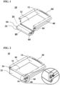
FIG. 1 is a perspective view of a receptacle for the retention and transfer of an in-process fused powder build structure from an AM machine, the receptacle being shown in an open position, in accordance with an aspect; -
FIG. 2 is a perspective view of the receptacle ofFIG. 1 , the receptacle being shown in a closed position; -
FIG. 3 is a rear view of the receptacle ofFIG. 1 ; -
FIG. 4 is a perspective view of a build removal tool in accordance with another aspect; -
FIGS. 5A and 5B are side and top views of the build removal tool ofFIG. 4 ; -
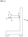
FIG. 6 is a side view of a delivery apparatus and the receptacle ofFIG. 1 that is attached to the delivery apparatus in accordance with another aspect; -
FIG. 7A is a perspective view of a prying tool in accordance with another aspect; -
FIG. 7B is a top view of a prying tool in accordance with another aspect; -
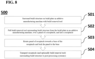
FIG. 8 is a process flow diagram of a process for removing a build structure from an AM machine and transporting the build structure for post-processing in accordance with another aspect; -
FIG. 9 is perspective view of a build removal tool received into a receptacle in accordance with another aspect; -
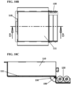
FIG. 10A is a perspective view of a receptacle having a skirt mount in accordance with another aspect of the present disclosure, the receptacle being shown in the closed position; and -
FIG. 10B is a top view of the receptacle ofFIG. 10A , the receptacle being shown in the opened position; and -
FIG. 10C is a cross-sectional side view of the receptacle ofFIG. 10B across line B-B. - The specific examples herein relate to the removal and transfer of an in-process fused powder build structure from an AM machine such as an EBM machine or a laser melting machine, e.g., a direct metal laser melting machine, for post-processing with the specific goal of making the removal and transfer processes safer and more efficient. Examples described herein refer to instruments or systems of corresponding instruments that work in tandem. For example, an AM system may include a receptacle, a build removal tool, a prying tool, and a delivery apparatus for transporting and lifting the receptacle and a build structure, which work in concert in the removal and transfer of a build structure from an AM machine. However, the use or non-use of any one of these components is not limited by the use or non-use of the other components as any of the components may be employed individually in the build removal process.
- Referring now to the drawings, as shown in
FIG. 1 ,receptacle 10 generally includesbase 11 providing a bottom surface and side walls of the receptacle andpanel 20 acting as a door for the receptacle. Whilereceptacle 10 is shown as having a generally rectangular profile,receptacle 10 is not limited to having a particular profile and may have other geometric profiles, e.g., circular, triangular, etc. In some arrangements,receptacle 10 may be tailored to approximately the size of a build structure such that the size ofreceptacle 10 is appropriate hold an entire build structure without significant clearance in order to inhibit movement of the build structure during transport of the build structure. Alternatively, the size ofreceptacle 10 may correspond to the size of a build plate such thatreceptacle 10 is configured to hold the build plate in instances where the build plate is removable. - In the example of
FIG. 1 ,receptacle 10 includeshinge mechanism 60 andpanel 20 ofreceptacle 10 includesframe 22 attached to base 11 by the hinge mechanism such that the frame and thereby the panel rotates relative to the base. A width offrame 22, as taken in a direction perpendicular to a direction of entry of a build structure into the receptacle, and a height of the frame, as taken in a direction perpendicular to the width and to a thickness of the frame, may be congruent to the walls ofpanel 20, but the frame is not limited by shape or size although the frame preferably has a size and shape that retains excess powder that may separate from the build structure, in particular during transport of the receptacle. The dimensions offrame 22 may be determined, for example, by either one of or both the size of a build structure and a distance that build structure needs to travel to reachreceptacle 10. Alternatively,frame 22 may be extendable and retractable such that the dimensions offrame 22 are variable. -
Panel 20 further includes a pair ofrollers 24 extending across the width offrame 22, although in alternative arrangements, the panel may include only one roller or a greater number of rollers. Eachroller 24 is attached to frame 22 such that the roller can freely rotate to facilitate sliding of objects, e.g., a build structure, over the roller and into and out ofreceptacle 10. In the example shown, eachroller 24 has an elongated cylindrical shape, but the roller or plurality of rollers may be in other forms, e.g., spherical in which the roller may be one or more roller ball transfer bearings. When using roller ball transfer bearings, multiple rollers may be placed in various configurations, such as but not limited to across the width offrame 22, over the area of the frame, or at the corners of the frame. Therollers 24 may be configured such that the top surface of therollers 24 is slightly higher (i.e., farther from the ground) than the bottom surface of the base 11 when thepanel 22 is in a horizontal position. As further shown, frame 22forms cavity 80 that extends beneath a full length of eachroller 24 to provide a trough for collecting excess powder as a build structure is removed from an AM machine and slid over the rollers and intoreceptacle 10. In this manner, costly materials e.g., metal powders such as but not limited to titanium and titanium alloy powders, may be conserved for later reuse in an AM machine in a safe and time efficient manner. - Referring now and comparing
FIGS. 1 and 2 ,panel 20 is configured to rotate between a first position, such as a fully open position as shown inFIG. 1 , and a second position, such as a fully closed position as shown inFIG. 2 , but the available positions offrame 22 are not limited to these two positions. When removing a build structure from an AM machine, the first position is utilized to allow either one of or both a build structure or build plate to slide overrollers 24 and intoreceptacle 10. After a build structure is fully received intoreceptacle 10,panel 20 may be rotated upward towardsbase 11 into the second position, and latchingmechanism 70 may be employed to attachpanel 20 tobase 11. Latchingmechanism 70 may include portions attached to or otherwise positioned on an interior or an exterior ofreceptacle 10, at adjacent locations ofpanel 20 andbase 11 when the receptacle is in the closed position, so long as the latching mechanism does not interfere with the functionality ofroller 24 or the entry of the build structure into the receptacle. As best shown in the example ofFIG. 2 , latchingmechanism 70 may be configured as spring clasps extending from the base 11 that hold thepanel 20 fully closed. Latchingmechanism 70, however, may be any other appropriate latching mechanism known to those skilled in the art, e.g., a hook-and-loop mechanism or opposing magnets. - When latching
mechanism 70 is released,panel 20 may be rotated downward until stopped bystopper 50 attached tobase 11. In the example shown,stopper 50 is a flange positioned to abut a portion offrame 22 whenpanel 20 is in the first position. In this example, whenpanel 20 is in the first position, a top or outer surface ofrollers 24 are positioned in a plane parallel with the bottom surface ofbase 11 that defines a bottom of an interior region ofreceptacle 10 for receiving a build structure. Movement ofpanel 20 from the first position to the second position or vice versa may be manually performed by a user or automatically performed, e.g., by a coil spring in tension attached to bothpanel 20 andbase 11 or by a motor attached to both the panel and the base as known to those skilled in the art. In the case of motorized control ofpanel 20, an electrical control panel may include buttons or a dial to select desired positions of the panel, and upon selection of a desired position, the motor may cause the panel to rotate to the desired position. - As shown in
FIGS. 1-3 ,receptacle 10 further includesside flanges 40 extending frombase 11. As in this example,side flanges 40 may be integral withbase 11 such that the side flanges and the base form a one-piece structure that is inseparable without fracture of either one or both of the side flanges and the base.Side flanges 40 may be configured, e.g., bent, curled, or rolled, to provide support surfaces for liftingreceptacle 10, and in some arrangements, for engagement with delivery apparatus 300 (seeFIG. 6 ) for transporting and elevating the receptacle. The material used forside flanges 40 may be the same or different than the material forpanel 20 and may be coated or covered with frictional material that provides grip and protection to the user while handlingreceptacle 10. Additionally,receptacle 10 may be reinforced byside flanges 40 to allowreceptacle 10 to hold larger or even multiple build structures than the receptacle would hold without the side flanges, but reinforcement ofreceptacle 10 is not limited to the side flanges and may be accomplished by other means. In this manner,receptacle 10 may be able to safely transport build structures of various sizes and weights. - Referring now to
FIGS. 4 and5 , buildremoval tool 200 used to remove a build structure from a build plate in an AM machine generally includesenclosure 210 and handle 220. In the example shown,enclosure 210 is formed by a plurality of walls sufficiently sized and configured to both surround the build structure and fit into an AM machine build chamber. In this manner,enclosure 210 may be placed over and around a build structure and utilized to slide the build structure out of the AM machine.Enclosure 210 may be further slid overroller 24 withinframe 22 ofpanel 20 when the panel is in the first position and then received intoreceptacle 10. In this example, as shown, opposingwalls enclosure 210 may extend beyond leadingwall 213 ofenclosure 210 to define opposing flanges between which handle 220 extends. Handle 220 may be used to facilitate the sliding ofbuild removal tool 200, in particular when a build structure is surrounded by the build removal tool, by pullinghandle 220. Utilizingbuild removal tool 200, a build structure can be removed relatively quickly from an AM machine at high temperatures without a user directly contacting the build structure or internal areas of the AM machine, e.g., the build plate. - Still referring to
FIGS. 4 and5 , as in the example shown, buildremoval tool 200 may includecutout 240 defined by trailingwall 214 having a shorter height than opposingwalls removal tool 200 may be configured to open andclose cutout 240 as needed by moving a cutout cover. With either configuration, asbuild removal tool 200 is slid off the build plate, excess powder passes undercutout 240 of trailingwall 214 ofbuild removal tool 200 and remains on the build plate. In this manner, time and resources are conserved by making the excess powder available for the next AM build without additional post-processing to capture the excess powder. - As further shown in
FIG. 4 , a bottom edge of leadingwall 213 ofbuild removal tool 200 definesnotch 230. In the example shown,notch 230 allows a prying tool, e.g., pryingtool build removal tool 200 surrounds the build structure. In particular,notch 230 allows pryingtool build removal tool 200 such that pryingtool FIG. 7A , pryingtool 400A may have ahandle portion 410 on one end and awedge portion 420A with athin prying edge 422A on the opposite end in which a width of the wedge portion is less than a width ofnotch 230. In an alternative arrangement, pryingtool 400B may otherwise be in the form of pryingtool 400A and include taperededges 430 defining edges ofwedge portion 420B that extend from pryingedge 422B of the wedge portion towardhandle portion 410, as shown inFIG. 7B . The build structure may be pried loose from the build plate by placingwedge portion notch 230 onbuild removal tool 200 and then pressing downwardly on thehandle portion 410 of the pryingtool wedge portion tool edges 430 reduces surface area at the front of pryingtool 400B and thereby provides for easier insertion of pryingtool 400B between the build structure and the build plate of the AM machine as well as provides regions for loose powder to fall away from the prying tool during removal of the build structure from the build plate. Withbuild removal tool 200 and pryingtool - With reference now to
FIG. 6 ,receptacle 10 is attachable todelivery apparatus 300 configured for either one of or both lifting and transporting the receptacle. As in the example shown,apparatus 300 may be, but is not limited to being, a crane.Receptacle 10 includes back flange 30 (seeFIGS. 1 and 2 ) that extends from leadingwall 213 ofbase 11 that isopposite panel 20 when the panel is in a closed position. Back flange 30 is configured to provide an attachment port through which a flange ofdelivery apparatus 300 may be received such thatreceptacle 10 may be attached toapparatus 300, and as in the example shown, remain attached to the apparatus during either one of or both transporting and lifting the receptacle.Delivery apparatus 300 may be motorized or otherwise powered and, in some arrangements, may be controlled by an automated system. Once the build structure has been placed inreceptacle 10,apparatus 300 may then transportreceptacle 10 for post-processing, e.g., to a blasting chamber for removing excess powder from the build structure that may be recycled for future use by an AM machine. - In reference to
FIG. 8 , a build structure is removed from an AM system and transported for further processing according toprocess 500. At astep 501 ofprocess 500, a build removal tool, e.g., buildremoval tool 200, is placed over a build structure on a build plate of an AM machine to surround the build structure. Atstep 502, the build structure and the build removal tool surrounding the build structure are removed from the build plate in the AM machine, e.g., by pulling onbuild removal 200 tool, such that both the build structure and the build removal tool slide into a receptacle, e.g.,receptacle 10. Atstep 503, a panel, e.g.,panel 20, of the receptacle is rotated towards a base, e.g.,base 11, of the receptacle and the panel is locked to the base, e.g., by latchingpanel 20 tobase 11 ofreceptacle 10 with latchingmechanism 70. Atstep 504, the receptacle, e.g.,receptacle 10, surrounding the build structure is transported to a post-processing system(s), e.g., by movingdelivery apparatus 300 attached to the receptacle. In this manner,process 500 allows for a fabricated build structure to be processed remotely from the AM machine to allow quicker fabrication of a subsequent build structure on the AM machine as well as to retain and recycle excess powder from the build structures when processing the build structures remotely from the AM machine. Optionally inprocess 500, the build removal tool, e.g., buildremoval tool 200, may be surrounding the build structure while the build removal tool is surrounded by the receptacle, e.g.,receptacle 10, as in the example ofFIG. 9 . - As shown in
FIGS. 10A-10C ,receptacle 110 includes all the same features and components asreceptacle 10 with the addition ofskirt mount 190 attached to base 111 such that the skirt mount extends along a length of the base between opposingstoppers 150. In some arrangements,skirt mount 190 is fixed in position underneath the divide between thepanel 120 andbase 111 when the receptacle is in the closed and opened positions. In some arrangements, the skirt mount is pivotably attached toreceptacle 110 such that the skirt mount can pivot between a first position and second position, the first being a position in which the skirt mount extends underneath the divide (e.g., divide 195) betweenpanel 120 andbase 111 when the receptacle is in the closed position. In some arrangements, the skirt may not be positioned underneath the divide in either the closed or the open positions. In every arrangement,skirt mount 190 is positioned sufficiently close topanel 120 to catch and collect excess powder that may fall betweenpanel 120 andbase 111 as the panel rotates between opened and closed positions (i.e., horizontal and vertical orientations). Skirt mount may include features to retain such powder such as a groove disposed therein or one or more sidewalls extending therefrom. In this manner,receptacle 111 captures and conserves valuable metal powder when used in additive manufacturing. - In some alternative arrangements, a build plate may be configured to be removed from an AM machine and transported in a receptacle, e.g., one in the form of
receptacle 10. In some such arrangements, upon completion of a build structure, the removable build plate would detach from the AM build machine and slide acrossroller 24 intoreceptacle 10 with the build structure still attached to the build plate. This arrangement may be used in conjunction with stackable build plates found inU.S. Patent 11,440,256 to Walsh et al. build removal tool 200, may be configured to attach to the removable build plate such that lifting and removing of the removable build plate is performed by lifting and pulling the build removal tool after the build removal tool has been attached to the removable build plate. A technician may employ the build removal tool to pull the removable build plate and the build structure attached to the removable build plate out of the AM machine and intoreceptacle 10. In this manner, the technician can relocate the combination build structure and build plate to a safer environment, e.g., an oxygen-free environment, for post-processing when dealing with highly flammable metal powders before prying the build structure from the removable build plate. - It is to be understood that the disclosure set forth herein includes any possible combinations of the particular features set forth above, whether specifically disclosed herein or not. For example, where a particular feature is disclosed in the context of a particular aspect, arrangement, configuration, or arrangement, that feature can also be used, to the extent possible, in combination with and/or in the context of other particular aspects, arrangements, configurations, and arrangements of the technology, and in the technology generally.
- Furthermore, although the technology herein has been described with reference to particular features, it is to be understood that these features are merely illustrative of the principles and applications of the present technology. It is therefore to be understood that numerous modifications, including changes in the sizes of the various features described herein, may be made to the illustrative arrangements and that other arrangements may be devised without departing from the spirit and scope of the present technology. In this regard, the present technology encompasses numerous additional features in addition to those specific features set forth in the claims below. Moreover, the foregoing disclosure should be taken by way of illustration rather than by way of limitation as the present technology is defined by the claims set forth below.
Claims (15)
- A receptacle [10] for use in the retention and transfer of an in-process fused powder build structure from an additive manufacturing machine comprising:a base [11] including a bottom surface;a panel [20] comprising:a frame [22]; anda roller [24] extending from the frame,wherein the frame is attached or attachable to the base such that the panel is moveable between a first position in which a top surface of the roller lies in a first plane parallel to a second plane defined by the bottom surface of the base and a second position in which the panel and the base surround the build structure when the build structure is retained by the receptacle.
- The receptacle of claim 1, wherein the frame extends beneath and along a length of the roller, the frame being configured to catch powder from the build structure.
- The receptacle of any one of the preceding claims, wherein the panel is a door and further comprises a hinge [60], and wherein the frame is attached to the base such that the panel is rotatable between the first position and the second position.
- The receptacle of any one of the preceding claims, further comprising a stopper [50] attached to the base or the panel and configured to prevent the panel from rotating beyond the first position.
- The receptacle of any one of the preceding claims, further comprising a first flange [40] and a second flange [40] on opposite sides of the panel, each of the first and the second flanges being configured for placement on respective surfaces such that the first and the second flanges support the receptacle.
- The receptacle of any one of the preceding claims, wherein at least one location of the panel is detachably attached to the base in the second position by a latching mechanism [70].
- An additive manufacturing system comprising:the receptacle of any one of the preceding claims; anda build removal tool [200] for use in the removal of the build structure from a build plate in the additive manufacturing machine, the build removal tool having a shape configured to substantially correspond to a perimeter of the build structure, to be placed over the build structure, and to be slid along the roller and into the receptacle while retaining the build structure.
- The additive manufacturing system of claim 7, further comprising
a prying tool [400A, 400B] configured to pry loose the build structure from a build plate of the additive manufacturing machine on which the build structure is formed. - The additive manufacturing system of claim 8,wherein the build removal tool includes a wall [214] defining a notch [230], wherein the prying tool includes a handle portion on one end and a wedge portion [420A] on an opposite end of the prying tool,wherein the notch is configured for receiving and limiting movement of the wedge portion of the prying tool when the wedge portion is placed under the build removal tool and the handle portion is pressed downwardly against a build plate of the additive manufacturing machine, andwherein the handle portion causes an upward pivot movement of the wedge portion against the build structure when the handle portion is pressed downwardly against the build plate of the additive manufacturing machine while the wedge portion is under the build structure.
- The additive manufacturing system of any one of claims 7-9, wherein the build removal tool includes a plurality of walls [212] in a rectangular shape defining the perimeter and configured to be placed around the build structure, the build removal tool further including a handle [220] extending from the walls.
- The additive manufacturing system of claim 10, wherein a first wall of the plurality of walls of the build removal tool has a cutout [240] that allows for passage of loose powder during the removal of the build structure from the build plate.
- An additive manufacturing system, comprising:the receptacle of any one of claims 1-6; andan additive manufacturing machine including a build plate, wherein the receptacle defines a perimeter sufficient to surround the build structure, and wherein receptacle is configured for placement on the build plate such that no portion of the perimeter of the build structure extends beyond the build plate.
- An additive manufacturing system, comprising:the receptacle of any one of claims 1-6; anda lifting mechanism [300],wherein the base comprises a wall and a flange [30] extending from the wall, the flange being configured for attachment to the lifting mechanism.
- The additive manufacturing system of claim 13, further comprising:an additive manufacturing machine; anda post-processing system configured for separating one or more components from portions of the build structure unintended for further processing, wherein the lifting mechanism is moveable between a location adjacent to the additive manufacturing machine and the post-processing system.
- A method for removing an in-process build structure from an additive manufacturing machine, the method comprising:pulling a build removal tool and the build structure surrounded by the build removal tool from the additive manufacturing machine and into a receptacle such that a bottom base of the receptacle overlaps a bottom opening defined by the build removal tool; andtransporting the build structure in the receptacle to a component recovery system.
Applications Claiming Priority (1)
| Application Number | Priority Date | Filing Date | Title |
|---|---|---|---|
| US202263426162P | 2022-11-17 | 2022-11-17 |
Publications (1)
| Publication Number | Publication Date |
|---|---|
| EP4374993A1 true EP4374993A1 (en) | 2024-05-29 |
Family
ID=88839884
Family Applications (1)
| Application Number | Title | Priority Date | Filing Date |
|---|---|---|---|
| EP23210595.7A Pending EP4374993A1 (en) | 2022-11-17 | 2023-11-17 | Additive manufacturing build removal device and system |
Country Status (3)
| Country | Link |
|---|---|
| US (1) | US12502714B2 (en) |
| EP (1) | EP4374993A1 (en) |
| AU (1) | AU2023266350A1 (en) |
Citations (4)
| Publication number | Priority date | Publication date | Assignee | Title |
|---|---|---|---|---|
| US20160075091A1 (en) * | 2014-09-16 | 2016-03-17 | Eastman Chemical Company | Additive manufacturing object removal |
| CN207808512U (en) * | 2018-01-23 | 2018-09-04 | 湖北恒维通智能科技有限公司 | A kind of load-engaging device for industrial 3D printer |
| CN215468107U (en) * | 2021-09-03 | 2022-01-11 | 四川工程职业技术学院 | A get a device for metal 3D printer |
| US11440256B2 (en) | 2018-06-15 | 2022-09-13 | Howmedica Osteonics Corp. | Stackable build plates for additive manufacturing powder handling |
Family Cites Families (86)
| Publication number | Priority date | Publication date | Assignee | Title |
|---|---|---|---|---|
| DE19937260B4 (en) | 1999-08-06 | 2006-07-27 | Eos Gmbh Electro Optical Systems | Method and device for producing a three-dimensional object |
| US20030173695A1 (en) | 1999-11-12 | 2003-09-18 | Therics, Inc. | Rapid prototyping and manufacturing process |
| US20020090410A1 (en) | 2001-01-11 | 2002-07-11 | Shigeaki Tochimoto | Powder material removing apparatus and three dimensional modeling system |
| US20070126157A1 (en) | 2005-12-02 | 2007-06-07 | Z Corporation | Apparatus and methods for removing printed articles from a 3-D printer |
| GB0712027D0 (en) | 2007-06-21 | 2007-08-01 | Materials Solutions | Rotating build plate |
| GB0719747D0 (en) | 2007-10-10 | 2007-11-21 | Materialise Nv | Method and apparatus for automatic support generation for an object made by means of a rapid prototype production method |
| GB0813241D0 (en) | 2008-07-18 | 2008-08-27 | Mcp Tooling Technologies Ltd | Manufacturing apparatus and method |
| GB0819935D0 (en) | 2008-10-30 | 2008-12-10 | Mtt Technologies Ltd | Additive manufacturing apparatus and method |
| DE102009020987A1 (en) | 2009-05-12 | 2010-11-18 | Cl Schutzrechtsverwaltungs Gmbh | Device for the production of three-dimensional object by successive hardening of layers of powdery build-up materials solidifiable by laser radiation or electron radiation on a position, comprises a supporting device and a coating device |
| US8668859B2 (en) | 2010-08-18 | 2014-03-11 | Makerbot Industries, Llc | Automated 3D build processes |
| ES2934103T3 (en) | 2011-01-31 | 2023-02-16 | Global Filtration Systems Dba Gulf Filtration Systems Inc | Apparatus for manufacturing three-dimensional objects from multiple solidifiable materials |
| JP2013049137A (en) | 2011-08-30 | 2013-03-14 | Sony Corp | Powder removing apparatus, molding system, and method of manufacturing molded object |
| DE102011119338A1 (en) * | 2011-11-26 | 2013-05-29 | Voxeljet Technology Gmbh | System for producing three-dimensional models |
| JP5772668B2 (en) | 2012-03-08 | 2015-09-02 | カシオ計算機株式会社 | Three-dimensional modeling method, three-dimensional modeling complex, and three-dimensional modeling apparatus |
| US9993873B2 (en) | 2012-05-22 | 2018-06-12 | General Electric Company | System and method for three-dimensional printing |
| EP2874809A4 (en) | 2012-07-18 | 2016-03-09 | Adam P Tow | Systems and methods for manufacturing of multi-property anatomically customized devices |
| US8888480B2 (en) | 2012-09-05 | 2014-11-18 | Aprecia Pharmaceuticals Company | Three-dimensional printing system and equipment assembly |
| EP3187938A1 (en) | 2013-02-12 | 2017-07-05 | CARBON3D, Inc. | Method and apparatus for three-dimensional fabrication with feed through carrier |
| US9597730B2 (en) | 2013-04-19 | 2017-03-21 | United Technologies Corporation | Build plate and apparatus for additive manufacturing |
| WO2015009444A1 (en) | 2013-07-15 | 2015-01-22 | United Technologies Corporation | Method of additively manufacturing articles incorporating a substrate |
| US9360757B2 (en) | 2013-08-14 | 2016-06-07 | Carbon3D, Inc. | Continuous liquid interphase printing |
| DE102013223407A1 (en) | 2013-11-15 | 2015-05-21 | Eos Gmbh Electro Optical Systems | Apparatus and method for layering a three-dimensional object and unpacking the finished object |
| WO2015077262A1 (en) | 2013-11-19 | 2015-05-28 | Guill Tool & Engineering | Coextruded, multilayered and multicomponent 3d printing inputs |
| US10730232B2 (en) | 2013-11-19 | 2020-08-04 | Guill Tool & Engineering Co, Inc. | Coextruded, multilayer and multicomponent 3D printing inputs |
| WO2015080888A2 (en) | 2013-11-26 | 2015-06-04 | Eipi Systems, Inc. | Rapid 3d continuous printing of casting molds for metals and other materials |
| GB201322647D0 (en) | 2013-12-20 | 2014-02-05 | Renishaw Plc | Additive manufacturing apparatus and method |
| WO2015112998A1 (en) | 2014-01-27 | 2015-07-30 | Markforged, Inc. | 3d printing with kinematic coupling |
| EP3099470B1 (en) | 2014-01-29 | 2019-03-06 | Stocklyn Venture, LLC | A device and method for removing 3d print material from build plates of 3d printers |
| US10232605B2 (en) | 2014-03-21 | 2019-03-19 | Carbon, Inc. | Method for three-dimensional fabrication with gas injection through carrier |
| TWI718096B (en) | 2014-04-23 | 2021-02-11 | 荷蘭商荷蘭Tno自然科學組織公司 | Production line and method for making tangible products by layerwise manufacturing |
| US10078325B2 (en) | 2014-05-06 | 2018-09-18 | Autodesk, Inc. | Systems and methods for designing programmable parts for models and optimizing 3D printing |
| BR112016029753A2 (en) | 2014-06-20 | 2017-08-22 | Carbon Inc | three-dimensional printing with reciprocal feeding of polymerizable liquids |
| US10569465B2 (en) | 2014-06-20 | 2020-02-25 | Carbon, Inc. | Three-dimensional printing using tiled light engines |
| US10661501B2 (en) | 2014-06-20 | 2020-05-26 | Carbon, Inc. | Three-dimensional printing method using increased light intensity and apparatus therefor |
| BR112016029766A2 (en) | 2014-06-23 | 2017-08-22 | Carbon Inc | methods of producing three-dimensional polyurethane objects from materials having multiple hardening mechanisms |
| US10589512B2 (en) | 2014-07-10 | 2020-03-17 | Carbon, Inc. | Methods and apparatus for continuous liquid interface production with rotation |
| US20170203514A1 (en) * | 2014-07-17 | 2017-07-20 | The Exone Company | Methods and Apparatuses for Curing Three-Dimensional Printed Articles |
| US10668709B2 (en) | 2014-08-12 | 2020-06-02 | Carbon, Inc. | Three-dimensional printing using carriers with release mechanisms |
| WO2016025579A1 (en) | 2014-08-12 | 2016-02-18 | Carbon3D, Inc. | Three-dimensional printing with build plates having a smooth or patterned surface and related methods |
| US9975295B2 (en) | 2014-08-12 | 2018-05-22 | Carbon, Inc. | Acceleration of stereolithography |
| US20160067740A1 (en) | 2014-09-09 | 2016-03-10 | Disney Enterprises, Inc. | Three dimensional (3d) printer with a build plate having multi-degree of freedom motion |
| US20160096326A1 (en) | 2014-10-03 | 2016-04-07 | Tyco Electronics Corporation | Selective zone temperature control build plate |
| US20160096327A1 (en) | 2014-10-03 | 2016-04-07 | Tyco Electronics Corporation | Apparatus and method for producing objects utilizing three-dimensional printing |
| GB201417687D0 (en) | 2014-10-07 | 2014-11-19 | Renishaw Plc | A module for additive manufacturing apparatus |
| DE102014016718A1 (en) * | 2014-11-13 | 2016-05-19 | Cl Schutzrechtsverwaltungs Gmbh | Production plant for the simultaneous, generative production of several components |
| CN107073584B (en) | 2014-11-21 | 2019-01-08 | 西门子公司 | Manufacture the method and the component of component |
| US9592660B2 (en) | 2014-12-17 | 2017-03-14 | Arevo Inc. | Heated build platform and system for three dimensional printing methods |
| WO2016109550A1 (en) | 2014-12-31 | 2016-07-07 | Carbon3D, Inc. | Three-dimensional printing of objects with breathing orifices |
| WO2016112084A1 (en) | 2015-01-06 | 2016-07-14 | Carbon3D, Inc. | Build plate for three dimensional printing having a rough or patterned surface |
| US20160200052A1 (en) | 2015-01-13 | 2016-07-14 | Carbon3D, Inc. | Three-dimensional printing with build plates having surface topologies for increasing permeability and related methods |
| US10272664B2 (en) | 2015-01-14 | 2019-04-30 | Xactiv, Inc. | Fabrication of 3D objects via multiple build platforms |
| WO2016123499A1 (en) | 2015-01-30 | 2016-08-04 | Carbon3D, Inc. | Build plates for continuous liquid interface printing having permeable base and adhesive for increasing permeability and related methods, systems and devices |
| AU2016215409B2 (en) | 2015-02-05 | 2020-10-01 | Carbon, Inc. | Method of additive manufacturing by intermittent exposure |
| EP3253558B1 (en) | 2015-02-05 | 2020-04-08 | Carbon, Inc. | Method of additive manufacturing by fabrication through multiple zones |
| US20180015662A1 (en) | 2015-03-05 | 2018-01-18 | Carbon, Inc. | Fabrication of three dimensional objects with variable slice thickness |
| WO2016140886A1 (en) | 2015-03-05 | 2016-09-09 | Carbon3D, Inc. | Fabrication of three dimensional objects with multiple operating modes |
| CN106032062B (en) | 2015-03-16 | 2018-07-27 | 研能科技股份有限公司 | Automatic change fashioned operating system of 3D |
| US10507638B2 (en) | 2015-03-17 | 2019-12-17 | Elementum 3D, Inc. | Reactive additive manufacturing |
| US9882111B2 (en) | 2015-06-12 | 2018-01-30 | Xilico, LLC | Thermoelectric devices |
| US10086567B2 (en) | 2015-07-01 | 2018-10-02 | General Electric Company | Method for additively manufacturing component and component made therefrom |
| US10005239B2 (en) | 2015-07-29 | 2018-06-26 | Delavan Inc. | Support structures for additive manufacturing techniques |
| US10913206B2 (en) | 2015-08-03 | 2021-02-09 | Delavan, Inc | Systems and methods for post additive manufacturing processing |
| US10814387B2 (en) | 2015-08-03 | 2020-10-27 | General Electric Company | Powder recirculating additive manufacturing apparatus and method |
| US10406759B2 (en) | 2015-08-05 | 2019-09-10 | University Of Florida Research Foundation, Inc | 3D printing mechanical hold build plate |
| JP6776056B2 (en) | 2015-08-31 | 2020-10-28 | キヤノン株式会社 | Modeling equipment and modeling method |
| US11691341B2 (en) | 2015-10-30 | 2023-07-04 | Seurat Technologies, Inc. | Part manipulation using printed manipulation points |
| EP3165303B1 (en) | 2015-11-06 | 2018-04-04 | SLM Solutions Group AG | Unpacking system for use in an apparatus for producing three-dimensional work pieces |
| EP3167980A1 (en) | 2015-11-13 | 2017-05-17 | SLM Solutions Group AG | Unpacking device allowing residual raw material powder removal |
| CN105921745A (en) | 2015-11-17 | 2016-09-07 | 中研智能装备有限公司 | Plasma cladding direct manufacturing rapid prototyping apparatus and method |
| US10343331B2 (en) | 2015-12-22 | 2019-07-09 | Carbon, Inc. | Wash liquids for use in additive manufacturing with dual cure resins |
| WO2017117527A1 (en) | 2015-12-30 | 2017-07-06 | Mott Corporation | Porous devices made by laser additive manufacturing |
| US20170252816A1 (en) | 2016-03-03 | 2017-09-07 | Desktop Metal, Inc. | Z-axis position detection in additive manufacturing |
| US10875288B2 (en) | 2016-03-10 | 2020-12-29 | Mantis Composites Inc. | Additive manufacturing of composite materials |
| US20170266890A1 (en) | 2016-03-15 | 2017-09-21 | Incodema3D, LLC | Additive manufacturing device |
| US10011469B2 (en) | 2016-04-12 | 2018-07-03 | General Electric Company | Rotatable engagement of additive manufacturing build plate |
| EP3442772A4 (en) | 2016-04-14 | 2019-11-13 | Desktop Metal, Inc. | THREE-DIMENSIONAL PRINTING WITH SUPPORT STRUCTURES |
| US10493525B2 (en) | 2016-05-10 | 2019-12-03 | Honeywell Federal Manufacturing & Technologies, Llc | Lifting and removal device for additive manufacturing system |
| US10029307B2 (en) | 2016-05-10 | 2018-07-24 | Delavan Inc | Additive manufacturing build plates and handling |
| US11167492B2 (en) | 2016-05-12 | 2021-11-09 | Hewlett-Packard Development Company, L.P. | Mounting print buckets on printing stations |
| BR112018072114A2 (en) | 2016-05-12 | 2019-02-12 | Hewlett-Packard Development Company, L.P. | additive manufacturing transport devices |
| US10525632B2 (en) | 2016-06-28 | 2020-01-07 | Massachusetts Institute Of Technology | Systems, devices, and methods for precision locating and assembly of additively manufactured components |
| US20180001552A1 (en) | 2016-06-30 | 2018-01-04 | Carbon, Inc. | Method and apparatus for three-dimensional fabrication of continuous sheets of material |
| US10377126B2 (en) | 2016-07-19 | 2019-08-13 | General Electric Company | Retaining plates and disposable build plates for additive manufacturing systems |
| US20180345371A1 (en) | 2017-05-31 | 2018-12-06 | General Electric Company | Apparatus and method for angular and rotational additive manufacturing |
| CN112074398A (en) | 2018-04-30 | 2020-12-11 | 应用材料公司 | Build platform and powder delivery system for additive manufacturing |
| PL3736109T3 (en) * | 2019-05-09 | 2022-08-01 | Exone Gmbh | 3d printer, 3d printer system and 3d printing method |
-
2023
- 2023-11-16 US US18/511,278 patent/US12502714B2/en active Active
- 2023-11-16 AU AU2023266350A patent/AU2023266350A1/en active Pending
- 2023-11-17 EP EP23210595.7A patent/EP4374993A1/en active Pending
Patent Citations (4)
| Publication number | Priority date | Publication date | Assignee | Title |
|---|---|---|---|---|
| US20160075091A1 (en) * | 2014-09-16 | 2016-03-17 | Eastman Chemical Company | Additive manufacturing object removal |
| CN207808512U (en) * | 2018-01-23 | 2018-09-04 | 湖北恒维通智能科技有限公司 | A kind of load-engaging device for industrial 3D printer |
| US11440256B2 (en) | 2018-06-15 | 2022-09-13 | Howmedica Osteonics Corp. | Stackable build plates for additive manufacturing powder handling |
| CN215468107U (en) * | 2021-09-03 | 2022-01-11 | 四川工程职业技术学院 | A get a device for metal 3D printer |
Also Published As
| Publication number | Publication date |
|---|---|
| US20240165711A1 (en) | 2024-05-23 |
| US12502714B2 (en) | 2025-12-23 |
| AU2023266350A1 (en) | 2024-06-06 |
Similar Documents
| Publication | Publication Date | Title |
|---|---|---|
| US20210379828A1 (en) | Powder bed fusion apparatus and methods | |
| US10967429B2 (en) | Lifting and removal device for additive manufacturing system | |
| CN106825005A (en) | An automatic dismantling and recycling system for waste electric energy meters | |
| US6092971A (en) | Wafer gripping device adapted to swivel wafers taken from a horizontal position in a storage container | |
| US12502714B2 (en) | Additive manufacturing build removal device and system | |
| EP3976483B1 (en) | Universal handle attachment tool for manipulating different containers | |
| US20080031709A1 (en) | Variable lot size load port | |
| US6409448B1 (en) | Ergonomic load port | |
| DE69219995T2 (en) | SINGLE SEMICONDUCTOR DISC CONTAINER FOR A ROBOT | |
| US20230119712A1 (en) | Tool and method for changing the working roll in a rolling mill | |
| CA2979172C (en) | Planar storage facility | |
| EP4169852B1 (en) | Article reversal discharge box and method of use of article reversal discharge box | |
| EP3822183A1 (en) | Automated hard drive static-shielding bag opening and removal | |
| CA2938716C (en) | System for carrying out operations linked to the use of cells of a facility for producing aluminium by means of electrolysis | |
| EA005101B1 (en) | Mobile zinc cathode stripping system | |
| CN116519691A (en) | High-flux cell chromosome image analyzer | |
| CN219115500U (en) | Transfer device of lathe panel | |
| JP2022029663A (en) | Handling method and device for piled boxes | |
| CN220393996U (en) | Hang polycrystalline collection device | |
| DE4240158C1 (en) | Sorting equipment discharge system via down-shafts - has guides with floors sloping to one side in spring reception sections and discharge sections widening towards outlets | |
| CN117564698A (en) | Mobile phone screw disassembling equipment | |
| KR102877078B1 (en) | Handling apparatus of concrete container for radioactive waste | |
| JP3373722B2 (en) | Automatic warehouse with stacker crane | |
| CN223327944U (en) | Automatic unpacking device and automatic unpacking system | |
| CN217919869U (en) | Wheel transfer device and system |
Legal Events
| Date | Code | Title | Description |
|---|---|---|---|
| PUAI | Public reference made under article 153(3) epc to a published international application that has entered the european phase |
Free format text: ORIGINAL CODE: 0009012 |
|
| STAA | Information on the status of an ep patent application or granted ep patent |
Free format text: STATUS: REQUEST FOR EXAMINATION WAS MADE |
|
| 17P | Request for examination filed |
Effective date: 20231117 |
|
| AK | Designated contracting states |
Kind code of ref document: A1 Designated state(s): AL AT BE BG CH CY CZ DE DK EE ES FI FR GB GR HR HU IE IS IT LI LT LU LV MC ME MK MT NL NO PL PT RO RS SE SI SK SM TR |
|
| RIN1 | Information on inventor provided before grant (corrected) |
Inventor name: O'SHEA, ALAN |