EP4374058B1 - Düsenkappe für eine kraftstoffeinspritzdüse zum betrieb in einem wasserstoffverbrennungsmotor - Google Patents
Düsenkappe für eine kraftstoffeinspritzdüse zum betrieb in einem wasserstoffverbrennungsmotor Download PDFInfo
- Publication number
- EP4374058B1 EP4374058B1 EP21749162.0A EP21749162A EP4374058B1 EP 4374058 B1 EP4374058 B1 EP 4374058B1 EP 21749162 A EP21749162 A EP 21749162A EP 4374058 B1 EP4374058 B1 EP 4374058B1
- Authority
- EP
- European Patent Office
- Prior art keywords
- flow
- nozzle cap
- hydrogen
- exit surface
- outlet
- Prior art date
- Legal status (The legal status is an assumption and is not a legal conclusion. Google has not performed a legal analysis and makes no representation as to the accuracy of the status listed.)
- Active
Links
Images






Classifications
-
- F—MECHANICAL ENGINEERING; LIGHTING; HEATING; WEAPONS; BLASTING
- F02—COMBUSTION ENGINES; HOT-GAS OR COMBUSTION-PRODUCT ENGINE PLANTS
- F02M—SUPPLYING COMBUSTION ENGINES IN GENERAL WITH COMBUSTIBLE MIXTURES OR CONSTITUENTS THEREOF
- F02M21/00—Apparatus for supplying engines with non-liquid fuels, e.g. gaseous fuels stored in liquid form
- F02M21/02—Apparatus for supplying engines with non-liquid fuels, e.g. gaseous fuels stored in liquid form for gaseous fuels
- F02M21/0218—Details on the gaseous fuel supply system, e.g. tanks, valves, pipes, pumps, rails, injectors or mixers
- F02M21/0248—Injectors
- F02M21/0257—Details of the valve closing elements, e.g. valve seats, stems or arrangement of flow passages
- F02M21/026—Lift valves, i.e. stem operated valves
- F02M21/0263—Inwardly opening single or multi nozzle valves, e.g. needle valves
-
- F—MECHANICAL ENGINEERING; LIGHTING; HEATING; WEAPONS; BLASTING
- F02—COMBUSTION ENGINES; HOT-GAS OR COMBUSTION-PRODUCT ENGINE PLANTS
- F02M—SUPPLYING COMBUSTION ENGINES IN GENERAL WITH COMBUSTIBLE MIXTURES OR CONSTITUENTS THEREOF
- F02M21/00—Apparatus for supplying engines with non-liquid fuels, e.g. gaseous fuels stored in liquid form
- F02M21/02—Apparatus for supplying engines with non-liquid fuels, e.g. gaseous fuels stored in liquid form for gaseous fuels
- F02M21/0203—Apparatus for supplying engines with non-liquid fuels, e.g. gaseous fuels stored in liquid form for gaseous fuels characterised by the type of gaseous fuel
- F02M21/0206—Non-hydrocarbon fuels, e.g. hydrogen, ammonia or carbon monoxide
-
- F—MECHANICAL ENGINEERING; LIGHTING; HEATING; WEAPONS; BLASTING
- F02—COMBUSTION ENGINES; HOT-GAS OR COMBUSTION-PRODUCT ENGINE PLANTS
- F02M—SUPPLYING COMBUSTION ENGINES IN GENERAL WITH COMBUSTIBLE MIXTURES OR CONSTITUENTS THEREOF
- F02M21/00—Apparatus for supplying engines with non-liquid fuels, e.g. gaseous fuels stored in liquid form
- F02M21/02—Apparatus for supplying engines with non-liquid fuels, e.g. gaseous fuels stored in liquid form for gaseous fuels
- F02M21/0218—Details on the gaseous fuel supply system, e.g. tanks, valves, pipes, pumps, rails, injectors or mixers
- F02M21/0248—Injectors
- F02M21/0257—Details of the valve closing elements, e.g. valve seats, stems or arrangement of flow passages
- F02M21/026—Lift valves, i.e. stem operated valves
-
- F—MECHANICAL ENGINEERING; LIGHTING; HEATING; WEAPONS; BLASTING
- F02—COMBUSTION ENGINES; HOT-GAS OR COMBUSTION-PRODUCT ENGINE PLANTS
- F02M—SUPPLYING COMBUSTION ENGINES IN GENERAL WITH COMBUSTIBLE MIXTURES OR CONSTITUENTS THEREOF
- F02M21/00—Apparatus for supplying engines with non-liquid fuels, e.g. gaseous fuels stored in liquid form
- F02M21/02—Apparatus for supplying engines with non-liquid fuels, e.g. gaseous fuels stored in liquid form for gaseous fuels
- F02M21/0218—Details on the gaseous fuel supply system, e.g. tanks, valves, pipes, pumps, rails, injectors or mixers
- F02M21/0248—Injectors
- F02M21/0257—Details of the valve closing elements, e.g. valve seats, stems or arrangement of flow passages
- F02M21/026—Lift valves, i.e. stem operated valves
- F02M21/0269—Outwardly opening valves, e.g. poppet valves
-
- F—MECHANICAL ENGINEERING; LIGHTING; HEATING; WEAPONS; BLASTING
- F02—COMBUSTION ENGINES; HOT-GAS OR COMBUSTION-PRODUCT ENGINE PLANTS
- F02M—SUPPLYING COMBUSTION ENGINES IN GENERAL WITH COMBUSTIBLE MIXTURES OR CONSTITUENTS THEREOF
- F02M21/00—Apparatus for supplying engines with non-liquid fuels, e.g. gaseous fuels stored in liquid form
- F02M21/02—Apparatus for supplying engines with non-liquid fuels, e.g. gaseous fuels stored in liquid form for gaseous fuels
- F02M21/0218—Details on the gaseous fuel supply system, e.g. tanks, valves, pipes, pumps, rails, injectors or mixers
- F02M21/0248—Injectors
- F02M21/0275—Injectors for in-cylinder direct injection, e.g. injector combined with spark plug
-
- F—MECHANICAL ENGINEERING; LIGHTING; HEATING; WEAPONS; BLASTING
- F02—COMBUSTION ENGINES; HOT-GAS OR COMBUSTION-PRODUCT ENGINE PLANTS
- F02M—SUPPLYING COMBUSTION ENGINES IN GENERAL WITH COMBUSTIBLE MIXTURES OR CONSTITUENTS THEREOF
- F02M21/00—Apparatus for supplying engines with non-liquid fuels, e.g. gaseous fuels stored in liquid form
- F02M21/02—Apparatus for supplying engines with non-liquid fuels, e.g. gaseous fuels stored in liquid form for gaseous fuels
- F02M21/0218—Details on the gaseous fuel supply system, e.g. tanks, valves, pipes, pumps, rails, injectors or mixers
- F02M21/0248—Injectors
- F02M21/0278—Port fuel injectors for single or multipoint injection into the air intake system
-
- F—MECHANICAL ENGINEERING; LIGHTING; HEATING; WEAPONS; BLASTING
- F02—COMBUSTION ENGINES; HOT-GAS OR COMBUSTION-PRODUCT ENGINE PLANTS
- F02M—SUPPLYING COMBUSTION ENGINES IN GENERAL WITH COMBUSTIBLE MIXTURES OR CONSTITUENTS THEREOF
- F02M21/00—Apparatus for supplying engines with non-liquid fuels, e.g. gaseous fuels stored in liquid form
- F02M21/02—Apparatus for supplying engines with non-liquid fuels, e.g. gaseous fuels stored in liquid form for gaseous fuels
- F02M21/0218—Details on the gaseous fuel supply system, e.g. tanks, valves, pipes, pumps, rails, injectors or mixers
- F02M21/0248—Injectors
- F02M21/0281—Adapters, sockets or the like to mount injection valves onto engines; Fuel guiding passages between injectors and the air intake system or the combustion chamber
-
- F—MECHANICAL ENGINEERING; LIGHTING; HEATING; WEAPONS; BLASTING
- F02—COMBUSTION ENGINES; HOT-GAS OR COMBUSTION-PRODUCT ENGINE PLANTS
- F02M—SUPPLYING COMBUSTION ENGINES IN GENERAL WITH COMBUSTIBLE MIXTURES OR CONSTITUENTS THEREOF
- F02M61/00—Fuel-injectors not provided for in groups F02M39/00 - F02M57/00 or F02M67/00
- F02M61/16—Details not provided for in, or of interest apart from, the apparatus of groups F02M61/02 - F02M61/14
- F02M61/18—Injection nozzles, e.g. having valve seats; Details of valve member seated ends, not otherwise provided for
- F02M61/1806—Injection nozzles, e.g. having valve seats; Details of valve member seated ends, not otherwise provided for characterised by the arrangement of discharge orifices, e.g. orientation or size
-
- Y—GENERAL TAGGING OF NEW TECHNOLOGICAL DEVELOPMENTS; GENERAL TAGGING OF CROSS-SECTIONAL TECHNOLOGIES SPANNING OVER SEVERAL SECTIONS OF THE IPC; TECHNICAL SUBJECTS COVERED BY FORMER USPC CROSS-REFERENCE ART COLLECTIONS [XRACs] AND DIGESTS
- Y02—TECHNOLOGIES OR APPLICATIONS FOR MITIGATION OR ADAPTATION AGAINST CLIMATE CHANGE
- Y02T—CLIMATE CHANGE MITIGATION TECHNOLOGIES RELATED TO TRANSPORTATION
- Y02T10/00—Road transport of goods or passengers
- Y02T10/10—Internal combustion engine [ICE] based vehicles
- Y02T10/30—Use of alternative fuels, e.g. biofuels
Definitions
- the present disclosure relates to a nozzle cap for a fuel injection nozzle operable in a hydrogen internal combustion engine.
- the present disclosure also relates to a corresponding fuel injection nozzle, to a hydrogen internal combustion engine, and to vehicle.
- vehicle e.g. buses and construction equipment, as well as for marine applications, genset applications, and cars.
- a hydrogen injector for a hydrogen engine is typically run at critical conditions at which the hydrogen flow becomes sonic or even locally supersonic.
- One problem with this type of flow is difficulties to maintain the initial direction of the jet out of the injector nozzle.
- One commonly used hydrogen nozzle is a so called pintle-valve nozzle.
- An angle of the upper part of the pintle valve surface is a design-parameter which may determine the outgoing direction of the jet.
- a pintle-valve can be combined with a nozzle cap.
- the cap comprises one or several holes and the configuration of the holes is often used to determine the direction of the outgoing jet.
- US 2017321636 A1 and US 2017328310 A1 disclose hydrogen nozzles comprising nozzle caps.
- a particular problem with a hydrogen nozzle is that the nozzle cap hole exit area needs to be larger than conventional engine nozzles. This means that a major part of the nozzle cap side and bottom sides are open holes. It is therefore difficult to design the holes to direct the jets in a wanted direction, especially at sonic or even locally supersonic hydrogen flow. Further, this may lead to disturbing vortices in the cap volume. Such disturbing vortices may re-direct part of the flow in an un-favourable direction. Furthermore, the cap-volume as such may contain residual hydrogen-containing gases that may auto-ignite at an un-favourable timing.
- An object of the invention is to provide a nozzle cap for fuel injection nozzle that at least partly alleviates the deficiencies with the prior art.
- the object is achieved by a nozzle cap according to claim 1.
- a nozzle cap for a fuel injection nozzle operable in a hydrogen internal combustion engine.
- the nozzle cap comprising an inlet for receiving a flow of hydrogen controllable by an inlet valve arrangeable in the inlet. At least one outlet for providing an exit flow of hydrogen, and an internal bottom flow-guiding body arranged at a bottom side of the nozzle cap downstream of the inlet in a nozzle cap volume.
- the internal bottom flow-guiding body comprises a convex ridge protruding towards the inlet and comprises a flow-guiding surface for re-directing a flow of hydrogen from the inlet towards the outlet.
- the convex ridge is centralized in the bottom of the nozzle cap and is arranged to reach from side-to-side across the entire nozzle cap volume.
- the present invention is based on the realization that to minimize circular flow in the nozzle cap the internal structures and surfaces of the nozzle cap can be modified to lead the flow of hydrogen towards the outlet of the nozzle cap with reduced vortices in the inner volume of the nozzle cap.
- One advantageous inner structure is the internal bottom flow-guiding body which defines a flow-guiding surface that is in contact with the stream of hydrogen gas. This internal bottom flow-guiding body advantageously leads the hydrogen gas towards the outlet while at the same time reducing the dead-volume in the cap which reduces the amount of residual hydrogen that can remain in the nozzle cap.
- the hydrogen stream is guided towards the outlet such that hydrogen injection for the hydrogen internal combustion engine can be efficiently performed.
- the inlet valve arrangeable in the inlet of the nozzle cap may for example be a pintle valve that are per se known in the art, although other types or valves are conceivable.
- the outlet of the nozzle cap directs the hydrogen stream into, or towards a combustion chamber of the hydrogen internal combustion engine.
- the outlet may comprise a first exit surface and a second exit surface forming the outlet, wherein the shape of the first exit surface substantially follows the shape of the second exit surface, such that the exit flow of hydrogen from the outlet at the first exit surface is in substantially the same direction as the exit flow of hydrogen at the second exit surface.
- the surfaces of the outlet are adapted to further improve the guidance of the hydrogen stream.
- the exits surfaces are in this way intentionally shaped to control the exit direction of the hydrogen flow.
- the first and second exit surfaces may be considered hole-edge surfaces of the outlet. That the exit flow is in substantially the same direction should be interpreted as that the main flow is in the same direction or near the same direction where a small deviation is allowed.
- the nozzle cap may further comprise at least a first internal side flow-guiding body arranged at a side-wall surface of the nozzle cap and protruding inwards in a nozzle cap volume, for guiding the flow of hydrogen towards the at least one outlet.
- the at least one internal side flow-guiding body provides at least one additional flow-guiding surface that contributes to reducing vortices in the nozzle cap volume by assisting in leading the hydrogen flow towards the outlet.
- the first internal side flow-guiding body cooperates with the internal bottom flow-guiding body to lead the hydrogen flow towards the outlet.
- the outlet may comprise a first exit surface and a second exit surface forming the outlet, wherein the shape of the at least one first internal side flow-guiding body substantially follows a shape of the flow-guiding surface of the internal bottom flow-guiding body, such that the exit flow of hydrogen from the outlet at the first exit surface is in substantially the same direction as the exit flow of hydrogen at the second exit surface. That the exit flow is in substantially the same direction should be interpreted as that the main flow is in the same direction or near the same direction where a small deviation is allowed.
- the first internal side flow-guiding body and the internal flow-guiding body advantageously cooperates to better guide the hydrogen stream towards the outlet.
- the outlet may comprise a first exit surface and a second exit surface, wherein the flow-guiding surface of the internal bottom flow-guiding body is arranged next to the second exit surface, the flow-guiding surface and the second exit surface are configured to co-operatively direct the exit flow of hydrogen at the second exit surface in the same direction as the exit flow of hydrogen at the first exit surface.
- the nozzle cap is further improved to guide the hydrogen flow towards the outlet. That the internal bottom flow-guiding body is arranged next to the second exit surface means that they are directly neighbouring, i.e. being adjacent to each other.
- the flow-guiding surface of the internal bottom flow-guiding body and the second exit surface may form a single seamless flow-guiding surface.
- the internal bottom flow-guiding body may be configured to redirect a flow of hydrogen towards to two opposite sides of the nozzle cap.
- the opposite sides may be on two sides of a centre axis of the nozzle cap. This is advantageous if, for example, the nozzle cap comprises outlets on the two opposite sides.
- the nozzle cap may comprise two outlets arranged on opposite sides of the internal bottom flow-guiding body, wherein the internal flow-guiding bodies are configured to redirect a flow of hydrogen from the inlet towards the two outlets.
- the internal bottom flow-guiding body may be centralized in the bottom of the nozzle cap.
- the internal bottom flow-guiding body may be arranged off-set from a centre of the bottom of the nozzle cap.
- an offset arrangement may be used in some implementations, e.g. with only one outlet to reduce flow to a side not having an outlet.
- a centralized location may be advantageous when it is desirable to direct equal amount so flow to the different sides of the nozzle cap.
- the internal bottom flow-guiding body may be shaped to substantially fill the side of the nozzle cap opposite the outlet.
- the dead-volume in the nozzle cap is advantageously reduced which leads to reduced amount of residual hydrogen that can remain in the nozzle cap.
- the number of outlets is more than two, wherein the internal bottom flow-guiding body comprising a set of flow-guiding surfaces for re-directing a flow of hydrogen towards each of the outlets.
- the internal bottom flow-guiding body may advantageously be designed in correspondence with the number of outlets, still providing improved flow of hydrogen through the nozzle cap.
- the nozzle cap may have different outer shapes depending on the implementations at hand.
- the internal bottom flow-guiding body may have a convex outer shape.
- the internal bottom flow-guiding body comprises flow-guiding elements protruding from the upper ridge of the internal bottom flow-guiding body for further providing further adjustments of the hydrogen-flow in the nozzle cap.
- the nozzle cap is further improved to guide the hydrogen flow towards the outlet.
- a hydrogen internal combustion engine comprising a fuel injection nozzle according to the second aspect.
- first exit surface and a second exit surface forming the outlet together form a conical outlet.
- the flow-guiding surface 112 of the internal bottom flow-guiding body 109 is arranged next to the second exit surface 116.
- the flow-guiding surface 112 and the second exit surface form a seamless flow-guiding surface extending along the internal bottom flow-guiding body 109 all the way to the outlet 108.
- the flow-guiding surface 112 and the second exit surface 116 are configured to co-operatively direct the exit flow of hydrogen at the second exit surface in the same direction as the exit flow of hydrogen at the first exit surface 116.
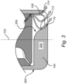
- Fig. 3 conceptually illustrates a comparative example not covered by the claims. This embodiment may be primarily intended for a single-hole cap with a main hole-direction presenting a certain angle related to the injector centre axis direction.
- the nozzle cap 300 illustrated in fig. 3 differs from that shown in fig. 2A-B in that the internal bottom flow-guiding body 309 is shaped to substantially fill the side 140 of the nozzle cap opposite the outlet 108. In other words, instead of leaving an open volume on the side of the internal bottom flow-guiding body 109 where there is no outlet, the internal bottom flow-guiding body 309 fills up that volume. This significantly reduces the amount of residual hydrogen that can remain in the nozzle cap 300.
- the first internal side flow-guiding body 518 is shaped with a convex outer surface to allow for receiving the flow form the inlet and guide the flow over surface of the guiding the flow along the internal flow-guiding body 518, with assistance from the oppositely arranged internal bottom flow-guiding body 509 with respect to the outlets 508a-b.
- the internal bottom flow-guiding body comprising a set of flow-guiding surfaces for re-directing a flow of hydrogen towards each of the outlets.
- the internal bottom flow-guiding body is advantageous to have the internal bottom flow-guiding body to be shaped to fill-out the volume between two outlets in the nozzle cap volume.
- the internal bottom flow-guiding body reaches across the entire inner volume of the nozzle cap, from side-to-side, but leaves the openings open.
- the internal bottom flow-guiding body 509, 109 is centralized in the bottom of the nozzle cap.
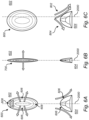
- Figs. 6A-F conceptually illustrates different configurations for internal bottom flow-guiding bodies.
- example height curves and shapes of the internal bottom flow-guiding bodies are illustrated.
- the shape of the internal bottom flow-guiding bodies is generally configured to assist the flow of hydrogen to efficiently reach the outlet of the nozzle cap in a preferred direction.
- Fig. 6A is a top view 602 and a side view 604 of an internal bottom flow-guiding body 600 according to the claims and having a convex outer shape.
- the flow-guiding surfaces 606 have a convex shape and are configured to direct flow of hydrogen from the inlet to the outlet as described herein.
- the flow-guiding surfaces 606 have a relatively shallow slope. Further, at side portions 608 a passage is formed between the internal bottom flow-guiding body 600 and the inlet valve pintle (not shown in fig. 6A ).
- the axis 2000 indicates the centre of the nozzle cap, thus, the internal bottom flow-guiding body 600 is here indicated as centralized in the nozzle cap.
- Fig. 6B is a top view 602 and a side view 604 of an internal bottom flow-guiding body 700 according to the claims and having a convex outer shape but with a narrower side-ways extension compare to the internal bottom flow-guiding body 600 shown in fig. 6A .
- the internal bottom flow-guiding body 700 is configured as barrier type structures that allows minimal cross-flow between the sides of the internal bottom flow-guiding body 700.
- Fig. 6E is a top view 602 and a side view 604 of an internal bottom flow-guiding body 1000 not covered by the claims, adapted to fill out one side of the nozzle cap opposite the outlet.
- a flow-guiding surface 1006 adapted to guide a flow of hydrogen towards an outlet.
- the other side of the internal bottom flow-guiding body 1000 fills out the volume of the nozzle cap on that side. Thus, very little flow is directed towards the fill out side of the nozzle cap.
- Fig. 6F is a top view 602 and a side view 604 of an internal bottom flow-guiding body 1100 not covered by the claims, having a concave outer shape.
- the flow-guiding surfaces 1106 having a concave shape are advantageous for directing the flow of hydrogen towards the centre of the outlets 108, in other words, the concave shape of the flow-guiding surfaces 1106 provides for converging the flow towards the centre of the outlets 108.
- Fig. 7 conceptually illustrates a perspective cross-section of a nozzle cap 1300 according to embodiments of the invention.
- the internal bottom flow-guiding body 1309 comprises a flow-guiding element 1312 protruding from the upper ridge 1314 of the internal bottom flow-guiding body 1309. This provides for adjusting of the hydrogen-flow in the nozzle cap towards preferred directions.
- the flow-guiding element 1312 is specifically adapted to guide the minor flow going from the valve-seat in the region between the nozzle cap outlets 108a,b such that the flow in this location between the outlets is better directed towards the outlets 108a,b.
- the flow-guiding element 1312 is thus designed to redirect downwards going flow reaching the bottom flow-guiding body 1309 at locations between the outlets 108a, 108b.
- the nozzle caps are preferably made of steel.
Landscapes
- Engineering & Computer Science (AREA)
- Chemical & Material Sciences (AREA)
- Combustion & Propulsion (AREA)
- Mechanical Engineering (AREA)
- General Engineering & Computer Science (AREA)
- Chemical Kinetics & Catalysis (AREA)
- General Chemical & Material Sciences (AREA)
- Oil, Petroleum & Natural Gas (AREA)
- Nozzles (AREA)
- Fuel Cell (AREA)
Claims (15)
- Düsenkappe (100) für eine Kraftstoffeinspritzdüse zum Betrieb in einem Wasserstoffverbrennungsmotor (2), die Düsenkappe umfassend:einen Einlass (104) zur Aufnahme eines Wasserstoffstroms, der durch ein Einlassventil (106) gesteuert werden kann, das in dem Einlass angeordnet werden kann,mindestens einen Auslass (108) zur Bereitstellung eines Austrittsstroms von Wasserstoff undeinen inneren Bodenströmungsleitkörper (109), der an einer Unterseite (110) der Düsenkappe nach dem Einlasses in einem Düsenkappenvolumen (111) angeordnet ist, wobei der innere Bodenströmungsleitkörper eine konvexe Rippe umfasst, die in Richtung des Einlasses vorsteht, und eine Strömungsleitfläche (112) zum Umleiten eines Wasserstoffstroms vom Einlass zum Auslass umfasst,dadurch gekennzeichnet, dassdie konvexe Rippe im Boden der Düsenkappe zentralisiert ist und so angeordnet ist, dass sie von Seite zu Seite über das gesamte Düsenkappenvolumen (111) reicht.
- Düsenkappe nach Anspruch 1, wobei der Auslass eine erste Austrittsfläche (114) und eine zweite Austrittsfläche (116) umfasst, die den Auslass bilden, wobei die Form der ersten Austrittsfläche im Wesentlichen der Form der zweiten Austrittsfläche folgt, so dass der Austrittsstrom von Wasserstoff aus dem Auslass an der ersten Austrittsfläche im Wesentlichen die gleiche Richtung hat wie der Austrittsstrom von Wasserstoff an der zweiten Austrittsfläche.
- Düsenkappe nach einem der Ansprüche 1 und 2, ferner umfassend mindestens einen ersten Innenseite-Strömungsleitkörper (518), der an einer Seitenwandfläche der Düsenkappe angeordnet ist und in einem Düsenkappenvolumen nach innen ragt, um den Wasserstoffstrom zu dem mindestens einen Auslass zu leiten.
- Düsenkappe nach Anspruch 3, wobei der Auslass eine erste Austrittsfläche und eine zweite Austrittsfläche umfasst, die den Auslass bilden, wobei die Form des mindestens einen ersten Innenseite-Strömungsleitkörper im Wesentlichen einer Form der Strömungsleitfläche des inneren Bodenströmungsleitkörpers folgt, so dass der Austrittsstrom von Wasserstoff aus dem Auslass an der ersten Austrittsfläche im Wesentlichen die gleiche Richtung hat wie der Austrittsstrom von Wasserstoff an der zweiten Austrittsfläche.
- Düsenkappe nach Anspruch 1, wobei der Auslass eine erste Austrittsfläche und eine zweite Austrittsfläche umfasst, die den Auslass bilden, wobei die erste Austrittsfläche und eine zweite Austrittsfläche zusammen einen konischen Auslass bilden.
- Düsenkappe nach einem der vorhergehenden Ansprüche, wobei der Auslass eine erste Austrittsfläche und eine zweite Austrittsfläche umfasst, wobei die Strömungsleitfläche des inneren Bodenströmungsleitkörpers neben der zweiten Austrittsfläche angeordnet ist, wobei die Strömungsleitfläche und die zweite Austrittsfläche so konfiguriert sind, dass sie zusammenwirkend den Austrittsstrom von Wasserstoff an der zweiten Austrittsfläche in die gleiche Richtung lenken wie den Austrittsstrom von Wasserstoff an der ersten Austrittsfläche.
- Düsenkappe nach einem der vorhergehenden Ansprüche, wobei der innere Bodenströmungsleitkörper im Boden der Düsenkappe zentriert ist.
- Düsenkappe nach einem der Ansprüche 1 bis 6, wobei der innere Bodenströmungsleitkörper von der Mitte des Bodens der Düsenkappe abgesetzt angeordnet ist.
- Düsenkappe nach einem der vorhergehenden Ansprüche 1 bis 6, wobei der innere Bodenströmungsleitkörper so geformt ist, dass er im Wesentlichen die dem Auslass gegenüberliegende Seite (140) der Düsenkappe ausfüllt.
- Düsenkappe nach einem der vorhergehenden Ansprüche, wobei der innere Bodenströmungsleitkörper eine konvexe Außenform aufweist.
- Düsenkappe nach einem der Ansprüche 1 bis 9, wobei der innere Bodenströmungsleitkörper eine konkave Außenform aufweist.
- Düsenkappe nach einem der vorhergehenden Ansprüche, wobei der innere Bodenströmungsleitkörper Strömungsleitelemente (1312) umfasst, die von der oberen Rippe (1314) des inneren Bodenströmungsleitkörpers vorstehen, um weitere Einstellungen des Wasserstoffstroms in der Düsenkappe zu ermöglichen.
- Kraftstoffeinspritzdüse umfassend ein Einlassventil und eine Düsenkappe nach einem der vorhergehenden Ansprüche.
- Wasserstoffverbrennungsmotor (2) umfassend eine Kraftstoffeinspritzdüse nach Anspruch 13.
- Fahrzeug (1) umfassend eine Kraftstoffeinspritzdüse nach Anspruch 13 oder ein Wasserstoffverbrennungsmotor nach Anspruch 14.
Applications Claiming Priority (1)
| Application Number | Priority Date | Filing Date | Title |
|---|---|---|---|
| PCT/EP2021/070707 WO2023001384A1 (en) | 2021-07-23 | 2021-07-23 | A nozzle cap for a fuel injection nozzle operable in a hydrogen internal combustion engine |
Publications (3)
| Publication Number | Publication Date |
|---|---|
| EP4374058A1 EP4374058A1 (de) | 2024-05-29 |
| EP4374058B1 true EP4374058B1 (de) | 2025-07-09 |
| EP4374058C0 EP4374058C0 (de) | 2025-07-09 |
Family
ID=77168241
Family Applications (1)
| Application Number | Title | Priority Date | Filing Date |
|---|---|---|---|
| EP21749162.0A Active EP4374058B1 (de) | 2021-07-23 | 2021-07-23 | Düsenkappe für eine kraftstoffeinspritzdüse zum betrieb in einem wasserstoffverbrennungsmotor |
Country Status (4)
| Country | Link |
|---|---|
| US (1) | US12146455B2 (de) |
| EP (1) | EP4374058B1 (de) |
| CN (1) | CN117545915A (de) |
| WO (1) | WO2023001384A1 (de) |
Families Citing this family (8)
| Publication number | Priority date | Publication date | Assignee | Title |
|---|---|---|---|---|
| DE102023206011A1 (de) | 2023-06-26 | 2025-01-02 | Robert Bosch Gesellschaft mit beschränkter Haftung | Injektor zum Einblasen eines gasförmigen Mediums |
| DE102023213160A1 (de) | 2023-12-21 | 2025-06-26 | Robert Bosch Gesellschaft mit beschränkter Haftung | Einblasanlage mit einem Injektor zum Einblasen eines gasförmigen Mediums |
| DE102023213164A1 (de) | 2023-12-21 | 2025-06-26 | Robert Bosch Gesellschaft mit beschränkter Haftung | Injektor zum Einblasen eines gasförmigen Mediums |
| DE102024206547A1 (de) | 2024-07-11 | 2026-01-15 | Robert Bosch Gesellschaft mit beschränkter Haftung | Injektor zum Einblasen eines gasförmigen Mediums |
| DE102024208934A1 (de) | 2024-09-18 | 2026-03-19 | Robert Bosch Gesellschaft mit beschränkter Haftung | Injektoranordnung zum Einblasen eines gasförmigen Mediums |
| WO2026077566A1 (de) | 2024-10-10 | 2026-04-16 | Robert Bosch Gmbh | Injektor zum einblasen eines gasförmigen mediums |
| WO2026077680A1 (de) | 2024-10-10 | 2026-04-16 | Robert Bosch Gmbh | Injektor zum einblasen eines gasförmigen mediums |
| DE102024210666A1 (de) | 2024-11-06 | 2026-05-07 | Robert Bosch Gesellschaft mit beschränkter Haftung | Injektor zum Einblasen eines gasförmigen Mediums |
Family Cites Families (33)
| Publication number | Priority date | Publication date | Assignee | Title |
|---|---|---|---|---|
| US1700903A (en) * | 1929-02-05 | Gasifier device and method of installation in internal-combustion | ||
| FR456230A (fr) * | 1912-06-12 | 1913-08-20 | Schneider & Cie | Buse d'introduction de combustible pour moteurs à explosions |
| DE3123398C2 (de) * | 1981-06-12 | 1985-04-25 | MTU Motoren- und Turbinen-Union München GmbH, 8000 München | Vorbrennkammer für Dieselmaschinen |
| US4483291A (en) * | 1982-04-07 | 1984-11-20 | Artman Noel G | Process of segregating air-fuel mass in engine auxiliary chamber |
| US4862857A (en) * | 1988-02-12 | 1989-09-05 | Outboard Marine Corporation | Fuel injection system for multi cylinder two-stroke engine |
| US5035360A (en) * | 1990-07-02 | 1991-07-30 | The University Of Toronto Innovations Foundation | Electrically actuated gaseous fuel timing and metering device |
| JP2778292B2 (ja) * | 1991-06-06 | 1998-07-23 | トヨタ自動車株式会社 | 内燃機関の燃料噴射装置 |
| US5222993A (en) * | 1992-09-28 | 1993-06-29 | Gas Research Institute | Ignition system for water-cooled gas engines |
| DE4312756A1 (de) * | 1993-04-20 | 1994-10-27 | Bosch Gmbh Robert | Vorrichtung zur Einspritzung eines Brennstoff-Gas-Gemisches |
| FR2713280B1 (fr) * | 1993-12-01 | 1996-02-23 | Peugeot | Moteur à allumage par compression à écoulement de gaz dirigé, à la sortie d'une chambre de turbulence. |
| US5484108A (en) * | 1994-03-31 | 1996-01-16 | Siemens Automotive L.P. | Fuel injector having novel multiple orifice disk members |
| DE19505886A1 (de) * | 1995-02-21 | 1996-08-22 | Bosch Gmbh Robert | Vorrichtung zur Einspritzung eines Brennstoff-Gas-Gemisches |
| US5924402A (en) * | 1997-02-24 | 1999-07-20 | Chrysler Corporation | Pre-combustion chamber for an internal combustion engine |
| US6854439B2 (en) * | 2002-03-02 | 2005-02-15 | Jose Francisco Regueiro | Prechamber combustion system |
| JP2006144774A (ja) * | 2004-10-18 | 2006-06-08 | Denso Corp | 気体燃料噴射インジェクタ |
| US7168637B2 (en) * | 2004-11-05 | 2007-01-30 | Visteon Global Technologies, Inc. | Low pressure fuel injector nozzle |
| US7051957B1 (en) * | 2004-11-05 | 2006-05-30 | Visteon Global Technologies, Inc. | Low pressure fuel injector nozzle |
| US7198207B2 (en) * | 2004-11-05 | 2007-04-03 | Visteon Global Technologies, Inc. | Low pressure fuel injector nozzle |
| US7487750B2 (en) | 2005-11-29 | 2009-02-10 | Ford Global Technologies, Llc | Variable intake valve and exhaust valve timing strategy for improving performance in a hydrogen fueled engine |
| DE102006039973A1 (de) * | 2006-08-25 | 2008-02-28 | Bayerische Motoren Werke Ag | Einrichtung und Verfahren zur Bereitstellung eines Kraftstoff-Luft-Gemisches für eine Brennkraftmaschine |
| US20150211458A1 (en) * | 2012-08-01 | 2015-07-30 | 3M Innovative Properties Company | Targeting of fuel output by off-axis directing of nozzle output streams |
| JP5811979B2 (ja) * | 2012-09-24 | 2015-11-11 | 株式会社デンソー | 燃料噴射弁 |
| KR101583931B1 (ko) * | 2014-05-16 | 2016-01-21 | 현대자동차주식회사 | 연료전지 시스템의 이젝터 |
| DK3015679T3 (en) * | 2014-10-31 | 2019-03-11 | Winterthur Gas & Diesel Ag | Cylinder for a piston combustion engine, piston combustion engine and method for operating a piston combustion engine |
| DE102014224344A1 (de) * | 2014-11-28 | 2016-06-02 | Robert Bosch Gmbh | Gasinjektor mit nach außen öffnendem Ventilschließelement |
| DE102014224339A1 (de) * | 2014-11-28 | 2016-06-02 | Robert Bosch Gmbh | Direkteinblasender Gasinjektor mit verbesserter Kühlung |
| CN104863760B (zh) | 2015-06-08 | 2017-06-30 | 北京工业大学 | 一种掺氢实现内燃机全节气门运行的装置及方法 |
| US10502425B2 (en) * | 2016-06-03 | 2019-12-10 | General Electric Company | Contoured shroud swirling pre-mix fuel injector assembly |
| FR3061743B1 (fr) * | 2017-01-12 | 2019-08-16 | Vianney Rabhi | Prechambre d'allumage a clapet |
| US10487787B2 (en) * | 2017-06-20 | 2019-11-26 | Caterpillar Inc. | Injector tip for a fuel injector |
| CN107143421A (zh) | 2017-06-27 | 2017-09-08 | 北京工业大学 | 一种电控缸内直喷二冲程氢内燃机及控制方法 |
| WO2019206899A1 (en) * | 2018-04-25 | 2019-10-31 | Robert Bosch Gmbh | Fuel injector valve seat assembly including an insert formed in place and a method of manufacturing same |
| CN112211714A (zh) * | 2020-11-27 | 2021-01-12 | 山东交通学院 | 一种气体发动机激波助燃预燃室结构 |
-
2021
- 2021-07-23 CN CN202180099634.5A patent/CN117545915A/zh active Pending
- 2021-07-23 WO PCT/EP2021/070707 patent/WO2023001384A1/en not_active Ceased
- 2021-07-23 US US18/579,724 patent/US12146455B2/en active Active
- 2021-07-23 EP EP21749162.0A patent/EP4374058B1/de active Active
Also Published As
| Publication number | Publication date |
|---|---|
| EP4374058A1 (de) | 2024-05-29 |
| US12146455B2 (en) | 2024-11-19 |
| EP4374058C0 (de) | 2025-07-09 |
| US20240344488A1 (en) | 2024-10-17 |
| CN117545915A (zh) | 2024-02-09 |
| WO2023001384A1 (en) | 2023-01-26 |
Similar Documents
| Publication | Publication Date | Title |
|---|---|---|
| EP4374058B1 (de) | Düsenkappe für eine kraftstoffeinspritzdüse zum betrieb in einem wasserstoffverbrennungsmotor | |
| USRE40886E1 (en) | Fuel injection valve for an internal combustion engine | |
| US10208711B2 (en) | Gas injector including an outwardly opening valve closure element | |
| JP5536953B2 (ja) | 噴射ノズル | |
| US10982639B2 (en) | Fuel injector | |
| KR100312085B1 (ko) | 내연기관용연료분사밸브 | |
| US20150021414A1 (en) | Fuel Injector | |
| EP0370659B1 (de) | Kraftstoffeinspritzdüse | |
| US4650121A (en) | Injection nozzle for an air-compression fuel-injection internal combustion engine | |
| WO2024200096A1 (en) | Gas injector for hydrogen ice | |
| EP1795744A1 (de) | Kraftstoffeinspritzvorrichtung | |
| US4986478A (en) | Injection valve | |
| JP4123513B2 (ja) | 燃料噴射弁 | |
| US5785257A (en) | Swirl type fuel injection valve | |
| JP2008255908A (ja) | 噴孔プレートおよびそれを備えた燃料噴射弁 | |
| EP1771654A1 (de) | Asymmetrische stanze | |
| US20040188550A1 (en) | Fuel injection valve | |
| JP2002524685A (ja) | 内燃機関のための燃料噴射弁 | |
| JPH1113598A (ja) | 燃料噴射ノズル | |
| KR102958393B1 (ko) | 유량 제어용 고압 유량조절밸브 | |
| JPH0583369U (ja) | 燃料噴射ノズル | |
| CN114402134B (zh) | 燃料喷射器 | |
| JP4561621B2 (ja) | 内燃機関の吸気装置 | |
| WO2002059476A3 (de) | Brennstoffeinspritzventil | |
| GB2207463A (en) | I.C. engine petrol injector |
Legal Events
| Date | Code | Title | Description |
|---|---|---|---|
| STAA | Information on the status of an ep patent application or granted ep patent |
Free format text: STATUS: UNKNOWN |
|
| STAA | Information on the status of an ep patent application or granted ep patent |
Free format text: STATUS: THE INTERNATIONAL PUBLICATION HAS BEEN MADE |
|
| PUAI | Public reference made under article 153(3) epc to a published international application that has entered the european phase |
Free format text: ORIGINAL CODE: 0009012 |
|
| STAA | Information on the status of an ep patent application or granted ep patent |
Free format text: STATUS: REQUEST FOR EXAMINATION WAS MADE |
|
| 17P | Request for examination filed |
Effective date: 20240116 |
|
| AK | Designated contracting states |
Kind code of ref document: A1 Designated state(s): AL AT BE BG CH CY CZ DE DK EE ES FI FR GB GR HR HU IE IS IT LI LT LU LV MC MK MT NL NO PL PT RO RS SE SI SK SM TR |
|
| DAV | Request for validation of the european patent (deleted) | ||
| DAX | Request for extension of the european patent (deleted) | ||
| GRAP | Despatch of communication of intention to grant a patent |
Free format text: ORIGINAL CODE: EPIDOSNIGR1 |
|
| STAA | Information on the status of an ep patent application or granted ep patent |
Free format text: STATUS: GRANT OF PATENT IS INTENDED |
|
| INTG | Intention to grant announced |
Effective date: 20250226 |
|
| GRAS | Grant fee paid |
Free format text: ORIGINAL CODE: EPIDOSNIGR3 |
|
| GRAA | (expected) grant |
Free format text: ORIGINAL CODE: 0009210 |
|
| STAA | Information on the status of an ep patent application or granted ep patent |
Free format text: STATUS: THE PATENT HAS BEEN GRANTED |
|
| AK | Designated contracting states |
Kind code of ref document: B1 Designated state(s): AL AT BE BG CH CY CZ DE DK EE ES FI FR GB GR HR HU IE IS IT LI LT LU LV MC MK MT NL NO PL PT RO RS SE SI SK SM TR |
|
| REG | Reference to a national code |
Ref country code: GB Ref legal event code: FG4D |
|
| REG | Reference to a national code |
Ref country code: CH Ref legal event code: EP |
|
| REG | Reference to a national code |
Ref country code: IE Ref legal event code: FG4D |
|
| REG | Reference to a national code |
Ref country code: DE Ref legal event code: R096 Ref document number: 602021033811 Country of ref document: DE |
|
| U01 | Request for unitary effect filed |
Effective date: 20250716 |
|
| U07 | Unitary effect registered |
Designated state(s): AT BE BG DE DK EE FI FR IT LT LU LV MT NL PT RO SE SI Effective date: 20250723 |
|
| U20 | Renewal fee for the european patent with unitary effect paid |
Year of fee payment: 5 Effective date: 20250724 |
|
| PG25 | Lapsed in a contracting state [announced via postgrant information from national office to epo] |
Ref country code: IS Free format text: LAPSE BECAUSE OF FAILURE TO SUBMIT A TRANSLATION OF THE DESCRIPTION OR TO PAY THE FEE WITHIN THE PRESCRIBED TIME-LIMIT Effective date: 20251109 |
|
| PG25 | Lapsed in a contracting state [announced via postgrant information from national office to epo] |
Ref country code: NO Free format text: LAPSE BECAUSE OF FAILURE TO SUBMIT A TRANSLATION OF THE DESCRIPTION OR TO PAY THE FEE WITHIN THE PRESCRIBED TIME-LIMIT Effective date: 20251009 |
|
| PG25 | Lapsed in a contracting state [announced via postgrant information from national office to epo] |
Ref country code: HR Free format text: LAPSE BECAUSE OF FAILURE TO SUBMIT A TRANSLATION OF THE DESCRIPTION OR TO PAY THE FEE WITHIN THE PRESCRIBED TIME-LIMIT Effective date: 20250709 |
|
| PG25 | Lapsed in a contracting state [announced via postgrant information from national office to epo] |
Ref country code: GR Free format text: LAPSE BECAUSE OF FAILURE TO SUBMIT A TRANSLATION OF THE DESCRIPTION OR TO PAY THE FEE WITHIN THE PRESCRIBED TIME-LIMIT Effective date: 20251010 |
|
| PG25 | Lapsed in a contracting state [announced via postgrant information from national office to epo] |
Ref country code: PL Free format text: LAPSE BECAUSE OF FAILURE TO SUBMIT A TRANSLATION OF THE DESCRIPTION OR TO PAY THE FEE WITHIN THE PRESCRIBED TIME-LIMIT Effective date: 20250709 |
|
| PG25 | Lapsed in a contracting state [announced via postgrant information from national office to epo] |
Ref country code: RS Free format text: LAPSE BECAUSE OF FAILURE TO SUBMIT A TRANSLATION OF THE DESCRIPTION OR TO PAY THE FEE WITHIN THE PRESCRIBED TIME-LIMIT Effective date: 20251009 |
|
| PG25 | Lapsed in a contracting state [announced via postgrant information from national office to epo] |
Ref country code: ES Free format text: LAPSE BECAUSE OF FAILURE TO SUBMIT A TRANSLATION OF THE DESCRIPTION OR TO PAY THE FEE WITHIN THE PRESCRIBED TIME-LIMIT Effective date: 20250709 |
|
| REG | Reference to a national code |
Ref country code: CH Ref legal event code: H13 Free format text: ST27 STATUS EVENT CODE: U-0-0-H10-H13 (AS PROVIDED BY THE NATIONAL OFFICE) Effective date: 20260224 |
|
| PG25 | Lapsed in a contracting state [announced via postgrant information from national office to epo] |
Ref country code: SM Free format text: LAPSE BECAUSE OF FAILURE TO SUBMIT A TRANSLATION OF THE DESCRIPTION OR TO PAY THE FEE WITHIN THE PRESCRIBED TIME-LIMIT Effective date: 20250709 |
|
| PG25 | Lapsed in a contracting state [announced via postgrant information from national office to epo] |
Ref country code: CZ Free format text: LAPSE BECAUSE OF FAILURE TO SUBMIT A TRANSLATION OF THE DESCRIPTION OR TO PAY THE FEE WITHIN THE PRESCRIBED TIME-LIMIT Effective date: 20250709 Ref country code: CH Free format text: LAPSE BECAUSE OF NON-PAYMENT OF DUE FEES Effective date: 20250731 |
|
| PG25 | Lapsed in a contracting state [announced via postgrant information from national office to epo] |
Ref country code: SK Free format text: LAPSE BECAUSE OF FAILURE TO SUBMIT A TRANSLATION OF THE DESCRIPTION OR TO PAY THE FEE WITHIN THE PRESCRIBED TIME-LIMIT Effective date: 20250709 |