EP4370885B1 - Temperaturmesseinrichtung, dachbedienvorrichtung sowie system zum bereitstellen eines temperaturwerts für eine klimaanlage eines kraftfahrzeugs - Google Patents
Temperaturmesseinrichtung, dachbedienvorrichtung sowie system zum bereitstellen eines temperaturwerts für eine klimaanlage eines kraftfahrzeugs Download PDFInfo
- Publication number
- EP4370885B1 EP4370885B1 EP22738499.7A EP22738499A EP4370885B1 EP 4370885 B1 EP4370885 B1 EP 4370885B1 EP 22738499 A EP22738499 A EP 22738499A EP 4370885 B1 EP4370885 B1 EP 4370885B1
- Authority
- EP
- European Patent Office
- Prior art keywords
- circuit board
- temperature
- roof
- printed circuit
- measuring device
- Prior art date
- Legal status (The legal status is an assumption and is not a legal conclusion. Google has not performed a legal analysis and makes no representation as to the accuracy of the status listed.)
- Active
Links
Images



Classifications
-
- B—PERFORMING OPERATIONS; TRANSPORTING
- B60—VEHICLES IN GENERAL
- B60H—ARRANGEMENTS OF HEATING, COOLING, VENTILATING OR OTHER AIR-TREATING DEVICES SPECIALLY ADAPTED FOR PASSENGER OR GOODS SPACES OF VEHICLES
- B60H1/00—Heating, cooling or ventilating devices
- B60H1/00642—Control systems or circuits; Control members or indication devices for heating, cooling or ventilating devices
- B60H1/00735—Control systems or circuits characterised by their input, i.e. by the detection, measurement or calculation of particular conditions, e.g. signal treatment, dynamic models
- B60H1/00792—Arrangement of detectors
-
- B—PERFORMING OPERATIONS; TRANSPORTING
- B60—VEHICLES IN GENERAL
- B60K—ARRANGEMENT OR MOUNTING OF PROPULSION UNITS OR OF TRANSMISSIONS IN VEHICLES; ARRANGEMENT OR MOUNTING OF PLURAL DIVERSE PRIME-MOVERS IN VEHICLES; AUXILIARY DRIVES FOR VEHICLES; INSTRUMENTATION OR DASHBOARDS FOR VEHICLES; ARRANGEMENTS IN CONNECTION WITH COOLING, AIR INTAKE, GAS EXHAUST OR FUEL SUPPLY OF PROPULSION UNITS IN VEHICLES
- B60K35/00—Instruments specially adapted for vehicles; Arrangement of instruments in or on vehicles
- B60K35/20—Output arrangements, i.e. from vehicle to user, associated with vehicle functions or specially adapted therefor
- B60K35/28—Output arrangements, i.e. from vehicle to user, associated with vehicle functions or specially adapted therefor characterised by the type of the output information, e.g. video entertainment or vehicle dynamics information; characterised by the purpose of the output information, e.g. for attracting the attention of the driver
-
- B—PERFORMING OPERATIONS; TRANSPORTING
- B60—VEHICLES IN GENERAL
- B60K—ARRANGEMENT OR MOUNTING OF PROPULSION UNITS OR OF TRANSMISSIONS IN VEHICLES; ARRANGEMENT OR MOUNTING OF PLURAL DIVERSE PRIME-MOVERS IN VEHICLES; AUXILIARY DRIVES FOR VEHICLES; INSTRUMENTATION OR DASHBOARDS FOR VEHICLES; ARRANGEMENTS IN CONNECTION WITH COOLING, AIR INTAKE, GAS EXHAUST OR FUEL SUPPLY OF PROPULSION UNITS IN VEHICLES
- B60K35/00—Instruments specially adapted for vehicles; Arrangement of instruments in or on vehicles
- B60K35/10—Input arrangements, i.e. from user to vehicle, associated with vehicle functions or specially adapted therefor
-
- B—PERFORMING OPERATIONS; TRANSPORTING
- B60—VEHICLES IN GENERAL
- B60K—ARRANGEMENT OR MOUNTING OF PROPULSION UNITS OR OF TRANSMISSIONS IN VEHICLES; ARRANGEMENT OR MOUNTING OF PLURAL DIVERSE PRIME-MOVERS IN VEHICLES; AUXILIARY DRIVES FOR VEHICLES; INSTRUMENTATION OR DASHBOARDS FOR VEHICLES; ARRANGEMENTS IN CONNECTION WITH COOLING, AIR INTAKE, GAS EXHAUST OR FUEL SUPPLY OF PROPULSION UNITS IN VEHICLES
- B60K35/00—Instruments specially adapted for vehicles; Arrangement of instruments in or on vehicles
- B60K35/20—Output arrangements, i.e. from vehicle to user, associated with vehicle functions or specially adapted therefor
- B60K35/21—Output arrangements, i.e. from vehicle to user, associated with vehicle functions or specially adapted therefor using visual output, e.g. blinking lights or matrix displays
- B60K35/22—Display screens
-
- B—PERFORMING OPERATIONS; TRANSPORTING
- B60—VEHICLES IN GENERAL
- B60K—ARRANGEMENT OR MOUNTING OF PROPULSION UNITS OR OF TRANSMISSIONS IN VEHICLES; ARRANGEMENT OR MOUNTING OF PLURAL DIVERSE PRIME-MOVERS IN VEHICLES; AUXILIARY DRIVES FOR VEHICLES; INSTRUMENTATION OR DASHBOARDS FOR VEHICLES; ARRANGEMENTS IN CONNECTION WITH COOLING, AIR INTAKE, GAS EXHAUST OR FUEL SUPPLY OF PROPULSION UNITS IN VEHICLES
- B60K35/00—Instruments specially adapted for vehicles; Arrangement of instruments in or on vehicles
- B60K35/60—Instruments characterised by their location or relative disposition in or on vehicles
-
- G—PHYSICS
- G01—MEASURING; TESTING
- G01K—MEASURING TEMPERATURE; MEASURING QUANTITY OF HEAT; THERMALLY-SENSITIVE ELEMENTS NOT OTHERWISE PROVIDED FOR
- G01K1/00—Details of thermometers not specially adapted for particular types of thermometer
- G01K1/16—Special arrangements for conducting heat from the object to the sensitive element
-
- G—PHYSICS
- G01—MEASURING; TESTING
- G01K—MEASURING TEMPERATURE; MEASURING QUANTITY OF HEAT; THERMALLY-SENSITIVE ELEMENTS NOT OTHERWISE PROVIDED FOR
- G01K1/00—Details of thermometers not specially adapted for particular types of thermometer
- G01K1/20—Compensating for effects of temperature changes other than those to be measured, e.g. changes in ambient temperature
-
- B—PERFORMING OPERATIONS; TRANSPORTING
- B60—VEHICLES IN GENERAL
- B60K—ARRANGEMENT OR MOUNTING OF PROPULSION UNITS OR OF TRANSMISSIONS IN VEHICLES; ARRANGEMENT OR MOUNTING OF PLURAL DIVERSE PRIME-MOVERS IN VEHICLES; AUXILIARY DRIVES FOR VEHICLES; INSTRUMENTATION OR DASHBOARDS FOR VEHICLES; ARRANGEMENTS IN CONNECTION WITH COOLING, AIR INTAKE, GAS EXHAUST OR FUEL SUPPLY OF PROPULSION UNITS IN VEHICLES
- B60K2360/00—Indexing scheme associated with groups B60K35/00 or B60K37/00 relating to details of instruments or dashboards
- B60K2360/143—Touch sensitive instrument input devices
-
- B—PERFORMING OPERATIONS; TRANSPORTING
- B60—VEHICLES IN GENERAL
- B60K—ARRANGEMENT OR MOUNTING OF PROPULSION UNITS OR OF TRANSMISSIONS IN VEHICLES; ARRANGEMENT OR MOUNTING OF PLURAL DIVERSE PRIME-MOVERS IN VEHICLES; AUXILIARY DRIVES FOR VEHICLES; INSTRUMENTATION OR DASHBOARDS FOR VEHICLES; ARRANGEMENTS IN CONNECTION WITH COOLING, AIR INTAKE, GAS EXHAUST OR FUEL SUPPLY OF PROPULSION UNITS IN VEHICLES
- B60K2360/00—Indexing scheme associated with groups B60K35/00 or B60K37/00 relating to details of instruments or dashboards
- B60K2360/40—Hardware adaptations for dashboards or instruments
- B60K2360/48—Sensors
-
- B—PERFORMING OPERATIONS; TRANSPORTING
- B60—VEHICLES IN GENERAL
- B60K—ARRANGEMENT OR MOUNTING OF PROPULSION UNITS OR OF TRANSMISSIONS IN VEHICLES; ARRANGEMENT OR MOUNTING OF PLURAL DIVERSE PRIME-MOVERS IN VEHICLES; AUXILIARY DRIVES FOR VEHICLES; INSTRUMENTATION OR DASHBOARDS FOR VEHICLES; ARRANGEMENTS IN CONNECTION WITH COOLING, AIR INTAKE, GAS EXHAUST OR FUEL SUPPLY OF PROPULSION UNITS IN VEHICLES
- B60K2360/00—Indexing scheme associated with groups B60K35/00 or B60K37/00 relating to details of instruments or dashboards
- B60K2360/77—Instrument locations other than the dashboard
- B60K2360/771—Instrument locations other than the dashboard on the ceiling
-
- G—PHYSICS
- G01—MEASURING; TESTING
- G01K—MEASURING TEMPERATURE; MEASURING QUANTITY OF HEAT; THERMALLY-SENSITIVE ELEMENTS NOT OTHERWISE PROVIDED FOR
- G01K2201/00—Application of thermometers in air-conditioning systems
- G01K2201/02—Application of thermometers in air-conditioning systems in vehicles
Definitions
- the invention relates to a temperature measuring device for an air conditioning system of a motor vehicle. Furthermore, the invention relates to a roof control device for a motor vehicle, which comprises such a temperature measuring device. Furthermore, the invention relates to a system for providing a temperature value for an air conditioning system of a motor vehicle, which system comprises such a roof control device and the air conditioning system of the motor vehicle.
- a motor vehicle often has a temperature measuring device for measuring the interior temperature inside the vehicle. Based on a temperature value measured by the temperature measuring device, an air conditioning system in the vehicle can be adjusted and controlled, for example.
- the temperature measuring device in the vehicle typically has a photodiode, which can be used to determine, for example, whether the temperature measuring device is exposed to sunlight. If this is the case and, for example, sunlight hits the temperature sensor or a component of the temperature sensor directly through a window of the vehicle, this can influence the measured temperature value, resulting in, for example, a higher temperature than the actual interior temperature of the vehicle being measured.
- the EP 1 894 757 A1 shows a temperature measuring device for the interior of a motor vehicle, which is positioned on a dashboard of the motor vehicle and exposed to solar radiation through a windshield of the motor vehicle.
- the temperature measuring device has a rigid circuit board with at least two temperature sensors, wherein the circuit board is arranged behind a cap protruding from the dashboard. By evaluating the temperature measurement data provided by the two temperature sensors, the interior temperature of the motor vehicle can ultimately be determined.
- the DE 10 2007 015 231 A1 shows a device for determining a room temperature in a vehicle interior, wherein the device has a thin, flat heat exchange element which is connected via a heat conducting part to a rear Temperature sensor is coupled.
- the device has at least two thermally isolated and non-mutually influencing temperature sensors.
- the US 2018/0058942 A1 shows a temperature detection device for a vehicle interior in which a temperature sensor is arranged on a rigid circuit board.
- state-of-the-art temperature measuring devices are, for example, DE 10 2005 002363 B3 , US 6 997 605 B2 , DE 10 2004 009605 A1 , DE 10 2012 105534 A1 , DE 103 02 285 B4 , and DE 10 2018 132103 A1 known.
- the temperature measuring device has a thermally conductive cap and a circuit board with two temperature sensors.
- the two temperature sensors are arranged spatially spaced from one another on the circuit board.
- the thermally conductive cap is designed such that, in a preferred installation position of the temperature measuring device in the motor vehicle, at least one surface of the thermally conductive cap faces an interior of the motor vehicle.
- the temperature measuring device as a whole is thus designed such that a temperature in the region of the at least one surface of the thermally conductive cap can be measured and provided by means of the temperature measuring device. The temperature can therefore be measured which prevails at a current time in an environment of the cap and which the cap has at the current time.
- the two spatially spaced temperature sensors are arranged at two different positions on the circuit board, with a minimum distance between the two positions.
- the minimum distance is greater than zero and is, for example, one centimeter.
- the minimum distance can be one millimeter, five millimeters, 1.5 centimeters, two centimeters, three centimeters, four centimeters, or five centimeters, whereby it can be any value between one millimeter and five centimeters.
- the two temperature sensors do not touch each other.
- Each of the two temperature sensors preferably continuously measures temperature information that describes a temperature at and/or in a direct environment of the temperature sensor.
- the temperature information includes a value that quantifies the temperature, and/or data that quantifies the temperature. By evaluating the measured temperature information, the temperature of the cap and/or the area surrounding the cap of the temperature measuring device can be determined and provided as a temperature value. In the preferred installation position in the motor vehicle, the determined temperature value corresponds to the interior temperature of the motor vehicle.
- the circuit board of the temperature measuring device is designed as a flexible circuit board.
- the circuit board is therefore, for example, an FPC (flexible printed circuit) film.
- the flexible circuit board is characterized by the fact that electrical lines are printed on a flexible plastic carrier.
- the flexible circuit board is elastically deformable and thus flexible when a force less than a limit force is applied to the circuit board. This means that the flexible circuit board has at least one degree of freedom.
- the two temperature sensors are arranged at a distance from one another on the flexible circuit board, whereby these are preferably designed as respective NTC (negative temperature coefficient) thermistors.
- the individual temperature sensors are therefore preferably designed as so-called thermistors and thus as temperature-dependent resistors.
- at least one of the temperature sensors can be provided as a differently designed temperature sensor.
- the temperature measuring device according to the invention is compact due to the flexible and thus deformable circuit board, while nevertheless enabling reliable temperature measurement by means of the temperature measuring device.
- the temperature measuring device according to the invention does not require a photodiode and can therefore be manufactured particularly cost-effectively, in particular due to the thermally conductive cap in combination with the flexible circuit board.
- the photodiode can be omitted in particular if the preferred installation position for the temperature measuring device is a roof area of the motor vehicle. When installing the temperature measuring device in the motor vehicle, care should therefore be taken to ensure that no sunlight will strike the thermally conductive cap or that there is only a low probability of sunlight striking the thermally conductive cap. In particular, in the preferred installation position, the temperature measuring device can therefore reliably and accurately determine the temperature inside the motor vehicle even without a photodiode.
- the claimed invention provides that a first temperature sensor of the two temperature sensors is designed to provide a first temperature information
- a second temperature sensor of the two temperature sensors is configured to detect a second piece of temperature information.
- the temperature measuring device has an evaluation unit configured to determine a temperature value by applying an evaluation criterion to the detected first and second pieces of temperature information.
- the evaluation unit is preferably also arranged on the flexible printed circuit board. Alternatively or additionally, the evaluation unit can be only indirectly coupled to the flexible printed circuit board.
- the evaluation criterion preferably comprises at least one rule, the application of which to the first and/or second temperature information allows the actual temperature of the environment in the region of the thermally conductive cap to be determined.
- one of the two temperature sensors in particular the second temperature sensor, preferably functions as a comparison sensor for the respective other temperature sensor. Because the two temperature sensors are arranged spatially spaced from one another on the circuit board, the two temperature sensors are not in direct physical contact. Between the two temperature sensors there is a gas, for example air, and/or a liquid and/or a filling material of the temperature measuring device. Because the two temperature sensors are spatially separated from one another, it is ensured that the first and second temperature sensors do not influence one another. The two temperature sensors are approximately thermally insulated from one another.
- the actual temperature of the cap and/or the environment of the cap can be determined accurately and precisely by evaluating the temperature information.
- the temperature value determined in this way can be provided, for example, to the air conditioning system of the motor vehicle in the preferred installation position of the temperature measuring device, so that the air conditioning system can carry out temperature control in the motor vehicle on the basis of the temperature value.
- the claimed invention provides that the circuit board is coupled to the thermally conductive cap in a partial area of the circuit board on a first side of the circuit board.
- the circuit board therefore has a section that is preferably arranged at a first end of the circuit board, wherein the circuit board is only connected at least indirectly to the thermally conductive cap in this section, i.e. in the partial area.
- the circuit board is preferably coupled to the thermally conductive cap on a side of the cap facing away from the interior of the motor vehicle.
- the first temperature sensor is also arranged in the partial area of the
- the circuit board is arranged on the circuit board, but on a second side of the circuit board opposite the first side.
- the circuit board is therefore initially located adjacent to the thermally conductive cap, for example, and the first temperature sensor is only located behind the circuit board when viewed from the thermally conductive cap.
- the first temperature sensor therefore preferably does not directly touch the thermally conductive cap.
- the first temperature sensor is in thermal contact with the thermally conductive cap via the circuit board.
- the first temperature sensor is therefore designed to measure the temperature of the area surrounding the cap assumed by the thermally conductive cap, i.e. an ambient temperature, in the form of the first temperature information. Since the first temperature sensor is also located in the partial area of the circuit board in which the thermally conductive cap is also coupled to the circuit board, the thermally conductive cap and the first temperature sensor are opposite one another and are only separated from one another by at least the circuit board. This enables a particularly compact design of the temperature measuring device.
- the flexible circuit board is coupled to the thermally conductive cap by means of a thermally conductive adhesive.
- the thermally conductive adhesive is located in the partial region on the first side of the circuit board and connects the flexible circuit board to the thermally conductive cap.
- the adhesive is designed, for example, as a thermally conductive double-sided adhesive tape, in particular as an adhesive tape film of this type.
- any adhesive can be selected as long as it is thermally conductive, i.e., the thermally conductive cap is not thermally insulated from the circuit board and the first temperature sensor arranged on the circuit board by the adhesive.
- the thermally conductive cap is made of a plastic.
- the thermally conductive cap is made of polycarbonate.
- any plastic can be used for the cap, provided that the plastic is not thermally insulated, but rather is designed to also assume a temperature prevailing, for example, in the environment of the thermally conductive cap and thus transmit it to the first temperature sensor in such a way that the latter can detect the ambient temperature.
- the choice of a flexible circuit board, the design of the thermally conductive cap as a plastic cap, and the use of, for example, thermally conductive double-sided adhesive tape ensure that the temperature measuring device can be manufactured cost-effectively. It is also compact and flexible in its design, as the use of a flexible circuit board allows for adaptation to any size of room.
- a further aspect of the invention relates to the roof control device according to the invention for a motor vehicle.
- the roof control device has the temperature measuring device described above.
- the temperature measuring device with the thermally conductive cap and the flexible circuit board with the two temperature sensors is thus arranged within the roof control device.
- the temperature value can be determined by means of the temperature measuring device in the roof control device using the evaluation unit of the temperature measuring device.
- the exemplary embodiments described in connection with the temperature measuring device according to the invention and their advantages apply accordingly to the roof control device, which can comprise the temperature measuring device according to one or a combination of the described exemplary embodiments.
- the roof control device has a housing with an opening.
- the thermally conductive cap of the temperature measuring device is arranged in the housing such that a surface of the thermally conductive cap facing away from the flexible circuit board is positioned in the opening.
- the surface of the thermally conductive cap which can alternatively be referred to as the cap surface, is arranged, for example, opposite the side of the thermally conductive cap that is coupled to the thermally conductive circuit board in the partial region of the circuit board on the first side of the circuit board.
- the surface facing away from the flexible circuit board therefore does not face the circuit board and is therefore not arranged opposite it, but faces away from the flexible circuit board and points in a different direction, in particular in the opposite direction.
- the surface of the thermally conductive cap preferably protrudes from the roof control device.
- a plane of the surface of the thermally conductive cap can be aligned parallel to a plane of a surface of the housing around the opening.
- the two planes are identical.
- the planes can be offset from one another.
- the surface of the thermally conductive cap The conductive cap can, for example, either protrude from the opening of the housing into the area surrounding the roof control device or be recessed into the opening, i.e. be arranged in a recess in the housing formed by the opening and protrude relative to the plane of the surface of the housing and thus not protrude from the roof control device above the plane of the surface of the housing in the area of the opening.
- the other components of the temperature measuring device i.e. the flexible circuit board and the two temperature sensors, are located inside the housing and are preferably not visible when looking at the roof control device from the outside, but are hidden by the housing.
- the roof control device is installed in a roof of the motor vehicle.
- it is preferably arranged centrally in a transverse direction of the vehicle in a front region of the motor vehicle, in such a way that it can be easily operated by a user of the motor vehicle from a driver's seat and/or a passenger seat of the motor vehicle with one hand by raising an arm in the direction of the roof of the motor vehicle.
- the opening of the housing faces the vehicle interior. This means that the surface of the thermally conductive cap arranged in the opening faces the vehicle interior and is in contact with the interior of the motor vehicle. The surface of the thermally conductive cap is therefore surrounded by air that typically has an average temperature of the interior of the motor vehicle.
- the thermally conductive cap Due to its arrangement in the roof control device in the roof of the vehicle, the thermally conductive cap is always protected from solar radiation, since sunlight typically cannot penetrate vehicle windows at any time in such a way that it can directly irradiate and thus heat the roof control device, which is arranged centrally in the roof of the vehicle in the transverse direction of the vehicle.
- the arrangement of the temperature measuring device in the roof control device and the roof control device in its preferred installation position thus enables the actual temperature value, which can represent the actual temperature inside the vehicle, to be reliably determined despite the omission of the photodiode.
- the roof control device has a central circuit board.
- the central circuit board is connected to the flexible circuit board of the temperature measuring device by means of a connecting element. At least two circuit boards are therefore located within the roof control device: the central circuit board and the flexible circuit board of the temperature measuring device.
- the central circuit board can, for example, also be designed as a flexible circuit board.
- the flexible circuit board is designed to have evaluation units and/or control units required by the roof control device.
- a processor can, for example, be arranged on the central circuit board, which is designed to control a ceiling light of the motor vehicle that has the roof control device.
- an automatic opening device for a roof window of the motor vehicle can be integrated into the roof control device, wherein the corresponding control unit can also be arranged on the central circuit board.
- the connecting element to the central circuit board is preferably arranged at a second end of the flexible circuit board, wherein the second end represents the end of the flexible circuit board opposite the first end, wherein the partial region coupled to the cap and the first temperature sensor is arranged at the first end.
- the second temperature sensor is arranged between the connecting element and the partial region on the flexible circuit board.
- the connecting element is designed as a zero-force base.
- the zero-force base which can also be referred to as a zero-force socket, is arranged between the central circuit board and the flexible circuit board of the temperature measuring device.
- a component is typically referred to as a PCB ZIF connector, or printed circuit board zero insertion force connector.
- the flexible circuit board can be exchangeably and easily attached to the central circuit board, whereby neither strong compressive nor tensile forces are required for inserting nor removing the two circuit boards from each other.
- this enables the connection between the central circuit board of the roof control device and the flexible circuit board of the temperature measuring device, on which at least the two temperature sensors are arranged, using simple means and at low cost.
- one embodiment provides for the central circuit board to contain the evaluation unit of the temperature measuring device.
- the evaluation unit by means of which the temperature value is ultimately determined, is thus preferably not located as a component on the flexible circuit board of the temperature measuring device itself, but rather is integrated into the central circuit board of the roof control device. This enables a particularly compact and simple design of the flexible circuit board and also allows for the concentration of all evaluation and control units provided in the roof control device on the central circuit board itself.
- the central circuit board is designed as a rigid circuit board.
- the central circuit board is therefore preferably designed as a so-called PCB (printed circuit board).
- PCB printed circuit board
- Such a rigid circuit board can be provided particularly cost-effectively and, with appropriate dimensioning, offers sufficient options for arranging various or all evaluation and control units useful for the roof control device on it.
- the roof control device to have a capacitive or non-capacitive input element.
- the capacitive or non-capacitive input element is connected to the flexible circuit board.
- both a capacitive and a non-capacitive input element can be provided.
- Multiple input elements can be provided.
- the input element can, for example, be arranged adjacent to the thermally conductive cap and thus in the vicinity of the opening in the housing of the roof control device.
- the flexible circuit board can, for example, be designed to be correspondingly extended.
- the input element is arranged at the first end of the flexible circuit board adjacent to the partial region of the flexible circuit board, wherein, viewed from the first end of the flexible circuit board in the direction of the second end of the circuit board, first the input element, then the partial region, and then the connecting element are arranged.
- the capacitive input element is designed, for example, as a capacitive sensor surface, for example as a capacitive touch foil.
- the capacitive input element can be used, for example, to implement a touch-sensitive operating device in the A roof control device may be provided.
- the input element is not directly connected to the rigid central circuit board, but rather connected to it via the flexible circuit board. This allows for a wide variety of relative arrangements of the input element to the thermally conductive cap and thus ultimately within the housing of the roof control device, preferably on a side of the housing facing the interior of the motor vehicle.
- the capacitive or non-capacitive input element can be used, for example, to operate the roof control device.
- a reading light which is also integrated into the housing of the roof control device, can be switched on or off using the input element.
- a surface of the reading light can be designed at least partially or completely as a touch-sensitive film and thus represent a large-area capacitive input element.
- a capacitive or non-capacitive button and/or slider and/or knob can be provided in the roof control device.
- the non-capacitive input element can be designed so that it can be operated mechanically by the user of the motor vehicle.
- a non-capacitive rotary push switch can be provided.
- the roof control device can have the input element and thus be versatile but still internally compact.
- the roof control device has a display device that is connected to the flexible circuit board.
- the display can, for example, be designed to display information and can be connected to the flexible circuit board analogously or alternatively to the capacitive or non-capacitive input element.
- the display device can, for example, be designed as an LED (light-emitting diode) lamp and serve to illuminate the interior of the motor vehicle.
- the individual components of the roof control device can ultimately each be connected to the central circuit board of the roof control device via the flexible circuit board, so that no additional connections are required within the roof control device other than the flexible circuit board.
- Another aspect of the invention relates to a system for providing a temperature value for an air conditioning system of a motor vehicle.
- the system comprises the roof control device described above.
- the system may further comprise a embodiment or a combination of embodiments of the roof control device.
- the system also includes the motor vehicle's air conditioning system.
- the air conditioning system is designed to set and, if necessary, maintain a set temperature independent of weather, waste heat, and/or human and technical emissions in the motor vehicle.
- the air conditioning system can be designed to cool and/or heat the air in the interior of the motor vehicle.
- the roof control device is coupled to the air conditioning system via a vehicle bus.
- the roof control device is designed to transmit a temperature value determined by the evaluation unit of the temperature measuring device of the roof control device to the air conditioning system via the vehicle bus.
- the temperature value determined by the temperature measuring device is thus provided to the motor vehicle's air conditioning system, so that the latter can, for example, adjust the set temperature in the motor vehicle based on this value.
- the advantage of this is that the preferred installation position of the roof control device in the roof of the vehicle ensures that the temperature measuring device is not exposed to direct sunlight. This ultimately allows the temperature of the vehicle's interior to be determined particularly reliably and can be used to control the vehicle's air conditioning system, provided the system is provided in the vehicle.
- the temperature measuring device for the air conditioning system of the motor vehicle comprises a thermally conductive cap, a printed circuit board which is coupled to the thermally conductive cap in a partial region of the printed circuit board on a first side of the printed circuit board, a first temperature sensor which is arranged on the printed circuit board in the partial region on a second side of the printed circuit board opposite the first side and is designed to detect first temperature information, a second temperature sensor which is arranged on the printed circuit board at a spatial distance from the first temperature sensor and the thermally conductive cap and is designed to detect second temperature information, and an evaluation unit which is designed to determine a temperature value by applying an evaluation criterion to the detected first and second temperature information.
- the temperature measuring device is characterized in that the printed circuit board is designed as a flexible printed circuit board.
- Specified concrete values for the minimum distance are to be considered as being included within the scope of the invention, even in the case of deviations, for example due to measurement errors, system errors, DIN tolerances, etc.
- FIG. 1 A motor vehicle 1 is shown, which has an air conditioning system 2 and a roof control device 3.
- the roof control device 3 is controlled by means of a Vehicle bus 6 is connected to the air conditioning system 2 of the motor vehicle 1.
- the roof control device 3 has a temperature measuring device 4.
- FIG. 1 A vehicle longitudinal direction is shown as the x-direction, a vehicle transverse direction as the y-direction, and a vehicle vertical direction as the z-direction.
- the roof control device 3 is preferably arranged centrally in the vehicle transverse direction between two vehicle seats 7 in a front region of the motor vehicle 1.
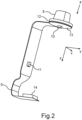
- the temperature measuring device 4 of the roof control device 3 is sketched in a perspective view.
- the temperature measuring device 4 has a thermally conductive cap 8 and a flexible printed circuit board 9 on which two temperature sensors 10, 11 are arranged.
- the thermally conductive cap 8 is made of a plastic, preferably polycarbonate.
- the two temperature sensors 10, 11 are arranged spatially spaced from one another, with a distinction being made here between a first temperature sensor 10 and a second temperature sensor 11.
- the first temperature sensor 10 is designed to detect first temperature information.
- the second temperature sensor 11 is designed to detect second temperature information.
- a thermally conductive adhesive 12 is arranged between the circuit board 9 and the thermally conductive cap 8.
- the thermally conductive adhesive 12 is designed, for example, as a thermally conductive double-sided adhesive tape.
- the circuit board 9 has a partial area 13 of the circuit board 9, in which the circuit board 9 is coupled to the thermally conductive cap 8 by means of the adhesive 12.
- the first temperature sensor 10 is also located on the circuit board 9 in the partial area 13.
- the temperature measuring device 4 has an evaluation unit 14, which is designed to determine a temperature value by applying an evaluation criterion to the detected first and second temperature information.
- the temperature value describes a temperature in a surrounding area of the thermally conductive cap 8.
- the evaluation criterion comprises at least one rule that allows the temperature in the surrounding area of the thermally conductive cap 8 to be deduced from the first and second temperature information.
- the evaluation unit 14 can be connected to a be arranged in any position on the flexible printed circuit board 9.
- the Fig. 2 The position outlined is a possible example for the position of the evaluation unit 14.
- Fig. 3 is a plan view of the roof control device 3.
- the roof control device 3 is arranged in a preferred installation position in a roof 15 of the motor vehicle 1.
- the Fig. 3 The x-, y- and z-directions shown correspond to those for Fig. 1 and Fig. 2 sketched x-, y- and z-directions, i.e. the directions related to the motor vehicle 1. Overall, all coordinate systems shown in the figures always refer to the Fig. 1 outlined directions of the motor vehicle 1.
- the roof control device 3 has a housing 16.
- the housing 16 in turn, has an opening 17.
- the thermally conductive cap 8 of the temperature measuring device 4 is arranged in the housing 16 such that a surface 18 of the thermally conductive cap 8 facing away from the flexible printed circuit board 9 is positioned in the opening 17.
- the roof control device 3 also has a lighting device 19, specifically a reading light for the motor vehicle 1. Furthermore, the roof control device 3 shown here has a capacitive input element 20, a non-capacitive input element 21, and a display device 22.
- the display device 22 can be configured as the lighting device 19 and/or as a screen for displaying display content, for example, for displaying information.
- the capacitive input element 20 can be configured, for example, as a touch-sensitive control element, by means of which, for example, a vehicle roof of the motor vehicle 1 can be controlled and/or the lighting device 19 and/or the display device 22 can be activated or deactivated.
- the non-capacitive input element 21 can, for example, have two push buttons 30, by means of which the vehicle roof can be opened or closed and/or the lighting device 19 and/or the display device 22 can be activated or deactivated.
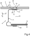
- FIG. 4 A cross-section through the roof control device 3 with the temperature measuring device 4 arranged therein is sketched.
- the housing 16 adjoins an interior of the housing 16, i.e., a housing interior 23, as well as the interior of the motor vehicle 1, i.e., a vehicle interior 24.
- the housing interior 23 is filled with air here.
- a distance between the first temperature sensor 10 and the second temperature sensor 11 can, for example, be approximately one centimeter.
- the surface 18 of the thermally conductive cap 8 is flush with a plane of the housing 16, this plane being formed by a housing surface 29.
- thermally conductive cap 8 can alternatively be offset in the z-direction relative to the housing surface 29 of the housing 16 and, for example, protrude from the opening 17 into the vehicle interior 24 and/or be set back relative to the opening 17 and thus be arranged in a recess of the housing 16 (not shown here). The cap 8 would then be offset in the negative or positive z-direction relative to the housing surface 29.
- the flexible printed circuit board 9 has a first side 25 in the partial area 13 and a second side 26 opposite the first side 25.
- the printed circuit board is coupled to the thermally conductive cap 8 on the first side 25, and the first temperature sensor 10 is arranged on the second side 26.
- the thermally conductive adhesive 12 is located between the thermally conductive cap 8 and the printed circuit board 9 on the first side 25 in the partial area 13.
- the roof control device 3 has a central circuit board 27, which is designed as a rigid circuit board 27.
- a rigid circuit board 27 is understood here to be a PCB (printed circuit board).
- the central circuit board 27 is connected to the flexible circuit board 9 of the temperature measuring device 4 by means of a connecting element 28, which is designed as a zero-force base.
- the central circuit board 27 here has the evaluation unit 14 of the temperature measuring device 4.
- the central circuit board 27 can, for example, have a further evaluation unit, a control unit for an automatic opening device for a roof window of the motor vehicle 1, a control unit for the lighting device 19 and/or a control unit for the capacitive input element 20, the non-capacitive input element 21 and/or the display device 22.
- Fig. 5 shows a perspective view of an embodiment in which the capacitive input element 20, the non-capacitive input element 21 and/or the display device 22 are also connected to the flexible printed circuit board 9.
- the capacitive input element 20 and the non-capacitive input element 21 and also the display device 22 are each connected to the flexible printed circuit board 9.
- the respective input element 20, 21 and/or the display device 22 are connected to the connecting element via the flexible printed circuit board 9. 28 and connected via this to the central circuit board 27 of the roof control device 3.
- the temperature measuring device 4 also has the first temperature sensor 10 as well as the evaluation unit 14 and the connecting element 28, although these are Fig. 4 cannot be seen for perspective reasons.
- the system 5 as a whole is designed to transmit the temperature value determined by the evaluation unit 14 of the temperature measuring device 4 of the roof control device 3 to the air conditioning system 2 of the motor vehicle 1 via the vehicle bus 6, which can be a data bus.
- the air conditioning system 2 can then control air conditioning within the motor vehicle 1 based on the temperature value determined in the roof area, i.e., in the roof 15 of the motor vehicle 1, which represents the temperature in the vehicle interior 24.
- the examples show a temperature measuring device 4 for the air conditioning system 2 of the motor vehicle 1, wherein the temperature measuring device 4 has the thermally conductive cap 8, which can ultimately be mounted in a panel opening of the roof control device 3, i.e., in the opening 17 in the housing 16 in the roof 15 of the motor vehicle 1.
- the cap 8 is mounted on the first side 25 of the flexible printed circuit board 9.
- the first temperature sensor 10 of the temperature measuring device 4 is provided on the opposite second side 26.
- the second temperature sensor 11 is arranged at a distance therefrom on the flexible printed circuit board 9.
- the elastic printed circuit board 9 is part of a capacitive input device, i.e., the capacitive input element 20.
- thermistors surface mount negative temperature coefficient thermistors
- the flexible circuit board 9 also allows for flexible positioning of the two temperature sensors 10, 11 within the temperature measuring device 4 or the roof control device 3.
- additional functions for the roof control device 3 can be integrated particularly easily, such as the capacitive input element 20, the non-capacitive Input element 21 and/or the display device 22.
- a measurement of an interior temperature of the motor vehicle 1 is provided based on an interior temperature of the motor vehicle 1, wherein the surface temperature in the area of the interior of the motor vehicle 1 without direct sunlight, i.e. in the area of the roof 15, is determined.
Landscapes
- Engineering & Computer Science (AREA)
- Mechanical Engineering (AREA)
- Chemical & Material Sciences (AREA)
- Combustion & Propulsion (AREA)
- Transportation (AREA)
- Physics & Mathematics (AREA)
- General Physics & Mathematics (AREA)
- Thermal Sciences (AREA)
- Air-Conditioning For Vehicles (AREA)
- Measuring Temperature Or Quantity Of Heat (AREA)
Description
- Die Erfindung betrifft eine Temperaturmesseinrichtung für eine Klimaanlage eines Kraftfahrzeugs. Des Weiteren betrifft die Erfindung eine Dachbedienvorrichtung für ein Kraftfahrzeug, die eine derartige Temperaturmesseinrichtung aufweist. Ferner betrifft die Erfindung ein System zum Bereitstellen eines Temperaturwerts für eine Klimaanlage eines Kraftfahrzeugs, das eine derartige Dachbedienvorrichtung sowie die Klimaanlage des Kraftfahrzeugs aufweist.
- Ein Kraftfahrzeug weist oft eine Temperaturmesseinrichtung zum Messen einer Innenraumtemperatur im Kraftfahrzeug auf. Basierend auf einem mittels der Temperaturmesseinrichtung gemessenen Temperaturwert kann beispielweise eine Klimaanlage im Kraftfahrzeug eingestellt und gesteuert werden. Die Temperaturmesseinrichtung im Kraftfahrzeug weist typischerweise eine Fotodiode auf, mittels derer beispielweise festgestellt werden kann, ob die Temperaturmesseinrichtung einer Sonneneinstrahlung ausgesetzt ist. Falls dies der Fall ist und beispielweise Sonneneinstrahlung direkt durch eine Scheibe des Kraftfahrzeugs auf den Temperatursensor oder eine Komponente des Temperatursensors trifft, kann dies den gemessenen Temperaturwert beeinflussen, sodass beispielsweise eine höhere Temperatur als die tatsächliche Innenraumtemperatur des Kraftfahrzeugs gemessen wird.
- Die
EP 1 894 757 A1 zeigt eine Temperaturmesseinrichtung für einen Innenraum eines Kraftfahrzeugs, die auf einem Armaturenbrett des Kraftfahrzeugs positioniert und dort einer Sonneneinstrahlung durch eine Windschutzscheibe des Kraftfahrzeugs ausgesetzt ist. Die Temperaturmesseinrichtung weist eine starre Leiterplatte mit zumindest zwei Temperatursensoren auf, wobei die Leiterplatte hinter einer aus dem Armaturenbrett herausragenden Kappe angeordnet ist. Durch ein Auswerten der von den beiden Temperatursensoren bereitgestellten Temperaturmessdaten kann letztendlich die Innenraumtemperatur des Kraftfahrzeugs bestimmt werden. - Die
DE 10 2007 015 231 A1 zeigt eine Vorrichtung zum Ermitteln einer Raumtemperatur in einem Fahrzeuginnenraum, wobei die Vorrichtung ein dünnes, flächiges Wärmetauschelement aufweist, das über ein Wärmeleitteil mit einem rückseitigen Temperatursensor gekoppelt ist. Die Vorrichtung weist mindestens zwei thermische isolierte und sich nicht gegenseitig beeinflussende Temperatursensoren auf. - Die
US 2018/0058942 A1 zeigt eine Temperaturerfassungseinrichtung für einen Fahrzeuginnenraum, bei dem ein Temperatursensor auf einer starren Leiterplatte angeordnet ist. - Andere Temperaturmesseinrichtungen aus dem Stand der Technik sind beispielsweise aus
DE 10 2005 002363 B3 ,US 6 997 605 B2 ,DE 10 2004 009605 A1 ,DE 10 2012 105534 A1 ,DE 103 02 285 B4 , undDE 10 2018 132103 A1 bekannt. - Es ist die Aufgabe der Erfindung eine Lösung bereitzustellen, mittels derer eine kompakte und zuverlässige Temperaturmesseinrichtung für eine Klimaanlage eines Kraftfahrzeugs bereitgestellt werden kann.
- Die Aufgabe wird durch den Gegenstand des unabhängigen Anspruchs gelöst.
- Ein Aspekt der Erfindung betrifft eine Temperaturmesseinrichtung für eine Klimaanlage eines Kraftfahrzeugs. Die Temperaturmesseinrichtung weist eine thermisch leitfähige Kappe und eine Leiterplatte mit zwei Temperatursensoren auf. Die beiden Temperatursensoren sind zueinander räumlich beabstandet auf der Leiterplatte angeordnet. Die thermisch leitfähige Kappe ist dazu ausgebildet, dass diese in einer bevorzugten Einbaulage der Temperaturmesseinrichtung im Kraftfahrzeug mit zumindest einer Oberfläche der thermisch leitfähigen Kappe einem Innenraum des Kraftfahrzeugs zugewandt ist. Die Temperaturmesseinrichtung als Ganzes ist also derart ausgebildet, dass eine Temperatur im Bereich der zumindest einen Oberfläche der thermisch leitfähigen Kappe mittels der Temperaturmesseinrichtung gemessen und bereitgestellt werden kann. Es kann also die Temperatur gemessen werden, die zu einem aktuellen Zeitpunkt in einer Umgebung der Kappe herrscht und die die Kappe zum aktuellen Zeitpunkt aufweist.
- Die zwei räumlich voneinander beabstandeten Temperatursensoren sind an zwei unterschiedlichen Positionen auf der Leiterplatte angeordnet, wobei zwischen den zwei Positionen ein Mindestabstand liegt. Der Mindestabstand ist größer Null und beträgt beispielsweise einen Zentimeter. Alternativ kann der Mindestabstand einen Millimeter, fünf Millimeter, 1,5 Zentimeter, zwei Zentimeter, drei Zentimeter, vier Zentimeter oder fünf Zentimeter, wobei er einen beliebigen Wert zwischen einem Millimeter und fünf Zentimeter betragen kann. Die beiden Temperatursensoren berühren sich nicht. Jeder der beiden Temperatursensoren misst bevorzugt kontinuierlich eine Temperaturinformation, die eine Temperatur am und/oder in einer direkten Umgebung des Temperatursensors beschreibt. Die Temperaturinformation umfasst einen Wert, der die Temperatur beziffert, und/oder Daten, die die Temperatur beziffern. Mittels eines Auswertens der gemessenen Temperaturinformationen kann die Temperatur der Kappe und/oder der Umgebung der Kappe der Temperaturmesseinrichtung bestimmt werden und als Temperaturwert bereitgestellt werden. In der bevorzugten Einbaulage im Kraftfahrzeug entspricht der bestimmte Temperaturwert einer Innenraumtemperatur des Kraftfahrzeugs.
- Die Leiterplatte der Temperaturmesseinrichtung ist als flexible Leiterplatte ausgebildet.
- Bei der Leiterplatte handelt es sich also beispielsweise um eine FPC (flexible printed circuit)-Folie. Die flexible Leiterplatte zeichnet sich dadurch aus, dass auf einen flexiblen Kunststoffträger elektrische Leitungen gedruckt werden. Die flexible Leiterplatte ist bei einer Krafteinwirkung auf die Leiterplatte, die kleiner als eine Grenzkraft ist, elastisch verformbar und somit flexibel. Dies bewirkt, dass die flexible Leiterplatte zumindest einen Freiheitsgrad aufweist. Auf der flexiblen Leiterplatte sind die zwei Temperatursensoren beabstandet voneinander angeordnet, wobei diese bevorzugt als jeweiliger NTC (negative temperature coefficient)-Thermistor ausgebildet sind. Die einzelnen Temperatursensoren sind also bevorzugt als sogenannte Heißleiter und somit als temperaturabhängige Widerstände ausgebildet. Alternativ dazu kann zumindest einer der Temperatursensoren als ein andersartig ausgestalteter Temperatursensor vorgesehen sein.
- Die erfindungsgemäße Temperaturmesseinrichtung ist aufgrund der flexiblen und somit verformbaren Leiterplatte kompakt ausgebildet, wobei dennoch eine zuverlässige Temperaturmessung mittels der Temperaturmesseinrichtung möglich ist. Zudem benötigt die erfindungsgemäße Temperaturmesseinrichtung keine Fotodiode und ist daher, insbesondere aufgrund der thermisch leitfähigen Kappe in Kombination mit der flexiblen Leiterplatte, besonders kostengünstig herstellbar. Auf die Fotodiode kann insbesondere verzichtet werden, wenn als die bevorzugte Einbaulage der Temperaturmesseinrichtung ein Dachbereich des Kraftfahrzeugs gewählt wird. Es sollte also beim Einbau der Temperaturmesseinrichtung in das Kraftfahrzeug darauf geachtet werden, dass keine Sonneneinstrahlung auf die thermisch leitfähige Kappe treffen wird beziehungsweise dass nur mit einer geringen Wahrscheinlichkeit Sonneneinstrahlung auf die thermisch leitfähige Kappe treffen kann. Insbesondere in der bevorzugten Einbaulage kann daher mittels der Temperaturmesseinrichtung auch ohne Fotodiode zuverlässig und genau die Temperatur innerhalb des Kraftfahrzeugs bestimmt werden.
- Die beanspruchte Erfindung sieht vor, dass ein erster Temperatursensor der zwei Temperatursensoren dazu ausgebildet ist, eine erste Temperaturinformation zu erfassen. Ein zweiter Temperatursensor der zwei Temperatursensoren ist dazu ausgebildet, eine zweite Temperaturinformation zu erfassen. Die Temperaturmesseinrichtung weist eine Auswerteeinheit auf, die dazu ausgebildet ist, unter Anwendung eines Auswertekriteriums auf die erfasste erste und zweite Temperaturinformation einen Temperaturwert zu bestimmen. Die Auswerteeinheit ist bevorzugt ebenfalls auf der flexiblen Leiterplatte angeordnet. Die Auswerteeinheit kann alternativ oder zusätzlich dazu mit der flexiblen Leiterplatte lediglich mittelbar gekoppelt sein.
- Das Auswertekriterium umfasst bevorzugt zumindest eine Vorschrift, bei deren Anwendung auf die erste und/oder zweite Temperaturinformation die tatsächliche Temperatur der Umgebung im Bereich der thermisch leitfähigen Kappe bestimmt werden kann. Letztendlich fungiert bevorzugt einer der beiden Temperatursensoren, insbesondere der zweite Temperatursensor, als Vergleichssensor zum jeweiligen anderen Temperatursensor. Dadurch, dass die beiden Temperatursensoren zueinander räumlich beabstandet auf der Leiterplatte angeordnet sind, stehen die beiden Temperatursensoren nicht in einem direkten physischen Kontakt. Zwischen den beiden Temperatursensoren befindet sich ein Gas, zum Beispiel Luft, und/oder eine Flüssigkeit und/oder ein Füllmaterial der Temperaturmesseinrichtung. Dadurch, dass die beiden Temperatursensoren räumlich voneinander getrennt sind, wird erreicht, dass sich der erste und zweite Temperatursensor nicht gegenseitig beeinflussen. Die beiden Temperatursensoren sind thermisch voneinander annähernd isoliert. Letztendlich kann genau und präzise die tatsächliche Temperatur der Kappe und/oder der Umgebung der Kappe durch das Auswerten der Temperaturinformationen bestimmt werden. Der hierbei bestimmte Temperaturwert kann in der bevorzugten Einbaulage der Temperaturmesseinrichtung beispielweise der Klimaanlage des Kraftfahrzeugs bereitgestellt werden, sodass diese eine Temperaturregelung im Kraftfahrzeug auf Basis des Temperaturwerts durchführen kann.
- Die beanspruchte Erfindung sieht vor, dass die Leiterplatte in einem Teilbereich der Leiterplatte auf einer ersten Seite der Leiterplatte mit der thermisch leitfähigen Kappe gekoppelt ist. Die Leiterplatte weist also einen Abschnitt auf, der bevorzugt an einem ersten Ende der Leiterplatte angeordnet ist, wobei die Leiterplatte nur in diesem Abschnitt, also im Teilbereich, zumindest mittelbar mit der thermisch leitfähigen Kappe verbunden ist. In der bevorzugten Einbaulage ist die Leiterplatte bevorzugt an einer dem Innenraum des Kraftfahrzeugs abgewandten Seite der thermisch leitfähigen Kappe mit dieser gekoppelt. Der erste Temperatursensor ist ebenfalls in dem Teilbereich der Leiterplatte auf der Leiterplatte angeordnet, jedoch auf einer der ersten Seite gegenüberliegenden zweiten Seite der Leiterplatte. Es befindet sich somit an die thermisch leitfähige Kappe anschließend beispielsweise zunächst die Leiterplatte und erst von der thermisch leitfähigen Kappe aus betrachtet hinter der Leiterplatte der erste Temperatursensor. Der erste Temperatursensor berührt also bevorzugt nicht unmittelbar die thermisch leitfähige Kappe. Der erste Temperatursensor steht mit der thermisch leitfähigen Kappe über die Leiterplatte im thermischen Kontakt. Der erste Temperatursensor ist also dazu ausgebildet, die von der thermisch leitfähigen Kappe angenommene Temperatur der Umgebung der Kappe, also eine Umgebungstemperatur, in Form der ersten Temperaturinformation zu messen. Da sich der erste Temperatursensor ebenfalls im Teilbereich der Leiterplatte befindet, in dem ebenfalls die thermisch leitfähige Kappe mit der Leiterplatte gekoppelt ist, liegen sich die thermisch leitfähige Kappe und der erste Temperatursensor gegenüber und sind lediglich durch zumindest die Leiterplatte voneinander getrennt. Dies ermöglicht einen besonders kompakten Aufbau der Temperaturmesseinrichtung.
- Ein zusätzliches Ausführungsbeispiel sieht vor, dass die flexible Leiterplatte mittels eines thermisch leitfähigen Haftmittels mit der thermisch leitfähigen Kappe gekoppelt ist. Das thermisch leitfähige Haftmittel befindet sich im Teilbereich auf der ersten Seite der Leiterplatte und verbindet die flexible Leiterplatte mit der thermisch leitfähigen Kappe. Das Haftmittel ist beispielsweise als thermisch leitendes doppelseitiges Klebeband, insbesondere als derartige Klebebandfolie, ausgebildet. Es kann alternativ ein beliebiges Haftmittel gewählt werden, solange dieses thermisch leitfähig ist, das heißt die thermisch leitfähige Kappe durch das Haftmittel nicht von der Leiterplatte und dem auf der Leiterplatte angeordneten ersten Temperatursensor thermisch isoliert wird. Durch die Wahl des Haftmittels als thermisch leitendes doppelseitiges Klebeband wird eine besonders kostengünstige und einfach zu realisierende Kopplung der thermisch leitfähigen Kappe mit der Leiterplatte erreicht.
- Ferner ist es in einem Ausführungsbeispiel vorgesehen, dass die thermisch leitfähige Kappe aus einem Kunststoff hergestellt ist. Bevorzugt ist die thermisch leitfähige Kappe aus Polycarbonat hergestellt. Im Grunde kann für die Kappe ein beliebiger Kunststoff verwendet werden, wobei an den Kunststoff die Bedingung gestellt ist, dass dieser nicht thermisch isoliert, sondern dazu ausgebildet ist, eine beispielsweise in der Umgebung der thermisch leitfähigen Kappe herrschende Temperatur ebenfalls anzunehmen und somit an den ersten Temperatursensor derart weiterzugeben, dass dieser die Temperatur der Umgebung erfassen kann.
- Insgesamt wird durch die Wahl der flexiblen Leiterplatte sowie die Ausgestaltung der thermisch leitfähigen Kappe als Kunststoffkappe sowie die Verwendung beispielsweise des thermisch leitenden doppelseitigen Klebebands erreicht, dass die Temperaturmesseinrichtung kostengünstig herstellbar ist. Sie ist zudem kompakt und flexibel in ihrer Form gestaltbar, da durch die Verwendung der flexiblen Leiterplatte eine Anpassung an beliebig groß skalierte Räumlichkeiten erfolgen kann.
- Ein weiterer Aspekt der Erfindung betrifft die erfindungsgemäße Dachbedienvorrichtung für ein Kraftfahrzeug. Die Dachbedienvorrichtung weist die oben beschriebene Temperaturmesseinrichtung auf. Innerhalb der Dachbedienvorrichtung ist also die Temperaturmesseinrichtung mit der thermisch leitfähigen Kappe und der flexiblen Leiterplatte mit den zwei Temperatursensoren angeordnet. Mittels der Auswerteeinheit der Temperaturmesseinrichtung kann der Temperaturwert mittels der Temperaturmesseinrichtung in der Dachbedienvorrichtung bestimmt werden. Die im Zusammenhang mit der erfindungsgemäßen Temperaturmesseinrichtung beschriebenen Ausführungsbeispiele und deren Vorteile gelten entsprechend für die Dachbedienvorrichtung, die die Temperaturmessvorrichtung gemäß einem oder einer Kombination der beschriebenen Ausführungsbeispiele umfassen kann.
- Die Dachbedienvorrichtung weist ein Gehäuse mit einer Öffnung auf. Die thermisch leitfähige Kappe der Temperaturmesseinrichtung ist derart in dem Gehäuse angeordnet, dass eine Oberfläche der thermisch leitfähigen Kappe, die der flexiblen Leiterplatte abgewandt ist, in der Öffnung positioniert ist. Die Oberfläche der thermisch leitfähigen Kappe, die alternativ als Kappenoberfläche bezeichnet werden kann, ist beispielsweise gegenüber der Seite der thermisch leitfähigen Kappe angeordnet, die im Teilbereich der Leiterplatte auf der ersten Seite der Leiterplatte mit der thermisch leitfähigen Leiterplatte gekoppelt ist. Die der flexiblen Leiterplatte abgewandte Oberfläche ist somit der Leiterplatte nicht zugewandt und somit nicht dieser gegenüber angeordnet, sondern von der flexiblen Leiterplatte abgewandt und in eine andere Richtung, insbesondere in die entgegengesetzte Richtung, weisend.
- Die Oberfläche der thermisch leitfähigen Kappe ragt bevorzugt aus der Dachbedienvorrichtung hervor. Hierbei kann eine Ebene der Oberfläche der thermisch leitfähigen Kappe parallel zu einer Ebene einer Oberfläche des Gehäuses um die Öffnung herum ausgerichtet sein. Bevorzugt sind die beiden Ebenen identisch. Alternativ dazu können die Ebenen zueinander versetzt angeordnet sein. Die Oberfläche der thermisch leitfähigen Kappe kann beispielsweise entweder aus der Öffnung des Gehäuses in die Umgebung der Dachbedienvorrichtung herausragen oder in die Öffnung versenkt sein, das heißt in einer Vertiefung des Gehäuses, die durch die Öffnung gebildet ist, angeordnet sein und relativ zur Ebene der Oberfläche des Gehäuses zurückstehen und somit nicht über die Ebene der Oberfläche des Gehäuses im Bereich der Öffnung aus der Dachbedienvorrichtung herausragen.
- Die weiteren Komponenten der Temperaturmesseinrichtung, das heißt die flexible Leiterplatte und die beiden Temperatursensoren befinden sich innerhalb des Gehäuses und sind bei einem Blick von außen auf die Dachbedienvorrichtung bevorzugt nicht zu sehen, sondern vom Gehäuse verdeckt.
- In einer bevorzugten Einbaulage der Dachbedienvorrichtung befindet sich diese eingebaut in ein Dach des Kraftfahrzeugs. Hierbei ist sie bevorzugt in einer Fahrzeugquerrichtung mittig in einem Frontbereich des Kraftfahrzeugs angeordnet, und zwar derart, dass sie von einem Benutzer des Kraftfahrzeugs von einem Fahrersitz und/oder einem Beifahrersitz des Kraftfahrzeugs aus gut mit einer Hand des Benutzers durch hochheben eines Arms in Richtung des Dachs des Kraftfahrzeugs zu bedienen ist. Die Öffnung des Gehäuses ist dem Fahrzeuginnenraum zugewandt. Dies bedeutet, dass die in der Öffnung angeordnete Oberfläche der thermisch leitfähigen Kappe dem Fahrzeuginnenraum zugewandt ist und in Kontakt mit dem Innenraum des Kraftfahrzeugs steht. Die Oberfläche der thermisch leitfähigen Kappe ist also von Luft umgeben, die typischerweise eine Durchschnittstemperatur des Innenraums des Kraftfahrzeugs aufweist.
- Durch die Anordnung in der Dachbedienvorrichtung im Dach des Kraftfahrzeugs ist die thermisch leitfähige Kappe stets vor Sonneneinstrahlung geschützt, da Sonnenstrahlen typischerweise zu keinem Zeitpunkt derart durch Scheiben des Kraftfahrzeugs fallen können, dass sie die in Fahrzeugquerrichtung mittig im Dach des Kraftfahrzeugs angeordnete Dachbedienvorrichtung direkt bestrahlen und somit erwärmen können. Die Anordnung der Temperaturmesseinrichtung in der Dachbedienvorrichtung und der Dachbedienvorrichtung in deren bevorzugter Einbaulage ermöglicht also, dass trotz Weglassens der Fotodiode zuverlässig der tatsächliche Temperaturwert, der die tatsächliche Temperatur innerhalb des Fahrzeugs repräsentieren kann, bestimmt werden kann.
- Ein Ausführungsbeispiel der Dachbedienvorrichtung sieht vor, dass die Dachbedienvorrichtung eine zentrale Leiterplatte aufweist. Die zentrale Leiterplatte ist mittels eines Verbindungselements mit der flexiblen Leiterplatte der Temperaturmesseinrichtung verbunden. Innerhalb der Dachbedienvorrichtung befinden sich somit zumindest zwei Leiterplatten, und zwar die zentrale Leiterplatte sowie die flexible Leiterplatte der Temperaturmesseinrichtung. Die zentrale Leiterplatte kann beispielsweise ebenfalls als flexible Leiterplatte ausgebildet sein. Die flexible Leiterplatte ist dazu ausgebildet, von der Dachbedienvorrichtung benötigte Auswerteeinheiten und/oder Steuereinheiten aufzuweisen. Hierfür kann beispielsweise auf der zentralen Leiterplatte ein Prozessor angeordnet sein, der dazu ausgebildet ist, ein Deckenlicht des Kraftfahrzeugs, das die Dachbedienvorrichtung aufweist, anzusteuern. Alternativ oder zusätzlich dazu kann in die Dachbedienvorrichtung eine automatische Öffnungsvorrichtung für ein Dachfenster des Kraftfahrzeugs integriert sein, wobei die entsprechende Steuereinheit ebenfalls auf der zentralen Leiterplatte angeordnet sein kann.
- Das Verbindungselement zur zentralen Leiterplatte ist bevorzugt an einem zweiten Ende der flexiblen Leiterplatte angeordnet, wobei das zweite Ende das dem ersten Ende entgegengesetzte Ende der flexiblen Leiterplatte darstellt, wobei am ersten Ende der Teilbereich angeordnet ist, der mit der Kappe und dem ersten Temperatursensor gekoppelt ist. Der zweite Temperatursensor ist zwischen dem Verbindungselement und dem Teilbereich auf der flexiblen Leiterplatte angeordnet.
- Ein zusätzliches Ausführungsbeispiel zeichnet sich dadurch aus, dass das Verbindungselement als ein Nullkraftsockel ausgebildet ist. Zwischen der zentralen Leiterplatte und der flexiblen Leiterplatte der Temperaturmesseinrichtung ist also der Nullkraftsockel, der auch als Nullkraftfassung bezeichnet werden kann, angeordnet. Ein derartiges Bauteil wird typischerweise als PCB ZIF-Connector bezeichnet, also als printed circuit board zero insertion force connector. Mithilfe des Nullkraftsockels kann die flexible Leiterplatte auswechselbar und einfach an der zentralen Leiterplatte befestigt sein, wobei weder für das Einsetzen noch für das Entfernen der beiden Leiterplatten voneinander starke Druck- und Zugkräfte erforderlich sind. Letztendlich wird hierdurch mit einfachen Mitteln sowie kostengünstig die Verbindung zwischen der zentralen Leiterplatte der Dachbedienvorrichtung und der flexiblen Leiterplatte der Temperaturmesseinrichtung, auf der zumindest die beiden Temperatursensoren angeordnet sind, ermöglicht.
- Zusätzlich ist es in einem Ausführungsbeispiel vorgesehen, dass die zentrale Leiterplatte die Auswerteeinheit der Temperaturmesseinrichtung aufweist. Die Auswerteeinheit, mittels derer letztendlich der Temperaturwert bestimmt wird, befindet sich somit bevorzugt nicht als Komponente auf der flexiblen Leiterplatte der Temperaturmesseinrichtung selbst, sondern ist in die zentrale Leiterplatte der Dachbedienvorrichtung integriert. Dies ermöglicht eine besonders kompakte und einfache Ausgestaltung der flexiblen Leiterplatte und zudem eine Konzentrierung aller in der Dachbedienvorrichtung vorgesehenen Auswerte- und Steuereinheiten auf der zentralen Leiterplatte selbst.
- Ferner sieht ein Ausführungsbeispiel vor, dass die zentrale Leiterplatte als starre Leiterplatte ausgebildet ist. Die zentrale Leiterplatte ist also bevorzugt als sogenannte PCB (printed circuit board) ausgebildet. Hierbei handelt es sich um eine gedruckte Schaltung, die typischerweise als Leiterplatte bezeichnet wird, wobei auf der PCB elektronische Bauteile befestigt und miteinander elektrisch verbunden sind. Eine derartige starre Leiterplatte ist besonders kostengünstig bereitstellbar und bietet ausreichend Möglichkeiten, um bei geeigneter Dimensionierung verschiedene beziehungsweise alle für die Dachbedienvorrichtung sinnvolle Auswerte- und Steuereinheiten auf dieser anzuordnen.
- Zudem ist es in einem Ausführungsbeispiel vorgesehen, dass die Dachbedienvorrichtung ein kapazitives oder nicht-kapazitives Eingabeelement aufweist. Das kapazitive oder nicht-kapazitive Eingabeelement ist mit der flexiblen Leiterplatte verbunden. Alternativ oder zusätzlich dazu kann sowohl ein kapazitives als auch ein nicht-kapazitives Eingabeelement vorgesehen sein. Es können mehrere Eingabeelemente vorgesehen sein. Das Eingabeelement kann beispielsweise benachbart zur thermisch leitfähigen Kappe und somit in einer Umgebung der Öffnung im Gehäuse der Dachbedienvorrichtung angeordnet sein. Hierfür kann beispielsweise die flexible Leiterplatte entsprechend verlängert ausgestaltet werden. Bevorzugt ist das Eingabeelement am ersten Ende der flexiblen Leiterplatte benachbart zum Teilbereich der flexiblen Leiterplatte angeordnet, wobei vom ersten Ende der flexiblen Leiterplatte aus in Richtung des zweiten Endes der Leiterplatte betrachtet zunächst das Eingabeelement, dann der Teilbereich und dann das Verbindungselement angeordnet sind.
- Das kapazitive Eingabeelement ist beispielsweise als kapazitive Sensorfläche, zum Beispiel als kapazitive Touchfolie, ausgebildet. Letztendlich kann mittels des kapazitiven Eingabeelements beispielsweise eine berührungssensitive Bedienvorrichtung in der Dachbedienvorrichtung vorgesehen sein. Das Eingabeelement ist jedoch nicht direkt an die starre zentrale Leiterplatte angeschlossen, sondern mit dieser über die flexible Leiterplatte verbunden. Dies ermöglicht eine große Vielzahl an Relativanordnungen des Eingabeelements zur thermisch leitfähigen Kappe und somit letztendlich innerhalb des Gehäuses der Dachbedienvorrichtung bevorzugt auf einer dem Innenraum des Kraftfahrzeugs zugewandten Gehäuseseite.
- Mithilfe des kapazitiven oder nicht-kapazitiven Eingabeelements kann beispielsweise eine Bedienung der Dachbedienvorrichtung realisiert werden. Beispielsweise kann mittels des Eingabeelements ein Leselicht, das ebenfalls in das Gehäuse der Dachbedienvorrichtung integriert ist, an- oder ausgeschaltet werden. Beispielsweise kann eine Oberfläche des Leselichts zumindest teilweise oder vollständig als berührungssensitive Folie ausgebildet sein und somit ein großflächiges kapazitives Eingabeelement darstellen. Alternativ dazu kann eine kapazitive oder nicht-kapazitive Taste und/oder Slider und/oder Knopf in der Dachbedienvorrichtung vorgesehen sein. Es kann bei dem nicht-kapazitiven Eingabeelement vorgesehen sein, das dieses mechanisch vom Benutzer des Kraftfahrzeugs bedienbar ist. Es kann beispielsweise ein nicht-kapazitiver Dreh-Drückschalter vorgesehen sein.
- Insgesamt kann also die Dachbedienvorrichtung das Eingabeelement aufweisen und somit vielseitig aber dennoch intern kompakt ausgebildet sein.
- Darüber hinaus sieht es ein Ausführungsbeispiel vor, dass die Dachbedienvorrichtung eine Anzeigeeinrichtung aufweist, die mit der flexiblen Leiterplatte verbunden ist. Die Anzeige kann beispielsweise zur Informationsdarstellung ausgebildet sein und analog oder alternativ zum kapazitiven oder nicht-kapazitiven Eingabeelement mit der flexiblen Leiterplatte verbunden sein. Die Anzeigeeinrichtung kann beispielsweise als LED (light emitting diode)-Leuchte ausgebildet sein und einer Beleuchtung des Innenraums des Kraftfahrzeugs dienen. Die einzelnen Komponenten der Dachbedienvorrichtung können letztendlich jeweils über die flexible Leiterplatte an die zentrale Leiterplatte der Dachbedienvorrichtung angeschlossen sein, sodass keine zusätzlichen Verbindungen innerhalb der Dachbedienvorrichtung benötigt werden als die flexible Leiterplatte.
- Ein weiterer Aspekt der Erfindung betrifft ein System zum Bereitstellen eines Temperaturwerts für eine Klimaanlage eines Kraftfahrzeugs. Das System weist die oben beschriebene Dachbedienvorrichtung auf. Das System kann weiterhin ein Ausführungsbeispiel oder eine Kombination von Ausführungsbeispielen der Dachbedienvorrichtung aufweisen.
- Zudem weist das System die Klimaanlage des Kraftfahrzeugs auf. Die Klimaanlage ist dazu ausgebildet, eine eingestellte Temperatur unabhängig von einem Wetter, einer Abwärme und/oder menschlichen und technischen Emissionen im Kraftfahrzeug einzustellen und gegebenenfalls zu halten. Die Klimaanlage kann als eine Kühlung und/oder Heizung für die Luft im Innenraum des Kraftfahrzeugs ausgebildet sein.
- Die Dachbedienvorrichtung ist mittels eines Fahrzeugbusses mit der Klimaanlage gekoppelt. Die Dachbedienvorrichtung ist dazu ausgebildet, einen mittels der Auswerteeinheit der Temperaturmesseinrichtung der Dachbedienvorrichtung bestimmten Temperaturwert mittels des Fahrzeugbusses an die Klimaanlage zu übermitteln. Der mittels der Temperaturmesseinrichtung bestimmte Temperaturwert wird also der Klimaanlage des Kraftfahrzeugs bereitgestellt, sodass diese beispielsweise basierend auf diesem das Einstellen der eingestellten Temperatur im Kraftfahrzeug durchführen kann.
- Der Vorteil hiervon ist, dass durch die bevorzugte Einbaulage der Dachbedienvorrichtung im Dach des Kraftfahrzeugs erreicht wird, dass die Temperaturmesseinrichtung keiner direkten Sonneneinstrahlung ausgesetzt ist. Dies ermöglicht, dass letztendlich besonders zuverlässig die Temperatur des Innenraums des Kraftfahrzeugs bestimmt werden kann und für die Steuerung der Klimaanlage des Kraftfahrzeugs verwendet werden kann, sofern das System im Kraftfahrzeug vorgesehen ist.
- Besonders bevorzugt weist die Temperaturmesseinrichtung für die Klimaanlage des Kraftfahrzeugs eine thermisch leitfähige Kappe, eine Leiterplatte, die in einem Teilbereich der Leiterplatte auf einer ersten Seite der Leiterplatte mit der thermisch leitfähigen Kappe gekoppelt ist, einen ersten Temperatursensor, der in dem Teilbereich auf einer der ersten Seite gegenüberliegenden zweiten Seite der Leiterplatte auf der Leiterplatte angeordnet dazu ausgebildet ist, eine erste Temperaturinformation zu erfassen, einen zweiten Temperatursensor, der räumlich beabstandet zum ersten Temperatursensor und der thermisch leitfähigen Kappe auf der Leiterplatte angeordnet und dazu ausgebildet ist, eine zweite Temperaturinformation zu erfassen und eine Auswerteeinheit, die dazu ausgebildet ist, unter Anwendung eines Auswertekriteriums auf die erfasste erste und zweite Temperaturinformation einen Temperaturwert zu bestimmen, auf. Darüber hinaus zeichnet sich die Temperaturmesseinrichtung dadurch aus, dass die Leiterplatte als flexible Leiterplatte ausgebildet ist.
- Angegebene konkrete Werte für den Mindestabstand sind auch im Rahmen von Abweichungen, beispielsweise aufgrund von Messfehlern, Systemfehlern, DIN-Toleranzen etc., als vom Rahmen der Erfindung mitumfasst anzusehen.
- Dabei zeigen:
- Fig. 1
- eine schematische Darstellung eines Kraftfahrzeugs mit einer Dachbedienvorrichtung mit einer Temperaturmesseinrichtung;
- Fig. 2
- eine Perspektivansicht einer Temperaturmesseinrichtung für eine Klimaanlage eines Kraftfahrzeugs;
- Fig. 3
- eine Draufsicht auf eine Dachbedienvorrichtung für ein Kraftfahrzeug;
- Fig. 4
- eine schematische Darstellung eines Querschnitts einer Dachbedienvorrichtung für ein Kraftfahrzeug; und
- Fig. 5
- eine Perspektivansicht einer Temperaturmesseinrichtung mit daran angeschlossenem Eingabeelement oder daran angeschlossener Anzeigevorrichtung.
- In
Fig. 1 ist ein Kraftfahrzeug 1 skizziert, das eine Klimaanlage 2 sowie eine Dachbedienvorrichtung 3 aufweist. Die Dachbedienvorrichtung 3 ist mittels eines Fahrzeugbusses 6 mit der Klimaanlage 2 des Kraftfahrzeugs 1 verbunden. Die Dachbedienvorrichtung 3 weist eine Temperaturmesseinrichtung 4 auf. Zumindest die Klimaanlage 2 zusammen mit der Dachbedienvorrichtung 3, die die Temperaturmesseinrichtung 4 aufweist, bilden ein System 5 zum Bereitstellen eines Temperaturwerts für die Klimaanlage 2 des Kraftfahrzeugs 1. - In
Fig. 1 ist eine Fahrzeuglängsrichtung als x-Richtung, eine Fahrzeugquerrichtung als y-Richtung sowie eine Fahrzeughochrichtung als z-Richtung skizziert. Die Dachbedienvorrichtung 3 ist bevorzugt in der Fahrzeugquerrichtung mittig zwischen zwei Fahrzeugsitzen 7 in einem Frontbereich des Kraftfahrzeugs 1 angeordnet. - In
Fig. 2 ist die Temperaturmesseinrichtung 4 der Dachbedienvorrichtung 3 in einer Perspektivansicht skizziert. Die Temperaturmesseinrichtung 4 weist eine thermisch leitfähige Kappe 8 und eine flexible Leiterplatte 9 auf, auf der zwei Temperatursensoren 10, 11 angeordnet sind. Die thermisch leitfähige Kappe 8 ist hier aus einem Kunststoff hergestellt, bevorzugt aus Polycarbonat. Die zwei Temperatursensoren 10, 11 sind zueinander räumlich beabstandet angeordnet, wobei hier ein erster Temperatursensor 10 und ein zweiter Temperatursensor 11 unterschieden werden. Der erste Temperatursensor 10 ist dazu ausgebildet, eine erste Temperaturinformation zu erfassen. Der zweite Temperatursensor 11 ist dazu ausgebildet, eine zweite Temperaturinformation zu erfassen. - Zwischen der Leiterplatte 9 und der thermisch leitfähigen Kappe 8 ist ein thermisch leitfähiges Haftmittel 12 angeordnet. Das thermisch leitfähige Haftmittel 12 ist beispielsweise als thermisch leitfähiges doppelseitiges Klebeband ausgebildet. Die Leiterplatte 9 weist einen Teilbereich 13 der Leiterplatte 9 auf, in dem die Leiterplatte 9 zum einen mittels des Haftmittels 12 mit der thermisch leitfähigen Kappe 8 gekoppelt ist. In dem Teilbereich 13 befindet sich zudem der erste Temperatursensor 10 auf der Leiterplatte 9.
- Die Temperaturmesseinrichtung 4 weist eine Auswerteeinheit 14 auf, die dazu ausgebildet ist, unter Anwendung eines Auswertekriteriums auf die erfasste erste und zweite Temperaturinformation einen Temperaturwert zu bestimmen. Der Temperaturwert beschreibt eine Temperatur in einem Umgebungsbereich der thermisch leitfähigen Kappe 8. Das Auswertekriterium umfasst zumindest eine Vorschrift, die ermöglicht, aus der ersten und zweiten Temperaturinformation auf die Temperatur in der Umgebung der thermisch leitfähigen Kappe 8 zurückzuschließen. Die Auswerteeinheit 14 kann an einer beliebigen Position auf der flexiblen Leiterplatte 9 angeordnet sein. Die in
Fig. 2 skizzierte Position ist ein mögliches Beispiel für die Position der Auswerteeinheit 14. - In
Fig. 3 ist eine Draufsicht auf die Dachbedienvorrichtung 3 skizziert. Hierbei ist die Dachbedienvorrichtung 3 in einer bevorzugten Einbaulage in einem Dach 15 des Kraftfahrzeugs 1 angeordnet. Die hier inFig. 3 eingezeichneten x-, y- und z-Richtungen entsprechen den fürFig. 1 undFig. 2 skizzierten x-, y- und z-Richtungen, also den auf das Kraftfahrzeug 1 bezogenen Richtungen. Insgesamt beziehen sich alle in den Figuren dargestellten Koordinatensysteme stets auf die inFig. 1 skizzierten Richtungen des Kraftfahrzeugs 1. - Die Dachbedienvorrichtung 3 weist ein Gehäuse 16 auf. Das Gehäuse 16 wiederum weist eine Öffnung 17 auf. Die thermisch leitfähige Kappe 8 der Temperaturmesseinrichtung 4 ist derart im Gehäuse 16 angeordnet, dass eine der flexiblen Leiterplatte 9 abgewandte Oberfläche 18 der thermisch leitfähigen Kappe 8 in der Öffnung 17 positioniert ist.
- Die Dachbedienvorrichtung 3 weist zudem eine Leuchteinrichtung 19, und zwar ein Leselicht für das Kraftfahrzeug 1, auf. Darüber hinaus weist die hier gezeigte Dachbedienvorrichtung 3 ein kapazitives Eingabeelement 20, ein nicht-kapazitives Eingabeelement 21 sowie eine Anzeigeeinrichtung 22 auf. Die Anzeigeeinrichtung 22 kann als die Leuchteinrichtung 19 und/oder als Bildschirm zum Anzeigen von Anzeigeinhalten, beispielsweise zum Anzeigen einer Information, ausgebildet sein. Das kapazitive Eingabeelement 20 kann beispielsweise als berührungssensitives Bedienelement ausgebildet sein, mithilfe dessen beispielsweise ein Fahrzeugdach des Kraftfahrzeugs 1 angesteuert werden kann und/oder die Leuchteinrichtung 19 und/oder die Anzeigeeinrichtung 22 aktiviert oder deaktiviert werden kann. Das nicht-kapazitive Eingabeelement 21 kann beispielsweise zwei Drückknöpfe 30 aufweisen, mithilfe derer das Fahrzeugdach geöffnet oder geschlossen werden kann und/oder die Leuchteinrichtung 19 und/oder die Anzeigeeinrichtung 22 aktiviert oder deaktiviert werden kann.
- In
Fig. 4 ist ein Querschnitt durch die Dachbedienvorrichtung 3 mit der darin angeordneten Temperaturmesseinrichtung 4 skizziert. Hier wird zum einen deutlich, dass das Gehäuse 16 an einen Innenraum des Gehäuses 16, das heißt einen Gehäuseinnenraum 23, sowie an den Innenraum des Kraftfahrzeugs 1, das heißt einen Fahrzeuginnenraum 24, angrenzt. Der Gehäuseinnenraum 23 ist hier mit Luft gefüllt. Ein Abstand zwischen dem ersten Temperatursensor 10 und dem zweiten Temperatursensor 11 kann beispielsweise in etwa einen Zentimeter betragen. Die Oberfläche 18 der thermisch leitfähigen Kappe 8 schließt hier bündig mit einer Ebene des Gehäuses 16 ab, wobei diese Ebene durch eine Gehäuseoberfläche 29 gebildet ist. Die thermisch leitfähige Kappe 8 kann jedoch alternativ in z-Richtung zur Gehäuseoberfläche 29 des Gehäuses 16 versetzt sein und beispielsweise aus der Öffnung 17 in den Fahrzeuginnenraum 24 hineinragen und/oder relativ zur Öffnung 17 zurückgesetzt sein und somit in einer Aussparung des Gehäuses 16 angeordnet sein (hier nicht dargestellt). Die Kappe 8 wäre dann in negativer beziehungsweise positiver z-Richtung relativ zur Gehäuseoberfläche 29 versetzt. - In
Fig. 4 wird deutlich, dass die flexible Leiterplatte 9 im Teilbereich 13 eine erste Seite 25 sowie eine der ersten Seite 25 gegenüberliegende zweite Seite 26 aufweist. Die Leiterplatte ist auf der ersten Seite 25 mit der thermisch leitfähigen Kappe 8 gekoppelt und auf der zweiten Seite 26 ist der erste Temperatursensor 10 angeordnet. Zwischen der thermisch leitfähigen Kappe 8 und der Leiterplatte 9 befindet sich auf der ersten Seite 25 im Teilbereich 13 das thermisch leitfähige Haftmittel 12. - Die Dachbedienvorrichtung 3 weist eine zentrale Leiterplatte 27 auf, die als starre Leiterplatte 27 ausgebildet ist. Als starre Leiterplatte 27 wird hier eine PCB (printed circuit board) verstanden. Die zentrale Leiterplatte 27 ist mittels eines Verbindungselements 28, das als Nullkraftsockel ausgebildet ist, mit der flexiblen Leiterplatte 9 der Temperaturmesseinrichtung 4 verbunden. Die zentrale Leiterplatte 27 weist hier die Auswerteeinheit 14 der Temperaturmesseinrichtung 4 auf. Darüber hinaus kann die zentrale Leiterplatte 27 beispielsweise eine weitere Auswerteeinheit, eine Steuereinheit für eine automatische Öffnungseinrichtung für ein Dachfenster des Kraftfahrzeugs 1, eine Steuereinheit für die Leuchteinrichtung 19 und/oder eine Steuereinheit für das kapazitive Eingabeelement 20, das nicht-kapazitive Eingabeelement 21 und/oder die Anzeigeeinrichtung 22 aufweisen.
-
Fig. 5 zeigt eine Perspektivansicht eines Ausführungsbeispiels, bei dem das kapazitive Eingabeelement 20, das nicht-kapazitive Eingabeelement 21 und/oder die Anzeigeeinrichtung 22 ebenfalls mit der flexiblen Leiterplatte 9 verbunden sind. Hierbei kann alternativ vorgesehen sein, dass mehrere dieser Zusatzkomponenten, das heißt beispielsweise das kapazitive Eingabeelement 20 und das nicht-kapazitive Eingabeelement 21 und zudem noch die Anzeigeeinrichtung 22 jeweils mit der flexiblen Leiterplatte 9 verbunden sind. Über die flexible Leiterplatte 9 sind das jeweilige Eingabeelement 20, 21 und/oder die Anzeigeeinrichtung 22 mit dem Verbindungselement 28 und über dieses mit der zentralen Leiterplatte 27 der Dachbedienvorrichtung 3 verbunden. Die Temperaturmesseinrichtung 4 weist hier weiterhin den ersten Temperatursensor 10 sowie die Auswerteeinheit 14 und das Verbindungselement 28 auf, obwohl diese inFig. 4 aus perspektivischen Gründen nicht zu erkennen sind. - Das System 5 als Ganzes ist dazu ausgebildet, mittels des Fahrzeugbusses 6, der ein Datenbus sein kann, den mittels der Auswerteeinheit 14 der Temperaturmesseinrichtung 4 der Dachbedienvorrichtung 3 bestimmten Temperaturwert an die Klimaanlage 2 des Kraftfahrzeugs 1 zu übermitteln. Die Klimaanlage 2 kann daraufhin eine Klimatisierung innerhalb des Kraftfahrzeugs 1 basierend auf dem im Dachbereich, das heißt im Dach 15 des Kraftfahrzeugs 1, ermittelten Temperaturwert, der die Temperatur im Fahrzeuginnenraum 24 repräsentiert, anzusteuern.
- Insgesamt zeigen die Beispiele eine Temperaturmesseinrichtung 4 für die Klimaanlage 2 des Kraftfahrzeugs 1, wobei die Temperaturmesseinrichtung 4 die thermisch leitfähige Kappe 8 aufweist, die letztendlich in einer Blendenöffnung der Dachbedienvorrichtung 3, das heißt in der Öffnung 17 im Gehäuse 16 im Dach 15 des Kraftfahrzeugs 1, montiert werden kann. Die Kappe 8 ist auf der ersten Seite 25 der flexiblen Leiterplatte 9 montiert. Auf der gegenüberliegenden zweiten Seite 26 ist der erste Temperatursensor 10 der Temperaturmesseinrichtung 4 vorgesehen. Davon beabstandet ist der zweite Temperatursensor 11 auf der flexiblen Leiterplatte 9 angeordnet. Vorzugsweise ist die elastische Leiterplatte 9 Teil einer kapazitiven Eingabevorrichtung, das heißt des kapazitiven Eingabeelements 20. Letztendlich wird hierdurch ermöglicht, dass auf eine Fotodiode verzichtet werden kann, da die Temperaturmesseinrichtung 4 in das Dach 15 des Kraftfahrzeugs 1 integriert sein wird. Da dort kein Risiko für direkte Sonneneinstrahlung auf die Kappe 8 besteht, kann auf die Fotodiode verzichtet werden. Dies führt zu einer Vereinfachung und Kosteneinsparung hinsichtlich der Ausgestaltung der Temperaturmesseinrichtung 4.
- Durch die Verwendung von beispielsweise sogenannten SMT NTC (surface mount negative temperature coefficient)-Thermistoren als Temperatursensoren 10, 11 und die Verwendung des Nullkraftsockels in Kombination mit der flexiblen Leiterplatte 9 werden zusätzliche Kostenersparnisse erreicht. Durch die flexible Leiterplatte 9 ist zudem eine flexible Positionierung der beiden Temperatursensoren 10, 11 innerhalb der Temperaturmesseinrichtung 4 beziehungsweise der Dachbedienvorrichtung 3 möglich. Außerdem können besonders einfach weitere Funktionen für die Dachbedienvorrichtung 3 integriert werden, wie beispielsweise das kapazitive Eingabeelement 20, das nicht-kapazitive Eingabeelement 21 und/oder die Anzeigeeinrichtung 22. Letztendlich wird also eine Messung einer Innenraumtemperatur des Kraftfahrzeugs 1 basierend auf einer Innenraumtemperatur des Kraftfahrzeugs 1 bereitgestellt, wobei die Oberflächentemperatur im Bereich des Innenraums des Kraftfahrzeugs 1 ohne direkte Sonneneinstrahlung, das heißt im Bereich des Dachs 15 ermittelt wird.
Claims (11)
- Temperaturmesseinrichtung (4) für eine Klimaanlage (2) eines Kraftfahrzeugs (1), aufweisend:- eine thermisch leitfähige Kappe (8); und- eine Leiterplatte (9) mit zwei Temperatursensoren (10,11), die zueinander räumlich beabstandet auf der Leiterplatte (9) angeordnet sind;dadurch gekennzeichnet, dassdie Leiterplatte (9) als flexible Leiterplatte (9) ausgebildet ist,wobei:- ein erster Temperatursensor (10) der zwei Temperatursensoren (10, 11) dazu ausgebildet ist, eine erste Temperaturinformation zu erfassen; und- ein zweiter Temperatursensor (11) der zwei Temperatursensoren (10, 11) dazu ausgebildet ist, eine zweite Temperaturinformation zu erfassen; und- die Temperaturmesseinrichtung (4) eine Auswerteeinheit (14) aufweist, die dazu ausgebildet ist, unter Anwendung eines Auswertekriteriums auf die erfasste erste und zweite Temperaturinformation einen Temperaturwert zu bestimmen,dadurch gekennzeichnet, dass die flexible Leiterplatte (9) in einem Teilbereich (13) der flexiblen Leiterplatte (9) auf einer ersten Seite (25) der flexiblen Leiterplatte (9) mit der thermisch leitfähigen Kappe (8) gekoppelt und der erste Temperatursensor (10) in dem Teilbereich (13) auf einer der ersten Seite (25) gegenüberliegenden zweiten Seite (26) der flexiblen Leiterplatte (9) auf der flexiblen Leiterplatte (9) angeordnet ist.
- Temperaturmesseinrichtung (4) nach Anspruch 1, dadurch gekennzeichnet, dass die flexible Leiterplatte (9) mittels eines thermisch leitfähigen Haftmittels (12) mit der thermisch leitfähigen Kappe (8) gekoppelt ist.
- Temperaturmesseinrichtung (4) nach einem der vorhergehenden Ansprüche, dadurch gekennzeichnet, dass die thermisch leitfähige Kappe (8) aus einem Kunststoff, insbesondere aus Polycarbonat, hergestellt ist.
- Dachbedienvorrichtung (3) für ein Kraftfahrzeug (1), wobei die Dachbedienvorrichtung (3) eine Temperaturmesseinrichtung (4) nach einem der vorhergehenden Ansprüche aufweist,
dadurch gekennzeichnet, dass
die Dachbedienvorrichtung (3) ein Gehäuse (16) mit einer Öffnung (17) aufweist und die thermisch leitfähige Kappe (8) der Temperaturmesseinrichtung (4) derart im Gehäuse (16) angeordnet ist, dass eine der flexiblen Leiterplatte (9) abgewandte Oberfläche (18) der thermisch leitfähigen Kappe (8) in der Öffnung (17) positioniert ist. - Dachbedienvorrichtung (3) nach Anspruch 6, dadurch gekennzeichnet, dass die Dachbedienvorrichtung (3) eine zentrale Leiterplatte (27) aufweist, die mittels eines Verbindungselements (28) mit der flexiblen Leiterplatte (9) der Temperaturmesseinrichtung (4) verbunden ist.
- Dachbedienvorrichtung (3) nach Anspruch 5, dadurch gekennzeichnet, dass das Verbindungselement (28) als ein Nullkraftsockel ausgebildet ist.
- Dachbedienvorrichtung (3) nach einem der Ansprüche 5 oder 6, dadurch gekennzeichnet, dass die zentrale Leiterplatte (27) eine Auswerteeinheit (14) der Temperaturmesseinrichtung (4) aufweist.
- Dachbedienvorrichtung (3) nach einem der Ansprüche 5 bis 7, dadurch gekennzeichnet, dass die zentrale Leiterplatte (27) als starre Leiterplatte (27) ausgebildet ist.
- Dachbedienvorrichtung (3) nach einem der Ansprüche 4 bis 8, dadurch gekennzeichnet, dass die Dachbedienvorrichtung (3) ein kapazitives und/oder nicht-kapazitives Eingabeelement (20, 21) aufweist, das mit der flexiblen Leiterplatte (9) verbunden ist.
- Dachbedienvorrichtung (3) nach einem der Ansprüche 4 bis 9, dadurch gekennzeichnet, dass die Dachbedienvorrichtung (3) eine Anzeigeeinrichtung (22) aufweist, die mit der flexiblen Leiterplatte (9) verbunden ist.
- System (5) zum Bereitstellen eines Temperaturwerts für eine Klimaanlage (2) eines Kraftfahrzeugs (1), wobei das System (5) eine Dachbedienvorrichtung (3) nach einem der Ansprüche 4 bis 10, und die Klimaanlage (2) des Kraftfahrzeugs (1) aufweist,
dadurch gekennzeichnet, dass
die Dachbedienvorrichtung (3) mittels eines Fahrzeugbusses (6) mit der Klimaanlage (2) gekoppelt und dazu ausgebildet ist, einen mittels einer Auswerteeinheit (14) der Temperaturmesseinrichtung (4) der Dachbedienvorrichtung (3) bestimmten Temperaturwert über den Fahrzeugbus (6) an die Klimaanlage (2) zu übermitteln.
Applications Claiming Priority (2)
| Application Number | Priority Date | Filing Date | Title |
|---|---|---|---|
| DE102021117871.1A DE102021117871A1 (de) | 2021-07-12 | 2021-07-12 | Temperaturmesseinrichtung, Dachbedienvorrichtung sowie System zum Bereitstellen eines Temperaturwerts für eine Klimaanlage eines Kraftfahrzeugs |
| PCT/EP2022/069211 WO2023285330A1 (de) | 2021-07-12 | 2022-07-11 | Temperaturmesseinrichtung, dachbedienvorrichtung sowie system zum bereitstellen eines temperaturwerts für eine klimaanlage eines kraftfahrzeugs |
Publications (2)
| Publication Number | Publication Date |
|---|---|
| EP4370885A1 EP4370885A1 (de) | 2024-05-22 |
| EP4370885B1 true EP4370885B1 (de) | 2025-06-11 |
Family
ID=82446647
Family Applications (1)
| Application Number | Title | Priority Date | Filing Date |
|---|---|---|---|
| EP22738499.7A Active EP4370885B1 (de) | 2021-07-12 | 2022-07-11 | Temperaturmesseinrichtung, dachbedienvorrichtung sowie system zum bereitstellen eines temperaturwerts für eine klimaanlage eines kraftfahrzeugs |
Country Status (3)
| Country | Link |
|---|---|
| EP (1) | EP4370885B1 (de) |
| DE (1) | DE102021117871A1 (de) |
| WO (1) | WO2023285330A1 (de) |
Citations (3)
| Publication number | Priority date | Publication date | Assignee | Title |
|---|---|---|---|---|
| DE10302285B4 (de) * | 2003-01-22 | 2006-05-04 | Preh Gmbh | Verfahren zur Bestimmung der Innenraumtemperatur eines Kfz-Fahrgastraumes, Anordnung zur Durchführung des Verfahrens sowie Temperatursensor |
| DE102012105534A1 (de) * | 2012-06-25 | 2014-01-02 | Sumida Flexible Connections Gmbh | Vorrichtung zur Erfassung der Temperatur in einem Raum und ein Verfahren zur Herstellung einer solchen Vorrichtung |
| DE102018132103A1 (de) * | 2018-12-13 | 2020-06-18 | Valeo Schalter Und Sensoren Gmbh | Sensorvorrichtung für ein Kraftfahrzeug sowie ein Verfahren zum Betrieb einer solchen Sensorvorrichtung |
Family Cites Families (10)
| Publication number | Priority date | Publication date | Assignee | Title |
|---|---|---|---|---|
| DE19621092A1 (de) | 1996-05-24 | 1997-11-27 | Saab Automobile | Temperatursensor einer Kraftfahrzeugklimatisierungsanlage |
| DE10104955B4 (de) | 2001-02-03 | 2008-10-02 | Behr-Hella Thermocontrol Gmbh | Fühler zur Erfassung der Temperatur im Innenraum eines Fahrzeuges |
| ES2287598T3 (es) * | 2003-03-12 | 2007-12-16 | Behr-Hella Thermocontrol Gmbh | Dispositivo para la deteccion de la temperatura en el espacio interior de un vehiculo. |
| DE102004009605A1 (de) * | 2004-02-27 | 2005-09-15 | Siemens Ag | Temperatursensor und Anordnung zur Klimaregelung eines Kraftfahrzeuginnenraumes |
| DE102005002363B3 (de) * | 2005-01-18 | 2006-08-31 | Siemens Ag | Kombinierter Temperatur- und Sonnensensor |
| DE102007009672B4 (de) | 2006-04-07 | 2014-02-20 | Preh Gmbh | Klimabedienteil mit einer Sensoranordnung |
| DE102006040664A1 (de) | 2006-08-30 | 2008-03-13 | Valeo Klimasysteme Gmbh | Fahrgastzellentemperaturbestimmung |
| DE102007015231A1 (de) | 2007-03-29 | 2008-10-02 | Valeo Klimasysteme Gmbh | Vorrichtung zur Ermittlung einer Raumtemperatur, insbesondere der Fahrzeuginnenraumtemperatur |
| DE102010026563A1 (de) | 2010-07-08 | 2012-01-12 | Hella Kgaa Hueck & Co. | Sensoranordnung zur Erfassung von Zustandsgrößen |
| DE102016010455B4 (de) | 2016-08-27 | 2020-09-17 | Preh Gmbh | Sensoreinrichtung zur Messung der Innenraumtemperatur eines Kraftfahrzeugs mit Rastmitteln |
-
2021
- 2021-07-12 DE DE102021117871.1A patent/DE102021117871A1/de active Pending
-
2022
- 2022-07-11 EP EP22738499.7A patent/EP4370885B1/de active Active
- 2022-07-11 WO PCT/EP2022/069211 patent/WO2023285330A1/de not_active Ceased
Patent Citations (3)
| Publication number | Priority date | Publication date | Assignee | Title |
|---|---|---|---|---|
| DE10302285B4 (de) * | 2003-01-22 | 2006-05-04 | Preh Gmbh | Verfahren zur Bestimmung der Innenraumtemperatur eines Kfz-Fahrgastraumes, Anordnung zur Durchführung des Verfahrens sowie Temperatursensor |
| DE102012105534A1 (de) * | 2012-06-25 | 2014-01-02 | Sumida Flexible Connections Gmbh | Vorrichtung zur Erfassung der Temperatur in einem Raum und ein Verfahren zur Herstellung einer solchen Vorrichtung |
| DE102018132103A1 (de) * | 2018-12-13 | 2020-06-18 | Valeo Schalter Und Sensoren Gmbh | Sensorvorrichtung für ein Kraftfahrzeug sowie ein Verfahren zum Betrieb einer solchen Sensorvorrichtung |
Also Published As
| Publication number | Publication date |
|---|---|
| EP4370885A1 (de) | 2024-05-22 |
| DE102021117871A1 (de) | 2023-01-12 |
| WO2023285330A1 (de) | 2023-01-19 |
Similar Documents
| Publication | Publication Date | Title |
|---|---|---|
| EP1257057B1 (de) | Sensorelement für einen kapazitiven Berührungsschalter | |
| DE10049979C2 (de) | Vorrichtung zur Ermittlung der Temperatur im Innenraum eines Fahrzeuges | |
| EP1124484B1 (de) | Messanordnung zum erfassen einer oberflächenlinie eines körpers | |
| WO2006128409A1 (de) | Schalterelement | |
| WO2009153161A1 (de) | Beleuchteter kapazitiver annäherungssensor | |
| DE10302285B4 (de) | Verfahren zur Bestimmung der Innenraumtemperatur eines Kfz-Fahrgastraumes, Anordnung zur Durchführung des Verfahrens sowie Temperatursensor | |
| DE102012211218A1 (de) | Regentropfenerkennungsvorrichtung für fahrzeuge | |
| DE102018105416A1 (de) | Fahrzeugfenster mit feuchtesensor | |
| DE102006035184A1 (de) | Modulare Sensoreinheit für ein Kraftfahrzeug | |
| DE102007020592A1 (de) | Berührungsbildschirm | |
| DE102018105415A1 (de) | Fahrzeugfensternäherungsschalter- und feuchtesensorbaugruppe | |
| WO2023285330A1 (de) | Temperaturmesseinrichtung, dachbedienvorrichtung sowie system zum bereitstellen eines temperaturwerts für eine klimaanlage eines kraftfahrzeugs | |
| EP3631607B1 (de) | Verbundglasscheibe und verfahren zu deren herstellung | |
| DE102010049296B4 (de) | Kapazitive Tastfeld-Eingabevorrichtung | |
| DE102017218221A1 (de) | Thermostat | |
| DE102018101145B4 (de) | Verbesserter Kraftsensor in Folientechnik | |
| DE202016001741U1 (de) | Anordnung zur Detektion eines Schaltvorgangs | |
| DE102023104162A1 (de) | Erfassen von Benutzereingaben in einem Fahrzeug unter Einbindung einer kapazitiven Kompensationsanordnung | |
| DE102013001015A1 (de) | Eingabeinstrument | |
| DE102018108503B4 (de) | Annäherungserkennung für eine Anzeige- und/oder Bedienvorrichtung für ein Fahrzeug | |
| DE102019129120B3 (de) | Bedienelement für ein Kraftfahrzeug mit einer Anzeigevorrichtung | |
| DE102010026181A1 (de) | Bedieneinheit für ein Fahrzeug | |
| DE102022125381B4 (de) | Haptikgenerator für paneele von fahrzeugen und innenpaneel für fahrzeuge, das diesen umfasst | |
| DE102004026716B3 (de) | Sensorelement und Anordnung zur Detektion von Kondensation | |
| DE3511601A1 (de) | Signalverarbeitungsgeraet |
Legal Events
| Date | Code | Title | Description |
|---|---|---|---|
| STAA | Information on the status of an ep patent application or granted ep patent |
Free format text: STATUS: UNKNOWN |
|
| STAA | Information on the status of an ep patent application or granted ep patent |
Free format text: STATUS: THE INTERNATIONAL PUBLICATION HAS BEEN MADE |
|
| PUAI | Public reference made under article 153(3) epc to a published international application that has entered the european phase |
Free format text: ORIGINAL CODE: 0009012 |
|
| STAA | Information on the status of an ep patent application or granted ep patent |
Free format text: STATUS: REQUEST FOR EXAMINATION WAS MADE |
|
| 17P | Request for examination filed |
Effective date: 20231220 |
|
| AK | Designated contracting states |
Kind code of ref document: A1 Designated state(s): AL AT BE BG CH CY CZ DE DK EE ES FI FR GB GR HR HU IE IS IT LI LT LU LV MC MK MT NL NO PL PT RO RS SE SI SK SM TR |
|
| DAV | Request for validation of the european patent (deleted) | ||
| DAX | Request for extension of the european patent (deleted) | ||
| STAA | Information on the status of an ep patent application or granted ep patent |
Free format text: STATUS: EXAMINATION IS IN PROGRESS |
|
| 17Q | First examination report despatched |
Effective date: 20241023 |
|
| GRAP | Despatch of communication of intention to grant a patent |
Free format text: ORIGINAL CODE: EPIDOSNIGR1 |
|
| STAA | Information on the status of an ep patent application or granted ep patent |
Free format text: STATUS: GRANT OF PATENT IS INTENDED |
|
| RIC1 | Information provided on ipc code assigned before grant |
Ipc: B60K 35/60 20240101ALI20241216BHEP Ipc: B60K 35/28 20240101ALI20241216BHEP Ipc: B60K 35/22 20240101ALI20241216BHEP Ipc: B60K 35/10 20240101ALI20241216BHEP Ipc: B60H 1/00 20060101ALI20241216BHEP Ipc: G01K 1/16 20060101ALI20241216BHEP Ipc: G01K 1/20 20060101AFI20241216BHEP |
|
| INTG | Intention to grant announced |
Effective date: 20250113 |
|
| P01 | Opt-out of the competence of the unified patent court (upc) registered |
Free format text: CASE NUMBER: APP_5091/2025 Effective date: 20250130 |
|
| GRAS | Grant fee paid |
Free format text: ORIGINAL CODE: EPIDOSNIGR3 |
|
| GRAA | (expected) grant |
Free format text: ORIGINAL CODE: 0009210 |
|
| STAA | Information on the status of an ep patent application or granted ep patent |
Free format text: STATUS: THE PATENT HAS BEEN GRANTED |
|
| AK | Designated contracting states |
Kind code of ref document: B1 Designated state(s): AL AT BE BG CH CY CZ DE DK EE ES FI FR GB GR HR HU IE IS IT LI LT LU LV MC MK MT NL NO PL PT RO RS SE SI SK SM TR |
|
| REG | Reference to a national code |
Ref country code: GB Ref legal event code: FG4D Free format text: NOT ENGLISH |
|
| REG | Reference to a national code |
Ref country code: CH Ref legal event code: EP |
|
| REG | Reference to a national code |
Ref country code: IE Ref legal event code: FG4D Free format text: LANGUAGE OF EP DOCUMENT: GERMAN |
|
| REG | Reference to a national code |
Ref country code: DE Ref legal event code: R096 Ref document number: 502022004267 Country of ref document: DE |
|
| PG25 | Lapsed in a contracting state [announced via postgrant information from national office to epo] |
Ref country code: FI Free format text: LAPSE BECAUSE OF FAILURE TO SUBMIT A TRANSLATION OF THE DESCRIPTION OR TO PAY THE FEE WITHIN THE PRESCRIBED TIME-LIMIT Effective date: 20250611 Ref country code: ES Free format text: LAPSE BECAUSE OF FAILURE TO SUBMIT A TRANSLATION OF THE DESCRIPTION OR TO PAY THE FEE WITHIN THE PRESCRIBED TIME-LIMIT Effective date: 20250611 |
|
| PGFP | Annual fee paid to national office [announced via postgrant information from national office to epo] |
Ref country code: DE Payment date: 20250711 Year of fee payment: 4 |
|
| REG | Reference to a national code |
Ref country code: LT Ref legal event code: MG9D |
|
| PG25 | Lapsed in a contracting state [announced via postgrant information from national office to epo] |
Ref country code: GR Free format text: LAPSE BECAUSE OF FAILURE TO SUBMIT A TRANSLATION OF THE DESCRIPTION OR TO PAY THE FEE WITHIN THE PRESCRIBED TIME-LIMIT Effective date: 20250912 Ref country code: NO Free format text: LAPSE BECAUSE OF FAILURE TO SUBMIT A TRANSLATION OF THE DESCRIPTION OR TO PAY THE FEE WITHIN THE PRESCRIBED TIME-LIMIT Effective date: 20250911 |
|
| REG | Reference to a national code |
Ref country code: NL Ref legal event code: MP Effective date: 20250611 |
|
| PG25 | Lapsed in a contracting state [announced via postgrant information from national office to epo] |
Ref country code: BG Free format text: LAPSE BECAUSE OF FAILURE TO SUBMIT A TRANSLATION OF THE DESCRIPTION OR TO PAY THE FEE WITHIN THE PRESCRIBED TIME-LIMIT Effective date: 20250611 |
|
| PG25 | Lapsed in a contracting state [announced via postgrant information from national office to epo] |
Ref country code: HR Free format text: LAPSE BECAUSE OF FAILURE TO SUBMIT A TRANSLATION OF THE DESCRIPTION OR TO PAY THE FEE WITHIN THE PRESCRIBED TIME-LIMIT Effective date: 20250611 |
|
| PGFP | Annual fee paid to national office [announced via postgrant information from national office to epo] |
Ref country code: AT Payment date: 20251020 Year of fee payment: 4 Ref country code: FR Payment date: 20250730 Year of fee payment: 4 |
|
| PG25 | Lapsed in a contracting state [announced via postgrant information from national office to epo] |
Ref country code: RS Free format text: LAPSE BECAUSE OF FAILURE TO SUBMIT A TRANSLATION OF THE DESCRIPTION OR TO PAY THE FEE WITHIN THE PRESCRIBED TIME-LIMIT Effective date: 20250911 |
|
| PG25 | Lapsed in a contracting state [announced via postgrant information from national office to epo] |
Ref country code: LV Free format text: LAPSE BECAUSE OF FAILURE TO SUBMIT A TRANSLATION OF THE DESCRIPTION OR TO PAY THE FEE WITHIN THE PRESCRIBED TIME-LIMIT Effective date: 20250611 |
|
| PG25 | Lapsed in a contracting state [announced via postgrant information from national office to epo] |
Ref country code: NL Free format text: LAPSE BECAUSE OF FAILURE TO SUBMIT A TRANSLATION OF THE DESCRIPTION OR TO PAY THE FEE WITHIN THE PRESCRIBED TIME-LIMIT Effective date: 20250611 |
|
| PG25 | Lapsed in a contracting state [announced via postgrant information from national office to epo] |
Ref country code: PT Free format text: LAPSE BECAUSE OF FAILURE TO SUBMIT A TRANSLATION OF THE DESCRIPTION OR TO PAY THE FEE WITHIN THE PRESCRIBED TIME-LIMIT Effective date: 20251013 |
|
| PG25 | Lapsed in a contracting state [announced via postgrant information from national office to epo] |
Ref country code: IS Free format text: LAPSE BECAUSE OF FAILURE TO SUBMIT A TRANSLATION OF THE DESCRIPTION OR TO PAY THE FEE WITHIN THE PRESCRIBED TIME-LIMIT Effective date: 20251011 |
|
| PG25 | Lapsed in a contracting state [announced via postgrant information from national office to epo] |
Ref country code: SM Free format text: LAPSE BECAUSE OF FAILURE TO SUBMIT A TRANSLATION OF THE DESCRIPTION OR TO PAY THE FEE WITHIN THE PRESCRIBED TIME-LIMIT Effective date: 20250611 |
|
| PG25 | Lapsed in a contracting state [announced via postgrant information from national office to epo] |
Ref country code: CZ Free format text: LAPSE BECAUSE OF FAILURE TO SUBMIT A TRANSLATION OF THE DESCRIPTION OR TO PAY THE FEE WITHIN THE PRESCRIBED TIME-LIMIT Effective date: 20250611 |
|
| PG25 | Lapsed in a contracting state [announced via postgrant information from national office to epo] |
Ref country code: PL Free format text: LAPSE BECAUSE OF FAILURE TO SUBMIT A TRANSLATION OF THE DESCRIPTION OR TO PAY THE FEE WITHIN THE PRESCRIBED TIME-LIMIT Effective date: 20250611 |
|
| PG25 | Lapsed in a contracting state [announced via postgrant information from national office to epo] |
Ref country code: EE Free format text: LAPSE BECAUSE OF FAILURE TO SUBMIT A TRANSLATION OF THE DESCRIPTION OR TO PAY THE FEE WITHIN THE PRESCRIBED TIME-LIMIT Effective date: 20250611 |
|
| PG25 | Lapsed in a contracting state [announced via postgrant information from national office to epo] |
Ref country code: SK Free format text: LAPSE BECAUSE OF FAILURE TO SUBMIT A TRANSLATION OF THE DESCRIPTION OR TO PAY THE FEE WITHIN THE PRESCRIBED TIME-LIMIT Effective date: 20250611 |
|
| REG | Reference to a national code |
Ref country code: CH Ref legal event code: H13 Free format text: ST27 STATUS EVENT CODE: U-0-0-H10-H13 (AS PROVIDED BY THE NATIONAL OFFICE) Effective date: 20260224 |
|
| PG25 | Lapsed in a contracting state [announced via postgrant information from national office to epo] |
Ref country code: RO Free format text: LAPSE BECAUSE OF FAILURE TO SUBMIT A TRANSLATION OF THE DESCRIPTION OR TO PAY THE FEE WITHIN THE PRESCRIBED TIME-LIMIT Effective date: 20250611 |
|
| REG | Reference to a national code |
Ref country code: DE Ref legal event code: R097 Ref document number: 502022004267 Country of ref document: DE |
|
| PG25 | Lapsed in a contracting state [announced via postgrant information from national office to epo] |
Ref country code: LU Free format text: LAPSE BECAUSE OF NON-PAYMENT OF DUE FEES Effective date: 20250711 |
|
| REG | Reference to a national code |
Ref country code: BE Ref legal event code: MM Effective date: 20250731 |
|
| PG25 | Lapsed in a contracting state [announced via postgrant information from national office to epo] |
Ref country code: MC Free format text: LAPSE BECAUSE OF FAILURE TO SUBMIT A TRANSLATION OF THE DESCRIPTION OR TO PAY THE FEE WITHIN THE PRESCRIBED TIME-LIMIT Effective date: 20250611 |
|
| PG25 | Lapsed in a contracting state [announced via postgrant information from national office to epo] |
Ref country code: DK Free format text: LAPSE BECAUSE OF FAILURE TO SUBMIT A TRANSLATION OF THE DESCRIPTION OR TO PAY THE FEE WITHIN THE PRESCRIBED TIME-LIMIT Effective date: 20250611 |
|
| PG25 | Lapsed in a contracting state [announced via postgrant information from national office to epo] |
Ref country code: BE Free format text: LAPSE BECAUSE OF NON-PAYMENT OF DUE FEES Effective date: 20250731 Ref country code: IT Free format text: LAPSE BECAUSE OF FAILURE TO SUBMIT A TRANSLATION OF THE DESCRIPTION OR TO PAY THE FEE WITHIN THE PRESCRIBED TIME-LIMIT Effective date: 20250611 |
|
| PLBE | No opposition filed within time limit |
Free format text: ORIGINAL CODE: 0009261 |
|
| STAA | Information on the status of an ep patent application or granted ep patent |
Free format text: STATUS: NO OPPOSITION FILED WITHIN TIME LIMIT |
|
| PG25 | Lapsed in a contracting state [announced via postgrant information from national office to epo] |
Ref country code: CH Free format text: LAPSE BECAUSE OF NON-PAYMENT OF DUE FEES Effective date: 20250731 |
|
| REG | Reference to a national code |
Ref country code: CH Ref legal event code: L10 Free format text: ST27 STATUS EVENT CODE: U-0-0-L10-L00 (AS PROVIDED BY THE NATIONAL OFFICE) Effective date: 20260423 |