EP4368488A1 - Schwimmkörper - Google Patents
Schwimmkörper Download PDFInfo
- Publication number
- EP4368488A1 EP4368488A1 EP22837317.1A EP22837317A EP4368488A1 EP 4368488 A1 EP4368488 A1 EP 4368488A1 EP 22837317 A EP22837317 A EP 22837317A EP 4368488 A1 EP4368488 A1 EP 4368488A1
- Authority
- EP
- European Patent Office
- Prior art keywords
- ammonia
- duct
- compartment
- damper
- absorbing liquid
- Prior art date
- Legal status (The legal status is an assumption and is not a legal conclusion. Google has not performed a legal analysis and makes no representation as to the accuracy of the status listed.)
- Pending
Links
Images


Classifications
-
- B—PERFORMING OPERATIONS; TRANSPORTING
- B63—SHIPS OR OTHER WATERBORNE VESSELS; RELATED EQUIPMENT
- B63B—SHIPS OR OTHER WATERBORNE VESSELS; EQUIPMENT FOR SHIPPING
- B63B17/00—Vessels parts, details, or accessories, not otherwise provided for
-
- B—PERFORMING OPERATIONS; TRANSPORTING
- B01—PHYSICAL OR CHEMICAL PROCESSES OR APPARATUS IN GENERAL
- B01D—SEPARATION
- B01D53/00—Separation of gases or vapours; Recovering vapours of volatile solvents from gases; Chemical or biological purification of waste gases, e.g. engine exhaust gases, smoke, fumes, flue gases, aerosols
- B01D53/34—Chemical or biological purification of waste gases
- B01D53/46—Removing components of defined structure
- B01D53/54—Nitrogen compounds
- B01D53/58—Ammonia
-
- B—PERFORMING OPERATIONS; TRANSPORTING
- B01—PHYSICAL OR CHEMICAL PROCESSES OR APPARATUS IN GENERAL
- B01D—SEPARATION
- B01D53/00—Separation of gases or vapours; Recovering vapours of volatile solvents from gases; Chemical or biological purification of waste gases, e.g. engine exhaust gases, smoke, fumes, flue gases, aerosols
- B01D53/34—Chemical or biological purification of waste gases
- B01D53/74—General processes for purification of waste gases; Apparatus or devices specially adapted therefor
- B01D53/77—Liquid phase processes
- B01D53/78—Liquid phase processes with gas-liquid contact
-
- B—PERFORMING OPERATIONS; TRANSPORTING
- B63—SHIPS OR OTHER WATERBORNE VESSELS; RELATED EQUIPMENT
- B63B—SHIPS OR OTHER WATERBORNE VESSELS; EQUIPMENT FOR SHIPPING
- B63B11/00—Interior subdivision of hulls
- B63B11/04—Constructional features of bunkers, e.g. structural fuel tanks, or ballast tanks, e.g. with elastic walls
-
- B—PERFORMING OPERATIONS; TRANSPORTING
- B63—SHIPS OR OTHER WATERBORNE VESSELS; RELATED EQUIPMENT
- B63B—SHIPS OR OTHER WATERBORNE VESSELS; EQUIPMENT FOR SHIPPING
- B63B13/00—Conduits for emptying or ballasting; Self-bailing equipment; Scuppers
-
- B—PERFORMING OPERATIONS; TRANSPORTING
- B63—SHIPS OR OTHER WATERBORNE VESSELS; RELATED EQUIPMENT
- B63B—SHIPS OR OTHER WATERBORNE VESSELS; EQUIPMENT FOR SHIPPING
- B63B25/00—Load-accommodating arrangements, e.g. stowing, trimming; Vessels characterised thereby
- B63B25/02—Load-accommodating arrangements, e.g. stowing, trimming; Vessels characterised thereby for bulk goods
- B63B25/08—Load-accommodating arrangements, e.g. stowing, trimming; Vessels characterised thereby for bulk goods fluid
- B63B25/12—Load-accommodating arrangements, e.g. stowing, trimming; Vessels characterised thereby for bulk goods fluid closed
- B63B25/16—Load-accommodating arrangements, e.g. stowing, trimming; Vessels characterised thereby for bulk goods fluid closed heat-insulated
-
- B—PERFORMING OPERATIONS; TRANSPORTING
- B63—SHIPS OR OTHER WATERBORNE VESSELS; RELATED EQUIPMENT
- B63B—SHIPS OR OTHER WATERBORNE VESSELS; EQUIPMENT FOR SHIPPING
- B63B79/00—Monitoring properties or operating parameters of vessels in operation
- B63B79/10—Monitoring properties or operating parameters of vessels in operation using sensors, e.g. pressure sensors, strain gauges or accelerometers
-
- B—PERFORMING OPERATIONS; TRANSPORTING
- B63—SHIPS OR OTHER WATERBORNE VESSELS; RELATED EQUIPMENT
- B63H—MARINE PROPULSION OR STEERING
- B63H21/00—Use of propulsion power plant or units on vessels
- B63H21/38—Apparatus or methods specially adapted for use on marine vessels, for handling power plant or unit liquids, e.g. lubricants, coolants, fuels or the like
-
- B—PERFORMING OPERATIONS; TRANSPORTING
- B63—SHIPS OR OTHER WATERBORNE VESSELS; RELATED EQUIPMENT
- B63J—AUXILIARIES ON VESSELS
- B63J2/00—Arrangements of ventilation, heating, cooling, or air-conditioning
- B63J2/02—Ventilation; Air-conditioning
-
- B—PERFORMING OPERATIONS; TRANSPORTING
- B63—SHIPS OR OTHER WATERBORNE VESSELS; RELATED EQUIPMENT
- B63J—AUXILIARIES ON VESSELS
- B63J2/00—Arrangements of ventilation, heating, cooling, or air-conditioning
- B63J2/02—Ventilation; Air-conditioning
- B63J2/06—Ventilation; Air-conditioning of engine rooms
-
- B—PERFORMING OPERATIONS; TRANSPORTING
- B63—SHIPS OR OTHER WATERBORNE VESSELS; RELATED EQUIPMENT
- B63J—AUXILIARIES ON VESSELS
- B63J2/00—Arrangements of ventilation, heating, cooling, or air-conditioning
- B63J2/02—Ventilation; Air-conditioning
- B63J2/08—Ventilation; Air-conditioning of holds
-
- B—PERFORMING OPERATIONS; TRANSPORTING
- B63—SHIPS OR OTHER WATERBORNE VESSELS; RELATED EQUIPMENT
- B63J—AUXILIARIES ON VESSELS
- B63J2/00—Arrangements of ventilation, heating, cooling, or air-conditioning
- B63J2/02—Ventilation; Air-conditioning
- B63J2/10—Ventilating-shafts; Air-scoops
-
- B—PERFORMING OPERATIONS; TRANSPORTING
- B01—PHYSICAL OR CHEMICAL PROCESSES OR APPARATUS IN GENERAL
- B01D—SEPARATION
- B01D2252/00—Absorbents, i.e. solvents and liquid materials for gas absorption
- B01D2252/10—Inorganic absorbents
- B01D2252/102—Ammonia
-
- B—PERFORMING OPERATIONS; TRANSPORTING
- B01—PHYSICAL OR CHEMICAL PROCESSES OR APPARATUS IN GENERAL
- B01D—SEPARATION
- B01D2252/00—Absorbents, i.e. solvents and liquid materials for gas absorption
- B01D2252/10—Inorganic absorbents
- B01D2252/103—Water
- B01D2252/1035—Sea water
-
- B—PERFORMING OPERATIONS; TRANSPORTING
- B01—PHYSICAL OR CHEMICAL PROCESSES OR APPARATUS IN GENERAL
- B01D—SEPARATION
- B01D2259/00—Type of treatment
- B01D2259/45—Gas separation or purification devices adapted for specific applications
- B01D2259/4566—Gas separation or purification devices adapted for specific applications for use in transportation means
Definitions
- the present disclosure relates to a floating structure.
- PTL 1 by providing a sealed duct that communicates with the inside of the compartment, spraying water inside the duct, and letting the water absorb ammonia in the duct to create negative pressure inside the compartment, the leakage of ammonia to the outside of the compartment is prevented.
- the present disclosure has been made to solve the above problems, and an object of the present disclosure is to provide a floating structure capable of preventing a worker from coming into contact with ammonia without flooding equipment in a compartment.
- a floating structure includes: a floating main structure; a compartment that is provided in the floating main structure and that accommodates ammonia-related equipment inside the compartment; a duct that is connected to the compartment and that makes an inside of the compartment and an outside of the compartment communicate with each other; an exhaust fan that discharges air at the inside of the compartment to the outside of the compartment via the duct; an absorbing liquid supply line that supplies absorbing liquid capable of absorbing ammonia; an ammonia removal portion that is disposed on the outside of the compartment and that is capable of removing ammonia, which is contained in air discharged by the exhaust fan via the duct, by absorbing the ammonia with the absorbing liquid supplied through the absorbing liquid supply line; and an absorbing liquid release line that releases at least the absorbing liquid, which has absorbed the ammonia in the ammonia removal portion, into water around which the floating main structure floats.
- Fig. 1 is a side view of the floating structure according to the first embodiment of the present disclosure.
- the floating structure 1 of the present embodiment includes a floating main structure 2, a superstructure 4, combustion equipment 8, an ammonia tank 10, a pipe system 20, a compartment 30, and an ammonia removal system 40.
- the floating structure 1 of the present embodiment will be described as an example of a ship that can be navigated by a main engine or the like.
- the ship type of the floating structure 1 is not limited to a specific ship type.
- As the ship type of the floating structure 1, for example, a liquefied gas carrier, a ferry, a RORO ship, a vehicle carrier, a passenger ship, or the like can be exemplified.
- the floating main structure 2 includes a pair of ship sides 5A and 5B and a ship bottom 6 that form an outer shell of the floating main structure 2.
- the ship sides 5A and 5B include a pair of ship side outer plates that form left and right ship sides.
- the ship bottom 6 includes a ship bottom outer plate that connects the ship sides 5A and 5B.
- the outer shell of the floating main structure 2 is formed in a U shape in a cross section orthogonal to a bow-stern direction FA by the pair of ship sides 5A and 5B and the ship bottom 6.
- the floating main structure 2 further includes an upper deck 7 which is a through deck which is disposed in the uppermost layer.
- the superstructure 4 is formed on the upper deck 7.
- An accommodation space and the like are provided in the superstructure 4.
- a cargo space (not shown) for loading cargo is provided on a bow 3a side of the superstructure 4 in the bow-stern direction FA.
- the combustion equipment 8 is equipment that generates heat energy by burning fuel and is provided inside the floating main structure 2.
- Examples of the combustion equipment 8 include an internal combustion engine used as a main engine for propelling the floating structure 1, an internal combustion engine used in a power generation facility that supplies electricity to the inside of a ship, a boiler that generates steam as working fluid, and the like.
- the combustion equipment 8 of the present embodiment uses ammonia (hereinafter, referred to as fuel ammonia) as fuel.
- the ammonia tank 10 stores liquefied ammonia as fuel ammonia.
- the ammonia tank 10 is installed on the upper deck 7 on a stern 3b side of the superstructure 4.
- the disposition of the ammonia tank 10 is an example and is not limited to the upper deck 7 on the stern 3b side of the superstructure 4.
- the pipe system 20 connects the combustion equipment 8 and the ammonia tank 10.
- the compartment 30 is a compartment that accommodates ammonia-related equipment.
- the compartment 30 in the present embodiment is provided on the upper deck 7 on the bow 3a side of the superstructure 4.
- the pipe system 20 described above connects the combustion equipment 8 and the ammonia tank 10 via the inside of the compartment 30.
- the ammonia-related equipment means all equipment that handles ammonia, and examples thereof include ammonia fuel equipment that handles the fuel ammonia and ammonia cargo equipment that handles ammonia as cargo.
- the compartment 30 in which the ammonia fuel equipment is accommodated will be described, the compartment 30 in which the ammonia cargo equipment is accommodated may be used.
- the compartment 30 of the present embodiment is a fuel supply equipment chamber and accommodates ammonia fuel equipment that constitutes a part of the pipe system 20.
- Examples of the ammonia fuel equipment accommodated in the fuel supply equipment chamber include a pump that pumps ammonia from the ammonia tank 10 to the combustion equipment 8, a heater for heating the ammonia sent to the combustion equipment 8, an electric valve, and the like.
- the compartment 30 which accommodates the ammonia fuel equipment is not limited to the ammonia fuel supply equipment chamber.
- the compartment 30 that accommodates the ammonia fuel equipment may be, for example, an ammonia fuel pressure regulation valve chamber, an ammonia fuel intake chamber (in other words, a bunker station), or the like.
- Fig. 2 is a diagram showing a schematic configuration of the ammonia removal system in the first embodiment of the present disclosure.
- the ammonia removal system 40 of the present embodiment includes a duct 41, an exhaust fan 42, an absorbing liquid supply line 43, a scrubber (ammonia removal portion) 44, an absorbing liquid release line 45, an in-compartment sensor 46, a release line sensor 47, and a control device 48.
- the duct 41 is connected to the compartment 30.
- the duct 41 makes the inside of the compartment 30 and the outside of the compartment 30 communicate with each other.
- the duct 41 of the present embodiment includes a first end portion 41a connected to the compartment 30 and a second end portion 41b connected to a scrubber 44 and makes an internal space of the compartment 30 and an internal space of the scrubber 44 communicate with each other. That is, the duct 41 forms a flow path that guides the air inside the compartment 30, which has flowed in from the first end portion 41a, into the scrubber 44 through the second end portion 41b.
- the duct 41 of the present embodiment is configured such that the air does not flow out from other than the first end portion 41a and the second end portion 41b.
- the exhaust fan 42 discharges the air at the inside of the compartment 30 to the outside of the compartment 30 via the duct 41.
- the exhaust fan 42 of the present embodiment discharges the air at the inside of the compartment 30 to the scrubber 44 located outside the compartment 30 by blowing the air from the first end portion 41a toward the second end portion 41b of the duct 41.
- the exhaust fan 42 is provided in the duct 41.
- the exhaust fan 42 of the present embodiment is a variable speed fan capable of regulating an air volume and is controlled by a control device 48 described later.
- the disposition of the exhaust fan 42 is not limited to the above disposition.
- the absorbing liquid supply line 43 supplies absorbing liquid capable of absorbing the ammonia.
- the absorbing liquid include seawater, fresh water, and those obtained by treating the seawater and fresh water so as to be acidic.
- the absorbing liquid supply line 43 includes a pump 49 for pumping the absorbing liquid.
- the absorbing liquid supply line 43 of the present embodiment supplies water (for example, seawater) around which the floating main structure 2 floats as the absorbing liquid.
- the scrubber 44 is disposed on the outside of the compartment 30. In the present embodiment, a case is shown in which the scrubber 44 is disposed in the vicinity of the compartment 30.
- the scrubber 44 is configured to be capable of removing the ammonia, which is contained in the air discharged by the exhaust fan 42 via the duct 41, by absorbing the ammonia with the absorbing liquid supplied through the absorbing liquid supply line 43. That is, when the vaporized ammonia is contained in the air inside the compartment 30, the scrubber 44 removes the ammonia from the air containing the ammonia sent through the duct 41.
- the scrubber 44 includes a nozzle portion 50 that sprays the absorbing liquid.
- the nozzle portion 50 is disposed in an upper portion of the internal space of the scrubber 44.
- the absorbing liquid, which is sprayed from the nozzle portion 50, is in contact with the air supplied to the scrubber 44 via the duct 41 while moving downward due to its own weight. Due to the contact, the ammonia contained in the air is absorbed in the absorbing liquid and stored in the lower portion of the scrubber 44.
- the second end portion 41b of the duct 41 described above is connected to the scrubber 44 at the lower side of the nozzle portion 50.
- a position of the second end portion 41b in the vertical direction may be located at the lower side of a liquid level of the absorbing liquid stored in the lower portion of the internal space.
- the absorbing liquid release line 45 releases the absorbing liquid, which has absorbed ammonia in the scrubber 44, into the water around which the floating main structure 2 floats.
- the absorbing liquid release line 45 in the present embodiment includes a first end portion 45a connected to the scrubber 44 and a second end portion 45b connected to the ship sides 5A and 5B or the ship bottom 6 at the lower side of a light draft line of the floating main structure 2.
- the first end portion 45a of the absorbing liquid release line 45 is connected to the lowermost side of the scrubber 44.
- the internal pressure of the scrubber 44 in the present embodiment is increased by air blast of the exhaust fan 42.
- the absorbing liquid which has absorbed the ammonia stored in the lower portion of the scrubber 44, is released into the water outside the floating main structure 2 via the absorbing liquid release line 45.
- the absorbing liquid release line 45 is not limited to the absorbing liquid stored in the lower portion of the scrubber 44.
- the air inside the scrubber 44 is also released into the water outside the floating main structure 2 via the absorbing liquid release line 45.
- the scrubber 44 of the present embodiment includes an atmosphere release line 57 and an opening-closing damper 58.
- the atmosphere release line 57 is configured to be connected to, for example, a vent pipe (not shown) or the like provided in the floating main structure 2 and to be capable of releasing the air, which has flowed into the inside of the scrubber 44 via the duct 41, to the atmosphere.
- the opening-closing damper 58 opens and closes the atmosphere release line 57.
- the opening-closing damper 58 of the scrubber 44 in the first embodiment is closed at all times.
- the opening-closing damper 58 can be opened, for example, when the ventilation exhaust fan 56, which will be described later, cannot be used due to maintenance or the like. In this way, when the ventilation exhaust fan 56 cannot be used, the compartment 30 can be ventilated by using the atmosphere release line 57 instead of the ventilation exhaust duct 54.
- the in-compartment sensor 46 detects ammonia (specifically, the concentration of ammonia) contained in the air at the inside of the compartment 30.
- the in-compartment sensor 46 of the present embodiment outputs information on the detection result to the control device 48.
- the release line sensor 47 detects ammonia (specifically, the concentration of ammonia) contained in fluid flowing through the absorbing liquid release line 45.
- the release line sensor 47 of the present embodiment outputs the information on the detection result to the control device 48 in the same manner as the in-compartment sensor 46.
- a display device such as a display that displays the detection result of the in-compartment sensor 46 and the detection result of the release line sensor 47 may be provided.
- a ventilation air supply duct 53 and a ventilation exhaust duct 54 for ventilating inside the compartment 30 are connected to the compartment 30 of the first embodiment described above. Further, a ventilation air supply damper 55 is attached to the ventilation air supply duct 53, and a ventilation exhaust fan 56 and a ventilation exhaust damper 59 are attached to the ventilation exhaust duct 54. Both the ventilation air supply duct 53 and the ventilation exhaust duct 54 make the inside of the compartment 30 and the outside of the floating main structure 2 communicate with each other.
- the ventilation air supply damper 55 regulates the flow rate of the air flowing inside the ventilation air supply duct 53.
- the ventilation air supply duct 53 in the present embodiment is controlled by the control device 48.
- the ventilation exhaust fan 56 sends out the air, which is inside the compartment 30, via the ventilation exhaust duct 54 and the ventilation exhaust damper 59.
- the ventilation exhaust damper 59 regulates a flow rate of fluid (gas) flowing through the ventilation exhaust duct 54.
- the ventilation air supply duct 53 of the present embodiment may be disposed on the opposite side (in other words, a vertically symmetrical position) of a lower portion of the compartment 30 with respect to a position of the first end portion 41a of the duct 41 connected to a ceiling of the compartment 30. As a result, the air inside the compartment 30 can be efficiently discharged from the duct 41 to the outside of the compartment 30.
- a ventilation exhaust damper (not shown) for opening and closing the ventilation exhaust duct 54 may be provided to close the ventilation exhaust duct 54 when the ventilation exhaust fan 56 is stopped.
- the control device 48 controls the ammonia removal system 40. More specifically, the control device 48 determines whether or not the leakage of the ammonia has occurred, based on the detection result of the in-compartment sensor 46. Based on this determination, when the determination is made that the leakage of the ammonia has occurred, the control device 48 operates the exhaust fan 42. On the other hand, when the determination is made that the leakage of the ammonia has not occurred, the control device 48 sets the exhaust fan 42 in a stop state.
- the control device 48 when the determination is made that the leakage of the ammonia has occurred inside the compartment 30 based on the detection result of the in-compartment sensor 46, the control device 48 operates the exhaust fan 42 and regulates the air volume of the exhaust fan 42 based on the detection result of the release line sensor 47. Further, the control device 48 of the present embodiment sets the pump 49 in a stop state to stop supplying the absorbing liquid through the absorbing liquid supply line 43 when the determination is made that the leakage of the ammonia has not occurred inside the compartment 30, and drives the pump 49 to supply the absorbing liquid to the scrubber 44 through the absorbing liquid supply line 43 when the determination is made that the leakage of the ammonia has occurred inside the compartment 30.
- Fig. 3 is a block diagram showing a schematic configuration of the control device in the first embodiment of the present disclosure.
- the control device 48 is a computer including a central processing unit (CPU) 61, a read only memory (ROM) 62, a random access memory (RAM) 63, a hard disk drive (HDD) 64, and a signal transmission-reception module 65.
- the signal transmission-reception module 65 receives detection signals of the in-compartment sensor 46 and the release line sensor 47. Further, the signal transmission-reception module 65 transmits a control signal for controlling the exhaust fan 42, the pump 49, and the like.
- Fig. 4 is a functional block diagram of the control device described above.
- each functional configuration of a signal reception unit 71, an exhaust fan control unit 72, a pump control unit 73, a ventilation exhaust damper control unit 75, a ventilation air supply damper control unit 76, a ventilation exhaust fan control unit 77, and a command signal output unit 78 is implemented.
- the signal reception unit 71 receives the detection signals from the in-compartment sensor 46 and the release line sensor 47 via the signal transmission-reception module 65.
- the exhaust fan control unit 72 controls the operation, stop, and air volume of the exhaust fan 42 based on the detection signal of the in-compartment sensor 46 and the detection signal of the release line sensor 47 received by the signal reception unit 71.
- the pump control unit 73 controls the operation and stop of the pump 49 based on the detection signal of one or both of the in-compartment sensor 46 and the release line sensor 47.
- the pump 49 may be stopped manually by the worker.
- the ventilation air supply damper control unit 76 controls an opening degree of the ventilation air supply damper 55 based on the detection signal of the in-compartment sensor 46. Specifically, the ventilation air supply damper control unit 76 controls the opening degree of the ventilation air supply damper 55 such that the inside of the compartment 30 is maintained at negative pressure when the determination is made that the leakage of the ammonia has occurred inside the compartment 30.
- the ventilation exhaust fan control unit 77 controls the operation and stop of the ventilation exhaust fan 56 based on the detection signal of the in-compartment sensor 46.
- the ventilation exhaust damper control unit 75 controls an opening degree (for example, opening-closing) of the ventilation exhaust damper 59 based on the detection signal of the in-compartment sensor 46.
- the command signal output unit 78 outputs command signals to each of the exhaust fan 42, the pump 49, the ventilation air supply damper 55, and the ventilation exhaust fan 56 in order to implement each control by the exhaust fan control unit 72, the pump control unit 73, the ventilation exhaust damper control unit 75, the ventilation air supply damper control unit 76, and the ventilation exhaust fan control unit 77.
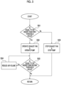
- Fig. 5 is a flowchart of ammonia removal processing in the first embodiment of the present disclosure.
- control device 48 when removing the ammonia inside the compartment 30 of the floating structure 1 described above will be described with reference to the flowchart in Fig. 5 .
- the exhaust fan control unit 72 and the pump control unit 73 of the control device 48 determine whether or not a concentration of ammonia inside the compartment 30 is equal to or higher than a predetermined first threshold value based on the detection result of the in-compartment sensor 46 (step S01).
- a concentration of ammonia inside the compartment 30 is not equal to or higher than the first threshold value, since there is no leakage of ammonia inside the compartment 30, the exhaust fan 42 and the pump 49 are set in a stop state (step S05).
- the exhaust fan control unit 72 starts operating the exhaust fan 42, and the pump control unit 73 starts operating the pump 49 (step S02) .
- the air inside the compartment 30 and the absorbing liquid are respectively supplied to the scrubber 44, and the ammonia inside the air is absorbed by the absorbing liquid.
- the ventilation exhaust fan 56 when the determination is made that the concentration of ammonia inside the compartment 30 is equal to or higher than the first threshold value, the ventilation exhaust fan 56 is set in a stop state, the ventilation exhaust damper 59 is closed, and the opening degree of the ventilation air supply damper 55 is regulated such that the inside of the compartment 30 is maintained at predetermined negative pressure.
- the exhaust fan control unit 72 of the control device 48 determines whether or not a concentration of ammonia in the absorbing liquid flowing through the absorbing liquid release line 45 is equal to or higher than a second threshold value based on the detection result of the release line sensor 47 (step S03). In this determination, the determination is made whether or not the concentration of ammonia in the absorbing liquid, which is released to the outside of the floating main structure 2 via the absorbing liquid release line 45, satisfies, for example, a rule related to ocean release. As a result of this determination, when the determination is made that the concentration of ammonia in the absorbing liquid flowing through the absorbing liquid release line 45 is not equal to or higher than the second threshold value, the process returns to step S01 (return).
- the air volume of the exhaust fan 42 is reduced by a predetermined amount, and the process returns to step S03. That is, the air volume of the exhaust fan 42 is reduced until the concentration of ammonia in the absorbing liquid flowing through the absorbing liquid release line 45 becomes less than a predetermined value.
- the floating structure 1 of the first embodiment includes: the floating main structure 2; the compartment 30 that is provided in the floating main structure 2 and that accommodates ammonia-related equipment inside the compartment 30; the duct 41 that is connected to the compartment 30 and that makes an inside of the compartment and an outside of the compartment 30 communicate with each other; the exhaust fan 42 that discharges the air at the inside of the compartment 30 to the outside of the compartment 30 via the duct 41; the absorbing liquid supply line 43 that supplies the absorbing liquid capable of absorbing the ammonia; the scrubber 44 that is disposed on the outside of the compartment 30 and that is capable of removing ammonia, which is contained in the air discharged by the exhaust fan 42 via the duct 41, by absorbing the ammonia with the absorbing liquid supplied through the absorbing liquid supply line 43; and the absorbing liquid release line 45 that releases at least the absorbing liquid, which has absorbed the ammonia in the scrubber 44, into water around which the floating main structure 2 floats.
- the ammonia can be removed by introducing the air that contains the ammonia leaked and vaporized inside the compartment 30 to the scrubber 44 via the duct 41. Further, since the absorbing liquid that has absorbed the ammonia in the scrubber 44 is released into water via the absorbing liquid release line 45, it is possible to prevent the ammonia contained in the absorbing liquid from re-vaporizing, being released into the atmosphere, and coming into contact with the worker. Furthermore, since the absorbing liquid that has absorbed ammonia does not remain inside the floating main structure 2, the contact between the absorbing liquid that has absorbed ammonia and the worker can be prevented. Therefore, it is possible to prevent the worker from coming into contact with the ammonia without flooding the equipment inside the compartment 30.
- the floating structure 1 of the first embodiment further includes the in-compartment sensor 46 that is capable of detecting the ammonia contained in the air at the inside of the compartment 30.
- the leakage of the ammonia inside the compartment 30 can be detected based on the detection result of the in-compartment sensor 46. Therefore, it is possible to operate the exhaust fan 42 to remove the ammonia only when the leakage of the ammonia occurs inside the compartment 30, and energy saving can be achieved.
- the floating structure 1 of the first embodiment further includes the release line sensor 47 capable of detecting the ammonia contained in the fluid flowing through the absorbing liquid release line 45.
- the flow rate of the air which is introduced from the compartment 30 to the scrubber 44, can be reduced to prevent the concentration of ammonia in the fluid discharged through the absorbing liquid release line 45 from exceeding a regulation value.
- the exhaust fan 42 of the floating structure 1 of the first embodiment is a variable speed fan capable of regulating the air volume.
- the floating structure 1 of the first embodiment includes the control device 48 that determines whether or not the leakage of the ammonia has occurred based on the detection result of the in-compartment sensor 46 and that operates the exhaust fan 42 when the determination is made that the leakage of the ammonia has occurred.
- the ammonia leaked inside the compartment 30 can be automatically removed by the control device 48.
- control device 48 of the first embodiment operates the exhaust fan 42 when a determination is made that the leakage of the ammonia has occurred and regulates the air volume of the exhaust fan 42 based on the detection result of the release line sensor 47.
- control device 48 can automatically prevent the concentration of ammonia contained in the fluid flowing through the absorbing liquid release line 45 from exceeding the regulation value.
- the control device 48 of the first embodiment further includes the ventilation exhaust fan 56 and the ventilation exhaust damper 59 that release the air at the inside of the compartment 30 to the outside of the floating main structure 2.
- the ventilation inside the compartment 30 can be performed by the ventilation exhaust fan 56.
- the second embodiment differs from the first embodiment described above only in a method of regulating the flow rate of the air flowing through the duct 41. Therefore, in the second embodiment, the same parts as those in the first embodiment described above will be described with the same reference numerals, and redundant descriptions will be omitted.
- Fig. 6 is a diagram corresponding to Fig. 2 in the second embodiment of the present disclosure.
- the floating structure 1 of the second embodiment includes the floating main structure 2, the superstructure 4, the combustion equipment 8, the ammonia tank 10, the pipe system 20, the compartment 30, and an ammonia removal system 240.
- the ammonia removal system 240 includes the duct 41, an exhaust fan 242, the absorbing liquid supply line 43, the scrubber (ammonia removal portion) 44, the absorbing liquid release line 45, the in-compartment sensor 46, the release line sensor 47, a circulation duct 81, a duct damper 82, a circulation duct damper 83, and a control device 248.
- the exhaust fan 242 discharges the air at the inside of the compartment 30 toward the outside of the compartment 30 via the duct 41.
- the exhaust fan 242 is provided in the duct 41 on a side closer to the first end portion 41a.
- the exhaust fan 242 of the present embodiment is a constant speed rotation fan that maintains a constant flow rate during steady operation. Switching control between operation and stop of the exhaust fan 242 is performed by the control device 248.
- the circulation duct 81 is branched and connected to the duct 41 which makes the compartment 30 and the scrubber 44 communicate with each other.
- the circulation duct 81 forms a flow path for returning the air flowing through the duct 41 to the compartment 30.
- the circulation duct 81 branches from the duct 41 between the exhaust fan 242 and the scrubber 44.
- the duct damper 82 is provided in the duct 41.
- the duct damper 82 is capable of regulating the flow rate of the air flowing inside the duct 41.
- the duct damper 82 is disposed closer to the scrubber 44 than a branch point P1 of the circulation duct 81.
- the duct damper 82 of the present embodiment is controlled by the control device 248.
- the circulation duct damper 83 is provided in the circulation duct 81.
- the circulation duct damper 83 is capable of regulating the flow rate of the air flowing inside the circulation duct 81.
- the circulation duct damper 83 of the present embodiment is controlled by the control device 248.
- the control device 248 controls the ammonia removal system 240. More specifically, the control device 248 determines whether or not the leakage of the ammonia has occurred, based on the detection result of the in-compartment sensor 46. Based on this determination, when the determination is made that the leakage of the ammonia has not occurred, the control device 248 sets the exhaust fan 242 in a stop state without operating the exhaust fan 242.
- the exhaust fan 242 may be constantly operated, and in this case, when the determination is made that the leakage of the ammonia has not occurred, the duct damper 82 may be set in a closed state, and the circulation duct damper 83 may be set in an open state.
- the control device 248 sets the exhaust fan 242 and the pump 49 in an operating state. Furthermore, the control device 248 controls the duct damper 82 and the circulation duct damper 83 based on the detection result of the release line sensor 47. More specifically, the control device 248 regulates the flow rate of the air flowing through the duct 41 and the flow rate of the air flowing through the circulation duct 81 by using the duct damper 82 and the circulation duct damper 83 based on the detection results of the release line sensor 47.
- the flow rate of the air flowing into the inside of the scrubber 44 is regulated by returning a part of the air sent by the exhaust fan 242 to the compartment 30. Since the hardware configuration of the control device 248 of the second embodiment is the same as that of the first embodiment, a detailed description thereof will be omitted.
- Fig. 7 is a functional block diagram of the control device described above.
- each functional configuration of the signal reception unit 71, an exhaust fan control unit 272, the pump control unit 73, the ventilation exhaust damper control unit 75, the ventilation air supply damper control unit 76, the ventilation exhaust fan control unit 77, a command signal output unit 278, a duct damper control unit 79, and a circulation duct damper control unit 80 is implemented.
- the signal reception unit 71, the pump control unit 73, the ventilation exhaust damper control unit 75, the ventilation air supply damper control unit 76, and the ventilation exhaust fan control unit 77 are the same as those of the control device 48 of the first embodiment described above.
- the exhaust fan control unit 272 controls the operation and stop of the exhaust fan 242 based on the detection signal of the in-compartment sensor 46 and the detection signal of the release line sensor 47 received by the signal reception unit 71.
- the duct damper control unit 79 controls an opening degree of the duct damper 82 based on the detection result of the release line sensor 47.
- the circulation duct damper control unit 80 controls an opening degree of the circulation duct damper 83 according to one or both of the opening degree of the duct damper 82 by the duct damper control unit 79 and the detection result of the release line sensor 47. Specifically, the circulation duct damper control unit 80 controls the opening degree of the circulation duct damper 83 such that the flow rate of the air flowing through the duct 41 becomes a flow rate in accordance with the opening degree of the duct damper 82.
- the command signal output unit 278 outputs command signals to each of the exhaust fan 42, the pump 49, the ventilation exhaust damper 59, the ventilation air supply damper 55, the ventilation exhaust fan 56, the duct damper 82, and the circulation duct damper 83 in order to implement each control by the exhaust fan control unit 272, the pump control unit 73, the ventilation exhaust damper control unit 75, the ventilation air supply damper control unit 76, the ventilation exhaust fan control unit 77, the duct damper control unit 79, and the circulation duct damper control unit 80.
- step S04 of the first embodiment described above the only difference from step S04 of the first embodiment described above is that the opening degrees of the respective duct damper 82 and the circulation duct damper 83 are changed to regulate the flow rate of the air flowing into the inside of the scrubber 44 via the duct 41, so a detailed explanation will be omitted.
- the ammonia can be removed by introducing the air that contains the ammonia leaked and vaporized inside the compartment 30 to the scrubber 44 via the duct 41. Further, since the absorbing liquid that has absorbed the ammonia in the scrubber 44 is released into water via the absorbing liquid release line 45, it is possible to prevent the ammonia contained in the absorbing liquid from re-vaporizing, being released into the atmosphere, and coming into contact with the worker. Furthermore, since the absorbing liquid that has absorbed ammonia does not remain inside the floating main structure 2, the contact between the absorbing liquid that has absorbed ammonia and the worker can be prevented. Therefore, it is possible to prevent the worker from coming into contact with the ammonia without flooding the equipment inside the compartment 30.
- the floating structure 1 of the second embodiment further includes: the circulation duct 81 that is branched and connected to the duct 41 and that returns the air flowing through the duct 41 to the compartment 30; the duct damper 82 that is provided in the duct 41 and that is capable of regulating the flow rate of the air flowing inside the duct 41; and the circulation duct damper 83 that is provided in the circulation duct 81 and that is capable of regulating the flow rate of the air flowing inside the circulation duct 81.
- the exhaust fan 242 is a constant speed fan that maintains a constant flow rate.
- the flow rate of the air flowing from the duct 41 into the inside of the scrubber 44 can be changed. Therefore, for example, when the concentration of ammonia contained in the fluid flowing through the absorbing liquid release line 45 is high, the flow rate of the air introduced into scrubber 44 can be reduced by increasing the flow rate of the air returned to compartment 30 by circulation duct 81. As a result, the concentration of ammonia in the fluid discharged through the absorbing liquid release line 45 can be prevented from exceeding the regulation value while using the constant speed fan as the exhaust fan 242.
- the floating structure 1 of the second embodiment further includes the control device 248 that controls the duct damper 82 and the circulation duct damper 83 based on the detection results of the in-compartment sensor 46 and the release line sensor 47.
- the control device 248 regulates the flow rate of the air flowing into the scrubber 44 by regulating the flow rate of the air flowing through the duct 41 and the flow rate of the air flowing through the circulation duct 81 by using the duct damper 82 and the circulation duct damper 83 based on the detection result of the release line sensor 47.
- control device 248 can automatically prevent the concentration of ammonia contained in the fluid flowing through the absorbing liquid release line 45 from exceeding the regulation value.
- the floating structure according to a third embodiment of the present disclosure will be described with reference to the drawings.
- the third embodiment is different only in that the exhaust fan of the first embodiment described above is also used as the ventilation exhaust fan. Therefore, in the third embodiment, the same parts as those in the first embodiment described above will be described with the same reference numerals, and redundant descriptions will be omitted.
- Fig. 8 is a diagram corresponding to Fig. 2 in the third embodiment of the present disclosure.
- the floating structure 1 of the third embodiment includes the floating main structure 2, the superstructure 4, the combustion equipment 8, the ammonia tank 10, the pipe system 20, the compartment 30, and an ammonia removal system 340.
- the ventilation air supply duct 53 for ventilating the inside of the compartment 30 is connected to the compartment 30, and the ventilation air supply damper 55 is provided in the ventilation air supply duct 53.
- the ammonia removal system 340 includes the duct 41, the exhaust fan 42, the absorbing liquid supply line 43, the scrubber (ammonia removal portion) 44, the absorbing liquid release line 45, the in-compartment sensor 46, the release line sensor 47, a ventilation exhaust duct 354, the duct damper 82, an exhaust duct damper 85, and a control device 348.
- the duct 41 has the same configuration as the duct 41 of the first embodiment and includes the first end portion 41a connected to the compartment 30 and the second end portion 41b connected to the scrubber 44.
- the duct 41 makes the internal space of the compartment 30 and the internal space of the scrubber 44 communicate with each other.
- the exhaust fan 42 has the same configuration as the exhaust fan 42 of the first embodiment.
- the exhaust fan 42 is a variable speed fan capable of regulating the air volume by the control device 348.
- the exhaust fan 42 is disposed in the vicinity of the first end portion 41a of the duct 41 on a side closer to the compartment 30 and discharges the air at the inside of the compartment 30 to the outside of the compartment 30 via the duct 41.
- the ventilation exhaust duct 354 is branched and connected to the duct 41.
- the ventilation exhaust duct 354 is configured to make the flow path inside the duct 41 and the outside of the floating main structure 2 communicate with each other and to be capable of discharging the air flowing through the duct 41 to the outside of the floating main structure 2.
- the duct damper 82 has the same configuration as the duct damper 82 of the second embodiment, is provided in the duct 41, and can regulate the flow rate of the air flowing inside the duct 41.
- the duct damper 82 in the third embodiment is disposed closer to the scrubber 44 than a branch point P2 between the duct 41 and the ventilation exhaust duct 354.
- the duct damper 82 is controlled by the control device 348.
- the exhaust duct damper 85 is provided in the ventilation exhaust duct 354 and can regulate the flow rate of the air flowing inside the ventilation exhaust duct 354.
- the exhaust duct damper 85 is controlled by the control device 348.
- the control device 348 controls the ammonia removal system 340.
- the control device 348 determines whether or not the leakage of the ammonia has occurred, based on the detection result of the in-compartment sensor 46. Based on this determination, when the determination is made that the leakage of the ammonia has not occurred, the control device 348 sets the air volume of the exhaust fan 42 to the air volume for ventilation. Further, the control device 348 sets the duct damper 82 in a closed state and sets the exhaust duct damper 85 in an open state.
- the control device 348 sets the pump 49 in an operating state, sets the duct damper 82 in an open state, and sets the exhaust duct damper 85 in an open state. Furthermore, the control device 348 of the third embodiment regulates the flow rate of the air flowing into the scrubber 44 by regulating the air volume of the exhaust fan 42 based on the detection result of the release line sensor 47. Since the hardware configuration of the control device 348 of the third embodiment is the same as that of the first embodiment, a detailed description thereof will be omitted.
- Fig. 9 is a functional block diagram of the control device described above.
- each functional configuration of the signal reception unit 71, an exhaust fan control unit 372, the pump control unit 73, the ventilation air supply damper control unit 76, a command signal output unit 378, the duct damper control unit 79, and an exhaust duct damper control unit 86 is implemented.
- the signal reception unit 71, the pump control unit 73, and the ventilation air supply damper control unit 76 have the same configuration as the control device 48 of the first embodiment described above.
- the exhaust fan control unit 372 controls the air volume of the exhaust fan 42 based on the detection signal of the in-compartment sensor 46 and the detection signal of the release line sensor 47 received by the signal reception unit 71. For example, when the determination is made that the leakage of the ammonia has not occurred inside the compartment 30 based on the detection result of the in-compartment sensor 46, the exhaust fan control unit 372 operates the exhaust fan 42 with an air volume for normal ventilation within the compartment 30 (hereinafter, referred to as a ventilation air volume) .
- the exhaust fan control unit 372 operates the exhaust fan 42 with an air volume for sending the air inside the compartment 30 to the scrubber 44 (hereinafter, referred to as a removing air volume).
- the duct damper control unit 79 controls the opening degree of the duct damper 82 based on the detection result of the in-compartment sensor 46. Specifically, the duct damper control unit 79 sets the duct damper 82 in an open state (for example, fully open) when the determination is made that the leakage of the ammonia has occurred inside the compartment 30 based on the detection result of the in-compartment sensor 46. On the other hand, the duct damper control unit 79 sets the duct damper 82 in a closed state (for example, fully closed) when the determination is made that the leakage of the ammonia has not occurred inside the compartment 30.
- an open state for example, fully open
- the duct damper control unit 79 sets the duct damper 82 in a closed state (for example, fully closed) when the determination is made that the leakage of the ammonia has not occurred inside the compartment 30.
- the exhaust duct damper control unit 86 controls an opening degree of the exhaust duct damper 85 based on the detection result of the in-compartment sensor 46. Specifically, the exhaust duct damper control unit 86 sets the exhaust duct damper 85 in a fully closed state when the determination is made that the leakage of the ammonia has occurred inside the compartment 30 based on the detection result of the in-compartment sensor 46. On the other hand, when the determination is made that the leakage of the ammonia has not occurred inside the compartment 30, the exhaust duct damper 85 is set in an open state (for example, fully open).
- the command signal output unit 378 outputs command signals to each of the exhaust fan 42, the pump 49, the ventilation air supply damper 55, the duct damper 82, and the exhaust duct damper 85 in order to implement each control by the signal reception unit 71, the exhaust fan control unit 372, the pump control unit 73, the ventilation air supply damper control unit 76, the command signal output unit 378, the duct damper control unit 79, and the exhaust duct damper control unit 86.
- Fig. 10 is a flowchart of the ammonia removal processing in an embodiment of the present disclosure.
- control device 348 when removing the ammonia inside the compartment 30 of the floating structure 1 described above will be described with reference to the flowchart in Fig. 10 .
- the exhaust fan control unit 72, the pump control unit 73, the duct damper control unit 79, and the exhaust duct damper control unit 86 of the control device 348 determine whether or not the concentration of ammonia inside the compartment 30 is equal to or higher than the predetermined first threshold value based on the detection result of the in-compartment sensor 46 (step S01).
- the duct damper control unit 79 sets the duct damper 82 in a closed state
- the exhaust duct damper control unit 86 sets the exhaust duct damper 85 in an open state (step S13).
- step S14 the exhaust fan control unit 72 operates the exhaust fan 42 with the ventilation air volume, and the pump control unit 73 sets the pump 49 in a stop state (step S14).
- the ventilation air supply damper control unit 76 sets the ventilation air supply damper 55 in an open state. As a result, the inside of the compartment 30 is ventilated. After that, the process returns to step S01.
- step S01 when the determination is made that the concentration of ammonia inside the compartment 30 is equal to or higher than the predetermined first threshold value, since there is the leakage of the ammonia inside the compartment 30, the duct damper control unit 79 sets the duct damper 82 in an open state, and the exhaust duct damper control unit 86 sets the exhaust duct damper 85 in a closed state (step S11) . Further, the exhaust fan control unit 72 operates the exhaust fan 42 with the removing air volume, and the pump control unit 73 operates the pump 49 (step S12). At this time, the ventilation air supply damper control unit 76 maintains the inside of the compartment 30 at predetermined negative pressure by regulating the opening degree of the ventilation air supply damper 55. As a result, the air inside the compartment 30 is sent inside the scrubber 44.
- the exhaust fan control unit 72 of the control device 348 determines whether or not a concentration of ammonia in the absorbing liquid flowing through the absorbing liquid release line 45 is equal to or higher than a second threshold value based on the detection result of the release line sensor 47 (step S03). In this determination, the determination is made whether or not the concentration of ammonia in the absorbing liquid, which is released to the outside of the floating main structure 2 via the absorbing liquid release line 45, satisfies, for example, a rule related to ocean release.
- the process returns to step S01.
- the air volume of the exhaust fan 42 is reduced by a predetermined amount, and the process returns to step S03. That is, the air volume of the exhaust fan 42 is reduced until the concentration of ammonia in the absorbing liquid flowing through the absorbing liquid release line 45 becomes less than a predetermined value.
- the ammonia can be removed by introducing the air that contains the ammonia leaked and vaporized inside the compartment 30 to the scrubber 44 via the duct 41. Further, since the absorbing liquid that has absorbed the ammonia in the scrubber 44 is released into water via the absorbing liquid release line 45, it is possible to prevent the ammonia contained in the absorbing liquid from re-vaporizing, being released into the atmosphere, and coming into contact with the worker. Furthermore, since the absorbing liquid that has absorbed ammonia does not remain inside the floating main structure 2, the contact between the absorbing liquid that has absorbed ammonia and the worker can be prevented. Therefore, it is possible to prevent the worker from coming into contact with the ammonia without flooding the equipment inside the compartment 30.
- the floating structure 1 of the third embodiment includes the ventilation exhaust duct 354, the duct damper 82, and the exhaust duct damper 85.
- a flow path which makes the inside of the compartment 30 and the outside of the ship communicate with each other
- a flow path which makes the inside of the compartment 30 and the inside of the scrubber 44 communicate with each other
- the exhaust fan 42 is provided in a common portion of the two flow paths that are switched and used, the compartment 30 can be ventilated or the air inside the compartment 30 can be sent to the scrubber 44 by using one exhaust fan 42. Therefore, the number of parts can be reduced as compared with a case where a ventilation fan and an ammonia removal fan are separately provided.
- the ventilation exhaust duct 54 and the ventilation exhaust fan 56 are omitted from the first embodiment described above. Therefore, in the fourth embodiment, the same parts as those in the first embodiment described above will be described with the same reference numerals, and redundant descriptions will be omitted.
- Fig. 11 is a diagram corresponding to Fig. 2 in the fourth embodiment of the present disclosure.
- the ammonia removal system 40 of the fourth embodiment includes a duct 41, an exhaust fan 42, an absorbing liquid supply line 43, a scrubber 44, an absorbing liquid release line 45, an in-compartment sensor 46, a release line sensor 47, and a control device 448.
- the ventilation air supply duct 53 for ventilating the inside of the compartment 30 is connected to the compartment 30. Further, the ventilation air supply damper 55 is attached to the ventilation air supply duct 53.
- the control device 448 has the same configuration as the control device 48 of the first embodiment described above, in that ammonia contained in the air inside the compartment 30 is removed by the scrubber 44.
- the control device 448 controls opening and closing of the opening-closing damper 58 based on the detection result of the in-compartment sensor 46.
- control device 448 switches between a state in which the opening-closing damper 58 is opened and the air inside the compartment 30 can be discharged to the outside of the floating main structure 2 via the duct 41, the scrubber 44, and the atmosphere release line 57, and a state in which the opening-closing damper 58 is closed, the air inside the compartment 30 has flowed inside the scrubber 44 to remove the ammonia, and the air is discharged from the absorbing liquid release line 45.
- Fig. 12 is a functional block diagram of the control device described above.
- each functional configuration of the signal reception unit 71, the exhaust fan control unit 72, the pump control unit 73, the ventilation air supply damper control unit 76, a command signal output unit 478, and an opening-closing damper control unit 87 is implemented.
- the opening-closing damper control unit 87 controls opening and closing of the opening-closing damper 58 based on the detection signal of the in-compartment sensor 46. Specifically, the opening-closing damper control unit 87 sets the opening-closing damper 58 in a closed state when the determination is made that the leakage of the ammonia has occurred inside the compartment 30 based on the detection result of the in-compartment sensor 46. On the other hand, the opening-closing damper control unit 87 sets the opening-closing damper 58 in an open state when the determination is made that the leakage of the ammonia has not occurred inside the compartment 30.
- the command signal output unit 478 outputs command signals to each of the exhaust fan 42, the pump 49, the ventilation air supply damper 55, and the opening-closing damper 58 in order to implement each control by the exhaust fan control unit 72, the pump control unit 73, the ventilation air supply damper control unit 76, and the opening-closing damper control unit 87.
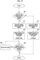
- Fig. 13 is a flowchart of the ammonia removal processing in the first embodiment of the present disclosure.
- step S11 in the flowchart shown in Fig. 10 of the third embodiment described above is replaced with step S21, and step S13 is replaced with step S23.
- the exhaust fan control unit 72, the pump control unit 73, the duct damper control unit 79, and the opening-closing damper control unit 87 of the control device 448 determine whether or not the concentration of ammonia inside the compartment 30 is equal to or higher than the predetermined first threshold value based on the detection result of the in-compartment sensor 46 (step S01).
- the opening-closing damper control unit 87 sets the opening-closing damper 58 in an open state (step S23).
- the exhaust fan control unit 72 operates the exhaust fan 42 with the ventilation air volume, and the pump control unit 73 sets the pump 49 in a stop state (step S14).
- the ventilation air supply damper control unit 76 sets the ventilation air supply damper 55 in an open state.
- the inside of the compartment 30 is ventilated via the ventilation air supply duct 53, the duct 41, the scrubber 44, and the atmosphere release line 57.
- the pump control unit 73 may continue the operation without stopping the pump 49.
- step S01 when the determination is made that the concentration of ammonia inside the compartment 30 is equal to or higher than the predetermined first threshold value, since there is the leakage of the ammonia inside the compartment 30, the duct damper control unit 79 sets the opening-closing damper 58 in a closed state (step S21). Further, the exhaust fan control unit 72 operates the exhaust fan 42 with the removing air volume, and the pump control unit 73 operates the pump 49 (step S12) . At this time, the ventilation air supply damper control unit 76 maintains the inside of the compartment 30 at predetermined negative pressure by regulating the opening degree of the ventilation air supply damper 55. As a result, the air inside the compartment 30 is sent inside the scrubber 44 but is not released to the atmosphere via the atmosphere release line 57. The description of step S03 and step S04 will be omitted because these steps are the same as those in the first embodiment described above.
- the ammonia can be removed by introducing the air that contains the ammonia leaked and vaporized inside the compartment 30 to the scrubber 44 via the duct 41. Further, since the absorbing liquid that has absorbed the ammonia in the scrubber 44 is released into water via the absorbing liquid release line 45, it is possible to prevent the ammonia contained in the absorbing liquid from re-vaporizing, being released into the atmosphere, and coming into contact with the worker. Furthermore, since the absorbing liquid that has absorbed ammonia does not remain inside the floating main structure 2, the contact between the absorbing liquid that has absorbed ammonia and the worker can be prevented. Therefore, it is possible to prevent the worker from coming into contact with the ammonia without flooding the equipment inside the compartment 30.
- the control device 448 of the fourth embodiment controls opening and closing of the opening-closing damper 58.
- the atmosphere release line 57 can be used instead of the ventilation exhaust duct by using one exhaust fan 42.
- the ventilation exhaust duct can be omitted. Therefore, the number of parts can be reduced as compared with a case where a ventilation fan and an ammonia removal fan are separately provided or a ventilation exhaust duct is provided.
- the inside of the compartment 30 can be ventilated, and the ammonia can be removed by sending the air inside the compartment 30 to the scrubber 44. Furthermore, when the leakage of the ammonia occurs, it is possible to prevent the air containing the ammonia from coming into contact with the worker.
- Fig. 14 is a diagram corresponding to Fig. 2 in a first modification example of the embodiment of the present disclosure.
- the ammonia removal system 40 of the first modification example includes a duct 41, an exhaust fan 42, an absorbing liquid supply line 43, a scrubber 44, an absorbing liquid release line 45, an in-compartment sensor 46, a release line sensor 47, the control device 48, and a heat exchanger 88.
- the heat exchanger 88 exchanges heat between the absorbing liquid flowing inside the absorbing liquid supply line 43 and an external heat medium to heat or cool the absorbing liquid.
- the heat exchanger 88 of the present modification example exchanges heat between the absorbing liquid and the heat medium such as heated water for heating the fuel ammonia in order to effectively use the cold energy of the fuel ammonia, for example, and reduces the temperature of the absorbing liquid.
- the absorbing liquid may be heated by using the heat exchanger 88.
- the absorption rate of ammonia can be improved by using the absorbing liquid, it is possible to reduce the energy consumed by the pump 49.
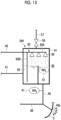
- Fig. 15 is an enlarged view of a scrubber in a second modification example of each embodiment of the present disclosure.
- the scrubber 244 in the second modification example is disposed at the outside of the compartment 30 in the same manner as the scrubber 44 described above.
- the scrubber 244 is configured to be capable of removing the ammonia, which is contained in the air discharged from the compartment 30 via the duct 41, by absorbing the ammonia with the absorbing liquid supplied through the absorbing liquid supply line 43.
- the scrubber 244 includes a scrubber casing 91, a liquid storage portion 92, a nozzle portion 50, and an internal absorbing liquid supply line 93.
- the scrubber casing 91 defines an internal space 95 of the scrubber 244.
- the liquid storage portion 92 is configured to be capable of storing the absorbing liquid in at least a part of the internal space 95.
- the liquid storage portion 92 of the second modification example forms a storing space for storing the absorbing liquid together with the scrubber casing 91.
- the liquid storage portion 92 is capable of making the absorbing liquid overflow from an upper portion thereof, and the overflowed absorbing liquid is discharged to the outside of the scrubber casing 91 through the absorbing liquid release line 45.
- the duct 41 is connected on a lower side of a liquid level of the liquid storage portion 92, and the air sent via the duct 41 is released into the absorbing liquid stored in the liquid storage portion 92 and moves upward as bubbles. The air that has reached the liquid level of the liquid storage portion 92 is released from the liquid level to inside the internal space 95.
- the internal absorbing liquid supply line 93 supplies the absorbing liquid to the nozzle portion 50 and the liquid storage portion 92.
- the internal absorbing liquid supply line 93 includes a main line 93A that supplies the absorbing liquid to the nozzle portion 50 and a branch line 93B that branches from the main line 93A and that reaches the liquid storage portion 92.
- the nozzle portion 50 is provided in an upper portion of the internal space 95 and sprays the absorbing liquid.
- the absorbing liquid which is sprayed from the nozzle portion 50, comes into contact with the air supplied to the internal space 95 via the liquid storage portion 92 while moving downward due to its own weight. Due to the contact, the ammonia contained in the air is absorbed in the absorbing liquid, reaches the lower portion of the internal space 95, and is discharged through the absorbing liquid release line 45 together with the overflowed absorbing liquid described above.
- a dilution water line 96 is provided.
- This dilution water line 96 is capable of sending the dilution water (for example, seawater or fresh water) with a dilution water pump (not shown) and allowing the dilution water to join the absorbing liquid release line 45.
- This dilution water pump (not shown) is a variable flow rate type pump, is controlled by, for example, the control devices 48, 248, 348, and 448, and allows the dilution water having a flow rate in accordance with the detection result of the release line sensor 47 to join the absorbing liquid release line 45.
- the flow rate of the dilution water can be controlled according to the concentration of discharged ammonia that is discharged from the absorbing liquid release line 45.
- the concentration of the discharged ammonia can be obtained by using the flow rate of the dilution water and the concentration of ammonia detected by an ammonia sensor.
- the dilution water line 96 in the second modification example may be appropriately provided or may be omitted. Since it is no longer necessary to provide the pump 49 with the flow rate of the diluted portion by providing this configuration of the dilution water line 96, it becomes possible to downsize the pump 49. Furthermore, the dilution water pump (not shown) in the second modification example is not limited to the variable flow rate type and may be, for example, a type of pump capable of supplying a constant flow rate at the maximum flow rate.
- the release line sensor 47 provided in the absorbing liquid release line 45 as the ammonia sensor has been described as an example, an internal space sensor 97 that is provided in a space of the internal space 95 excluding the liquid storage portion 92 may be used, for example.
- the liquid storage portion 92 may be disposed outside the scrubber casing 91.
- an overflow pipe of the liquid storage portion 92 may be connected to the scrubber casing 91, and the gas phase of the liquid storage portion 92 and the gas phase of the scrubber casing 91 may be made to communicate with each other through a pipe or the like.
- the air sent via the duct 41 can be brought into contact with the absorbing liquid without fail, the air from which ammonia has not been sufficiently removed can be prevented from being discharged from the absorbing liquid release line 45.
- the atmosphere release line 57 and the opening-closing damper 58 may be omitted.
- control devices 48, 248, 348, and 448 automatically remove the ammonia by the scrubber 44 when the determination is made that the leakage of the ammonia has occurred inside the compartment 30
- the control devices 48, 248, 348, and 448 may be omitted, and for example, the worker may operate the exhaust fans 42 and 242 or the like by visually observing the detection result of the in-compartment sensor 46 on a display device, and then the ammonia inside the compartment 30 may be removed.
- a dedicated pump 49 for supplying the absorbing liquid to the scrubber 44 via the absorbing liquid supply line 43 has been described.
- the pump 49 which supplies the absorbing liquid may also be used as another seawater or fresh water pump provided in the floating main structure 2.
- the pump 49 is operated when the determination is made that the leakage of the ammonia has occurred and is in a stop state in other cases, the pump 49 may be in a constantly operating state.
- the dilution water line 96 of this second modification example may be provided for the first to fourth embodiments and the first modification example as appropriate.
- control devices 48, 248, 348, and 448 a case where a computer device is used as the control devices 48, 248, 348, and 448 has been described as an example.
- the functional configurations of the control devices 48, 248, 348, and 448 may be implemented by hardware such as a relay circuit, or the functional configurations of the control devices 48, 248, 348, and 448 may be implemented by a combination of hardware and software.
- the floating structure 1 described in the embodiment is ascertained as follows, for example.
- ammonia removal portion 44 examples include a scrubber.
- the ammonia can be removed by introducing the air that contains the ammonia leaked and vaporized inside the compartment 30 to the ammonia removal portion 44 via the duct 41. Further, since the absorbing liquid that has absorbed the ammonia in the ammonia removal portion 44 is released into water via the absorbing liquid release line 45, it is possible to prevent the ammonia contained in the absorbing liquid from re-vaporizing, being released into the atmosphere, and coming into contact with the worker. Furthermore, since the absorbing liquid that has absorbed ammonia does not remain inside the floating main structure 2, the contact between the absorbing liquid that has absorbed ammonia and the worker can be prevented. Therefore, it is possible to prevent the worker from coming into contact with the ammonia without flooding the equipment inside the compartment 30.
- the floating structure 1 according to a second aspect is the floating structure 1 of (1), the floating structure 1 further includes an in-compartment sensor 46 that is capable of detecting ammonia contained in the air at the inside of the compartment 30.
- the leakage of the ammonia inside the compartment 30 can be detected based on the detection result of the in-compartment sensor 46.
- the floating structure 1 according to a third aspect is the floating structure 1 of (2), the floating structure 1 further includes a release line sensor 47 that is capable of detecting ammonia contained in fluid flowing through the absorbing liquid release line 45.
- the flow rate of the air which is introduced from the compartment 30 to the scrubber 44, can be reduced to prevent the concentration of ammonia in the fluid discharged through the absorbing liquid release line 45 from exceeding a regulation value.
- the floating structure 1 according to a fourth aspect is the floating structure 1 of (3), in which the exhaust fan 42 is a variable speed fan that is capable of regulating an air volume.
- the concentration of ammonia contained in the fluid flowing through the absorbing liquid release line 45 is high, by reducing the air volume of the exhaust fan 42 according to the concentration of ammonia, the concentration of ammonia in the fluid flowing through the absorbing liquid release line 45 can be reduced.
- the floating structure 1 is the floating structure 1 of any one of (2) to (4), the floating structure 1 further includes a control device 48, 248, 348, 448 that determines whether or not leakage of the ammonia has occurred based on a detection result of the in-compartment sensor 46 and that operates the exhaust fan 42, 242 when a determination is made that the leakage of the ammonia has occurred.
- the ammonia leaked inside the compartment 30 can be automatically removed by the control device 48, 248, 348, 448.
- the floating structure 1 is the floating structure 1 of (5), the floating structure 1 further includes a control device 48, 248, 348, 448 that determines whether or not leakage of the ammonia has occurred based on a detection result of the in-compartment sensor 46, that operates the exhaust fan 42, 242 when a determination is made that the leakage of the ammonia has occurred, and that regulates an air volume of the exhaust fan 42, 242 based on a detection result of the release line sensor 47.
- a control device 48, 248, 348, 448 that determines whether or not leakage of the ammonia has occurred based on a detection result of the in-compartment sensor 46, that operates the exhaust fan 42, 242 when a determination is made that the leakage of the ammonia has occurred, and that regulates an air volume of the exhaust fan 42, 242 based on a detection result of the release line sensor 47.
- the concentration of ammonia contained in the fluid flowing through the absorbing liquid release line 45 can be automatically prevented from exceeding the regulation value.
- the floating structure 1 is the floating structure 1 of (3), the floating structure 1 further includes: a circulation duct 81 that is branched and connected to the duct 41 and that returns the air flowing through the duct 41 to the compartment 30; a duct damper 82 that is provided in the duct 41 and that is capable of regulating a flow rate of the air flowing inside the duct 41; and a circulation duct damper 83 that is provided in the circulation duct 81 and that is capable of regulating a flow rate of the air flowing inside the circulation duct 81, in which the exhaust fan 242 is a constant speed fan that maintains a constant flow rate.
- the flow rate of the air flowing from the duct 41 into the inside of the scrubber 44 can be changed. Therefore, for example, when the concentration of ammonia contained in the fluid flowing through the absorbing liquid release line 45 is high, the flow rate of the air, which is introduced from the compartment 30 to the scrubber 44, can be reduced to prevent the concentration of ammonia in the fluid discharged through the absorbing liquid release line 45 from exceeding a regulation value.
- the floating structure 1 is the floating structure 1 of (7), the floating structure 1 further includes a control device that controls the duct damper and the circulation duct damper based on detection results of the in-compartment sensor and the release line sensor, in which the control device sets the duct damper in a closed state and sets the circulation duct damper in an open state when a determination is made that leakage of the ammonia has not occurred based on the detection result of the in-compartment sensor, and regulates a flow rate of the air flowing into the ammonia removal portion by regulating the flow rate of the air flowing through the duct and the flow rate of the air flowing through the circulation duct by using the duct damper and the circulation duct damper based on the detection result of the release line sensor when a determination is made that leakage of the ammonia has occurred.
- the control device 248 can automatically prevent the concentration of ammonia contained in the fluid flowing through the absorbing liquid release line 45 from exceeding the regulation value.
- the floating structure 1 is the floating structure 1 of any one of (1) to (8), the floating structure 1 further includes a ventilation exhaust fan 56 that releases the air at the inside of the compartment 30 to an outside of the floating main structure 2.
- the ventilation inside the compartment 30 can be performed by the ventilation exhaust fan 56.
- the floating structure 1 is the floating structure 1 of (1), the floating structure 1 further includes: a ventilation exhaust duct 354 that is branched and connected to the duct 41 and that discharges the air flowing through the duct 41 to an outside of the floating main structure 2; a duct damper 82 that is provided in the duct 41 and that is capable of regulating a flow rate of the air flowing inside the duct 41; and an exhaust duct damper 85 that is provided in the ventilation exhaust duct 354 and that is capable of regulating a flow rate of the air flowing inside the ventilation exhaust duct 354.
- a flow path which is configured with the duct 41 and the ventilation exhaust duct 354 and makes the inside of the compartment 30 and the outside of the ship communicate with each other
- a flow path which is configured with the duct 41 and makes the inside of the compartment 30 and the inside of the scrubber 44 communicate with each other
- the exhaust fan 42 is provided in a common portion of the two flow paths that are switched and used, the compartment 30 can be ventilated or the air inside the compartment 30 can be sent to the scrubber 44 by using one exhaust fan 42. Therefore, the number of parts can be reduced as compared with a case where a ventilation fan and an ammonia removal fan are separately provided.
- the floating structure 1 according to an eleventh aspect is the floating structure 1 of (10), the floating structure 1 further includes an in-compartment sensor 46 that is capable of detecting ammonia contained in the air at the inside of the compartment 30.
- the leakage of the ammonia inside the compartment 30 can be detected based on the detection result of the in-compartment sensor 46, it is possible to switch to the flow path, which is configured with the duct 41 and makes the inside of the compartment 30 and the inside of the scrubber 44 communicate with each other, when the determination is made that the leakage of the ammonia has occurred. Therefore, it is possible to further prevent the worker from coming into contact with the ammonia.
- the floating structure 1 is the floating structure 1 of (11), the floating structure 1 further includes a control device 348 that controls the duct damper 82 and the exhaust duct damper 85 based on a detection result of the in-compartment sensor 46, in which the control device 348 sets the duct damper 82 in a closed state and sets the exhaust duct damper 85 in an open state when a determination is made that leakage of the ammonia has not occurred, and sets the duct damper 82 in an open state and sets the exhaust duct damper 85 in a closed state when the determination is made that the leakage of the ammonia has occurred.
- the ammonia leaked inside the compartment 30 can be automatically removed.
- the floating structure 1 according to a thirteenth aspect is the floating structure 1 of (12), in which the exhaust fan 42 is a variable speed fan that is capable of regulating an air volume.
- the concentration of ammonia contained in the fluid flowing through the absorbing liquid release line 45 is high, by reducing the air volume of the exhaust fan 42 according to the concentration of ammonia, the concentration of ammonia in the fluid flowing through the absorbing liquid release line 45 can be reduced.
- the floating structure 1 is the floating structure 1 of (13), the floating structure 1 further includes a release line sensor 47 that is capable of detecting ammonia contained in fluid flowing through the absorbing liquid release line 45, in which the control device 348 regulates the air volume of the exhaust fan 42 based on a detection result of the release line sensor 47.
- the concentration of ammonia contained in the fluid flowing through the absorbing liquid release line 45 can be automatically prevented from exceeding the regulation value.
- the floating structure 1 is the floating structure 1 of (2), in which the ammonia removal portion 44 includes an atmosphere release line 57 that is capable of releasing the air, which has flowed into an inside of the ammonia removal portion 44 via the duct 41, to the atmosphere, and an opening-closing damper 58 that opens and closes the atmosphere release line 57.
- the atmosphere release line 57 can be used instead of the ventilation exhaust duct. Therefore, the compartment 30 can be ventilated or the air at the inside of the compartment 30 can be sent to the scrubber 44 to remove the ammonia while reducing the number of parts as compared with a case where a ventilation fan and an ammonia removal fan are separately provided. Furthermore, when the leakage of the ammonia occurs, it is possible to prevent the air containing the ammonia from coming into contact with the worker.
- the floating structure 1 according to a sixteenth aspect is the floating structure 1 of (15), the floating structure 1 further includes a control device 448 that controls opening and closing of the opening-closing damper 58 based on the detection result of the in-compartment sensor 46.
- the ammonia leaked inside the compartment 30 can be automatically removed.
- the floating structure 1 according to a seventeenth aspect is the floating structure 1 of (16), the floating structure 1 further includes a release line sensor 47 that is capable of detecting ammonia contained in fluid flowing through the absorbing liquid release line, in which the exhaust fan 42 is a variable speed fan that is capable of regulating an air volume, and the control device 448 regulates the air volume of the exhaust fan 42 based on a detection result of the release line sensor 47.
- the concentration of ammonia contained in the fluid flowing through the absorbing liquid release line 45 can be automatically prevented from exceeding the regulation value.
- the floating structure 1 is the floating structure 1 of any one of (1) to (17), the floating structure 1 further includes a heat exchanger 88 that is capable of heating or cooling the absorbing liquid.
Landscapes
- Engineering & Computer Science (AREA)
- Chemical & Material Sciences (AREA)
- Combustion & Propulsion (AREA)
- Ocean & Marine Engineering (AREA)
- Mechanical Engineering (AREA)
- Environmental & Geological Engineering (AREA)
- Biomedical Technology (AREA)
- Oil, Petroleum & Natural Gas (AREA)
- Chemical Kinetics & Catalysis (AREA)
- General Chemical & Material Sciences (AREA)
- Analytical Chemistry (AREA)
- Health & Medical Sciences (AREA)
- Treating Waste Gases (AREA)
Applications Claiming Priority (2)
| Application Number | Priority Date | Filing Date | Title |
|---|---|---|---|
| JP2021113523A JP7784836B2 (ja) | 2021-07-08 | 2021-07-08 | 浮体 |
| PCT/JP2022/018012 WO2023281896A1 (ja) | 2021-07-08 | 2022-04-18 | 浮体 |
Publications (2)
| Publication Number | Publication Date |
|---|---|
| EP4368488A1 true EP4368488A1 (de) | 2024-05-15 |
| EP4368488A4 EP4368488A4 (de) | 2024-10-02 |
Family
ID=84801452
Family Applications (1)
| Application Number | Title | Priority Date | Filing Date |
|---|---|---|---|
| EP22837317.1A Pending EP4368488A4 (de) | 2021-07-08 | 2022-04-18 | Schwimmkörper |
Country Status (5)
| Country | Link |
|---|---|
| EP (1) | EP4368488A4 (de) |
| JP (1) | JP7784836B2 (de) |
| KR (1) | KR20240016407A (de) |
| CN (1) | CN117580761A (de) |
| WO (1) | WO2023281896A1 (de) |
Families Citing this family (2)
| Publication number | Priority date | Publication date | Assignee | Title |
|---|---|---|---|---|
| WO2025206891A1 (ko) * | 2024-03-26 | 2025-10-02 | 에이치디현대중공업 주식회사 | 연료 처리 시스템 및 이를 포함하는 선박 |
| JP7703117B1 (ja) * | 2025-01-29 | 2025-07-04 | 三菱造船株式会社 | 船舶、船舶における操舵室の空気調和方法 |
Family Cites Families (11)
| Publication number | Priority date | Publication date | Assignee | Title |
|---|---|---|---|---|
| JP3078789B2 (ja) | 1998-11-16 | 2000-08-21 | 株式会社前川製作所 | アンモニア冷媒を使用した船舶用冷凍/空調装置 |
| JP2006026555A (ja) * | 2004-07-16 | 2006-02-02 | Hachiyo Engneering Kk | アンモニアガスの除害システム |
| JP4356939B2 (ja) | 2005-05-16 | 2009-11-04 | 株式会社前川製作所 | 漏洩アンモニア除害方法及び装置 |
| JP2010210129A (ja) | 2009-03-09 | 2010-09-24 | Toyo Eng Works Ltd | 冷却システム |
| JP5839791B2 (ja) * | 2010-10-14 | 2016-01-06 | 三菱重工業株式会社 | 舶用scr還元剤供給システム |
| EP2955345B1 (de) * | 2013-01-30 | 2019-12-18 | Fuji Electric Co., Ltd. | Abgasbehandlungssystem für schiffsdieselmotor |
| EP3502457B1 (de) | 2016-10-25 | 2021-06-09 | Imabari Shipbuilding Co., Ltd. | Schiff mit gasrohrleitungssystem-installation |
| KR102745935B1 (ko) * | 2019-12-04 | 2024-12-20 | 한화엔진 주식회사 | 암모니아 공급 시스템 |
| JP2021113523A (ja) | 2020-01-20 | 2021-08-05 | トヨタ紡織株式会社 | 吸気系ダクトの組付け構造 |
| CN111392019B (zh) | 2020-03-27 | 2022-04-08 | 大连船舶重工集团有限公司 | 一种清洁排放的船舶动力系统 |
| CN112696289B (zh) | 2020-12-28 | 2024-07-26 | 大连船舶重工集团有限公司 | 一种船用液氨燃料供给及燃料回收利用系统 |
-
2021
- 2021-07-08 JP JP2021113523A patent/JP7784836B2/ja active Active
-
2022
- 2022-04-18 CN CN202280046687.5A patent/CN117580761A/zh active Pending
- 2022-04-18 WO PCT/JP2022/018012 patent/WO2023281896A1/ja not_active Ceased
- 2022-04-18 KR KR1020247000039A patent/KR20240016407A/ko active Pending
- 2022-04-18 EP EP22837317.1A patent/EP4368488A4/de active Pending
Also Published As
| Publication number | Publication date |
|---|---|
| WO2023281896A1 (ja) | 2023-01-12 |
| JP2023009884A (ja) | 2023-01-20 |
| EP4368488A4 (de) | 2024-10-02 |
| JP7784836B2 (ja) | 2025-12-12 |
| KR20240016407A (ko) | 2024-02-06 |
| CN117580761A (zh) | 2024-02-20 |
Similar Documents
| Publication | Publication Date | Title |
|---|---|---|
| EP4368488A1 (de) | Schwimmkörper | |
| CN103228881B (zh) | 船舶用scr还原剂供给系统、船舶用废气脱硝装置以及船舶 | |
| US12428118B2 (en) | Fuel cell ship | |
| JP7808952B2 (ja) | 浮体 | |
| KR101035319B1 (ko) | 연료전지시스템 및 그 정지방법 | |
| EP4538168A1 (de) | Schwimmkörper | |
| US12502967B2 (en) | Fuel cell ship | |
| JP7716935B2 (ja) | 浮体 | |
| KR20230145181A (ko) | 선박 | |
| JP2025168407A (ja) | 燃料電池船 | |
| JP2014085265A (ja) | 冷却システム | |
| EP4098551A2 (de) | Brennstoffzellenschiff | |
| EP4563214A1 (de) | Wäscher und gasbehandlungsverfahren in wäscher | |
| WO2024053600A1 (ja) | 浮体、浮体のアンモニア処理方法 | |
| KR20220163867A (ko) | 연료 전지선 | |
| US12552271B2 (en) | Fuel cell ship | |
| JP7815320B2 (ja) | 発電システム | |
| KR20240171837A (ko) | 선박 | |
| KR20250144240A (ko) | 선박 | |
| EP4682357A1 (de) | Ammoniakentlüftungsgasbehandlungssystem und abgasbehandlungsverfahren damit | |
| KR20210138943A (ko) | 공기윤활시스템이 적용된 선박의 소화시스템 | |
| JP2023128409A (ja) | 燃料電池の排水装置及び燃料電池システム |
Legal Events
| Date | Code | Title | Description |
|---|---|---|---|
| STAA | Information on the status of an ep patent application or granted ep patent |
Free format text: STATUS: THE INTERNATIONAL PUBLICATION HAS BEEN MADE |
|
| PUAI | Public reference made under article 153(3) epc to a published international application that has entered the european phase |
Free format text: ORIGINAL CODE: 0009012 |
|
| STAA | Information on the status of an ep patent application or granted ep patent |
Free format text: STATUS: REQUEST FOR EXAMINATION WAS MADE |
|
| 17P | Request for examination filed |
Effective date: 20240102 |
|
| AK | Designated contracting states |
Kind code of ref document: A1 Designated state(s): AL AT BE BG CH CY CZ DE DK EE ES FI FR GB GR HR HU IE IS IT LI LT LU LV MC MK MT NL NO PL PT RO RS SE SI SK SM TR |
|
| A4 | Supplementary search report drawn up and despatched |
Effective date: 20240902 |
|
| RIC1 | Information provided on ipc code assigned before grant |
Ipc: B63H 21/38 20060101ALI20240827BHEP Ipc: B63J 2/10 20060101ALI20240827BHEP Ipc: B63J 2/08 20060101ALI20240827BHEP Ipc: B63J 2/06 20060101ALI20240827BHEP Ipc: B63B 25/16 20060101ALI20240827BHEP Ipc: B63B 11/04 20060101AFI20240827BHEP |
|
| DAV | Request for validation of the european patent (deleted) | ||
| DAX | Request for extension of the european patent (deleted) | ||
| STAA | Information on the status of an ep patent application or granted ep patent |
Free format text: STATUS: EXAMINATION IS IN PROGRESS |
|
| 17Q | First examination report despatched |
Effective date: 20250828 |