EP4367314B1 - Gerät zur behandlung von wäsche mit dampf mit einer basis, die dazu bestimmt ist, auf einer unterlage zu ruhen - Google Patents
Gerät zur behandlung von wäsche mit dampf mit einer basis, die dazu bestimmt ist, auf einer unterlage zu ruhen Download PDFInfo
- Publication number
- EP4367314B1 EP4367314B1 EP22743798.5A EP22743798A EP4367314B1 EP 4367314 B1 EP4367314 B1 EP 4367314B1 EP 22743798 A EP22743798 A EP 22743798A EP 4367314 B1 EP4367314 B1 EP 4367314B1
- Authority
- EP
- European Patent Office
- Prior art keywords
- base
- stable operating
- operating position
- steam generator
- vaporisation
- Prior art date
- Legal status (The legal status is an assumption and is not a legal conclusion. Google has not performed a legal analysis and makes no representation as to the accuracy of the status listed.)
- Active
Links
Images



Classifications
-
- D—TEXTILES; PAPER
- D06—TREATMENT OF TEXTILES OR THE LIKE; LAUNDERING; FLEXIBLE MATERIALS NOT OTHERWISE PROVIDED FOR
- D06F—LAUNDERING, DRYING, IRONING, PRESSING OR FOLDING TEXTILE ARTICLES
- D06F73/00—Apparatus for smoothing or removing creases from garments or other textile articles by formers, cores, stretchers, or internal frames, with the application of heat or steam
-
- D—TEXTILES; PAPER
- D06—TREATMENT OF TEXTILES OR THE LIKE; LAUNDERING; FLEXIBLE MATERIALS NOT OTHERWISE PROVIDED FOR
- D06F—LAUNDERING, DRYING, IRONING, PRESSING OR FOLDING TEXTILE ARTICLES
- D06F75/00—Hand irons
- D06F75/08—Hand irons internally heated by electricity
- D06F75/10—Hand irons internally heated by electricity with means for supplying steam to the article being ironed
- D06F75/12—Hand irons internally heated by electricity with means for supplying steam to the article being ironed the steam being produced from water supplied to the iron from an external source
Definitions
- the present invention relates to the field of devices for steaming laundry comprising a base intended to rest on a support in which the base comprises a steam generator connected by a conduit to an ironing and/or steaming tool.
- the base of such a device has the disadvantage of only being able to be arranged in a single stable operating position, in which the base extends predominantly vertically. In this position, the height of the base is relatively large so that it is suitable for positioning the base on the floor but does not provide optimal ergonomics of use when the base is arranged at a height, for example on an ironing board, the risk of the base tipping to the side when traction is exerted laterally on the flexible conduit being significant.
- the present invention aims to remedy this drawback.
- the invention relates to an apparatus for steam treating laundry comprising a base intended to rest on a support, the base comprising a steam generator and being connected by a conduit to an ironing and/or steaming tool, said base having a shape and/or first appendages adapted to allow the base to rest on the support in a first stable operating position in which the base has a first inclination relative to said support, characterized in that the base has a shape or second appendages adapted to allow the base to rest on the support in a second stable operating position, in which the base has an inclination relative to the support different from that which it has when it rests in the first stable operating position, and in that the steam generator comprises an instantaneous vaporization chamber having a shape adapted to vaporize the water injected into the steam generator in the first and second stable operating position.
- the user can choose to place the device in one of the two stable operating positions offered depending on where the base is placed in order to improve the ergonomics of use.
- the device may further have one or more of the following features, taken alone or in combination.
- the vaporization chamber has a shape adapted so that the difference in vaporization performance between the two stable operating positions is less than 20%.
- Vaporization performance means the maximum steam flow rate that the steam generator is capable of providing in the stable operating position.
- the vaporization chamber comprises a first vaporization surface onto which the water is projected in the first stable operating position and a second vaporization surface onto which the water is projected in the second stable operating position, the first vaporization surface being distinct from the second vaporization surface.
- the steam generator comprises a body enclosing the vaporization chamber and the first vaporization surface and the second vaporization surface are arranged respectively on a first face and on a second face of the body which form between them an angle ⁇ of between 45° and 135°, and preferably of between 50° and 90°.
- the two faces of the generator meet at a common edge.
- the first vaporization surface and the second vaporization surface are arranged symmetrically with respect to a plane P passing through the common edge.
- the two faces of the steam generator are heated by the same electric heating resistor which has a curved part at the common edge.
- the first vaporization surface is equipped with a first temperature sensor and the second vaporization surface is equipped with a second temperature sensor, the first temperature sensor serving to regulate the electrical supply of the heating resistor when the base occupies the first stable operating position and the second temperature sensor serving to regulate the supply of the heating resistor when the base occupies the second stable operating position.
- the steam generator comprises at least one water inlet orifice allowing the introduction of water into the steam generator and at least one steam outlet orifice allowing the diffusion of steam towards the ironing and/or steaming tool, the base comprising a reservoir and a pump allowing water to be supplied to said at least one water inlet orifice.
- the base comprises a handle to facilitate its transport and, in the first stable operating position, the handle is arranged at the top of the base, and in the second stable operating position, the handle is arranged on the side of the base.
- the steam outlet orifice is connected by the conduit to the tool.
- the water inlet orifice and the steam outlet orifice are arranged on the same face of the steam generator.
- the vaporization chamber comprises two water inlet orifices provided on the same face of the steam generator.
- the base comprises a first series of feet on which it rests when it occupies the first stable operating position and a second series of feet on which it rests when it occupies the second stable operating position.
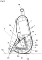
- THE figures 1 And 2 represent a steam ironing device comprising a portable base 1 connected to a steam iron 2 by a flexible conduit 3, partially illustrated in the figures, the base 1 itself being electrically connected to a domestic network by a cable, not visible in the figures.
- the iron 2 comprises, in a manner known per se, a flat soleplate, having a pointed front end, surmounted by a housing comprising a grip handle 20 having a free rear end projecting laterally.
- the housing of the iron 2 contains a casting maintained in thermal contact with the soleplate and which comprises a heating resistor 9, regulated by means of a non-adjustable thermostat, making it possible to maintain the temperature of the soleplate around a set temperature of the order of 135°C.
- the base 1 of the device comprises a housing 10 in which the iron 2 can be placed for storage, the housing 10 being advantageously formed by a cavity which is delimited laterally by a peripheral wall 10A which follows the general outline of the iron 2 and has a projecting lower end 12C.
- the base 1 also comprises a sheath 11 for storing the flexible conduit 3 and a handle 14 for gripping the base 1 to facilitate its transport.
- the base 1 of the device is provided with a first series of feet 12A, 12B, 12C allowing the base 1 to rest on a support 100, such as a table or the floor, in a first stable operating position, illustrated in the figures 1 And 2 , also called vertical position, in which the base 1 extends substantially vertically with the handle 14 located substantially at the top of the base 1.
- This first series of feet 12A, 12B, 12C is advantageously constituted by two pads 12A, 12B which project from a lower face of the base 1 and by the lower end 12C projecting from the receiving housing 10 which receives the front tip of the soleplate of the iron 2.
- the base 1 is also provided with a second series of feet 13A, 13B, 13C allowing the base 1 to rest on the support 100 in a second position.
- stable operation illustrated on the [ Fig. 3 ], also called horizontal position, in which base 1 extends substantially horizontally with the handle 14 located on one side of the base 1.
- This second series of feet 13A, 13B, 13C is advantageously constituted by three pads which project on a lateral face of the base 1, as can be seen in the [ Fig.4 ].
- the base 1 contains a reservoir 4, a pump 5, shown schematically, and a steam generator 6, the pump 5 drawing water from the reservoir 4 to send it to the steam generator 6.
- the steam generator 6 contains an instantaneous vaporization chamber 7 into which water from the reservoir 4 is injected by the pump 5.
- the operation of the pump 5 is controlled by a trigger 21 arranged under the front end of the grip handle 20, the pump 5 being advantageously sized to provide a flow rate of the order of 40 gr/min continuously when the trigger 21 is actuated.
- the vaporization chamber 7 is integrated into an aluminum body 60 having the shape of a polyhedron with an open face, the latter receiving a closing cover 8 comprising two water inlet orifices 8A, 8B and a steam outlet orifice 8C opening directly into the vaporization chamber 7.
- the steam outlet orifice 8C is arranged in a central position on the closing cover 8, the water inlet orifices 8A, 8B being arranged symmetrically on either side of the steam outlet orifice 8C.
- the vaporization chamber 7 comprises a first vaporization surface 70 onto which the water is projected in the first stable operating position.
- This first vaporization surface 70 is arranged on a first face 60A of the body 60 which faces the closing cover 8.
- the vaporization chamber 7 comprises a second vaporization surface 71 onto which the water is projected in the second stable operating position.
- This second vaporization surface 71 is arranged on a second face 60B of the body 60 which is arranged laterally to the closing cover 8.
- the first face 60A and the second face 60B of the body 60 of the steam generator 6 are generally planar and meet at a common edge 60C forming an acute angle.
- the first face 60A and the second face 60B of the body 60 extend respectively along a longitudinal axis A1 and along a longitudinal axis A2 which form between them an angle ⁇ advantageously between 50° and 90° and preferably of the order of 70°, the first vaporization surface 70 and the second vaporization surface 71 being arranged symmetrically with respect to a plane P passing through the common edge 60C.
- the steam generator 6 is fixed in the base 1 so that the first vaporization surface 70, and in particular its longitudinal axis A1, is inclined by the order of 3° in the direction of the common edge 60C relative to the horizontal plane when the base 1 occupies the vertical operating position.
- the geometry of the steam generator 6 is such that the second vaporization surface 71, and in particular its longitudinal axis A2, is also inclined by the order of 3° in the direction of the common edge 60C relative to the horizontal plane when the base 1 occupies the horizontal operating position.
- the first vaporization surface 70 or the second vaporization surface 71 onto which the water from the water inlet orifices 8A, 8B is projected is inclined towards the common edge 60C.
- the body 60 of the steam generator 6 comprises an electrical heating resistor 9 which extends along the edges of the first vaporization surface 70 and the second vaporization surface 71.
- the heating resistor 9 has two ends 90 which project from the face of the body 60 opposite the second face 60B and which allow the electrical connection of the heating resistor 9, the heating resistor 9 also comprising a bent portion at the common edge 60C, and a U-shaped portion which extends along the periphery of the second face 60B of the body 60.
- the electrical power supply to the heating resistor 9 is regulated by means of a power supply circuit comprising a first temperature sensor 91 arranged on the back of the first face 60A, and a second temperature sensor 92 arranged on the back of the second face 60B, the first and second temperature sensors 91, 92 being connected to a control unit, not illustrated in the figures, which supplies the heating resistor 9 as a function of the data supplied by the two temperature sensors 91, 92.
- a control unit not illustrated in the figures, which supplies the heating resistor 9 as a function of the data supplied by the two temperature sensors 91, 92.
- Such an arrangement of the temperature sensors 91, 92 has the advantage of allowing the temperature of each of the first and second vaporization surfaces 70, 71 to be read so that the control unit can react quickly to the drop in temperature on one or other of these vaporization surfaces 70, 71 by controlling the electrical power supply to the heating resistor 9.
- the first vaporization surface 70 and the second vaporization surface 71 have a slightly curved shape allowing the water sprayed onto the first vaporization surface 70 to flow laterally, by gravity, towards the heating resistor 9.
- the device equipped with such a steam generator 6 has the advantage of being able to operate with equivalent vaporization performance whether the base 1 of the device is arranged in the vertical position or in the horizontal position.
- the water injected through the two water inlet ports 8A, 8B by means of the pump 5 is projected by gravity onto the first vaporization surface 70, as illustrated in the [ Fig.2 ], where most of the water is vaporized instantly.
- Any droplets that are not vaporized instantly when they touch the first vaporization surface 70 are deflected both in the direction of the heating resistor 9 by the curved shape of the first vaporization surface 70, and in the direction of the common edge 60C, due to the slight inclination of the first vaporization surface 70 in the direction of the latter, which makes it possible to finalize the vaporization of these droplets.
- the steam produced then escapes through the steam outlet orifice 8C provided in the closing cover 8, then through the flexible conduit 3 to reach the iron 2, where the steam is diffused through the steam outlet holes in the soleplate of the iron 2.
- the device thus produced therefore has the advantage of providing improved user ergonomics by allowing optimum operation in two different stable operating positions.
- the user can thus choose to place the base vertically, for example to place it on the floor, such a position having the advantage of orienting the flexible conduit upwards towards the laundry to be ironed.
- the user can also choose to arrange the base horizontally, in particular if he prefers to arrange the base at a height, for example on an ironing board, such a position having the advantage of providing greater stability of the base and to direct the flexible conduit horizontally towards the linen to be ironed.
- the first and second surfaces may each comprise their own heating resistor.
- the device may comprise only a single temperature sensor, advantageously arranged in the vicinity of the common edge, to control the electrical supply of the heating resistor.
- the base of the apparatus may be designed to operate in even more stable operating positions and the shape of the steam generator may be adapted to provide substantially equivalent vaporization performance in each of these normally provided stable operating positions.
Landscapes
- Engineering & Computer Science (AREA)
- Textile Engineering (AREA)
- Irons (AREA)
- Treatment Of Fiber Materials (AREA)
- Food-Manufacturing Devices (AREA)
Claims (12)
- Einrichtung zur Behandlung von Wäsche mit Dampf, beinhaltend eine Basis (1), die dazu bestimmt ist, auf einem Träger (100) zu ruhen, wobei die Basis (1) einen Dampfgenerator (6) umfasst und durch eine Leitung (3) mit einem Werkzeug (2) zum Bügeln und/oder Glätten verbunden ist, wobei die Basis eine Form oder erste Fortsätze (12A, 12B, 12C) aufweist, die angepasst sind, um der Basis zu erlauben, auf dem Träger (100) gemäß einer ersten stabilen Funktionsposition zu ruhen, dadurch gekennzeichnet, dass die Basis (1) eine Form oder zweite Fortsätze (13A, 13B, 13C) aufweist, die angepasst sind, um der Basis (1) zu erlauben, auf dem Träger (100) gemäß einer zweiten stabilen Funktionsposition zu ruhen, wobei die Basis (1) bezüglich des Trägers (100) eine Neigung aufweist, die sich von der unterscheidet, die sie aufweist, wenn sie in der ersten stabilen Funktionsposition ruht, und dadurch, dass der Dampfgenerator (6) eine Schnellverdampfungskammer (7) beinhaltet, die eine Form aufweist, die angepasst ist zum Verdampfen von in der ersten und in der zweiten stabilen Funktionsposition in den Dampfgenerator (6) injiziertem Wasser.
- Einrichtung nach Anspruch 1, dadurch gekennzeichnet, dass die Verdampfungskammer (7) eine Form aufweist, die angepasst ist, damit die Leistungsdifferenz zwischen den zwei stabilen Funktionspositionen weniger als 20% beträgt.
- Einrichtung nach einem der Ansprüche 1 bis 2, dadurch gekennzeichnet, dass die Verdampfungskammer (7) eine erste Verdampfungsoberfläche (70), auf die in der ersten stabilen Funktionsposition Wasser projiziert wird, und eine zweite Verdampfungsoberfläche (71) beinhaltet, auf die Wasser in der zweiten stabilen Funktionsposition projiziert wird, wobei die erste Verdampfungsoberfläche (70) sich von der zweiten Verdampfungsoberfläche (71) unterscheidet.
- Einrichtung nach Anspruch 3, dadurch gekennzeichnet, dass der Dampfgenerator (6) einen Körper (60) beinhaltet, der die Verdampfungskammer (7) verschließt, und dadurch, dass die erste Verdampfungsoberfläche (70) und die zweite Verdampfungsoberfläche (71) jeweils auf einer ersten Fläche (60A) und auf einer zweiten Fläche (60B) des Körpers (60) angeordnet sind, die zwischen ihnen einen Winkel α zwischen 45° und 135° und vorzugsweise zwischen 50° und 90° bilden.
- Einrichtung nach Anspruch 4, dadurch gekennzeichnet, dass die zwei Flächen des Generators auf Höhe eines gemeinsamen Rands (60C) zusammentreffen.
- Einrichtung nach Anspruch 5, dadurch gekennzeichnet, dass die zwei Flächen des Dampfgenerators (6) durch einen gleichen Heizwiderstand (9) erwärmt werden, der auf Höhe des gemeinsamen Rands (60C) einen gekrümmten Abschnitt aufweist.
- Einrichtung nach einem der Ansprüche 3 bis 6, dadurch gekennzeichnet, dass die erste Verdampfungsoberfläche (70) mit einem ersten Temperatursensor (91) ausgestattet ist, und dadurch, dass die zweite Verdampfungsoberfläche (71) mit einem zweiten Temperatursensor (92) ausgestattet ist, wobei der erste Temperatursensor (91) zum Regeln der elektrischen Versorgung des Heizwiderstands (9) dient, wenn die Basis (1) die erste stabile Funktionsposition einnimmt, und der zweite Temperatursensor (92) zum Regeln der elektrischen Versorgung des Heizwiderstands (9) dient, wenn die Basis (1) die zweite stabile Funktionsposition einnimmt.
- Einrichtung nach einem der Ansprüche 1 bis 7, dadurch gekennzeichnet, dass der Dampfgenerator (6) mindestens eine Wassereinlassöffnung (8A, 8B), die die Einführung von Wasser in den Dampfgenerator (6) erlaubt, und mindestens eine Dampfauslassöffnung (8C) umfasst, die die Diffusion des Dampfes in Richtung des Werkzeugs (2) zum Bügeln und/oder Glätten erlaubt, und dadurch, dass die Basis (1) ein Reservoir (4) und eine Pumpe (5) beinhaltet, die erlauben, die mindestens eine Wassereinlassöffnung (8A, 8B) mit Wasser zu versorgen.
- Einrichtung nach Anspruch 8, dadurch gekennzeichnet, dass die Wassereinlassöffnung (8A, 8B) und die Dampfauslassöffnung (8C) auf einer gleichen Fläche des Dampfgenerators (6) angeordnet sind.
- Einrichtung nach einem der Ansprüche 1 bis 9, dadurch gekennzeichnet, dass die Basis (1) einen Griff (14) beinhaltet, um ihren Transport zu erleichtern, und dadurch, dass in der ersten stabilen Funktionsposition der Griff (14) an dem Scheitel der Basis (1) angeordnet ist und in der zweiten stabilen Funktionsposition der Griff (14) auf der Seite der Basis (1) angeordnet ist.
- Einrichtung nach einem der Ansprüche 1 bis 10, dadurch gekennzeichnet, dass die Verdampfungskammer (7) zwei Wassereinlassöffnungen (8A, 8B) beinhaltet, die auf einer gleichen Fläche des Dampfgenerators (6) ausgebildet sind.
- Einrichtung nach einem der Ansprüche 1 bis 11, dadurch gekennzeichnet, dass die Basis (1) eine erste Reihe von Füßen (12A, 12B, 12C), auf denen sie ruht, wenn sie die erste stabile Funktionsposition einnimmt, und eine zweite Reihe von Füßen (13A, 13B, 13C) beinhaltet, auf denen sie ruht, wenn sie die zweite stabile Funktionsposition einnimmt.
Applications Claiming Priority (2)
| Application Number | Priority Date | Filing Date | Title |
|---|---|---|---|
| FR2107436A FR3125070B1 (fr) | 2021-07-08 | 2021-07-08 | Appareil pour le traitement du linge à la vapeur comportant une base destinée à reposer sur un support. |
| PCT/EP2022/068339 WO2023280724A1 (fr) | 2021-07-08 | 2022-07-01 | Appareil pour le traitement du linge à la vapeur comportant une base destinée à reposer sur un support |
Publications (3)
| Publication Number | Publication Date |
|---|---|
| EP4367314A1 EP4367314A1 (de) | 2024-05-15 |
| EP4367314B1 true EP4367314B1 (de) | 2025-06-11 |
| EP4367314C0 EP4367314C0 (de) | 2025-06-11 |
Family
ID=77180268
Family Applications (1)
| Application Number | Title | Priority Date | Filing Date |
|---|---|---|---|
| EP22743798.5A Active EP4367314B1 (de) | 2021-07-08 | 2022-07-01 | Gerät zur behandlung von wäsche mit dampf mit einer basis, die dazu bestimmt ist, auf einer unterlage zu ruhen |
Country Status (3)
| Country | Link |
|---|---|
| EP (1) | EP4367314B1 (de) |
| FR (2) | FR3125070B1 (de) |
| WO (1) | WO2023280724A1 (de) |
Family Cites Families (7)
| Publication number | Priority date | Publication date | Assignee | Title |
|---|---|---|---|---|
| FR2948694B1 (fr) * | 2009-07-30 | 2012-07-20 | Seb Sa | Appareil de repassage comportant un fer a repasser et une base generatrice de vapeur muni d'un dispositif guide-cordon |
| US8291626B2 (en) * | 2010-07-27 | 2012-10-23 | Yang Hong S | Iron with magnetic heel rest to prevent tipping |
| EP2426252A1 (de) * | 2010-09-03 | 2012-03-07 | Babyliss Faco S.A. | Dampfglätter |
| WO2014013360A2 (fr) | 2012-07-16 | 2014-01-23 | Laurastar S.A. | Système de repassage à vapeur avec poignée |
| WO2015135101A1 (en) * | 2014-03-10 | 2015-09-17 | Conair Corporation | Garment treatment system |
| GB2581505B (en) * | 2019-02-20 | 2021-05-12 | Delonghi Braun Household Gmbh | Steam Station with water tank |
| FR3100036B1 (fr) | 2019-08-22 | 2021-07-16 | Seb Sa | Appareil électroménager comportant une cuve pour la génération de vapeur sous pression. |
-
2021
- 2021-07-08 FR FR2107436A patent/FR3125070B1/fr active Active
-
2022
- 2022-05-06 FR FR2204297A patent/FR3125071B1/fr active Active
- 2022-07-01 WO PCT/EP2022/068339 patent/WO2023280724A1/fr not_active Ceased
- 2022-07-01 EP EP22743798.5A patent/EP4367314B1/de active Active
Also Published As
| Publication number | Publication date |
|---|---|
| EP4367314A1 (de) | 2024-05-15 |
| WO2023280724A1 (fr) | 2023-01-12 |
| FR3125070A1 (fr) | 2023-01-13 |
| FR3125071A1 (fr) | 2023-01-13 |
| CN117561354A (zh) | 2024-02-13 |
| FR3125070B1 (fr) | 2023-06-02 |
| EP4367314C0 (de) | 2025-06-11 |
| FR3125071B1 (fr) | 2024-04-26 |
Similar Documents
| Publication | Publication Date | Title |
|---|---|---|
| EP3555359B1 (de) | Dampfbügelvorrichtung | |
| EP3581702B1 (de) | Wäschebehandlungsgerät mit dampf, das eine halterungsvorrichtung umfasst | |
| WO2024009012A1 (fr) | Appareil de défroissage | |
| EP3868951B1 (de) | Tragbares dampfentknitterungsgerät | |
| EP4121592B1 (de) | Glättungsgerät mit zwei unabhängigen dampfverteilungskreisen | |
| EP3404138B1 (de) | Elektrohaushaltsgerät, das ein bügeleisen und eine tragbare basis umfasst | |
| WO2023089283A1 (fr) | Appareil de traitement du linge à vapeur | |
| EP3294946A1 (de) | Elektrische haushaltsbügelvorrichtung mit einem bügeleisen und einer basis mit einem behälter zum ablegen des bügeleisens | |
| WO2023280724A1 (fr) | Appareil pour le traitement du linge à la vapeur comportant une base destinée à reposer sur un support | |
| FR3018831A1 (fr) | Appareil electromenager comportant un dispositif de repassage et/ou defroissage destine a etre tenu a la main et une base portative | |
| EP3336243A1 (de) | Bügeleisen, das eine bügelfläche, eine heizsohle und eine dampfkammer besitzt | |
| FR3096992A1 (fr) | Appareil de traitement du linge à la vapeur | |
| EP4163434B1 (de) | Vorrichtung zur dampfbehandlung von wäsche mit bügel- und/oder streichwerkzeug | |
| EP4367315B1 (de) | Haushaltsgerät mit einem werkzeug zum bügeln und/oder glätten und einer tragbaren basis, die über ein kabel mit dem werkzeug verbunden ist | |
| EP4121591B1 (de) | Glättungsgerät mit einem geneigten glättungskopf | |
| WO2025237881A1 (fr) | Appareil de défroissage comportant une plaque mobile | |
| WO2025237882A1 (fr) | Appareil de défroissage comportant une plaque mobile | |
| WO2025237887A1 (fr) | Appareil de défroissage comportant une plaque mobile | |
| EP4273316A1 (de) | Elektrisches haushaltsgerät mit einem bügeleisen und einer mit einem kabel verbundenen bügeleisenbasis | |
| FR3092842A1 (fr) | Appareil de traitement du linge a la vapeur comportant une planche de repassage | |
| FR3137111A1 (fr) | Appareil électroménager de repassage et/ou défroissage comportant au moins deux chambres de vaporisation reliées entre elles par un conduit de liaison. | |
| FR3108339A1 (fr) | Appareil de défroissage à vapeur muni d’au moins un orifice d’aspiration |
Legal Events
| Date | Code | Title | Description |
|---|---|---|---|
| STAA | Information on the status of an ep patent application or granted ep patent |
Free format text: STATUS: UNKNOWN |
|
| STAA | Information on the status of an ep patent application or granted ep patent |
Free format text: STATUS: THE INTERNATIONAL PUBLICATION HAS BEEN MADE |
|
| PUAI | Public reference made under article 153(3) epc to a published international application that has entered the european phase |
Free format text: ORIGINAL CODE: 0009012 |
|
| STAA | Information on the status of an ep patent application or granted ep patent |
Free format text: STATUS: REQUEST FOR EXAMINATION WAS MADE |
|
| 17P | Request for examination filed |
Effective date: 20231213 |
|
| AK | Designated contracting states |
Kind code of ref document: A1 Designated state(s): AL AT BE BG CH CY CZ DE DK EE ES FI FR GB GR HR HU IE IS IT LI LT LU LV MC MK MT NL NO PL PT RO RS SE SI SK SM TR |
|
| DAV | Request for validation of the european patent (deleted) | ||
| DAX | Request for extension of the european patent (deleted) | ||
| GRAP | Despatch of communication of intention to grant a patent |
Free format text: ORIGINAL CODE: EPIDOSNIGR1 |
|
| STAA | Information on the status of an ep patent application or granted ep patent |
Free format text: STATUS: GRANT OF PATENT IS INTENDED |
|
| INTG | Intention to grant announced |
Effective date: 20250120 |
|
| GRAS | Grant fee paid |
Free format text: ORIGINAL CODE: EPIDOSNIGR3 |
|
| GRAA | (expected) grant |
Free format text: ORIGINAL CODE: 0009210 |
|
| STAA | Information on the status of an ep patent application or granted ep patent |
Free format text: STATUS: THE PATENT HAS BEEN GRANTED |
|
| AK | Designated contracting states |
Kind code of ref document: B1 Designated state(s): AL AT BE BG CH CY CZ DE DK EE ES FI FR GB GR HR HU IE IS IT LI LT LU LV MC MK MT NL NO PL PT RO RS SE SI SK SM TR |
|
| REG | Reference to a national code |
Ref country code: GB Ref legal event code: FG4D Free format text: NOT ENGLISH |
|
| REG | Reference to a national code |
Ref country code: CH Ref legal event code: EP |
|
| REG | Reference to a national code |
Ref country code: IE Ref legal event code: FG4D Free format text: LANGUAGE OF EP DOCUMENT: FRENCH |
|
| REG | Reference to a national code |
Ref country code: DE Ref legal event code: R096 Ref document number: 602022015852 Country of ref document: DE |
|
| U01 | Request for unitary effect filed |
Effective date: 20250611 |
|
| U07 | Unitary effect registered |
Designated state(s): AT BE BG DE DK EE FI FR IT LT LU LV MT NL PT RO SE SI Effective date: 20250623 |
|
| U20 | Renewal fee for the european patent with unitary effect paid |
Year of fee payment: 4 Effective date: 20250630 |
|
| PG25 | Lapsed in a contracting state [announced via postgrant information from national office to epo] |
Ref country code: ES Free format text: LAPSE BECAUSE OF FAILURE TO SUBMIT A TRANSLATION OF THE DESCRIPTION OR TO PAY THE FEE WITHIN THE PRESCRIBED TIME-LIMIT Effective date: 20250611 |
|
| PG25 | Lapsed in a contracting state [announced via postgrant information from national office to epo] |
Ref country code: GR Free format text: LAPSE BECAUSE OF FAILURE TO SUBMIT A TRANSLATION OF THE DESCRIPTION OR TO PAY THE FEE WITHIN THE PRESCRIBED TIME-LIMIT Effective date: 20250912 Ref country code: NO Free format text: LAPSE BECAUSE OF FAILURE TO SUBMIT A TRANSLATION OF THE DESCRIPTION OR TO PAY THE FEE WITHIN THE PRESCRIBED TIME-LIMIT Effective date: 20250911 |
|
| PG25 | Lapsed in a contracting state [announced via postgrant information from national office to epo] |
Ref country code: HR Free format text: LAPSE BECAUSE OF FAILURE TO SUBMIT A TRANSLATION OF THE DESCRIPTION OR TO PAY THE FEE WITHIN THE PRESCRIBED TIME-LIMIT Effective date: 20250611 |
|
| PG25 | Lapsed in a contracting state [announced via postgrant information from national office to epo] |
Ref country code: RS Free format text: LAPSE BECAUSE OF FAILURE TO SUBMIT A TRANSLATION OF THE DESCRIPTION OR TO PAY THE FEE WITHIN THE PRESCRIBED TIME-LIMIT Effective date: 20250911 |
|
| PG25 | Lapsed in a contracting state [announced via postgrant information from national office to epo] |
Ref country code: IS Free format text: LAPSE BECAUSE OF FAILURE TO SUBMIT A TRANSLATION OF THE DESCRIPTION OR TO PAY THE FEE WITHIN THE PRESCRIBED TIME-LIMIT Effective date: 20251011 |
|
| PG25 | Lapsed in a contracting state [announced via postgrant information from national office to epo] |
Ref country code: SM Free format text: LAPSE BECAUSE OF FAILURE TO SUBMIT A TRANSLATION OF THE DESCRIPTION OR TO PAY THE FEE WITHIN THE PRESCRIBED TIME-LIMIT Effective date: 20250611 |
|
| PG25 | Lapsed in a contracting state [announced via postgrant information from national office to epo] |
Ref country code: CZ Free format text: LAPSE BECAUSE OF FAILURE TO SUBMIT A TRANSLATION OF THE DESCRIPTION OR TO PAY THE FEE WITHIN THE PRESCRIBED TIME-LIMIT Effective date: 20250611 |
|
| PG25 | Lapsed in a contracting state [announced via postgrant information from national office to epo] |
Ref country code: PL Free format text: LAPSE BECAUSE OF FAILURE TO SUBMIT A TRANSLATION OF THE DESCRIPTION OR TO PAY THE FEE WITHIN THE PRESCRIBED TIME-LIMIT Effective date: 20250611 |
|
| PG25 | Lapsed in a contracting state [announced via postgrant information from national office to epo] |
Ref country code: SK Free format text: LAPSE BECAUSE OF FAILURE TO SUBMIT A TRANSLATION OF THE DESCRIPTION OR TO PAY THE FEE WITHIN THE PRESCRIBED TIME-LIMIT Effective date: 20250611 |
|
| REG | Reference to a national code |
Ref country code: CH Ref legal event code: H13 Free format text: ST27 STATUS EVENT CODE: U-0-0-H10-H13 (AS PROVIDED BY THE NATIONAL OFFICE) Effective date: 20260224 |
|
| PG25 | Lapsed in a contracting state [announced via postgrant information from national office to epo] |
Ref country code: MC Free format text: LAPSE BECAUSE OF FAILURE TO SUBMIT A TRANSLATION OF THE DESCRIPTION OR TO PAY THE FEE WITHIN THE PRESCRIBED TIME-LIMIT Effective date: 20250611 |
|
| PLBE | No opposition filed within time limit |
Free format text: ORIGINAL CODE: 0009261 |
|
| STAA | Information on the status of an ep patent application or granted ep patent |
Free format text: STATUS: NO OPPOSITION FILED WITHIN TIME LIMIT |
|
| PG25 | Lapsed in a contracting state [announced via postgrant information from national office to epo] |
Ref country code: CH Free format text: LAPSE BECAUSE OF NON-PAYMENT OF DUE FEES Effective date: 20250731 |
|
| REG | Reference to a national code |
Ref country code: CH Ref legal event code: L10 Free format text: ST27 STATUS EVENT CODE: U-0-0-L10-L00 (AS PROVIDED BY THE NATIONAL OFFICE) Effective date: 20260423 |