EP4121592B1 - Glättungsgerät mit zwei unabhängigen dampfverteilungskreisen - Google Patents
Glättungsgerät mit zwei unabhängigen dampfverteilungskreisen Download PDFInfo
- Publication number
- EP4121592B1 EP4121592B1 EP21708033.2A EP21708033A EP4121592B1 EP 4121592 B1 EP4121592 B1 EP 4121592B1 EP 21708033 A EP21708033 A EP 21708033A EP 4121592 B1 EP4121592 B1 EP 4121592B1
- Authority
- EP
- European Patent Office
- Prior art keywords
- steam
- suction
- steaming
- treatment surface
- base
- Prior art date
- Legal status (The legal status is an assumption and is not a legal conclusion. Google has not performed a legal analysis and makes no representation as to the accuracy of the status listed.)
- Active
Links
Images





Classifications
-
- D—TEXTILES; PAPER
- D06—TREATMENT OF TEXTILES OR THE LIKE; LAUNDERING; FLEXIBLE MATERIALS NOT OTHERWISE PROVIDED FOR
- D06F—LAUNDERING, DRYING, IRONING, PRESSING OR FOLDING TEXTILE ARTICLES
- D06F87/00—Apparatus for moistening or otherwise conditioning the article to be ironed or pressed
-
- D—TEXTILES; PAPER
- D06—TREATMENT OF TEXTILES OR THE LIKE; LAUNDERING; FLEXIBLE MATERIALS NOT OTHERWISE PROVIDED FOR
- D06F—LAUNDERING, DRYING, IRONING, PRESSING OR FOLDING TEXTILE ARTICLES
- D06F73/00—Apparatus for smoothing or removing creases from garments or other textile articles by formers, cores, stretchers, or internal frames, with the application of heat or steam
-
- D—TEXTILES; PAPER
- D06—TREATMENT OF TEXTILES OR THE LIKE; LAUNDERING; FLEXIBLE MATERIALS NOT OTHERWISE PROVIDED FOR
- D06F—LAUNDERING, DRYING, IRONING, PRESSING OR FOLDING TEXTILE ARTICLES
- D06F75/00—Hand irons
- D06F75/30—Hand irons of special external shape or form
Definitions
- the present invention relates to a steaming apparatus configured to steam clothes or linens, and in particular to a steam steaming apparatus.
- the document CA2279702 discloses a steam ironing apparatus comprising a base intended to rest stably on a horizontal support, and a ironing head supported by the base, the ironing head comprising a treatment surface on which a garment to be ironed is intended to be placed, the treatment surface comprising at least one steam emission zone provided with steam outlet holes.
- the steaming device described in the document CA2279702 is configured such that the steaming of a garment to be steamed is accomplished by manually applying the garment to be steamed to the treatment surface while the steaming apparatus rests on the base and sliding the garment to be steamed across the treatment surface.
- CN 106 480 693 B discloses a steaming apparatus having the characteristics of the preamble of claim 1.
- Such a configuration of the steaming apparatus makes it possible to steam a garment without a user having to handle and move the steaming head relative to the garment to be steamed, which greatly facilitates the steaming operation, particularly for users who have difficulty handling a portable steaming head.
- the present invention aims to remedy all or part of these drawbacks.
- the technical problem underlying the invention consists in particular in providing a steaming device which is of simple and economical structure, while ensuring steaming of increased quality.
- the present invention relates to a steaming appliance comprising a base intended to rest stably on a horizontal support, such as a table, and a steaming head supported by the base, the steaming head comprising a treatment surface on which a garment to be steamed is intended to be placed, the treatment surface comprising at least one steam emission zone, the steaming appliance being configured such that a steaming of a garment to be steamed is carried out by manually applying the garment to be steamed to the treatment surface while the steaming appliance rests on the base and by sliding the garment to be steamed on said treatment surface, characterized in that the steaming appliance comprises a first steam distribution circuit and a second steam distribution circuit which is distinct from the first steam distribution circuit, the at least one steam emission zone comprising at least one first steam outlet hole which is fluidly connected to the first steam distribution circuit and at least one second steam outlet hole which is fluidly connected fluidly to the second steam distribution circuit.
- Such a configuration of the steaming apparatus makes it possible, when the garment to be steamed covers only part of the treatment surface, and for example only the first steam outlet hole, to ensure that a significant quantity of steam will flow through the first steam outlet hole and therefore through the garment to be steamed. Indeed, when all of the steam outlet holes are connected to the same steam distribution circuit, the steam tends, during a steaming operation, to flow mainly through the steam outlet hole(s) that are not covered by the garment to be steamed, which is detrimental to the quality of the steaming obtained.
- the steaming appliance may further have one or more of the following characteristics, taken alone or in combination.
- the steaming apparatus is configured such that the steaming of a garment to be steamed is carried out by sliding the garment to be steamed on the treatment surface in a back and forth movement.
- the treatment surface comprises a heating plate, for example metallic, defining at least partially, and for example entirely, the at least one steam emission zone, the first and second steam outlet holes being provided in said heating plate.
- a heating plate for example metallic, defining at least partially, and for example entirely, the at least one steam emission zone, the first and second steam outlet holes being provided in said heating plate.
- the steaming apparatus is configured such that, under conditions of use, the treatment surface has a temperature greater than 110°C at the heating plate. Such a configuration of the steaming apparatus guarantees the absence of formation of condensates on the treatment surface.
- the first steam generator and the second steam generator are in thermal contact with a resistive heating element of the heating plate.
- a resistive heating element of the heating plate Such a feature makes it possible to limit the manufacturing cost by using the same resistive heating element to heat the first and second steam generators as well as the heating plate.
- the heating plate is arranged in a middle part of the treatment surface.
- Such a configuration of the treatment surface makes it possible to limit the risks of burns to a user when handling the garment to be steamed.
- the heating plate is centered relative to a median plane, also called the median anteroposterior plane, of the treatment surface, and for example in relation to a median plane of the steaming head.
- a median plane also called the median anteroposterior plane
- the heating plate is spaced from a peripheral edge of the steaming head.
- the first and second steam outlet holes extend substantially in the median plane of the treatment surface.
- the first steam outlet hole is a first steam outlet slot
- the second steam outlet hole is a second steam outlet slot.
- the first and second steam outlet slots extend substantially parallel to each other.
- the first and second steam outlet slots may for example be substantially aligned with each other.
- each of the first and second steam outlet slots has a length of between 7 and 15 cm, and for example between 8 and 12 cm, and advantageously of the order of 10 cm, and has a width of between 1 and 10 mm and preferably of the order of 3 mm.
- the first steam outlet hole is arranged in a front half of the treatment surface and the second steam outlet hole is arranged in a rear half of the treatment surface.
- Such an arrangement of the first and second steam outlet holes allows a user to perform optimal steaming, in particular of a sleeve of a garment, by moving it, from left to right and from right to left, above one of the first and second steam outlet holes, which greatly facilitates the user's gesture.
- the expression “front” relates to a front part of the steaming appliance which is located close to the user when the latter uses the steaming appliance
- the expression “rear” relates to a rear portion of the steamer that is located away from the user when the user is using the steamer.
- the steaming apparatus comprises at least one steam generator which is configured to independently supply the first and second steam distribution circuits.
- the steaming appliance comprises a water tank, for example arranged in the base, and a supply circuit fluidly connected to the water tank and configured to supply water to the at least one steam generator.
- the supply circuit comprises a supply pump, preferably electric, configured to supply the at least one steam generator with water from the water tank.
- the at least one steam generator is arranged in the base. According to an alternative embodiment, the at least one steam generator could however be arranged in the steaming head.
- the steaming apparatus comprises a first steam generator configured to supply steam to the first steam distribution circuit and a second steam generator configured to supply steam to the second steam distribution circuit.
- the first and second steam generators respectively comprise a first and a second instantaneous vaporization chamber which are each configured to be supplied with water from a water tank.
- the first and second steam generators are formed by a heating body comprising the first and second instantaneous vaporization chambers.
- the heating body comprises a first water injection opening opening into the first chamber of instant vaporization, and a second water injection opening opening into the second instant vaporization chamber.
- the heating body comprises at least one electrical heating resistor.
- the steaming head comprises a heating element on which the heating plate rests, the first steam distribution circuit comprising a first steam flow channel which is delimited by the heating element and the heating plate and which is fluidically connected to the first steam generator, and advantageously to the first instantaneous vaporization chamber, the second steam distribution circuit comprising a second steam flow channel which is delimited by the heating element and the heating plate and which is fluidically connected to the second steam generator, and advantageously to the second instantaneous vaporization chamber.
- the first and second steam flow channels ensure vaporization of any water drops present in the steam flows flowing in the first and second steam flow channels, and further prevent the projection of water drops onto the garment to be steamed.
- the first steam distribution circuit comprises a first steam conduit, for example flexible, fluidly connected to the first instantaneous vaporization chamber
- the second steam distribution circuit comprises a second steam conduit, for example flexible, fluidly connected to the second instantaneous vaporization chamber.
- the first vapor flow channel is fluidly connected to the first vapor conduit
- the second vapor flow channel is fluidly connected to the second vapor conduit
- the heating element comprises a first steam injection opening opening into the first steam flow channel, and a second steam injection opening opening into the second steam flow channel.
- the at least one steam emission zone comprises at least a first steam emission zone comprising the first steam outlet hole, and a second steam emission zone comprising the second steam outlet hole, each of the first and second steam emission zones having a width, measured in an anteroposterior direction, of between 7 and 15 cm, and for example between 8 and 12 cm, and advantageously of the order of 10 cm.
- the width of each of the first and second steam emission zones corresponds substantially to the maximum width of a sleeve of a garment to be steamed.
- the treatment surface further comprises at least one suction zone provided with several suction orifices.
- Such a configuration of the treatment surface, and in particular, the presence of the suction orifices, makes it possible on the one hand to press and hold the garment to be steamed against the treatment surface and on the other hand to stretch the garment to be steamed.
- the specific configuration of the treatment surface of the steaming apparatus according to the present invention therefore facilitates the steaming of a garment to be steamed, since the user only has to handle and move the garment relative to the cleaning head, while improving the quality of such steaming.
- the presence of the suction orifices makes it possible to prevent the steam coming out of the first and second steam outlet holes from escaping towards the user, and from threatening the physical integrity of the user when the garment is not applied against the steam outlet holes.
- the specific configuration of the treatment surface of the steaming appliance according to the present invention gives the latter increased safety of use.
- the presence of the suction orifices ensures that air passes through the garment to be steamed during its steaming, which induces on the one hand a cooling of the garment to be steamed which promotes the condensation of steam on the latter and thus improves the quality of the steaming carried out, and on the other hand a drying of the garment to be steamed which allows a user to be able to wear the steamed garment immediately after the steaming operation.
- the steaming apparatus simultaneously ensures an emission of steam through a garment to be steamed and an aspiration of air through the latter during a steaming operation, the quality of the steaming of this garment is significantly increased compared to that obtained with steaming apparatuses of the prior art.
- the steaming apparatus comprises a first suction circuit and a second suction circuit which is distinct from the first suction circuit, the suction orifices comprising at least one suction orifice which is fluidically connected to the first suction circuit and at least one suction orifice which is fluidically connected to the second suction circuit.
- the suction ports comprise a first set of suction ports which are fluidically connected to the first suction circuit and a second set of suction ports which are fluidically connected to the second suction circuit.
- the suction ports of the first set of suction ports are arranged in a front half of the treatment surface, and the suction ports of the second set of suction ports are arranged in a rear half of the treatment surface.
- the steaming apparatus comprises first vacuum means configured to vacuum the first suction circuit, and second vacuum means configured to vacuum the first suction circuit. depression which are distinct from the first depression means and which are configured to depression the second suction circuit.
- the first means for creating a vacuum comprise a first motor-driven fan and the second means for creating a vacuum comprise a second motor-driven fan.
- the first and second suction circuits respectively comprise a first exhaust outlet and a second exhaust outlet which are arranged on a rear face of the steaming appliance.
- the first set of suction ports comprises a first subset of suction ports and a second subset of suction ports which are arranged on either side of the at least one vapor emission zone
- the second set of suction ports comprises a third subset of suction ports and a fourth subset of suction ports which are arranged on either side of the at least one vapor emission zone.
- the first and second subsets of suction ports are arranged on either side of the heating plate, and the third and fourth subsets of suction ports are arranged on either side of the heating plate.
- the first set of suction ports comprises a plurality of suction ports located near and along the heating plate, and for example along a first lateral edge of the heating plate
- the second set of suction ports comprises a plurality of suction ports located near and along the heating plate, and for example along a second lateral edge of the heating plate.
- the first set of suction ports comprises a first series of suction ports arranged in the heating plate in the vicinity of, and for example along, the first steam outlet hole
- the second set of suction ports comprises a second series of suction ports arranged in the heating plate in the vicinity of, and for example along, the second steam outlet hole.
- the suction ports of the first series of suction ports are substantially aligned, and the suction ports of the second series of suction ports are substantially aligned.
- the first and second series of suction orifices are arranged on either side of the median plane of the treatment surface.
- the distance between the first steam outlet hole and each suction port of the first series of suction ports is less than 2 cm, and advantageously less than 1 cm and for example of the order of 3 mm
- the distance between the second steam outlet hole and each suction port of the second series of suction ports is less than 2 cm, and advantageously less than 1 cm and for example of the order of 3 mm.
- at least some, and advantageously all, of the suction ports of the first series of suction ports are inclined towards the first steam outlet hole. steam.
- at least some, and advantageously all, of the suction ports of the second series of suction ports are inclined towards the second steam outlet hole.
- the first suction circuit comprises a pair of first suction chambers which are provided in the steaming head, and a pair of first suction ducts which are fluidically connected to the first vacuum means and which each open into a respective first suction chamber
- the second suction circuit comprises a pair of second suction chambers which are provided in the steaming head, and a pair of second suction ducts which are fluidically connected to the second vacuum means and which each open into a respective second suction chamber.
- the first suction chambers are arranged on either side of the heating plate, and the second suction chambers are arranged on either side of the heating plate.
- the suction ports of the first subset of suction ports are fluidly connected to one of the first suction chambers
- the suction ports of the second subset of suction ports are fluidly connected to the other of the first suction chambers
- the suction ports of the third subset of suction ports are fluidly connected to one of the second suction chambers
- the suction ports of the fourth subset of suction ports are fluidly connected to the other of the second suction chambers.
- the suction ports of the first series of suction ports are fluidically connected to one of the first suction chambers, and the suction ports of the second series suction ports are fluidically connected to one of the second suction chambers.
- the first suction circuit comprises a plurality of first connecting channels provided on the heating element and each configured to fluidically connect a respective suction port of the first series of suction ports with one of the first suction chambers, and a plurality of second connecting channels provided on the heating element and each configured to fluidically connect a respective suction port of the second series of suction ports with one of the second suction chambers.
- the at least one suction zone comprises a first suction zone and a second suction zone which are arranged on either side of the at least one steam emission zone.
- the sum of the passage sections of the suction orifices corresponds substantially to the sum of the passage sections of the first and second suction conduits.
- the steaming head is arranged prominently on the base.
- the treatment surface is substantially flat, that is to say flat or slightly curved.
- the center of gravity of the steaming head and the center of gravity of the base are substantially aligned along a vertical axis when the base rests on a horizontal support.
- the or each normal to the treatment surface when the base rests on a horizontal support, is oriented upwards or is inclined at an angle of between 0° and 45° relative to a vertical axis, and preferably of the order of 20°, towards a front face of the steaming appliance.
- Such a configuration of the treatment surface makes it possible to limit the diffusion of steam towards the user, while ensuring increased ergonomics for the steaming appliance.
- the steaming head has a substantially triangular shaped outline.
- the treatment surface has a substantially triangular outline.
- one of the vertices of the substantially triangular outline of the treatment surface is oriented towards a rear face of the steaming appliance.
- At least one steam outlet hole of the at least one steam emission zone is located at a distance of less than 3 cm from the apex of the substantially triangular contour of the treatment surface which is oriented towards the rear face of the steaming appliance.
- the steaming head has a maximum width of between 10 and 35 cm, and advantageously of the order of 20 cm.
- the base has a maximum width of between 15 and 40 cm, and advantageously of the order of 30 cm.
- the base has a substantially square-shaped outline.
- the steaming appliance has a height of between 20 and 40 cm, the treatment surface being advantageously more than 20 cm from the support surface of a horizontal support when the base rests on said horizontal support.
- the base comprises handles located in the vicinity of a lower surface of the base.
- the steaming appliance comprises at least one condensate recovery device.
- the at least one condensate recovery device is configured to reinject the recovered condensates into the water tank supplying the at least one steam generator.
- the at least one condensate recovery device comprises a condensate recovery chamber provided with a condensate discharge opening opening into the water tank.
- the first suction circuit comprises a first condensate recovery device configured to recover condensates formed in the first suction circuit, advantageously formed upstream of the first condensate recovery device and for example in the first suction ducts and/or the first suction chambers
- the second suction circuit comprises a second condensate recovery device configured to recover condensates formed in the second suction circuit, advantageously formed upstream of the second condensate recovery device and for example in the second suction ducts and/or the second suction chambers.
- the first suction circuit comprises a first connecting conduit connecting the first suction conduits to a first condensate recovery chamber of the first condensate recovery device, and a second connecting conduit connecting the first condensate recovery chamber to the first vacuum means
- the second suction circuit comprises a third connecting pipe connecting the second suction pipes to a second condensate recovery chamber of the second condensate recovery device, and a fourth connecting pipe connecting the second condensate recovery chamber to the second vacuum means.
- the steaming head is inclined towards a front face of the steaming appliance.
- the steaming head extends substantially in an extension plane which is inclined at an angle of between 5° and 45° relative to a horizontal plane, advantageously between 10° and 30° and preferably of the order of 20°, when the base rests on a horizontal support.
- the steaming head is firmly fixed to the base, and for example to the base body.
- the invention also relates to a method of steaming a garment using the apparatus as previously described, in which the steaming of the garment is carried out by manually applying the garment to be steamed on the treatment surface while the steaming apparatus rests stably on the base and by sliding the garment to be steamed on said treatment surface.
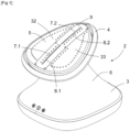
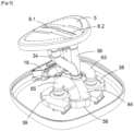
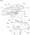
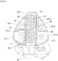
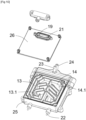
- FIGS. 1 to 12 represent a steaming device 2 configured to steam a garment or linen to be steamed.
- the steaming appliance 2 comprises a base 3 which is intended to rest stably on a horizontal support, and a steaming head 4 which is supported by the base 3 and which comprises a treatment surface 5 on which a garment to be steamed is intended to be placed while the steaming appliance 2 rests on the base 3.
- the steaming apparatus 2 is configured such that steaming of a garment to be steamed is carried out by manually applying the garment to be steamed to the treatment surface 5 and sliding the garment to be steamed over the treatment surface 5, for example in a back and forth movement.
- the base 3 has a substantially square-shaped contour
- the steaming head 4 and the treatment surface 5 each have a substantially triangular-shaped contour.
- a vertex of each of the substantially triangular contours of the steaming head 4 and the treatment surface 5 is oriented towards a rear face of the steaming appliance 2.
- the treatment surface 5 may be substantially flat or curved.
- the steaming head 4 is arranged prominently on the base 3.
- the base 3 comprises a base body 6 on which the steaming head 4 rests, and the base body 6 converges towards the steaming head 4 such that the steaming head 4 projects laterally relative to the base body 6.
- Such a configuration of the steaming head 4 makes it possible to easily slip a shoulder of a shirt to be steamed around the steaming head 4.
- the steaming device 2 may for example have a height of between 20 and 40 cm, and the treatment surface 5 may advantageously be more than 20 cm from the support surface of a horizontal support when the base 3 rests on the horizontal support.
- the steaming head 4 may for example have a maximum width of between 10 and 35 cm, and advantageously of the order of 20 cm, and the base 3 may for example have a maximum width of between 15 and 40 cm, and advantageously of the order of 30 cm.
- the center of gravity of the steaming head 4 and the center of gravity of the base 3 are substantially aligned along a vertical axis when the base 3 rests on a horizontal support.
- the steaming head 4 is inclined towards a front face of the steaming appliance 2, and extends substantially in an extension plane Pe (see figure 3 ) which is inclined at an angle of between 5° and 45° relative to a horizontal plane, and preferably of the order of 20°, when the base 3 rests on a horizontal support.
- the or each normal to the treatment surface 5 is oriented upwards or is inclined at an angle of between 0° and 45° relative to a vertical axis, and preferably of the order of 20°, in the direction of a front face of the steaming appliance 2.
- the treatment surface 5 comprises a first steam emission zone 7.1 having a first steam outlet hole 8.1, and a second steam emission zone 7.2 having a second steam outlet hole 8.2.
- the first steam outlet hole 8.1 is arranged in a front half of the treatment surface 5
- the second steam outlet hole 8.2 is arranged in a rear half of the treatment surface 5.
- the first steam outlet hole 8.1 is a first steam outlet slot
- the second steam outlet hole 8.2 is a second steam outlet slot.
- the first and second steam outlet slots are aligned with each other and extend in the median plane of the treatment surface 5, and also in the median plane of the steaming head 4.
- Each of the first and second steam outlet slots may have a length of between 7 and 15 cm, and for example between 8 and 12 cm, and advantageously of the order of 10 cm.
- the length of each of the first and second steam outlet slots corresponds substantially to the maximum width of a sleeve of a garment to be steamed.
- the treatment surface 5 comprises a heating plate 9 which defines the first and second steam emission zones 7.1, 7.2, and which may for example be metallic.
- the first and second steam outlet holes 8.1, 8.2 are advantageously provided in the heating plate 9.
- the heating plate 9 is arranged in a median portion of the treatment surface 5, and is spaced from a peripheral edge of the steaming head 4.
- the heating plate 9 is centered relative to the median plane P of the treatment surface 5.
- the steaming device 2 is advantageously configured such that, under conditions of use, the treatment surface 5 has a temperature greater than 110°C at the heating plate 9, in order to avoid the formation of condensates on the treatment surface 5.
- the steaming head 4 advantageously comprises a heating element 10 on which the heating plate 9 rests.
- the heating element 10 is more particularly configured to heat the heating plate 9.
- the heating element 10 can advantageously integrate a resistive heating element 10.1.
- the steaming appliance 2 further comprises a first steam distribution circuit 11 which is fluidically connected to the first steam outlet hole 8.1 and which is configured to supply steam to the first steam outlet hole 8.1, and a second steam distribution circuit 12 which is fluidically connected to the second steam outlet hole 8.2 and which is configured to supply steam to the second steam outlet hole 8.2, the second steam distribution circuit 12 being distinct from the first steam distribution circuit 11.
- the steaming appliance 2 also comprises at least one steam generator which is configured to independently supply the first and second steam distribution circuits 11, 12.
- the steaming appliance 2 comprises a first steam generator 13 which is configured to supply steam to the first steam distribution circuit 11 and a second steam generator 14 which is configured to supply steam to the second steam distribution circuit 12.
- the first and second steam generators 13, 14 are arranged in the base 3.
- the first and second steam generators 13, 14 could be arranged in the steaming head 4.
- the steaming appliance 2 further comprises a water tank 15, for example arranged in the base 3, and a supply circuit 16 which is fluidically connected to the water tank 15 and which is configured to supply water to the first and second steam generators 13, 14.
- the supply circuit 16 comprises a supply pump 17 configured to supply the first and second steam generators 13, 14 with water from the water tank 15.
- the first and second steam generators 13, 14 respectively comprise a first instantaneous vaporization chamber 13.1 and a second instantaneous vaporization chamber 14.1 which are each configured to be supplied with water from the water tank 15, and which are respectively configured to supply steam to the first and second steam distribution circuits 11, 12.
- the first and second steam generators 13, 14 are formed by a heating body 18 comprising the first and second instantaneous vaporization chambers 13.1, 14.1.
- the heating body 18 comprises a first water injection opening 19 opening into the first instantaneous vaporization chamber 13.1, and a second water injection opening 21 opening into the second instantaneous vaporization chamber 14.1.
- the first and second water injection openings 19, 21 are connected to the supply circuit 16.
- the heating body 18 further comprises an electric heating resistor 22.
- the heating body 18 also comprises a first steam discharge opening 23 fluidly connected to the first instantaneous vaporization chamber 13.1, and a second steam discharge opening 24 fluidly connected to the second instantaneous vaporization chamber 14.1.
- the heating body 18 comprises a casting 25 in which the electric heating resistor 22 is integrated, and a closing plate 26 which rests on the casting 25.
- the casting 25 and the closing plate 26 delimit the first and second instantaneous vaporization chambers 13.1, 14.1.
- the first steam distribution circuit 11 comprises a first steam flow channel 27 which is delimited by the heating element 10 and the heating plate 9, and a first steam conduit (not visible in the figures), for example flexible and with an internal diameter of the order of 5 mm, which fluidically connects the first flow channel steam 27 to the first instantaneous vaporization chamber 13.1.
- the first steam conduit is more particularly configured to connect the first steam discharge opening 23 to a first steam injection opening 28 provided on the heating element 10 and opening into the first steam flow channel 27.
- the first steam flow channel 27 comprises a first steam flow portion 27.1 comprising a plurality of baffles and a second steam flow portion 27.2 which is substantially rectilinear and which is located opposite the first steam outlet hole 8.1.
- the first steam injection opening 28 opens more particularly into an upstream portion of the first steam flow channel 27.
- the second steam distribution circuit 12 comprises a second steam flow channel 29 which is delimited by the heating element 10 and the heating plate 9, and a second steam conduit (not visible in the figures), for example flexible and with an internal diameter of the order of 5 mm, which fluidically connects the second steam flow channel 29 to the second instantaneous vaporization chamber 14.1.
- the second steam conduit is more particularly configured to connect the second steam discharge opening 24 to a second steam injection opening 31 provided on the heating element 10 and opening into the second steam flow channel 29.
- the second steam flow channel 29 comprises a first steam flow portion 29.1 comprising a plurality of baffles and a second steam flow portion 29.2 which is substantially rectilinear and which is located opposite the second steam outlet hole 8.2.
- the second steam injection opening 31 opens more particularly into an upstream portion of the second steam flow channel 29.
- the treatment surface 5 further comprises at least one suction zone provided with at least one suction orifice.
- the treatment surface 5 comprises a first suction zone 32 and a second suction zone 33 which are arranged on either side of the median plane P of the treatment surface 5, and more precisely on either side of the two steam emission zones 7.1, 7.2, and which are each provided with several suction orifices.
- the steaming apparatus 2 comprises a first suction circuit 34 which is fluidically connected to a first set 35 of suction orifices provided on the treatment surface 5, and a second suction circuit 36 which is distinct from the first suction circuit 34 and which is fluidically connected to a second set 37 of suction orifices provided on the treatment surface 5.
- the suction orifices of the first set 35 of suction orifices are arranged in a front half of the treatment surface 5, and the suction orifices of the second set 37 of suction orifices are arranged in a rear half of the treatment surface 5.
- the separation between the first and second sets 35, 37 is shown diagrammatically in the figure 2 by the separation axis S.
- the steaming appliance 2 also comprises first vacuum means configured to vacuum the first suction circuit 34, and second vacuum means which are distinct from the first vacuum means and which are configured to vacuum the second suction circuit 36.
- first vacuum means comprise a first motor-driven fan 38 which is arranged in the base 3
- second vacuum means comprise a second motor-driven fan 39 which is also arranged in the base 3.
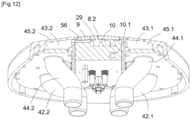
- the first suction circuit 34 comprises a pair of first suction chambers 41.1, 41.2 which are provided in the steaming head 4 and which are arranged on either side of the heating plate 9, and a pair of first suction ducts 42.1, 42.2 which are fluidically connected to the first vacuum means and which open respectively into the first suction chambers 41.1, 41.2
- the second suction circuit 36 comprises a pair second suction chambers 43.1, 43.2 which are provided in the steaming head 4 and which are arranged on either side of the heating plate 9, and a pair of second suction ducts 44.1, 44.2 which are fluidically connected to the second vacuum means and which open respectively into the second suction chambers 43.1, 43.2.
- the first suction chambers 41.1, 41.2 are arranged in a front part of the steaming head 4, and the second suction chambers 43.1, 43.2 are arranged in a rear part of the steaming head 4.
- the treatment surface 5 comprises (see figure 4 ) two side plates 45.1, 45.2, advantageously made of plastic, remaining cold and non-dangerous, which are arranged on either side of the heating plate 9, each of the side plates 45.1, 45.2 partially delimiting one of the first suction chambers 41.1, 41.2 and one of the second suction chambers 43.1, 43.2.
- the first and second suction circuits 34, 36 respectively comprise a first exhaust outlet 46 and a second exhaust outlet 47 which are arranged on a rear face of the steaming appliance 2, and more particularly on a rear face of the base body 6.
- the first set 35 of suction ports comprises a first subset 48 of suction ports and a second subset 49 of suction ports which are arranged on either side of the first steam emission zone 7.1, and more precisely on either side of the heating plate 9
- the second set 37 of suction ports comprises a third subset 51 of suction ports and a fourth subset 52 of suction ports which are arranged on either side of the second steam emission zone 7.2, and more precisely on either side of the heating plate 9.
- the suction ports of the first subset 48 and of the third subset 51 are formed in the side plate 45.1
- the suction ports of the second subset 49 and of the fourth subset 52 are provided in the side plate 45.2.
- suction ports of the first subassembly 48 open into the first suction chamber 41.1 and the suction ports of the second subassembly 49 open into the first suction chamber 41.2, while the suction ports of the third subassembly 51 open into the second suction chamber 43.1, and the suction ports of the fourth subassembly 52 open into the second suction chamber 43.2.
- the second subassembly 49 comprises a plurality of suction ports located near and along the heating plate 9, and advantageously along a first lateral edge 9.1 of the heating plate 9, and the third subassembly 51 comprises a plurality of suction ports located near and along the heating plate 9, and advantageously along a second lateral edge 9.2 of the heating plate 9.
- the first set 35 further comprises a first series 53 of suction ports provided in the heating plate 9 in the vicinity of and along the first steam outlet hole 8.1
- the second set 37 of suction ports comprises a second series 54 of suction ports provided in the heating plate 9 in the vicinity of and along the second steam outlet hole 8.2.
- the suction ports of the first series 53 are substantially aligned
- the suction ports of the second series 54 are also substantially aligned.
- the first and second series 53, 54 are arranged on either side of the median plane P of the treatment surface 5.
- the distance between the first steam outlet hole 8.1 and each suction port of the first series 53 is advantageously less than 1 cm and for example of the order of 3 mm, and the distance between the second steam outlet hole 8.2 and each suction port of the second series 54 is also advantageously less than 1 cm and for example of the order of 3 mm.
- the suction ports of the first series 53 are fluidically connected to the first suction chamber 41.1, while the suction ports of the second series 54 are fluidically connected to the second suction chamber 43.2.
- the first suction circuit 34 comprises a plurality of first connecting channels 55 provided on the heating element 10 and each configured to fluidically connect a respective suction port of the first series 53 with the first suction chamber 41.1, and a plurality of second connecting channels 56 provided on the heating element 10 and each configured to fluidically connect a respective suction port of the second series 54 with the second suction chamber 43.2.
- the sum of the passage sections of all the suction orifices provided on the treatment surface 5 corresponds substantially to the sum of the passage sections of the first and second suction ducts 42.1, 42.2, 44.1, 44.2, and substantially to the sum of the passage sections of the first and second suction chambers 41.1, 41.2, 43.1, 43.2.
- the first suction circuit 34 further comprises a first condensate recovery device 57 configured to recover condensates formed in the first suction circuit 34, and for example in the first suction ducts 42.1, 42.2 and/or the first suction chambers 41.1, 41.2
- the second suction circuit 36 further comprises a second condensate recovery device 58 configured to recover condensates formed in the second suction circuit 36, and for example in the second suction ducts 44.1, 44.2 and/or the second suction chambers 43.1, 43.2.
- each of the first and second condensate recovery devices 57, 58 is configured to reinject the recovered condensates into the water tank 15 configured to supply water to the first and second steam generators 13, 14.
- the first condensate recovery device 57 comprises a first condensate recovery chamber 59 provided with a first condensate discharge opening 61 opening into the water tank 15, and the second condensate recovery device 57 comprises a second condensate recovery chamber 59 provided with a second condensate discharge opening 61 opening into the water tank 15, and the second condensate recovery device 57 comprises a second condensate recovery chamber 59 provided with a second condensate discharge opening 61 opening into the water tank 15.
- condensate recovery 58 comprises a second condensate recovery chamber (not visible in the figures) provided with a second condensate discharge opening (not visible in the figures) opening into the water tank 15.
- the first and/or second condensate recovery devices may advantageously comprise a filter, preferably removable, to prevent the hole from becoming clogged and the water in the tank from becoming soiled by tissue fibrils.
- the first suction circuit 34 comprises a first connecting conduit 62 connecting the first suction conduits 42.1, 42.2 to the first condensate recovery chamber 59, and a second connecting conduit 63 connecting the first condensate recovery chamber 59 to the first vacuum means
- the second suction circuit 36 comprises a third connecting conduit 64 connecting the second suction conduits 44.1, 44.2 to the second condensate recovery chamber, and a fourth connecting conduit 65 connecting the second condensate recovery chamber to the second vacuum means.
- the steaming appliance 2 further comprises a control unit 66 which is configured in particular to control the operation of the first and second steam generators 13, 14, the first and second motor fans 38, 39, the heating element 10 and the feed pump 17.
- the control of the operation of the first and second motor fans 38, 39 could be carried out by pressing a suction control button provided on the base 3.
- the treatment surface 5 could comprise one or more presence sensors configured to automatically detect the presence of a garment to be steamed on the treatment surface 5, and the control unit 66 could be configured to control the operation of the first and second steam generators 13, 14 and the first and second motor-driven fans 38, 39 as a function of the detection of the presence of a garment on the treatment surface 5.
- the steaming appliance 2 could include user presence detection, for example for an eco-energy mode, to activate the steam and the suction only in the presence of the user.
- the latter could comprise a steam control pedal intended to be actuated by the foot of a user when the latter wishes to spray steam through the first and second steam outlet holes 8.1, 8.2.
- first and second steam generators 13, 14 could be formed by two heating bodies distinct from each other.
Landscapes
- Engineering & Computer Science (AREA)
- Textile Engineering (AREA)
- Treatment Of Fiber Materials (AREA)
- Irons (AREA)
- Cookers (AREA)
Claims (15)
- Glättungseinrichtung (2), umfassend einen Sockel (3), der dazu bestimmt ist, stabil auf einem horizontalen Träger zu ruhen, und einen von dem Sockel (3) getragenen Glättungskopf (4), wobei der Glättungskopf (4) eine Behandlungsoberfläche (5) umfasst, auf der ein zu glättendes Kleidungsstück bestimmt ist, angeordnet zu werden, wobei die Behandlungsoberfläche (5) mindestens einen Dampfemissionsbereich umfasst, wobei die Glättungseinrichtung (2) derart konfiguriert ist, dass eine Glättung eines zu glättenden Kleidungsstücks durchgeführt wird, indem das zu glättende Kleidungsstück von Hand auf die Behandlungsoberfläche (5) aufgebracht wird, während die Glättungseinrichtung (2) auf dem Sockel (3) ruht, und indem das zu glättende Kleidungsstück auf der Behandlungsoberfläche (5) geschoben wird, dadurch gekennzeichnet, dass die Glättungseinrichtung einen ersten Dampfverteilungskreislauf (11), einen zweiten Dampfverteilungskreislauf (12), der sich vom ersten Dampfverteilungskreislauf (11 ) unterscheidet, und mindestens einen Dampferzeuger umfasst, der konfiguriert ist, um den ersten und den zweiten Dampfverteilungskreislauf (11, 12) unabhängig zu versorgen, wobei der mindestens eine Dampfemissionsbereich mindestens eine erste Dampfaustrittsöffnung (8.1), die strömungstechnisch mit dem ersten Dampfverteilungskreislauf (11) verbunden ist, und mindestens eine zweite Dampfaustrittsöffnung (8.2), die strömungstechnisch mit dem zweiten Dampfverteilungskreislauf (12) verbunden ist, umfasst.
- Glättungseinrichtung (2) nach Anspruch 1, die einen ersten Dampferzeuger (13) umfasst, der konfiguriert ist, um den ersten Dampfverteilungskreislauf (11) mit Dampf zu versorgen, und einen zweiten Dampferzeuger (14), der konfiguriert ist, um den zweiten Dampfverteilungskreislauf (12) mit Dampf zu versorgen.
- Glättungseinrichtung (2) nach einem der Ansprüche 1 bis 2, wobei die Behandlungsoberfläche (5) eine Heizplatte (9) umfasst, die zumindest teilweise den mindestens einen Dampfemissionsbereich definiert, wobei die erste und die zweite Dampfaustrittsöffnung in der Heizplatte (9) eingerichtet sind.
- Glättungseinrichtung (2) nach Anspruch 3, wobei die Heizplatte (9) in einem mittleren Teil der Behandlungsoberfläche (5) angeordnet ist.
- Glättungseinrichtung (2) nach Anspruch 3 oder 4 in Kombination mit Anspruch 2, wobei der Glättungskopf (4) ein Heizelement (10) umfasst, auf dem die Heizplatte (9) ruht, wobei der erste Dampfverteilungskreislauf (11) einen ersten Dampfablasskanal (27) umfasst, der von dem Heizelement (10) und der Heizplatte (9) begrenzt ist und der strömungstechnisch mit dem ersten Dampferzeuger (13) verbunden ist, wobei der zweite Dampfverteilungskreislauf (12) einen zweiten Dampfablasskanal (29) umfasst, der von dem Heizelement (10) und der Heizplatte (9) begrenzt ist und der strömungstechnisch mit dem zweiten Dampferzeuger (14) verbunden ist.
- Glättungseinrichtung (2) nach einem der Ansprüche 1 bis 5, wobei die Behandlungsoberfläche (5) weiter mindestens einen Aspirationsbereich (32, 33) umfasst, der mit mehreren Aspirationsöffnungen versehen ist.
- Glättungseinrichtung (2) nach Anspruch 6, die einen ersten Aspirationskreislauf (34) und einen zweiten Aspirationskreislauf (36), der sich von dem ersten Aspirationskreislauf unterscheidet, umfasst, wobei die Aspirationsöffnungen mindestens eine Aspirationsöffnung, die fluidisch mit dem ersten Aspirationskreislauf (34) verbunden ist, und mindestens eine Aspirationsöffnung umfassen, die fluidisch mit dem zweiten Aspirationskreislauf (36) verbunden ist.
- Glättungseinrichtung (2) nach Anspruch 7, wobei die Aspirationsöffnungen eine erste Anordnung (35) von Aspirationsöffnungen, die fluidisch mit dem ersten Aspirationskreislauf (34) verbunden sind, und eine zweite Anordnung (37) von Aspirationsöffnungen umfassen, die fluidisch mit dem zweiten Aspirationskreislauf (36) verbunden sind.
- Glättungseinrichtung (2) nach einem der Ansprüche 1 bis 8, wobei der Glättungskopf (4) auf vorspringende Weise auf dem Sockel (3) angeordnet ist.
- Glättungseinrichtung (2) nach einem der Ansprüche 1 bis 9, wobei der Sockel (3) einen Sockelkörper (6) umfasst, auf dem der Glättungskopf (4) ruht, wobei der Sockelkörper (6) in Richtung des Glättungskopfes (4) konvergiert und der Glättungskopf (4) in Bezug auf den Sockelkörper (6) seitlich hervorsteht.
- Glättungseinrichtung (2) nach einem der Ansprüche 1 bis 10, wobei der Schwerpunkt des Glättungskopfes (4) und der Schwerpunkt des Sockels (3) im Wesentlichen entlang einer vertikalen Achse ausgerichtet sind, wenn der Sockel (3) auf einem horizontalen Träger ruht.
- Glättungseinrichtung (2) nach einem der Ansprüche 1 bis 11, wobei, wenn der Sockel (3) auf einer horizontalen Stütze ruht, die oder jede Behandlungsoberfläche (5) nach oben gerichtet ist oder in einem Winkel zwischen 0° und 45° in Bezug auf eine vertikale Achse in Richtung einer Vorderseite der Glättungseinrichtung (2) geneigt ist.
- Glättungseinrichtung (2) nach einem der Ansprüche 1 bis 12, wobei der Sockel (3) Griffe umfasst, die sich in der Nähe einer unteren Behandlungsoberfläche des Sockels (3) befinden.
- Glättungseinrichtung (2) nach einem der Ansprüche 1 bis 13, wobei die Glättungseinrichtung mindestens eine Kondensate-Rückgewinnungsvorrichtung (57, 58) umfasst.
- Verfahren zur Glättung eines Kleidungsstücks mithilfe der Einrichtung nach einem der vorstehenden Ansprüche, dadurch gekennzeichnet, dass die Glättung des Kleidungsstücks durchgeführt wird, indem das zu glättende Kleidungsstück von Hand auf die Behandlungsoberfläche (5) aufgebracht wird, während die Glättungseinrichtung (2) stabil auf dem Sockel (3) ruht und indem das zu glättende Kleidungsstück auf der Behandlungsoberfläche (5) geschoben wird.
Applications Claiming Priority (2)
| Application Number | Priority Date | Filing Date | Title |
|---|---|---|---|
| FR2002715A FR3108340B1 (fr) | 2020-03-19 | 2020-03-19 | Appareil de défroissage à vapeur muni de deux circuits de distribution de vapeur indépendants |
| PCT/EP2021/055225 WO2021185572A1 (fr) | 2020-03-19 | 2021-03-02 | Appareil de defroissage a vapeur muni de deux circuits de distribution de vapeur independants |
Publications (3)
| Publication Number | Publication Date |
|---|---|
| EP4121592A1 EP4121592A1 (de) | 2023-01-25 |
| EP4121592B1 true EP4121592B1 (de) | 2024-12-04 |
| EP4121592C0 EP4121592C0 (de) | 2024-12-04 |
Family
ID=70457032
Family Applications (1)
| Application Number | Title | Priority Date | Filing Date |
|---|---|---|---|
| EP21708033.2A Active EP4121592B1 (de) | 2020-03-19 | 2021-03-02 | Glättungsgerät mit zwei unabhängigen dampfverteilungskreisen |
Country Status (4)
| Country | Link |
|---|---|
| EP (1) | EP4121592B1 (de) |
| CN (1) | CN115298387B (de) |
| FR (1) | FR3108340B1 (de) |
| WO (1) | WO2021185572A1 (de) |
Families Citing this family (3)
| Publication number | Priority date | Publication date | Assignee | Title |
|---|---|---|---|---|
| FR3137396B1 (fr) * | 2022-07-04 | 2024-07-19 | Seb Sa | Appareil de défroissage |
| FR3137397B1 (fr) * | 2022-07-04 | 2024-07-19 | Seb Sa | Appareil de défroissage |
| USD1079159S1 (en) * | 2024-01-06 | 2025-06-10 | Grobel (Shenzhen) Information Technology Co., Ltd. | Steam iron |
Family Cites Families (9)
| Publication number | Priority date | Publication date | Assignee | Title |
|---|---|---|---|---|
| US4496826A (en) * | 1983-02-14 | 1985-01-29 | Leonard Osrow | Hand-held shock-resistant electrolytically heated steam producing apparatus |
| CA2279702C (en) | 1999-08-05 | 2004-10-12 | James Yoshiki Imada | Garment steamer |
| KR200448256Y1 (ko) * | 2008-01-30 | 2010-03-25 | 챙 삼손 | 스팀 다리미 |
| EP2455540A1 (de) * | 2010-11-18 | 2012-05-23 | Koninklijke Philips Electronics N.V. | Dampfkopf für einen Kleidungsdampfer |
| CN201883321U (zh) * | 2010-11-26 | 2011-06-29 | 漳州灿坤实业有限公司 | 一种挂烫机蒸汽喷头 |
| CN106480693B (zh) * | 2016-11-21 | 2018-10-02 | 宁波凯波集团有限公司 | 一种超大蒸汽量的蒸汽发生器及多功能蒸汽刷 |
| FR3060027B1 (fr) * | 2016-12-13 | 2018-11-23 | Seb S.A. | Appareil de defroissage a la vapeur |
| CN106835657B (zh) * | 2016-12-20 | 2019-01-29 | 广州视源电子科技股份有限公司 | 一种熨烫方法及熨烫装置 |
| FR3072100B1 (fr) * | 2017-10-05 | 2020-07-31 | Seb Sa | Appareil de defroissage equipe d'une chambre de vaporisation munie d'un orifice de nettoyage |
-
2020
- 2020-03-19 FR FR2002715A patent/FR3108340B1/fr active Active
-
2021
- 2021-03-02 WO PCT/EP2021/055225 patent/WO2021185572A1/fr not_active Ceased
- 2021-03-02 EP EP21708033.2A patent/EP4121592B1/de active Active
- 2021-03-02 CN CN202180021793.3A patent/CN115298387B/zh active Active
Also Published As
| Publication number | Publication date |
|---|---|
| EP4121592A1 (de) | 2023-01-25 |
| FR3108340B1 (fr) | 2022-04-29 |
| WO2021185572A1 (fr) | 2021-09-23 |
| CN115298387A (zh) | 2022-11-04 |
| EP4121592C0 (de) | 2024-12-04 |
| CN115298387B (zh) | 2025-05-06 |
| FR3108340A1 (fr) | 2021-09-24 |
Similar Documents
| Publication | Publication Date | Title |
|---|---|---|
| CA3252477A1 (fr) | Appareil de défroissage | |
| FR3137395A1 (fr) | Appareil de défroissage | |
| EP4121592A1 (de) | Dampfglättungsvorrichtung mit zwei unabhängigen dampfverteilungskreisläufen | |
| CA2835785C (fr) | Appareil de repassage a la vapeur comportant un generateur de vapeur sous pression et un fer a repasser | |
| EP3868951B1 (de) | Tragbares dampfentknitterungsgerät | |
| EP3365490B1 (de) | Dampfglättvorrichtung mit einem über eine leitung mit einem glättkopf verbundene basiseinheit | |
| FR3072099B1 (fr) | Tete de defroissage comprenant une chambre interne pourvue de canaux d'expulsion de vapeur | |
| EP4121590B1 (de) | Dampfgleitgerät mit mindestens einem sauganschluss | |
| EP4121591B1 (de) | Glättungsgerät mit einem geneigten glättungskopf | |
| FR3072101B1 (fr) | Tete de defroissage comprenant une chambre interne pourvue de canaux d'expulsion de vapeur | |
| EP4367314B1 (de) | Gerät zur behandlung von wäsche mit dampf mit einer basis, die dazu bestimmt ist, auf einer unterlage zu ruhen | |
| WO2026012724A1 (fr) | Appareil de défroissage | |
| WO2026012725A1 (fr) | Appareil de défroissage | |
| EP4551751A1 (de) | Knitterglättungsvorrichtung | |
| WO2026012720A1 (fr) | Appareil de défroissage | |
| WO2026012721A1 (fr) | Appareil de défroissage | |
| WO2026012723A1 (fr) | Appareil de défroissage | |
| EP4678809A1 (de) | Dampfgerät | |
| EP4551748A1 (de) | Glättungsvorrichtung zur faltenentfernung | |
| FR3164486A1 (fr) | Appareil de défroissage | |
| FR3042798A1 (fr) | Appareil de defroissage a la vapeur comprenant une base reliee a une tete de defroissage par un conduit |
Legal Events
| Date | Code | Title | Description |
|---|---|---|---|
| STAA | Information on the status of an ep patent application or granted ep patent |
Free format text: STATUS: UNKNOWN |
|
| STAA | Information on the status of an ep patent application or granted ep patent |
Free format text: STATUS: THE INTERNATIONAL PUBLICATION HAS BEEN MADE |
|
| PUAI | Public reference made under article 153(3) epc to a published international application that has entered the european phase |
Free format text: ORIGINAL CODE: 0009012 |
|
| STAA | Information on the status of an ep patent application or granted ep patent |
Free format text: STATUS: REQUEST FOR EXAMINATION WAS MADE |
|
| 17P | Request for examination filed |
Effective date: 20221017 |
|
| AK | Designated contracting states |
Kind code of ref document: A1 Designated state(s): AL AT BE BG CH CY CZ DE DK EE ES FI FR GB GR HR HU IE IS IT LI LT LU LV MC MK MT NL NO PL PT RO RS SE SI SK SM TR |
|
| DAV | Request for validation of the european patent (deleted) | ||
| DAX | Request for extension of the european patent (deleted) | ||
| GRAP | Despatch of communication of intention to grant a patent |
Free format text: ORIGINAL CODE: EPIDOSNIGR1 |
|
| STAA | Information on the status of an ep patent application or granted ep patent |
Free format text: STATUS: GRANT OF PATENT IS INTENDED |
|
| INTG | Intention to grant announced |
Effective date: 20240711 |
|
| RIN1 | Information on inventor provided before grant (corrected) |
Inventor name: GELUS, DOMINIQUE |
|
| GRAS | Grant fee paid |
Free format text: ORIGINAL CODE: EPIDOSNIGR3 |
|
| GRAA | (expected) grant |
Free format text: ORIGINAL CODE: 0009210 |
|
| STAA | Information on the status of an ep patent application or granted ep patent |
Free format text: STATUS: THE PATENT HAS BEEN GRANTED |
|
| AK | Designated contracting states |
Kind code of ref document: B1 Designated state(s): AL AT BE BG CH CY CZ DE DK EE ES FI FR GB GR HR HU IE IS IT LI LT LU LV MC MK MT NL NO PL PT RO RS SE SI SK SM TR |
|
| REG | Reference to a national code |
Ref country code: CH Ref legal event code: EP |
|
| REG | Reference to a national code |
Ref country code: DE Ref legal event code: R096 Ref document number: 602021022828 Country of ref document: DE |
|
| REG | Reference to a national code |
Ref country code: IE Ref legal event code: FG4D Free format text: LANGUAGE OF EP DOCUMENT: FRENCH |
|
| U01 | Request for unitary effect filed |
Effective date: 20241205 |
|
| U07 | Unitary effect registered |
Designated state(s): AT BE BG DE DK EE FI FR IT LT LU LV MT NL PT RO SE SI Effective date: 20241216 |
|
| U20 | Renewal fee for the european patent with unitary effect paid |
Year of fee payment: 5 Effective date: 20250225 |
|
| PG25 | Lapsed in a contracting state [announced via postgrant information from national office to epo] |
Ref country code: HR Free format text: LAPSE BECAUSE OF FAILURE TO SUBMIT A TRANSLATION OF THE DESCRIPTION OR TO PAY THE FEE WITHIN THE PRESCRIBED TIME-LIMIT Effective date: 20241204 |
|
| PG25 | Lapsed in a contracting state [announced via postgrant information from national office to epo] |
Ref country code: ES Free format text: LAPSE BECAUSE OF FAILURE TO SUBMIT A TRANSLATION OF THE DESCRIPTION OR TO PAY THE FEE WITHIN THE PRESCRIBED TIME-LIMIT Effective date: 20241204 |
|
| PG25 | Lapsed in a contracting state [announced via postgrant information from national office to epo] |
Ref country code: NO Free format text: LAPSE BECAUSE OF FAILURE TO SUBMIT A TRANSLATION OF THE DESCRIPTION OR TO PAY THE FEE WITHIN THE PRESCRIBED TIME-LIMIT Effective date: 20250304 |
|
| PG25 | Lapsed in a contracting state [announced via postgrant information from national office to epo] |
Ref country code: GR Free format text: LAPSE BECAUSE OF FAILURE TO SUBMIT A TRANSLATION OF THE DESCRIPTION OR TO PAY THE FEE WITHIN THE PRESCRIBED TIME-LIMIT Effective date: 20250305 |
|
| PG25 | Lapsed in a contracting state [announced via postgrant information from national office to epo] |
Ref country code: RS Free format text: LAPSE BECAUSE OF FAILURE TO SUBMIT A TRANSLATION OF THE DESCRIPTION OR TO PAY THE FEE WITHIN THE PRESCRIBED TIME-LIMIT Effective date: 20250304 |
|
| PG25 | Lapsed in a contracting state [announced via postgrant information from national office to epo] |
Ref country code: SM Free format text: LAPSE BECAUSE OF FAILURE TO SUBMIT A TRANSLATION OF THE DESCRIPTION OR TO PAY THE FEE WITHIN THE PRESCRIBED TIME-LIMIT Effective date: 20241204 |
|
| PG25 | Lapsed in a contracting state [announced via postgrant information from national office to epo] |
Ref country code: PL Free format text: LAPSE BECAUSE OF FAILURE TO SUBMIT A TRANSLATION OF THE DESCRIPTION OR TO PAY THE FEE WITHIN THE PRESCRIBED TIME-LIMIT Effective date: 20241204 |
|
| PG25 | Lapsed in a contracting state [announced via postgrant information from national office to epo] |
Ref country code: IS Free format text: LAPSE BECAUSE OF FAILURE TO SUBMIT A TRANSLATION OF THE DESCRIPTION OR TO PAY THE FEE WITHIN THE PRESCRIBED TIME-LIMIT Effective date: 20250404 |
|
| PG25 | Lapsed in a contracting state [announced via postgrant information from national office to epo] |
Ref country code: SK Free format text: LAPSE BECAUSE OF FAILURE TO SUBMIT A TRANSLATION OF THE DESCRIPTION OR TO PAY THE FEE WITHIN THE PRESCRIBED TIME-LIMIT Effective date: 20241204 |
|
| PG25 | Lapsed in a contracting state [announced via postgrant information from national office to epo] |
Ref country code: CZ Free format text: LAPSE BECAUSE OF FAILURE TO SUBMIT A TRANSLATION OF THE DESCRIPTION OR TO PAY THE FEE WITHIN THE PRESCRIBED TIME-LIMIT Effective date: 20241204 |
|
| PLBE | No opposition filed within time limit |
Free format text: ORIGINAL CODE: 0009261 |
|
| STAA | Information on the status of an ep patent application or granted ep patent |
Free format text: STATUS: NO OPPOSITION FILED WITHIN TIME LIMIT |
|
| PG25 | Lapsed in a contracting state [announced via postgrant information from national office to epo] |
Ref country code: MC Free format text: LAPSE BECAUSE OF FAILURE TO SUBMIT A TRANSLATION OF THE DESCRIPTION OR TO PAY THE FEE WITHIN THE PRESCRIBED TIME-LIMIT Effective date: 20241204 |
|
| REG | Reference to a national code |
Ref country code: CH Ref legal event code: L10 Free format text: ST27 STATUS EVENT CODE: U-0-0-L10-L00 (AS PROVIDED BY THE NATIONAL OFFICE) Effective date: 20251015 |
|
| REG | Reference to a national code |
Ref country code: CH Ref legal event code: H13 Free format text: ST27 STATUS EVENT CODE: U-0-0-H10-H13 (AS PROVIDED BY THE NATIONAL OFFICE) Effective date: 20251023 |
|
| 26N | No opposition filed |
Effective date: 20250905 |
|
| GBPC | Gb: european patent ceased through non-payment of renewal fee |
Effective date: 20250304 |
|
| PG25 | Lapsed in a contracting state [announced via postgrant information from national office to epo] |
Ref country code: GB Free format text: LAPSE BECAUSE OF NON-PAYMENT OF DUE FEES Effective date: 20250304 |
|
| PG25 | Lapsed in a contracting state [announced via postgrant information from national office to epo] |
Ref country code: CH Free format text: LAPSE BECAUSE OF NON-PAYMENT OF DUE FEES Effective date: 20250331 |
|
| PG25 | Lapsed in a contracting state [announced via postgrant information from national office to epo] |
Ref country code: IE Free format text: LAPSE BECAUSE OF NON-PAYMENT OF DUE FEES Effective date: 20250302 |
|
| U20 | Renewal fee for the european patent with unitary effect paid |
Year of fee payment: 6 Effective date: 20260226 |