EP4366152A1 - Power conversion device - Google Patents
Power conversion device Download PDFInfo
- Publication number
- EP4366152A1 EP4366152A1 EP21948484.7A EP21948484A EP4366152A1 EP 4366152 A1 EP4366152 A1 EP 4366152A1 EP 21948484 A EP21948484 A EP 21948484A EP 4366152 A1 EP4366152 A1 EP 4366152A1
- Authority
- EP
- European Patent Office
- Prior art keywords
- axis
- gain
- power converter
- flux component
- value
- Prior art date
- Legal status (The legal status is an assumption and is not a legal conclusion. Google has not performed a legal analysis and makes no representation as to the accuracy of the status listed.)
- Withdrawn
Links
Images



Classifications
-
- H—ELECTRICITY
- H02—GENERATION; CONVERSION OR DISTRIBUTION OF ELECTRIC POWER
- H02P—CONTROL OR REGULATION OF ELECTRIC MOTORS, ELECTRIC GENERATORS OR DYNAMO-ELECTRIC CONVERTERS; CONTROLLING TRANSFORMERS, REACTORS OR CHOKE COILS
- H02P21/00—Arrangements or methods for the control of electric machines by vector control, e.g. by control of field orientation
- H02P21/24—Vector control not involving the use of rotor position or rotor speed sensors
- H02P21/26—Rotor flux based control
-
- H—ELECTRICITY
- H02—GENERATION; CONVERSION OR DISTRIBUTION OF ELECTRIC POWER
- H02P—CONTROL OR REGULATION OF ELECTRIC MOTORS, ELECTRIC GENERATORS OR DYNAMO-ELECTRIC CONVERTERS; CONTROLLING TRANSFORMERS, REACTORS OR CHOKE COILS
- H02P21/00—Arrangements or methods for the control of electric machines by vector control, e.g. by control of field orientation
- H02P21/0003—Control strategies in general, e.g. linear type, e.g. P, PI, PID, using robust control
- H02P21/0014—Control strategies in general, e.g. linear type, e.g. P, PI, PID, using robust control using neural networks
-
- H—ELECTRICITY
- H02—GENERATION; CONVERSION OR DISTRIBUTION OF ELECTRIC POWER
- H02P—CONTROL OR REGULATION OF ELECTRIC MOTORS, ELECTRIC GENERATORS OR DYNAMO-ELECTRIC CONVERTERS; CONTROLLING TRANSFORMERS, REACTORS OR CHOKE COILS
- H02P21/00—Arrangements or methods for the control of electric machines by vector control, e.g. by control of field orientation
- H02P21/05—Arrangements or methods for the control of electric machines by vector control, e.g. by control of field orientation specially adapted for damping motor oscillations, e.g. for reducing hunting
-
- H—ELECTRICITY
- H02—GENERATION; CONVERSION OR DISTRIBUTION OF ELECTRIC POWER
- H02P—CONTROL OR REGULATION OF ELECTRIC MOTORS, ELECTRIC GENERATORS OR DYNAMO-ELECTRIC CONVERTERS; CONTROLLING TRANSFORMERS, REACTORS OR CHOKE COILS
- H02P21/00—Arrangements or methods for the control of electric machines by vector control, e.g. by control of field orientation
- H02P21/14—Estimation or adaptation of machine parameters, e.g. flux, current or voltage
- H02P21/141—Flux estimation
-
- H—ELECTRICITY
- H02—GENERATION; CONVERSION OR DISTRIBUTION OF ELECTRIC POWER
- H02P—CONTROL OR REGULATION OF ELECTRIC MOTORS, ELECTRIC GENERATORS OR DYNAMO-ELECTRIC CONVERTERS; CONTROLLING TRANSFORMERS, REACTORS OR CHOKE COILS
- H02P21/00—Arrangements or methods for the control of electric machines by vector control, e.g. by control of field orientation
- H02P21/14—Estimation or adaptation of machine parameters, e.g. flux, current or voltage
- H02P21/18—Estimation of position or speed
-
- H—ELECTRICITY
- H02—GENERATION; CONVERSION OR DISTRIBUTION OF ELECTRIC POWER
- H02P—CONTROL OR REGULATION OF ELECTRIC MOTORS, ELECTRIC GENERATORS OR DYNAMO-ELECTRIC CONVERTERS; CONTROLLING TRANSFORMERS, REACTORS OR CHOKE COILS
- H02P21/00—Arrangements or methods for the control of electric machines by vector control, e.g. by control of field orientation
- H02P21/22—Current control, e.g. using a current control loop
Definitions
- This invention relates to a power converter apparatus.
- the controller's memory stores magnet motor induced voltage data, and based on the angular frequency ⁇ and rotation position ⁇ , d-axis and q-axis induced voltage command values are generated based on the angular frequency ⁇ and rotational position ⁇ , and the control technique to make the current sinusoidal is described in Patent Document 1.
- Patent Document 1 it is necessary to store magnet motor induced voltage data in the controller's memory.
- the induced voltage is a square wave
- current pulsation due to odd components (11th, 13th, 17th, 19th, 23rd, 25th%) excluding multiples of 3 of the harmonic components may occur.
- the generation of current pulsation is possible.
- the purpose of this invention is to provide a power converter apparatus that makes the magnet motor current sinusoidal without having induced voltage data.
- One preferred example of the invention is a power converter apparatus comprising a power converter that outputs signal to the magnet motor to vary the output frequency, output voltage and output current of the magnet motor, a control unit controls the power converter, wherein the control unit calculating the gain of the magnetic flux component of the q-axis, which varies with the phase of the magnet motor, calculating the d-axis induced voltage command value based on a value of the induced voltage coefficient, frequency estimates or frequency command value, and the gain of the flux component of the q-axis.
- the current of magnet motor can be sinusoidal without having induced voltage data.
- Fig. 1 shows a system configuration diagram with power converter apparatus and magnet motor in Example 1.
- Magnet motor 1 outputs motor torque that is a composite of the torque component due to the magnetic flux of the permanent magnet and the torque component due to the inductance of the armature winding.
- Power converter 2 is equipped with semiconductor devices as switching elements. Power converter 2 inputs 3-phase AC voltage command value v u *, v v *, v w * and outputs voltage values proportional to 3-phase AC voltage command value v u *, v v *, v w * based on the output of power converter 2, magnet motor 1 is driven, and the output voltage value, output frequency value, and output current value of magnet motor! are controlled variably.
- IGBT Insulated gate bipolar transistor
- DC power supply 3 supplies DC voltage and DC current to power converter2.
- the current detector 4 outputs i uc , i vc , and i wc , which are the detected values of the alternating current i u , i v , and i w of the three phase magnet motor 1.
- the current detector 4 detects the alternating current of two of the three phase magnet motor 1, for example, phase u and phase w.
- the current detector 4 is shown in the power converter apparatus, but it can also be located outside the power converter apparatus.
- the control unit is equipped with a coordinate conversion unit 5, speed control arithmetic unit 6, magnetic flux gain calculation unit 7, vector control arithmetic unit 8, phase error estimation unit 9, frequency and phase estimation 10, and coordinate conversion unit 11 described below.
- Unit 8 phase error estimation unit 9, frequency and phase estimation 10, and coordinate conversion unit 11.
- the control unit controls the output of power converter2 so that the output voltage value, output frequency value, and output current of magnet motor1 are controlled variably.
- the control unit is composed of microcomputers and semiconductor integrated circuits (arithmetic and control means) such as DSP (digital signal processor), etc. Any or all of the control unit can be composed of hardware such as ASIC (Application Specific Integrated Circuit) and FPGA (Field Programmable Gate Array).
- DSP digital signal processor
- Any or all of the control unit can be composed of hardware such as ASIC (Application Specific Integrated Circuit) and FPGA (Field Programmable Gate Array).
- the CPU (Central Processing Unit) of the control unit reads the program stored in the memory or other recording device and executes the processing of each part of the coordinate conversion unit5 and other parts described above.
- Coordinate conversion unit 5 outputs current sense values i dc and i qc for the d- and q-axes from the three-phase alternating current i u , i v , i w detection values i uc , i vc , i wc and phase estimate value ⁇ dc .
- the speed control arithmetic unit 6 calculates the torque command value ⁇ * based on the frequency command value ⁇ r * and frequency estimates ⁇ dc and divides it by the torque coefficient to output the q-axis current command value i q *
- the magnetic flux gain calculation unit 7 outputs the gains G d (q dc ) and G q (q dc ) of the d-axis and q-axis magnetic flux components that vary with phase based on the phase estimate value ⁇ dc
- the vector control arithmetic unit 8 outputs current command value i d *, i q *, current sense value i dc , i qc , frequency estimates ⁇ dc of the d-axis and q-axis, the electrical circuit parameters of magnet motor 1 and voltage command value v dc ** and v qc ** are calculated based on the gains G d (q dc ) and G q (q dc ) of the magnetic flux components of the q-axis and d-axis.
- the phase error estimation unit 9 outputs the estimated phase error ⁇ c ,which is the deviation between the phase estimate value ⁇ dc ,which is the phase of the control, and the phase ⁇ d of the magnet motor1 by using the control axis d-axis and q-axis voltage command value v dc **, v qc **, frequency estimates ⁇ dc , current sense value i dc , i qc and electrical circuit parameters of magnet motor 1.
- the frequency and phase estimation 10 outputs the frequency estimate ⁇ dc and phase estimate value ⁇ dc based on the phase error estimates ⁇ c
- Coordinate conversion unit 11 outputs 3-phase AC voltage command value v u *, v v *, and v w * from d-axis and q-axis voltage command value v dc ** and v qc ** and phase estimate value ⁇ dc .
- the speed control arithmetic unit 6 calculates the torque command ⁇ * and the current command value i q * of the q-axis according to Formula 1 by proportional and integral control so that the frequency estimates ⁇ dc follow the frequency command value ⁇ r *.
- Figure 2 shows the block diagram of the magnetic flux gain calculation unit 7, which consists of the q-axis magnetic flux gain calculation unit 71 and the d-axis magnetic flux gain calculation unit 72. flux gain calculation unit 72 for the d-axis.
- the q-axis magnetic flux gain calculation unit 71 calculates the sine function of the phase estimate according to Formula 2 using the phase estimate value ⁇ dc and outputs the q-axis magnetic flux gain G q ( ⁇ dc ).
- the magnetic flux gain calculation unit 72 of d-axis calculates the sine function of the phase estimate according to Formula 3 using the phase estimate value ⁇ dc and outputs the magnetic flux gain G q ( ⁇ dc ) of d-axis.
- N is the order and a natural number.
- Figure 3 shows the block diagram of vector control arithmetic unit 8. First, the d-axis voltage command value of vector control arithmetic unit 8 is explained.
- the permanent magnet motor1 induced voltage coefficient K e * 81 and q-axis magnetic flux gain G q ( ⁇ dc ) are input to multiplier 82.
- multiplier 82 The output of multiplier 82 is input to multiplier 83 together with frequency estimates ⁇ dc and its output is d-axis induced voltage command value e dc * shown in Formula 4.
- frequency estimates ⁇ dc is used as the input to multiplier83, but it can be modified so that instead of frequency estimates ⁇ dc , frequency command value ⁇ r * is used as the input to multiplier 83 and multiplied with the output of multiplier 82.
- e dc ⁇ ⁇ dc K e ⁇ G q ⁇ dc
- the induced voltage coefficient K e * 81 is a constant value and is not a data such as induced voltage that varies with rotational position.
- the calculation section 84 calculates d-axis voltage command value v dc0 * according to Formula 5 by using the electrical circuit parameters of the permanent magnet motor 1, such as the set value of winding resistance R*, the set value of q-axis inductance L q *, the d-axis current command value i d *, the q-axis current command value i q *, frequency estimates ⁇ dc .
- v dc0 * of arithmetic unit 84 is input to adder 85 together with the d-axis induced voltage command value e dc *, and the output of adder 85 is the d-axis voltage command value reference value v dc * shown in Formula 6.
- v dc0 ⁇ R ⁇ i d ⁇ ⁇ dc L q ⁇ 1 1 + Tacr s i q ⁇
- v dc ⁇ v dc0 ⁇ ⁇ e dc ⁇ where T acr : Response time constant of current control
- the induced voltage coefficient K e * 81 of permanent magnet motor 1 and the magnetic flux gain G d ( ⁇ dc ) of the d-axis are input to multiplier 87.
- multiplier 87 The output of multiplier 87 is input to multiplier 88 together with frequency estimate ⁇ dc .
- multiplier 88 The output of multiplier 88 is the q-axis induced voltage command value e qc * shown in Formula 7.
- frequency estimates ⁇ dc is used as the input of multiplier 88, but it can be modified so that frequency command value ⁇ r * is used as the input of multiplier 88 instead of frequency estimates ⁇ dc and multiplied with the output of multiplier87.
- e qc ⁇ ⁇ dc K e ⁇ G d ⁇ dc
- the calculation section 86 calculates the electrical circuit parameters of the permanent magnet motor 1 of winding resistance setting R*, d-axis inductance setting L d *, d-axis current command value i d *, q-axis current command value i q *, frequency estimates ⁇ dc are used to calculate the q-axis voltage command value v qc0 * according to Formula 8.
- v qc0 * of arithmetic unit 86 is input to adder 89 together with the q-axis induced voltage command value e qc *.
- the output of adder 89 is the reference value v qc * of the q-axis voltage command value shown in Formula 9.
- v qc0 ⁇ R ⁇ i q ⁇ + ⁇ dc L d ⁇ 1 1 + Tacr s i d ⁇
- v qc ⁇ v qc0 ⁇ + e qc ⁇
- d-axis and q-axis voltage correction values ⁇ v dc and ⁇ v qc are calculated according to Formula 10 by proportional control and integral control so that the current sense values i dc and i qc of each component follow the current command values i d * and i q * of the d and q axes, respectively.
- ⁇ v dc K pd + K id s i d ⁇ ⁇ i dc
- ⁇ v qc K pq + K iq s i q ⁇ ⁇ i qc WHEREAS,
- v dc ** and v qc ** are calculated according to Formula 11.
- v dc ⁇ ⁇ v dc ⁇ + ⁇ v dc
- v qc ⁇ ⁇ v qc ⁇ + ⁇ v qc
- the phase error estimation unit 9 calculates the phase error estimates ⁇ based on the d-axis and q-axis voltage command value v dc **, v qc **, current sense value i dc , i qc and the electrical circuit parameters of magnet motor1 (R*, L q *), frequency estimation ⁇ dc and the extended induced voltage formula (Formula 12).
- ⁇ c tan ⁇ 1 v dc ⁇ ⁇ ⁇ R ⁇ i dc + ⁇ dc L q ⁇ i qc v qc ⁇ ⁇ ⁇ R ⁇ i qc ⁇ ⁇ dc L q ⁇ i dc
- phase error estimates ⁇ c follow the command value ⁇ c *, frequency estimates ⁇ dc are calculated according to Formula 13 by P(proportional) + I(integral) control operation, and phase estimates value ⁇ dc are calculated according to Formula 14 by I control operation.
- ⁇ dc Kp pll + Ki pll s ⁇ c ⁇ ⁇ ⁇ c WHEREAS, Kp pll : proportional gain of PLL control, Ki pll : integral gain of PLL control
- ⁇ dc 1 s ⁇ ⁇ dc
- the upper row displays the d-axis and q-axis induced voltage command value e dc * and e qc *
- the middle row displays the square wave induced voltage e u of phase u and the command value equivalent e u * of the induced voltage of phase u
- the alternating current i u of phase u is not a sinusoidal current, but a distorted current with superimposed 5th and 7th harmonics.
- the order N shown in Formula 2 is set to 4, for example.
- Fig. 7 the top row shows the d-axis and q-axis induced voltage command value e dc * and e qc *, the middle row shows the square wave induced voltage e u of phase u and the command value equivalent e u * of the induced voltage of phase u, and the bottom row shows the alternating current i u of phase u.
- G q ( ⁇ dc ) is shown the block diagram in Fig. 5
- G d ( ⁇ dc ) shown in the block diagram in Fig. 6 .
- the d-axis and q-axis induced voltage command values e dc * and e qc * include up to 24th harmonic components, and the induced voltage command value equivalent e u * is a waveform far from a sine wave containing harmonics, but the alternating current i u is a sinusoidal current.
- the d-axis induced voltage command value e dc * is zero, but the d-axis induced voltage command value e dc * is not zero as in Fig. 4 , but has a shape that includes harmonic components (sawtooth wave). This is one of the characteristics.
- set N 1 in the magnetic flux gain calculation unit 7 in Fig. 1 .
- set N 1.
- the signal is G q ( ⁇ dc ).
- the constant “1” is set in the setting unit 72b3.
- the upper row displays the d-axis and q-axis induced voltage command values e dc * and e qc *
- the middle row displays the square wave induced voltage of phase u e u and the command value equivalent e u * of the induced voltage of phase u
- the lower row displays the alternating current i u of phase u.
- G q ( ⁇ dc ) is the block diagram in Fig. 8
- G d ( ⁇ dc ) is the case of the calculation in the block diagram in Fig. 9 .
- the d-axis and q-axis induced voltage command values e dc * and e qc * contain 6th harmonic components, and the induced voltage command value equivalent e u * is far from a sinusoidal waveform, but the alternating current i u of phase u is somewhat distorted compared to a sinusoidal waveform.
- the effect of this invention is obvious.
- N is a natural number, and the larger the value of N, the closer the alternating current of the u-phase can be to a sine wave.
- the current of magnet motor can be made sinusoidal without having induced voltage data by a general-purpose controller or other means.
- voltage detector 21 and current detector 22 are attached to the power converter apparatus 20 that drives magnet motor 1, and encoder 23 is attached to the shaft of magnet encoder 23 is attached to the shaft ofmagnet motor 1.
- the voltage detection values of 3-phase AC (v uc , v vc , v wc ) and current sense values of 3-phase AC (i uc , i vc , i wc ), which are outputs of voltage detector 21, and the position detection values ⁇ , which are outputs of encoder, are input to the calculation section 24, for vector voltage and current components, v dcc , v qcc , i dcc and i qcc of the vector current components and the detected value ⁇ rc , which is the derivative of position ⁇ , are calculated.
- each part waveform calculates the d-axis and q-axis induced voltages e dc ⁇ and e qc ⁇ using Formula 16.
- Fig. 12 shows the system configuration diagram with power converter apparatus and magnet motor in Example 2.
- Example 1 modifies the U-V-W voltage command value of the fixed coordinates.
- Fig. 12 magnet motor 1, power converter 2, DC power supply 3, current detector 4, coordinate conversion unit 5, speed control arithmetic unit 6, magnetic flux gain calculation unit 7, phase error estimation unit 9, frequency and phase estimation 10, and coordinate conversion unit 11 are the same as in Fig. 1 .
- the vector control arithmetic unit 8 in Fig. 3 without the induced voltage coefficients K e * 81, multiplier 82, multiplier 83, adder 85, multiplier 87, multiplier 88, and adder 89 is shown in Fig. 12.
- Fig. 12 shows the vector control arithmetic unit 8.
- Coordinate conversion unit 12 is the coordinate conversion unit from rotational coordinates to fixed coordinates and 13 is the adder. Coordinate conversion unit 12 replaces the operations in vector control arithmetic unit 8 in Fig. 3 . magnetic flux gain G q ( ⁇ dc ) and d-axis magnetic flux gain G d ( ⁇ dc ) to calculate the d-axis and q-axis induced voltage command values e dc * and e qc *. Then, coordinate conversion unit 12 outputs three-phase induced voltage command values e u *, e v *, and e w * from the d-axis and q-axis induced voltage command values e dc *, e qc * and the phase estimate value ⁇ dc .
- the d-axis and q-axis induced voltage command values e dc * and e qc * are converted to 3-phase induced voltage command values e u *, e v *, and e w * to modify the 3-phase voltage command values.
- a sinusoidal current can be realized as in Example 1.
- Fig. 13 is a system configuration diagram with power converter apparatus and magnet motor in Example 3.
- magnet motor 1 power converter 2, DC power supply 3, current detector 4, coordinate conversion unit 5, speed control arithmetic unit 6, magnetic flux gain calculation unit 7, vector control arithmetic unit 8, phase error estimation unit 9, frequency and phase estimation 10, and coordinate conversion unit 11 is identical to Fig. 1 .
- 14 is an IOT(Internet of Things) controller that can perform machine learning.
- Example 1 is a configuration in which the drive mode (square wave drive or sine wave drive) and parameters such as the order N of Formula 2 or Formula 3 are set in the controller (microcomputer or other control unit) of the power converter.
- control unit in Example 3 When the control unit in Example 3 receives an instruction for sinusoidal drive, it sets the gain of the q-axis flux component to 0 and the gain of the d-axis flux component to 1.
- the control unit calculates the gain of said magnetic flux component of the q-axis as a sine function of the phase estimate based on Formula 2. Furthermore, the control unit calculates the gain of the magnetic flux component of the d-axis as a sinusoidal function of the phase estimate based on Formula 3, and subtracts the result of the calculation from 1.
- the control unit feeds back the voltage command value v dc **, v qc ** and current sense value i dc , i qc , phase error estimates ⁇ c to the upper IOT CONTROLLER 14.
- IOT CONTROLLER 14 analyzes the signals such as voltage command, value v dc ** , v qc ** and current sense value i dc , i qc , phase error estimates ⁇ c by machine learning, and based on the machine learning, the control unit re-sets the drive mode and order N to the power converter 2 controller.
- a sinusoidal current can be realized as in Example 1.
- Fig. 14 shows the system configuration diagram with power converter apparatus and magnet motor in Example 4.
- This example is the application of this system to a magnet motor drive system.
- Fig. 14 the components magnet motor 1, coordinate conversion unit 5, speed control arithmetic unit 6, magnetic flux gain calculation unit 7, vector control arithmetic unit 8, phase error estimation unit 9, frequency and phase estimation 10, and coordinate conversion unit 11 are identical to those in Fig. 1 .
- Magnet motor 1 a component of Fig. 1 , is driven by power converter apparatus 20.
- Power converter apparatus 20 consists of coordinate conversion unit 5, speed control arithmetic unit 6, magnetic flux gain calculation unit 7, vector control arithmetic unit 8, vector control arithmetic unit 8, phase error estimation unit 9, frequency and phase estimation unit 10, and magnetic flux gain calculation unit 11.
- arithmetic unit 6, magnetic flux gain calculation unit 7, vector control arithmetic unit 8, phase error estimation unit 9, frequency and phase estimation 10 and coordinate conversion unit 11 are implemented as software 20a.
- the power converter apparatus 20 has the power converter 2, DC power supply 3, and current detector4 of Fig. 1 implemented as hardware.
- the "drive mode "26 to set the square wave drive or sinusoidal drive of software 20a, Formula 2 and Formula 3, the "order N 27" can be set and changed.
- the current of magnet motor which is a square wave induced voltage, can be controlled sinusoidally.
- the "drive mode” and “N” may be set on a field bus such as a programmable logic controller, a local area network connected to a computer, or an IOT CONTROLLER.
- the calculation results in the calculation sections 71a2, 71a4, 71a6, 71a8 of the magnetic flux gain in Fig. 5 and the calculation sections 72a2, 72a4, 72a6, 72a8 in Fig. 6 in Example 1 are constants, but these constants may be rewritten.
- the voltage correction values ⁇ v d_p * for the proportional component of d-axis, ⁇ v d_i * for the integral component of d-axis, ⁇ v q_p * for the proportional component of q-axis and the modified values ⁇ v q_i * of the integral component of the q-axis are created using Formula 19.
- the primary delay signal i qctd of the d-axis current command value i d * and q-axis current sense value i qc , frequency , estimates ⁇ dc and the electrical circuit parameters of magnet motor 1 may be used to perform the vector control operation shown in Formula 21.
- the switching device that constitutes power converter 2 may be a Si(silicon) semiconductor device or a wide bandgap semiconductor device such as SiC(silicon carbide) or GaN(gallium nitride).
Landscapes
- Engineering & Computer Science (AREA)
- Power Engineering (AREA)
- Artificial Intelligence (AREA)
- Evolutionary Computation (AREA)
- Control Of Ac Motors In General (AREA)
- Control Of Motors That Do Not Use Commutators (AREA)
Abstract
Description
- This invention relates to a power converter apparatus.
- When the magnet motor induced voltage has superimposed 5th and 7th order components of the fundamental frequency, the controller's memory stores magnet motor induced voltage data, and based on the angular frequency ω and rotation position θ, d-axis and q-axis induced voltage command values are generated based on the angular frequency ω and rotational position θ, and the control technique to make the current sinusoidal is described in
Patent Document 1. -
Patent Documents 1 Patent Publication No.2003-199390 - In
Patent Document 1, it is necessary to store magnet motor induced voltage data in the controller's memory. However, when the induced voltage is a square wave, current pulsation due to odd components (11th, 13th, 17th, 19th, 23rd, 25th...) excluding multiples of 3 of the harmonic components may occur. The generation of current pulsation is possible. - The purpose of this invention is to provide a power converter apparatus that makes the magnet motor current sinusoidal without having induced voltage data.
- One preferred example of the invention is a power converter apparatus comprising a power converter that outputs signal to the magnet motor to vary the output frequency, output voltage and output current of the magnet motor, a control unit controls the power converter, wherein the control unit calculating the gain of the magnetic flux component of the q-axis, which varies with the phase of the magnet motor, calculating the d-axis induced voltage command value based on a value of the induced voltage coefficient, frequency estimates or frequency command value, and the gain of the flux component of the q-axis.
- According to this invention, the current of magnet motor can be sinusoidal without having induced voltage data.
-
-
Fig. 1 : System configuration diagram of the power-converter apparatus and other equipment in Example 1. -
Fig. 2 : Configuration diagram of the magnetic flux gain calculation unit in Example 1. -
Fig. 3 : Configuration diagram of the vector control arithmetic unit in Example 1. -
Fig. 4 :Control characteristics 1. -
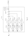
Fig. 5 : Configuration diagram of the q-axis magnetic flux gain calculation unit (N=4) in the example. -
Fig. 6 : Configuration diagram of the magnetic flux gain calculation unit (N=4) for the d-axis in Example 1. -
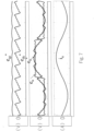
Fig. 7 :Control characteristics 2. -
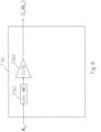
Fig. 8 : Configuration diagram of the q-axis magnetic flux gain calculation unit (N=1) in Example 1. -
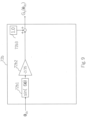
Fig. 9 : Configuration diagram of the magnetic flux gain calculation unit (N=1) for the d-axis in Example 1. -
Fig. 10 :Control characteristic 3. -
Fig. 11 : Configuration diagram for checking the manifestation of the invention. -
Fig. 12 : System configuration diagram of the power converter apparatus and other equipment in Example 2. -
Fig. 13 : System configuration diagram of the power converter apparatus and other equipment in Example 3. -
Fig. 14 : System configuration diagram of the power converter apparatus and other equipment in Example 4. - The following drawings are used to explain this example in detail. The same reference numbers are used for common configurations in each figure. The examples described below are not limited to the illustrated examples.
-
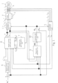
Fig. 1 shows a system configuration diagram with power converter apparatus and magnet motor in Example 1. -
Magnet motor 1 outputs motor torque that is a composite of the torque component due to the magnetic flux of the permanent magnet and the torque component due to the inductance of the armature winding. -
Power converter 2 is equipped with semiconductor devices as switching elements.Power converter 2 inputs 3-phase AC voltage command value vu*, vv*, vw* and outputs voltage values proportional to 3-phase AC voltage command value vu*, vv*, vw* based on the output ofpower converter 2,magnet motor 1 is driven, and the output voltage value, output frequency value, and output current value of magnet motor! are controlled variably. IGBT (Insulated gate bipolar transistor) may be used as switching elements. -
DC power supply 3 supplies DC voltage and DC current to power converter2. - The
current detector 4 outputs iuc, ivc, and iwc, which are the detected values of the alternating current iu, iv, and iw of the threephase magnet motor 1. Thecurrent detector 4 detects the alternating current of two of the threephase magnet motor 1, for example, phase u and phase w. The alternating current of phase v may be calculated from the AC condition (iu+iv+iw=0) to be iv=-(iu+iw). - In this example, the
current detector 4 is shown in the power converter apparatus, but it can also be located outside the power converter apparatus. - The control unit is equipped with a
coordinate conversion unit 5, speed controlarithmetic unit 6, magnetic fluxgain calculation unit 7, vector controlarithmetic unit 8, phaseerror estimation unit 9, frequency andphase estimation 10, and coordinate conversion unit 11 described below.Unit 8, phaseerror estimation unit 9, frequency andphase estimation 10, and coordinate conversion unit 11. - The control unit controls the output of power converter2 so that the output voltage value, output frequency value, and output current of magnet motor1 are controlled variably.
- The control unit is composed of microcomputers and semiconductor integrated circuits (arithmetic and control means) such as DSP (digital signal processor), etc. Any or all of the control unit can be composed of hardware such as ASIC (Application Specific Integrated Circuit) and FPGA (Field Programmable Gate Array).
- The CPU (Central Processing Unit) of the control unit reads the program stored in the memory or other recording device and executes the processing of each part of the coordinate conversion unit5 and other parts described above.
- Next, each component of the control unit is explained.
- Coordinate
conversion unit 5 outputs current sense values idc and iqc for the d- and q-axes from the three-phase alternating current iu, iv, iw detection values iuc, ivc, iwc and phase estimate value θdc. - The speed control
arithmetic unit 6 calculates the torque command value τ* based on the frequency command value ωr* and frequency estimates ωdc and divides it by the torque coefficient to output the q-axis current command value iq* - The magnetic flux
gain calculation unit 7 outputs the gains Gd(qdc) and Gq(qdc) of the d-axis and q-axis magnetic flux components that vary with phase based on the phase estimate value θdc - The vector control
arithmetic unit 8 outputs current command value id*, iq*, current sense value idc, iqc, frequency estimates ωdc of the d-axis and q-axis, the electrical circuit parameters ofmagnet motor 1 and voltage command value vdc** and vqc** are calculated based on the gains Gd(qdc) and Gq(qdc) of the magnetic flux components of the q-axis and d-axis. - The phase
error estimation unit 9 outputs the estimated phase error Δθc ,which is the deviation between the phase estimate value θdc ,which is the phase of the control, and the phase θd of the magnet motor1 by using the control axis d-axis and q-axis voltage command value vdc**, vqc**, frequency estimates ωdc, current sense value idc, iqc and electrical circuit parameters ofmagnet motor 1. - The frequency and
phase estimation 10 outputs the frequency estimate ωdc and phase estimate value θdc based on the phase error estimates Δθc - Coordinate conversion unit 11 outputs 3-phase AC voltage command value vu*, vv*, and vw* from d-axis and q-axis voltage command value vdc** and vqc** and phase estimate value θdc.
- First, the basic operation of the sensor-less vector control system when using the magnetic flux
gain calculation unit 7, which is a feature of this example is described. - The speed control
arithmetic unit 6 calculates the torque command τ* and the current command value iq* of the q-axis according toFormula 1 by proportional and integral control so that the frequency estimates ωdc follow the frequency command value ωr*.
[Formula 1]
- Ksp : proportional gain of speed control, Ksi : integral gain of speed control, Pm : polar logarithm,
- Ke : Induced voltage coefficient, Ld : d-axis inductance, Lq : q-axis inductance,
- *:set value, s is Laplace operator
- The magnetic flux
gain calculation unit 7 and vector controlarithmetic unit 8 inFigure 1 are explained. -
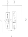
Figure 2 shows the block diagram of the magnetic fluxgain calculation unit 7, which consists of the q-axis magnetic fluxgain calculation unit 71 and the d-axis magnetic fluxgain calculation unit 72. fluxgain calculation unit 72 for the d-axis. - The q-axis magnetic flux
gain calculation unit 71 calculates the sine function of the phase estimate according toFormula 2 using the phase estimate value θdc and outputs the q-axis magnetic flux gain Gq(θdc).
[Formula 2]
- The magnetic flux
gain calculation unit 72 of d-axis calculates the sine function of the phase estimate according toFormula 3 using the phase estimate value θdc and outputs the magnetic flux gain Gq(θdc) of d-axis. N is the order and a natural number.
[Formula 3]
-
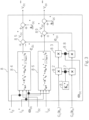
Figure 3 shows the block diagram of vector controlarithmetic unit 8. First, the d-axis voltage command value of vector controlarithmetic unit 8 is explained. - The permanent magnet motor1 induced voltage coefficient Ke* 81 and q-axis magnetic flux gain Gq(θdc) are input to
multiplier 82. - The output of
multiplier 82 is input to multiplier 83 together with frequency estimates ωdc and its output is d-axis induced voltage command value edc* shown inFormula 4. - Here, frequency estimates ωdc is used as the input to multiplier83, but it can be modified so that instead of frequency estimates ωdc, frequency command value ωr* is used as the input to multiplier 83 and multiplied with the output of
multiplier 82.
[Formula 4]
- The induced voltage coefficient Ke* 81 is a constant value and is not a data such as induced voltage that varies with rotational position. In addition, the calculation section 84 calculates d-axis voltage command value vdc0* according to
Formula 5 by using the electrical circuit parameters of thepermanent magnet motor 1, such as the set value of winding resistance R*, the set value of q-axis inductance Lq*, the d-axis current command value id*, the q-axis current command value iq*, frequency estimates ωdc. - The output vdc0* of arithmetic unit 84 is input to adder 85 together with the d-axis induced voltage command value edc*, and the output of adder 85 is the d-axis voltage command value reference value vdc* shown in
Formula 6.
[Formula 5]
[Formula 6]
- Second, the q-axis voltage command value of vector control
arithmetic unit 8 is explained. - The induced voltage coefficient Ke* 81 of
permanent magnet motor 1 and the magnetic flux gain Gd(θdc) of the d-axis are input tomultiplier 87. - The output of
multiplier 87 is input tomultiplier 88 together with frequency estimate ωdc. - The output of
multiplier 88 is the q-axis induced voltage command value eqc* shown inFormula 7. - Here, frequency estimates ωdc is used as the input of
multiplier 88, but it can be modified so that frequency command value ωr* is used as the input ofmultiplier 88 instead of frequency estimates ωdc and multiplied with the output of multiplier87.
[Formula 7]
- In addition, the
calculation section 86 calculates the electrical circuit parameters of thepermanent magnet motor 1 of winding resistance setting R*, d-axis inductance setting Ld*, d-axis current command value id*, q-axis current command value iq*, frequency estimates ωdc are used to calculate the q-axis voltage command value vqc0* according toFormula 8. - The output vqc0* of
arithmetic unit 86 is input to adder 89 together with the q-axis induced voltage command value eqc*. The output ofadder 89 is the reference value vqc* of the q-axis voltage command value shown inFormula 9.
[Formula 8]
[Formula 9]
- Third, the current control operation of the vector control is explained. d-axis and q-axis voltage correction values Δvdc and Δvqc are calculated according to
Formula 10 by proportional control and integral control so that the current sense values idc and iqc of each component follow the current command values id* and iq* of the d and q axes, respectively.
[Formula 10]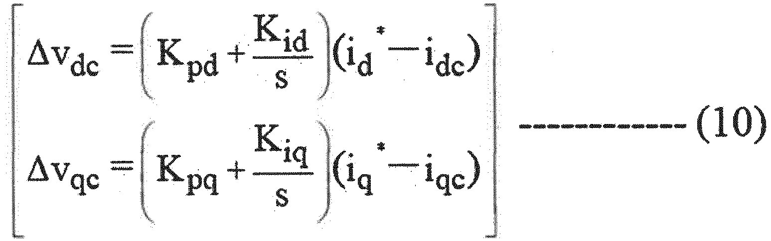
- Kpd: proportional gain of current control of d-axis, Kid: integral gain of current control of d-axis
- Kpq: proportional gain of q-axis current control, Kiq: integral gain of q-axis current control
- In addition, the d-axis and q-axis voltage command value vdc** and vqc** are calculated according to Formula 11.
[Formula 11]
- The phase
error estimation unit 9 calculates the phase error estimates Δθ based on the d-axis and q-axis voltage command value vdc**, vqc**, current sense value idc, iqc and the electrical circuit parameters of magnet motor1 (R*, Lq*), frequency estimation ωdc and the extended induced voltage formula (Formula 12).
[Formula 12]
- Frequency and
phase estimation 10 will be described. - To make the phase error estimates Δθc follow the command value Δθc*, frequency estimates ωdc are calculated according to
Formula 13 by P(proportional) + I(integral) control operation, and phase estimates value θdc are calculated according to Formula 14 by I control operation.
[Formula 13]
Kppll: proportional gain of PLL control, Kipll: integral gain of PLL control
[Formula 14]
- The principle of the sinusoidal motor current in the present invention is explained next.
-
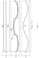
Fig. 4 shows control characteristic 1 when the d-axis and q-axis magnetic flux gains are Gq(θdc) = 0 and Gd(θdc) = 1, respectively. This is the simulation result of driving magnet motor1 with square wave induced voltage. - In
Fig. 4 , the upper row displays the d-axis and q-axis induced voltage command value edc* and eqc*, the middle row displays the square wave induced voltage eu of phase u and the command value equivalent eu* of the induced voltage of phase u, and the lower row displays the alternating current iu of phase u. Since Gq(θdc) = 0 and Gd(θdc) = 1 the d-axis and q-axis induced voltage command values edc* and eqc* are Formula 15 and eu* is a sine wave.
[Formula 1 5]
- As a result, the alternating current iu of phase u is not a sinusoidal current, but a distorted current with superimposed 5th and 7th harmonics.
- In using the magnetic flux
gain calculation unit 7 of the present invention, the order N shown inFormula 2 is set to 4, for example.Fig. 5 shows the block (compensation up to the 24th harmonic) of the q-axis magnetic flux gain calculation unit 71a with N=4. - The phase of n=1 is calculated by 71a1 and the magnetic flux gain is calculated by 71a2. n=2 is calculated by 71a3 and the magnetic flux gain is calculated by 71a4. n=3 is calculated by 71a5 and the magnetic flux gain is calculated by 71a6. The phase of n=4 is calculated by 71a7 and the magnetic flux gain is calculated by 71a8. These are uniquely determined, and the signal obtained by adding the results of operations n=1 to n=4 is Gq(θdc).
- Next, set N=4 as shown in
Formula 3.Fig. 6 shows the block diagram (compensation up to the 24th harmonic) of the d-axis magnetic flux gain calculation unit 72a set' to N=4. - The phase of n=1 is calculated by 72a1 and the magnetic flux gain is calculated by 72a2. n=2 is calculated by 72a3 and the magnetic flux gain is calculated by 72a4. n=3 is calculated by 72a5 and the magnetic flux gain is calculated by 72a6. The phase of n=4 is calculated by 72a7 and the magnetic flux gain is calculated by 72a8. The constant "1" is set in the setting section 72a9. n=1 to n=4 and the constant "1" are added to obtain the signal Gd(θdc).
-
Fig. 7 shows thecontrol characteristics 2 when magnetic fluxgain calculation unit 7 is used (N=4 is used). This is the simulation result of drivingmagnet motor 1 whose induced voltage is a square wave. - In
Fig. 7 , the top row shows the d-axis and q-axis induced voltage command value edc* and eqc*, the middle row shows the square wave induced voltage eu of phase u and the command value equivalent eu* of the induced voltage of phase u, and the bottom row shows the alternating current iu of phase u. Gq(θdc) is shown the block diagram inFig. 5 , Gd(θdc) shown in the block diagram inFig. 6 . - The d-axis and q-axis induced voltage command values edc* and eqc* include up to 24th harmonic components, and the induced voltage command value equivalent eu* is a waveform far from a sine wave containing harmonics, but the alternating current iu is a sinusoidal current.
- The effect of the invention is evident. In the case of
Fig. 4 , the d-axis induced voltage command value edc* is zero, but the d-axis induced voltage command value edc* is not zero as inFig. 4 , but has a shape that includes harmonic components (sawtooth wave). This is one of the characteristics. - Furthermore, set N=1 in the magnetic flux
gain calculation unit 7 inFig. 1 . (InFormula 2, set N=1.Fig. 8 shows the block of magnetic fluxgain calculation unit 71b for the q-axis set to N=1 (compensation of 6th harmonic). n=1 phase is calculated in calculation unit 71b1 and magnetic flux gain is calculated in calculation unit 71b2. The signal is Gq(θdc). - Next, set N=1 in
Formula 3.Fig. 9 shows the block of the magnetic fluxgain calculation unit 72b for the d-axis set to N=1 (compensation of 6th harmonic). n=1 phase is calculated in calculation unit 72b1 and magnetic flux gain in calculation unit 72b2. The constant "1" is set in the setting unit 72b3. The additive signal with constant "1" and n=1 is Gd(θdc). -
Fig. 10 shows thecontrol characteristics 3 when the magnetic fluxgain calculation unit 7 is used (N=1 is used). This is the simulation result of driving magnet motor1 whose induced voltage is a square wave. - In
Fig. 10 , the upper row displays the d-axis and q-axis induced voltage command values edc* and eqc*, the middle row displays the square wave induced voltage of phase u eu and the command value equivalent eu* of the induced voltage of phase u, and the lower row displays the alternating current iu of phase u. Gq(θdc) is the block diagram inFig. 8 , Gd(θdc) is the case of the calculation in the block diagram inFig. 9 . - The d-axis and q-axis induced voltage command values edc* and eqc* contain 6th harmonic components, and the induced voltage command value equivalent eu* is far from a sinusoidal waveform, but the alternating current iu of phase u is somewhat distorted compared to a sinusoidal waveform. The effect of this invention is obvious. To confirm the effect of this example, the order N was set to N=4 and N=1 as an example. N is a natural number, and the larger the value of N, the closer the alternating current of the u-phase can be to a sine wave.
- According to this example, the current of magnet motor can be made sinusoidal without having induced voltage data by a general-purpose controller or other means.
- Here, the verification method when this example is adopted is explained using
Fig. 11 .voltage detector 21 and current detector 22 are attached to thepower converter apparatus 20 that drivesmagnet motor 1, andencoder 23 is attached to the shaft ofmagnet encoder 23 is attached to theshaft ofmagnet motor 1. - The voltage detection values of 3-phase AC (vuc, vvc, vwc) and current sense values of 3-phase AC (iuc, ivc, iwc), which are outputs of
voltage detector 21, and the position detection values θ, which are outputs of encoder, are input to thecalculation section 24, for vector voltage and current components, vdcc, vqcc, idcc and iqcc of the vector current components and the detected value ωrc, which is the derivative of position θ, are calculated. - The
observation section 25 of each part waveform calculates the d-axis and q-axis induced voltages edc ^ and eqc ^ using Formula 16.
[Formula 16]
- By observing the voltage waveforms of edc ^ and eqc ^, it is obvious that the invention has been adopted.
-
Fig. 12 shows the system configuration diagram with power converter apparatus and magnet motor in Example 2. - While Example 1 modified the d-q-axis voltage command value of the rotary seat coordinates, this example modifies the U-V-W voltage command value of the fixed coordinates.
- In
Fig. 12 ,magnet motor 1,power converter 2,DC power supply 3,current detector 4, coordinateconversion unit 5, speed controlarithmetic unit 6, magnetic fluxgain calculation unit 7, phaseerror estimation unit 9, frequency andphase estimation 10, and coordinate conversion unit 11 are the same as inFig. 1 . The vector controlarithmetic unit 8 inFig. 3 without the induced voltage coefficients Ke* 81,multiplier 82, multiplier 83, adder 85,multiplier 87,multiplier 88, andadder 89 is shown inFig. 12. Fig. 12 shows the vector controlarithmetic unit 8. - 12 is the coordinate conversion unit from rotational coordinates to fixed coordinates and 13 is the adder. Coordinate
conversion unit 12 replaces the operations in vector controlarithmetic unit 8 inFig. 3 . magnetic flux gain Gq(θdc) and d-axis magnetic flux gain Gd(θdc) to calculate the d-axis and q-axis induced voltage command values edc* and eqc*. Then, coordinateconversion unit 12 outputs three-phase induced voltage command values eu*, ev*, and ew* from the d-axis and q-axis induced voltage command values edc*, eqc* and the phase estimate value θdc. - In this example, the d-axis and q-axis induced voltage command values edc* and eqc* are converted to 3-phase induced voltage command values eu*, ev*, and ew* to modify the 3-phase voltage command values.
- According to this example, a sinusoidal current can be realized as in Example 1.
-
Fig. 13 is a system configuration diagram with power converter apparatus and magnet motor in Example 3. InFig. 13 ,magnet motor 1,power converter 2,DC power supply 3,current detector 4, coordinateconversion unit 5, speed controlarithmetic unit 6, magnetic fluxgain calculation unit 7, vector controlarithmetic unit 8, phaseerror estimation unit 9, frequency andphase estimation 10, and coordinate conversion unit 11 is identical toFig. 1 .14 is an IOT(Internet of Things) controller that can perform machine learning. - Example 1 is a configuration in which the drive mode (square wave drive or sine wave drive) and parameters such as the order N of
Formula 2 orFormula 3 are set in the controller (microcomputer or other control unit) of the power converter. - When the control unit in Example 3 receives an instruction for sinusoidal drive, it sets the gain of the q-axis flux component to 0 and the gain of the d-axis flux component to 1.
- When a square wave drive instruction is received, the control unit calculates the gain of said magnetic flux component of the q-axis as a sine function of the phase estimate based on
Formula 2. Furthermore, the control unit calculates the gain of the magnetic flux component of the d-axis as a sinusoidal function of the phase estimate based onFormula 3, and subtracts the result of the calculation from 1. - In this example, the control unit feeds back the voltage command value vdc**, vqc** and current sense value idc, iqc, phase error estimates Δθc to the upper IOT CONTROLLER 14. IOT CONTROLLER 14 analyzes the signals such as voltage command, value vdc** , vqc** and current sense value idc, iqc, phase error estimates Δθc by machine learning, and based on the machine learning, the control unit re-sets the drive mode and order N to the
power converter 2 controller. - According to this example, a sinusoidal current can be realized as in Example 1.
-
Fig. 14 shows the system configuration diagram with power converter apparatus and magnet motor in Example 4. - This example is the application of this system to a magnet motor drive system.
- In
Fig. 14 , thecomponents magnet motor 1, coordinateconversion unit 5, speed controlarithmetic unit 6, magnetic fluxgain calculation unit 7, vector controlarithmetic unit 8, phaseerror estimation unit 9, frequency andphase estimation 10, and coordinate conversion unit 11 are identical to those inFig. 1 . -
Magnet motor 1, a component ofFig. 1 , is driven bypower converter apparatus 20.Power converter apparatus 20 consists of coordinateconversion unit 5, speed controlarithmetic unit 6, magnetic fluxgain calculation unit 7, vector controlarithmetic unit 8, vector controlarithmetic unit 8, phaseerror estimation unit 9, frequency andphase estimation unit 10, and magnetic flux gain calculation unit 11.arithmetic unit 6, magnetic fluxgain calculation unit 7, vector controlarithmetic unit 8, phaseerror estimation unit 9, frequency andphase estimation 10 and coordinate conversion unit 11 are implemented as software 20a. Thepower converter apparatus 20 has thepower converter 2,DC power supply 3, and current detector4 ofFig. 1 implemented as hardware. - From the display screen of a higher-level device such as a digital operator 20b,
personal computers 28,tablets 29,smartphones 30, etc., the "drive mode "26 to set the square wave drive or sinusoidal drive of software 20a,Formula 2 andFormula 3, the "order N 27" can be set and changed. - If this example is applied to a magnet motor drive system, the current of magnet motor, which is a square wave induced voltage, can be controlled sinusoidally. The "drive mode" and "N" may be set on a field bus such as a programmable logic controller, a local area network connected to a computer, or an IOT CONTROLLER.
- The calculation results in the calculation sections 71a2, 71a4, 71a6, 71a8 of the magnetic flux gain in
Fig. 5 and the calculation sections 72a2, 72a4, 72a6, 72a8 inFig. 6 in Example 1 are constants, but these constants may be rewritten. - So far, in Examples 1 through 4, we have applied this method to position sensor-less control, but it can also be applied to vector control with an encoder attached to the shaft axis of
magnet motor 1. - Furthermore, in Examples 1 through 4, voltage correction values Δvdc and Δvqc were created from current command value id*, iq* and current sense value idc, iqc, and the operation shown in Formula 11 was performed to add this voltage correction value and the,voltage reference value for vector control. Not only that, from current command value id*, iq* and current sense value idc, iqc, the intermediate current command value id**, iq** shown in Formula 17 used for vector control calculation were created, and frequency estimates ωdc and the vector control operation shown in
Formula 18 may be performed using the electrical circuit parameters ofmagnet motor 1.
[Formula 1 7]
[Formula 18]
Kpd1 : proportional gain of current control of dc axis, Kid1 : integral gain of current control of dc axis, Kpq1 : proportional gain of current control of qc axis, Kiq1 : integral gain of current control of qc axis, Td : electrical time constant of d axis (Ld/R), Tq : electrical time constant of q axis (Lq/R) - Alternatively, from the current command value id* and iq* and the current sense value idc and iqc, the voltage correction values Δvd_p* for the proportional component of d-axis, Δvd_i* for the integral component of d-axis, Δvq_p* for the proportional component of q-axis and the modified values Δvq_i* of the integral component of the q-axis are created using Formula 19.
- Then, the vector control operation shown in
Formula 20 using the frequency estimates ωdc and the electrical circuit parameters ofmagnet motor 1 may be performed.
[Formula 1 9]
Kpd2 : proportional gain of d-axis current control, Kid2 : integral gain of d-axis current control, Kpq2 : proportional gain of q-axis current control, Kiq2 : integral gain of q-axis current control
[Formula 20]
- The primary delay signal iqctd of the d-axis current command value id* and q-axis current sense value iqc, frequency , estimates ωdc and the electrical circuit parameters of
magnet motor 1 may be used to perform the vector control operation shown inFormula 21.
[Formula 21]
- In Examples 1 to 4, the switching device that constitutes
power converter 2 may be a Si(silicon) semiconductor device or a wide bandgap semiconductor device such as SiC(silicon carbide) or GaN(gallium nitride). -
- 1 magnet motor
- 2 power converter
- 3 DC power supply
- 4 current detector
- 5 coordinate conversion unit
- 6 speed control arithmetic unit
- 7 magnetic flux gain calculation unit
- 8 vector control arithmetic unit
- 9 phase error estimation unit
- 10 frequency and phase estimation
- 11 coordinate conversion unit
- 12 coordinate conversion unit
- 13 Addition section, Adder
- 14 IOT controller
- 20 power converter apparatus
- 20a power converter apparatus software
- 20b digital operator of power converter apparatus
- 21 voltage detector
- 22. current detector
- 2 encoder
- 24 calculation part of vector current component
- 25 observation of current waveforms of each part
- 26 control mode
- 27 N (degree)
- 28 personal computers
- 29 tablet
- 30 smartphones
- id* d-axis current command value
- iq* q-axis current command value
- ωr* frequency command value
- ωdc frequency estimates
- ωr magnet motor frequency
- Gq (θdc ) q-axis magnetic flux component gain
- Gd (θdc ) d-axis magnetic flux component gain
- edc* d-axis induced voltage command value
- edc* q-axis induced voltage command value
- vdc* vdc** vdc** vdc*** vdc**** vdc***** d-axis voltage command value
- vqc* vqc** vqc*** vqc**** vqc***** q-axis voltage command value
- Δθc phase error estimates
Claims (10)
- A power converter apparatus comprising:a power converter that outputs signal to the magnet motor to vary the output frequency, output voltage and output current of the magnet motor,a control unit controls the power converter,wherein the control unitcalculating the gain of the magnetic flux component of the q-axis, which varies with the phase of the magnet motor,calculating the d-axis induced voltage command value based on a value of the induced voltage coefficient, frequency estimates or frequency command value, and the gain of the flux component of the q-axis.
- A power converter apparatus according to claim 1,the control unit is calculating the gain of the magnetic flux component of the d-axis, which varies with the phase of the magnet motor,calculating the q-axis induced voltage command value based on the set value of the induced voltage coefficient, frequency estimates or frequency command value, and the gain of the d-axis magnetic flux component.
- A power converter apparatus according to claim 1,
the control unit is calculating the command values of the induced voltages of the three phases based on the command values of the induced voltages of the d-axis and the phase estimate value. - A power converter apparatus according to claim 2,
the control unit is calculating the command values of the induced voltages of the three phases based on the command value of the induced voltage of the d-axis, the command value of the induced voltage of the q-axis, and the phase estimate value. - A power converter apparatus according to claim 1,
the control unit is calculating the gain of said flux component of the q-axis as a sine function of the phase estimate value. - A power converter apparatus according to claim 2,the control unit is calculating the gain of said flux component of the d-axis as a sine function of the phase estimate value,and subtracting the result from 1.
- A power converter apparatus according to claim 2,the control unit is,receiving instructions on whether the magnet motor is to be driven by a sinusoidal or square wave drive,when the instruction indicating a sinusoidal drive,the gain of said flux component of the q-axis is set to 0 and the gain of said flux component of the d-axis is set to 1, when the instruction indicating drive square wave drive, obtaining the gain of said flux component of the q-axis by computing as a sine function of the phase estimate value, and obtaining the gain of said flux component of the d-axis by computing as a sine function of the phase estimate and subtracting the result of that calculation from 1.
- A power converter apparatus according to claim 2,when the magnet motor is directed to select a square wave drive,the control unit is,selecting the order N in the sinusoidal function of the phase estimate value,calculating the gain of said flux component in the q-axis and the gain of said flux component in the d-axis based on said order N.
- A power converter apparatus according to claim 2,the control unit is,being fed back voltage command value, current sense value, phase error estimates and estimated frequency to the host device for analysis,automatically sets the order N in the sinusoidal function of the phase estimate value required to calculate the gain of said flux component in the q-axis or the gain of said flux component in the d-axis, based on analysis result from the host device.
- A power converter apparatus according to claim 1,the control unit is,receiving direction of the order N in the sinusoidal function of the phase estimate required to calculate the gain of the flux component of the q-axis or the flux component of the d-axis,or whether the magnet motor is driven sinusoidally or square wave from digital operators or personal computers,setting and changing control based on the direction.
Applications Claiming Priority (2)
| Application Number | Priority Date | Filing Date | Title |
|---|---|---|---|
| JP2021107665A JP2023005629A (en) | 2021-06-29 | 2021-06-29 | Power conversion device |
| PCT/JP2021/041409 WO2023276181A1 (en) | 2021-06-29 | 2021-11-10 | Power conversion device |
Publications (2)
| Publication Number | Publication Date |
|---|---|
| EP4366152A1 true EP4366152A1 (en) | 2024-05-08 |
| EP4366152A4 EP4366152A4 (en) | 2025-04-16 |
Family
ID=84691096
Family Applications (1)
| Application Number | Title | Priority Date | Filing Date |
|---|---|---|---|
| EP21948484.7A Withdrawn EP4366152A4 (en) | 2021-06-29 | 2021-11-10 | Power conversion device |
Country Status (5)
| Country | Link |
|---|---|
| US (1) | US12334847B2 (en) |
| EP (1) | EP4366152A4 (en) |
| JP (1) | JP2023005629A (en) |
| CN (1) | CN116746049A (en) |
| WO (1) | WO2023276181A1 (en) |
Families Citing this family (1)
| Publication number | Priority date | Publication date | Assignee | Title |
|---|---|---|---|---|
| JP2024157737A (en) * | 2023-04-26 | 2024-11-08 | 株式会社日立産機システム | Power Conversion Equipment |
Family Cites Families (12)
| Publication number | Priority date | Publication date | Assignee | Title |
|---|---|---|---|---|
| JP4154149B2 (en) * | 2001-12-28 | 2008-09-24 | 株式会社東芝 | Vector control inverter device |
| JP2009017676A (en) * | 2007-07-04 | 2009-01-22 | Aisin Seiki Co Ltd | Control device and control method for synchronous motor |
| JP5259241B2 (en) * | 2008-04-23 | 2013-08-07 | 株式会社東芝 | Motor controller, motor drive system, washing machine, air conditioner, method of changing the amount of magnetization of a permanent magnet motor |
| JP5417195B2 (en) * | 2010-01-19 | 2014-02-12 | 国産電機株式会社 | Torque ripple suppression control device for permanent magnet motor, electric power steering system |
| JP2014166082A (en) * | 2013-02-27 | 2014-09-08 | Hitachi Appliances Inc | Motor control device and air conditioner using the same |
| US9525376B2 (en) | 2014-05-13 | 2016-12-20 | Gbox, Llc | Wound field synchronous machine with resonant field exciter |
| CN107431452B (en) | 2015-04-10 | 2020-03-31 | 株式会社美姿把 | Motor drive device and control method for motor drive device |
| JP6516537B2 (en) * | 2015-04-10 | 2019-05-22 | 株式会社ミツバ | Motor drive device and control method of motor drive device |
| JP6457472B2 (en) * | 2016-12-14 | 2019-01-23 | ファナック株式会社 | Control system and machine learning device |
| JP7032250B2 (en) * | 2018-06-28 | 2022-03-08 | 株式会社日立産機システム | Power converter |
| JP7489899B2 (en) * | 2019-10-18 | 2024-05-24 | 株式会社安川電機 | Event estimation system and event estimation method |
| JP7095760B1 (en) * | 2021-01-14 | 2022-07-05 | 株式会社安川電機 | Control device, magnetic flux estimation device and magnetic flux estimation method |
-
2021
- 2021-06-29 JP JP2021107665A patent/JP2023005629A/en active Pending
- 2021-11-10 WO PCT/JP2021/041409 patent/WO2023276181A1/en not_active Ceased
- 2021-11-10 CN CN202180090523.8A patent/CN116746049A/en active Pending
- 2021-11-10 US US18/273,844 patent/US12334847B2/en active Active
- 2021-11-10 EP EP21948484.7A patent/EP4366152A4/en not_active Withdrawn
Also Published As
| Publication number | Publication date |
|---|---|
| US12334847B2 (en) | 2025-06-17 |
| JP2023005629A (en) | 2023-01-18 |
| CN116746049A (en) | 2023-09-12 |
| US20240079982A1 (en) | 2024-03-07 |
| WO2023276181A1 (en) | 2023-01-05 |
| EP4366152A4 (en) | 2025-04-16 |
Similar Documents
| Publication | Publication Date | Title |
|---|---|---|
| JP5155344B2 (en) | Electric motor magnetic pole position estimation device | |
| CN107660325B (en) | Control device for AC rotating machine and electric power steering device | |
| CN104584419B (en) | Control device of electric motor | |
| EP1460758B1 (en) | Vector control method and apparatus | |
| CN104167960B (en) | Synchronous motor control device | |
| JP6374037B2 (en) | Motor control device | |
| EP3817218A1 (en) | Power conversion apparatus | |
| EP4072005A1 (en) | Power conversion device | |
| US11437944B2 (en) | Power conversion device | |
| CN106257822A (en) | Controller for motor, flux demand generating means and flux demand generate method | |
| US12334847B2 (en) | Power converter apparatus | |
| EP4340211A1 (en) | Power conversion device | |
| JP2008206330A (en) | Device and method for estimating magnetic pole position of synchronous electric motor | |
| WO2012026568A1 (en) | Single-phase signal input device and system interconnection device | |
| KR20200059507A (en) | Inverter control apparatus | |
| JP2020010566A (en) | Motor controller | |
| JP4722002B2 (en) | PWM inverter control device, PWM inverter control method, and refrigeration air conditioner | |
| JP6848680B2 (en) | Synchronous motor control device | |
| JP6729249B2 (en) | Power converter controller | |
| US10622930B2 (en) | Motor control device and control method | |
| EP4075665B1 (en) | Power converter | |
| EP4686078A1 (en) | Motor control device | |
| JP5456873B1 (en) | Synchronous machine controller | |
| JP6880448B2 (en) | Synchronous motor control device | |
| EP4704330A1 (en) | Power conversion device |
Legal Events
| Date | Code | Title | Description |
|---|---|---|---|
| STAA | Information on the status of an ep patent application or granted ep patent |
Free format text: STATUS: THE INTERNATIONAL PUBLICATION HAS BEEN MADE |
|
| PUAI | Public reference made under article 153(3) epc to a published international application that has entered the european phase |
Free format text: ORIGINAL CODE: 0009012 |
|
| STAA | Information on the status of an ep patent application or granted ep patent |
Free format text: STATUS: REQUEST FOR EXAMINATION WAS MADE |
|
| 17P | Request for examination filed |
Effective date: 20240129 |
|
| AK | Designated contracting states |
Kind code of ref document: A1 Designated state(s): AL AT BE BG CH CY CZ DE DK EE ES FI FR GB GR HR HU IE IS IT LI LT LU LV MC MK MT NL NO PL PT RO RS SE SI SK SM TR |
|
| DAV | Request for validation of the european patent (deleted) | ||
| DAX | Request for extension of the european patent (deleted) | ||
| A4 | Supplementary search report drawn up and despatched |
Effective date: 20250314 |
|
| RIC1 | Information provided on ipc code assigned before grant |
Ipc: H02P 21/18 20160101ALI20250310BHEP Ipc: H02P 21/14 20160101ALI20250310BHEP Ipc: H02P 21/05 20060101ALI20250310BHEP Ipc: H02P 21/00 20160101ALI20250310BHEP Ipc: H02P 21/26 20160101ALI20250310BHEP Ipc: H02P 6/10 20060101AFI20250310BHEP |
|
| STAA | Information on the status of an ep patent application or granted ep patent |
Free format text: STATUS: THE APPLICATION IS DEEMED TO BE WITHDRAWN |
|
| 18D | Application deemed to be withdrawn |
Effective date: 20251002 |