EP4366089A1 - Antenna apparatus and base station antenna - Google Patents
Antenna apparatus and base station antenna Download PDFInfo
- Publication number
- EP4366089A1 EP4366089A1 EP22831973.7A EP22831973A EP4366089A1 EP 4366089 A1 EP4366089 A1 EP 4366089A1 EP 22831973 A EP22831973 A EP 22831973A EP 4366089 A1 EP4366089 A1 EP 4366089A1
- Authority
- EP
- European Patent Office
- Prior art keywords
- linear array
- units
- antenna
- staggered
- unit
- Prior art date
- Legal status (The legal status is an assumption and is not a legal conclusion. Google has not performed a legal analysis and makes no representation as to the accuracy of the status listed.)
- Pending
Links
Images


Classifications
-
- H—ELECTRICITY
- H01—ELECTRIC ELEMENTS
- H01Q—ANTENNAS, i.e. RADIO AERIALS
- H01Q21/00—Antenna arrays or systems
-
- H—ELECTRICITY
- H01—ELECTRIC ELEMENTS
- H01Q—ANTENNAS, i.e. RADIO AERIALS
- H01Q1/00—Details of, or arrangements associated with, antennas
- H01Q1/12—Supports; Mounting means
- H01Q1/22—Supports; Mounting means by structural association with other equipment or articles
- H01Q1/24—Supports; Mounting means by structural association with other equipment or articles with receiving set
- H01Q1/241—Supports; Mounting means by structural association with other equipment or articles with receiving set used in mobile communications, e.g. GSM
- H01Q1/246—Supports; Mounting means by structural association with other equipment or articles with receiving set used in mobile communications, e.g. GSM specially adapted for base stations
-
- H—ELECTRICITY
- H01—ELECTRIC ELEMENTS
- H01Q—ANTENNAS, i.e. RADIO AERIALS
- H01Q1/00—Details of, or arrangements associated with, antennas
- H01Q1/36—Structural form of radiating elements, e.g. cone, spiral, umbrella; Particular materials used therewith
-
- H—ELECTRICITY
- H01—ELECTRIC ELEMENTS
- H01Q—ANTENNAS, i.e. RADIO AERIALS
- H01Q21/00—Antenna arrays or systems
- H01Q21/0006—Particular feeding systems
- H01Q21/0037—Particular feeding systems linear waveguide fed arrays
- H01Q21/0043—Slotted waveguides
- H01Q21/005—Slotted waveguides arrays
-
- H—ELECTRICITY
- H01—ELECTRIC ELEMENTS
- H01Q—ANTENNAS, i.e. RADIO AERIALS
- H01Q21/00—Antenna arrays or systems
- H01Q21/06—Arrays of individually energised antenna units similarly polarised and spaced apart
- H01Q21/061—Two dimensional planar arrays
- H01Q21/064—Two dimensional planar arrays using horn or slot aerials
-
- H—ELECTRICITY
- H01—ELECTRIC ELEMENTS
- H01Q—ANTENNAS, i.e. RADIO AERIALS
- H01Q21/00—Antenna arrays or systems
- H01Q21/06—Arrays of individually energised antenna units similarly polarised and spaced apart
- H01Q21/061—Two dimensional planar arrays
- H01Q21/065—Patch antenna array
-
- H—ELECTRICITY
- H01—ELECTRIC ELEMENTS
- H01Q—ANTENNAS, i.e. RADIO AERIALS
- H01Q21/00—Antenna arrays or systems
- H01Q21/06—Arrays of individually energised antenna units similarly polarised and spaced apart
- H01Q21/08—Arrays of individually energised antenna units similarly polarised and spaced apart the units being spaced along or adjacent to a rectilinear path
-
- H—ELECTRICITY
- H01—ELECTRIC ELEMENTS
- H01Q—ANTENNAS, i.e. RADIO AERIALS
- H01Q3/00—Arrangements for changing or varying the orientation or the shape of the directional pattern of the waves radiated from an antenna or antenna system
- H01Q3/26—Arrangements for changing or varying the orientation or the shape of the directional pattern of the waves radiated from an antenna or antenna system varying the relative phase or relative amplitude of energisation between two or more active radiating elements; varying the distribution of energy across a radiating aperture
-
- H—ELECTRICITY
- H01—ELECTRIC ELEMENTS
- H01Q—ANTENNAS, i.e. RADIO AERIALS
- H01Q3/00—Arrangements for changing or varying the orientation or the shape of the directional pattern of the waves radiated from an antenna or antenna system
- H01Q3/26—Arrangements for changing or varying the orientation or the shape of the directional pattern of the waves radiated from an antenna or antenna system varying the relative phase or relative amplitude of energisation between two or more active radiating elements; varying the distribution of energy across a radiating aperture
- H01Q3/30—Arrangements for changing or varying the orientation or the shape of the directional pattern of the waves radiated from an antenna or antenna system varying the relative phase or relative amplitude of energisation between two or more active radiating elements; varying the distribution of energy across a radiating aperture varying the relative phase between the radiating elements of an array
- H01Q3/34—Arrangements for changing or varying the orientation or the shape of the directional pattern of the waves radiated from an antenna or antenna system varying the relative phase or relative amplitude of energisation between two or more active radiating elements; varying the distribution of energy across a radiating aperture varying the relative phase between the radiating elements of an array by electrical means
-
- H—ELECTRICITY
- H01—ELECTRIC ELEMENTS
- H01Q—ANTENNAS, i.e. RADIO AERIALS
- H01Q3/00—Arrangements for changing or varying the orientation or the shape of the directional pattern of the waves radiated from an antenna or antenna system
- H01Q3/26—Arrangements for changing or varying the orientation or the shape of the directional pattern of the waves radiated from an antenna or antenna system varying the relative phase or relative amplitude of energisation between two or more active radiating elements; varying the distribution of energy across a radiating aperture
- H01Q3/30—Arrangements for changing or varying the orientation or the shape of the directional pattern of the waves radiated from an antenna or antenna system varying the relative phase or relative amplitude of energisation between two or more active radiating elements; varying the distribution of energy across a radiating aperture varying the relative phase between the radiating elements of an array
- H01Q3/34—Arrangements for changing or varying the orientation or the shape of the directional pattern of the waves radiated from an antenna or antenna system varying the relative phase or relative amplitude of energisation between two or more active radiating elements; varying the distribution of energy across a radiating aperture varying the relative phase between the radiating elements of an array by electrical means
- H01Q3/40—Arrangements for changing or varying the orientation or the shape of the directional pattern of the waves radiated from an antenna or antenna system varying the relative phase or relative amplitude of energisation between two or more active radiating elements; varying the distribution of energy across a radiating aperture varying the relative phase between the radiating elements of an array by electrical means with phasing matrix
Definitions
- Embodiments of the present disclosure relate to the field of wireless communication technology, and specifically to an antenna apparatus and a base station antenna.
- the beamforming technology is required to enable the antenna to attain a high directional gain.
- 5G high frequency mainly adopts the beamforming circuit with digital-analog hybrid architecture, where the analogue shifter behind the antenna element is used to adjust the phase of the element for beamforming.
- the EIRP (equivalent isotropically radiated power) can be boosted by increasing the transmit power of the beamforming circuit, or enlarging the antenna array surface, to thus improve the communication system performance. Due to the low output power of the high-frequency single-channel power amplifier in the antenna beamforming circuit, the method of enlarging the antenna array surface is typically employed to improve the EIRP. However, as the diameter of the antenna array is increased, the antenna beam width is inevitably decreased, and the grating lobes of the large-angle beams are increased, thus leading to shrinkage in antenna beam coverage.
- Some embodiments of the present disclosure provide an antenna apparatus comprising an antenna array, in which the antenna array comprises M linear array units arranged and spaced apart from each other in a first direction, each of the linear array units comprises a plurality of radiation units arranged and spaced apart from each other in a second direction, and N of the linear array units adjacent in the antenna array are arranged in a staggered manner in the second direction, where the M and the N are both integers greater than 1, and the N is less than or equal to the M.
- Some embodiments of the present disclosure provide a base station antenna, comprising the antenna apparatus as described above.
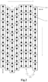
- the antenna apparatus includes an antenna array 100 including M linear array units 110 arranged and spaced apart from each other in a first direction S, in which each linear array unit 110 includes a plurality of radiation units 111 arranged and spaced apart from each other in a second direction T, and N adjacent linear array units 110 in the antenna array 100 are arranged in a staggered manner in the second direction T, where M and N are both integers greater than 1, and N is less than or equal to M.
- a part or all of the linear array units 110 in the antenna array 100 are staggered in the second direction T.
- the regular array surface of the antenna array 100 is changed to an irregular, staggered array surface, and when the antenna beams cover a large angle, more phase granularities (the signal weight of the radiation unit 111 in the linear array unit 110 in the beam forming algorithm) are introduced due to the staggered arrangement of the antenna array surface, to reduce antenna grating lobes during beam scanning at a large angle and increase the coverage of the antenna beams.
- the antenna array is not limited to stagger a part of linear array units 110 in the antenna array 100, but may also include stagger all of the linear array units 110 in the antenna array 100, i.e., causing all the linear array units 110 in the antenna array 100 in a staggered state when N is equal to M.
- the linear array units 110 therein can move any distance in the second direction T, and it works as long as at least two adjacent linear array units 110 therein are changed from a regular arrangement to an irregular arrangement.
- the positions of the staggered linear array units 110 in the antenna array 100 may not be continuous.
- linear array units 110 staggered in the second direction T may include the first three adjacent linear array units 110 and the last two adjacent linear array units 110 in the first direction S.
- the first direction S and the second direction T may be two directions perpendicular to each other, or two directions intersecting at an acute angle.
- the complexity of the antenna apparatus is increased since the regular arrangement manner of the antenna array surface is changed.
- the design of the beamforming circuit will be changed depending on the arrangement of the antenna array surface.
- any two adjacent linear array units 110 are staggered by the same distance in the linear array units 110 of the antenna array 100 arranged in the staggered manner.
- the linear array units 110 in the antenna array 100 are staggered uniformly, i.e., the array surface of the antenna array 100 changes uniformly. Therefore, even after the array surface of the antenna array 100 is changed to an irregular, staggered array surface, the linear array units 110 of the antenna array 100 can still be regular in terms of staggered distance, which is advantageous to the design of the beamforming circuit in the antenna apparatus.
- the design of the beamforming circuit of the antenna apparatus may be made based on different staggered forms.
- N is greater than 2
- the staggered direction of the n th linear array unit 110 relative to the (n-1) th linear array unit 110 is the same as the staggered direction of the (n-1) th linear array unit 110 relative to the (n-2) th linear array unit 110, where n is greater than 2, and n is less than or equal to N.
- the staggered form of the linear array units 110 they can be arranged and staggered in a stepped shape as the 1 st to the 3 rd linear array units 110 from the left in Fig. 1 .
- the staggered direction of the n th linear array unit 110 relative to the (n-1) th linear array unit 110 is opposite to the staggered direction of the (n-1) th linear array unit relative to the (n-2) th linear array unit 110, where n is greater than 2, and n is less than or equal to N.
- they can be arranged and staggered alternately as the 2 nd to the 4 th linear array units 110 from the left in Fig. 1 .
- the vertical surface coverage angle of the communication base station is typically smaller than the horizontal surface coverage angle, and the antenna array 100 therefore can add more radiation units 111 in the vertical direction (i.e., the longitudinal direction) as shown in Fig. 1 .
- the diameter of the antenna array surface in the vertical direction will be increased.
- the linear array units 110 in the antenna array 100 are arranged in the staggered manner, the grating lobes caused by the increased diameter of the antenna array surface can be reduced, thus increasing the coverage of the antenna beams.
- a plurality of radiation units 111 in each linear array unit 110 are spaced equidistantly in the second direction T.
- a staggered distance between any two adjacent linear array units 110 is equal to a distance between two adjacent radiation units 1111 in the linear array unit 110.
- 8 columns of antenna arrays 100 as shown in Fig. 1 are taken here as an example.
- Each linear array unit 110 is a column in Fig. 1 .
- Six radiation units 111 in each linear array unit 110 are spaced equidistantly. The distance between two adjacent radiation units 111 in each linear array unit 110 is a unit of interval.
- the second linear array unit 110 from the left side moves downwards by a unit of interval relative to the first linear array unit 110
- the third linear array unit 110 moves downwards by two units of interval relative to the first linear array unit 110
- the fourth linear array unit 110 moves downwards by a unit of interval relative to the first linear array unit 110.
- each linear array unit 110 still contains radiation units 111 in the same transverse direction. This means that the staggered arrangement of a plurality of linear array units 110 in the transverse direction is still regular, which is advantageous to the design of the beamforming circuit in the antenna apparatus.
- the boundary of the antenna array 100 may be broken. That is, as shown in Fig. 2 , when the second to the fourth linear array units 110 from the left side are staggered in the second direction T (i.e., the longitudinal direction as shown in Fig. 2 ), the boundary of the antenna array 100 is broken at the upper side of the second to the fourth linear array units 110.
- the antenna apparatus may further include at least one virtual radiation unit 200 that is radiation unit(s) 111 not connected to the antenna feed network.
- the virtual radiation unit 200 is disposed adjacent to the radiation unit 111, outermost in the second direction T, of the linear array units 110 arranged in the staggered manner, and the virtual radiation unit 200 and the linear array unit 110 are arranged sequentially in the second direction T.
- the virtual radiation unit 200 and the linear array unit 110 may be arranged sequentially in the second direction T (i.e., the virtual radiation unit 200 arranged at the upper side of the second to the fourth linear radiation units 110 from the left as shown in Fig. 1 or 2 ).
- the number of virtual radiation units 200 correspond to the movement distance of the linear array unit 110
- a unit of interval corresponds to a virtual radiation unit 200.
- the antenna apparatus may also include a beamforming circuit corresponding to the antenna array surface.
- the beamforming circuit includes a plurality of beamforming chips 300 each including X transmission ports (not shown), where each transport port is connected to a power divider 400 via a transmission line 310, and each power divider 400 is configured to feed Y radiation units 111 in one of the linear array units 110 of the antenna array 100, in which X and Y are both integers greater than or equal to 1, Y is less than a number of the plurality of radiation units 111 in each linear array unit 110, and a product of X, Y and the number of the plurality of beamforming chips 300 is equal to a total number of the radiation units 111 in the antenna array 100.
- the beamforming chip 300 is integrated with a shifter circuit and a millimeter wave transceiver front-end circuit.
- the beamforming circuit can adjust, via the power divider 400, a phase and an amplitude of a signal transmitted by a radiation unit 111 in the antenna array 100, and the shifter can adjust a downtilt angle of the antenna apparatus.
- the plurality of beamforming chips 300 are arranged in a matrix shape in the first direction S and the second direction T. In a plurality of rows of beamforming chips 300 arranged in the first direction S, at least two adjacent rows of beamforming chips 300 are staggered in the second direction T, and the staggered distance between two adjacent beamforming chips 300 in the first direction S is the same as the staggered distance between any two adjacent linear array units 110.
- beamforming chips 300 arranged in a staggered manner can be designed based on the staggered array surface of the antenna array 100, guaranteeing that a circuit of each beamforming chip 300 is located in a center position of a plane where a plurality of radiation units 111 fed via respective power dividers 400 are located, to ensure that the beamforming circuit has a low design complexity after the array surface of the antenna array 100 is arranged in the staggered manner.
- An integration design concept is employed for the antenna array surface and the beamforming circuit, and a staggered arrangement solution of the beamforming circuit is taken into consideration when arranging the array surface of the antenna array 100 in the staggered manner, to ensure that the beamforming system has a low design complexity.
- beamforming chips 300 of an integrated design can ensure that the beamforming circuit has a high integration degree.
- the radiation unit 111 in the antenna array 100 may be in the form of a radiation patch, and a parasitic patch may also be added to the radiation unit 111 to increase the impedance bandwidth of the radiation unit 111.
- the radiation unit 111 in addition to the form of patch, may also be a slot antenna, a cavity-backed patch antenna, a cavity-backed slot antenna, or other plane antenna.
- the radiation unit 111 may use coupling feeding, i.e., the antenna apparatus may further include a dielectric substrate 600 on which a plurality of coupling slots 610 one-to-one corresponding to a plurality of radiation units 111 in each linear array unit 110, where each power divider 400 feeds, via a coupling slot 610, a respective radiation unit 111 corresponding to the coupling slot 610.
- Each coupling slot 610 may be of an I-shape. With the I-shaped coupling slot 610, the impedance bandwidth of the antenna can be broadened.
- the coupling slot 610 can be arranged in the 45-degree direction in Fig. 3 , to implement polarization of the radiation unit 111 in the 45-degree direction in Fig. 3 . It is to be understood that the radiation unit 111 may also use coaxial feeding.
- the staggered beamforming circuits of the antenna apparatus may be integrated on a circuit board.
- X being 4, and Y being 3, the structure of the beamforming circuit in the antenna apparatus as shown in Fig. 3 is described.
- each beamforming chip 300 is integrated with four shifter circuits and a millimeter wave transceiver front-end circuit, four paths of front end circuit pins of each beamforming chip 300 fan out via four transmission lines 310, the fan-out transmission lines 310 and the beamforming chip 300 are all located at the circuit board bottom layer, a tip of each transmission line 310 is connected through a signal via 320 upwards to a 1-into-3 power divider 400 which is of a design with equal power and equal phase, to ensure that each path of shifter and the transceiver front-end circuit drive three radiation units 111 arranged vertically, and an output port of each 1-into-3 power divider 400 passes through the coupling slot 610 to feed the feeding unit 111.
- the circuit board may be formed by laminating two sheets of completely symmetrical multi-sheet hybrid plates, where the staggered antenna array surface may be arranged on the top hybrid plate of the circuit board, and the beamforming circuits and the power dividing network may be arranged on the bottom hybrid plate of the circuit board.
- the antenna apparatus may further include a plurality of electrical branches 500, where each electrical branch 500 is connected to the two beamforming chips 300 adjacent in the first direction S, and the electrical branch 500 outermost in the second direction T is arranged in a bent form.
- the middle electrical branches 500 in the second direction T are still of a flat structure (i.e., a linear structure), to thus reduce the impact on the antenna transmission bandwidth and flatness.
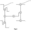
- Fig. 4 illustrates a structure of a 1-into-4 power dividing network.
- Two beamforming chips 300 adjacent in the first direction S are connected via the electrical branch 500 in Fig. 4 . If the two beamforming chips 300 adjacent in the first direction S are in the same transverse direction, they may be connected via a straight electrical branch 500; if the two beamforming chips 300 adjacent in the first direction S are in different transverse directions, they may be connected via a bent electrical branch 500 (as shown in Fig. 1 ).
- the 1-into-4 power dividing network in Fig. 4 further includes a power divider 400 for processing signals.
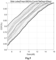
- Fig. 5 illustrates a comparison graph of simulation results of an antenna apparatus provided by some embodiments of the present disclosure and an antenna apparatus with a regular arrangement.
- the abscissa represents an antenna gain measured in dB (decibel), and the ordinate represents a Cumulative Distribution Function.
- the gain when CDF is 1 is a gating lobe size at the maximum scanning angle of the antenna.
- the top curve indicates a grating lobe size at a maximum scanning angle of an antenna apparatus in a staggered arrangement form, while the bottom curve shows a grating lobe size at a maximum scanning angle of an antenna apparatus in a regular arrangement form.
- the antenna apparatus in the staggered arrangement has a maximum grating lobe of 11dB while the antenna apparatus in the regular arrangement has a maximum grating lobe of 16dB; as compared to the antenna apparatus in the regular arrangement, the antenna apparatus in the staggered arrangement optimizes the grating lobe at the maximum scanning angle by 5dB.
- Some embodiments of the present disclosure further provide a base station antenna including the antenna apparatus as described in the above embodiments, where linear array units 110 of the antenna array 100 are arranged in a staggered manner. In this way, a number of radiation units 111 can be increased in the second direction T, to effectively reduce the grating lobes during scanning of antenna beams at a large angle and enlarge the coverage of the antenna beams while improving the EIRP of the antenna.
Landscapes
- Engineering & Computer Science (AREA)
- Computer Networks & Wireless Communication (AREA)
- Variable-Direction Aerials And Aerial Arrays (AREA)
Abstract
Description
- This application is filed based on and claims priority to a
Chinese patent application No. 202110751219.5 filed on July 2, 2021 - Embodiments of the present disclosure relate to the field of wireless communication technology, and specifically to an antenna apparatus and a base station antenna.
- In the high-frequency base station AAU (Active Antenna Unit) active antenna system, as there is a great loss in millimeter wave band path, the beamforming technology is required to enable the antenna to attain a high directional gain. Different from the mid- and low-frequency fully digital beamforming, 5G high frequency mainly adopts the beamforming circuit with digital-analog hybrid architecture, where the analogue shifter behind the antenna element is used to adjust the phase of the element for beamforming.
- In the base station antenna, the EIRP (equivalent isotropically radiated power) can be boosted by increasing the transmit power of the beamforming circuit, or enlarging the antenna array surface, to thus improve the communication system performance. Due to the low output power of the high-frequency single-channel power amplifier in the antenna beamforming circuit, the method of enlarging the antenna array surface is typically employed to improve the EIRP. However, as the diameter of the antenna array is increased, the antenna beam width is inevitably decreased, and the grating lobes of the large-angle beams are increased, thus leading to shrinkage in antenna beam coverage.
- Some embodiments of the present disclosure provide an antenna apparatus comprising an antenna array, in which the antenna array comprises M linear array units arranged and spaced apart from each other in a first direction, each of the linear array units comprises a plurality of radiation units arranged and spaced apart from each other in a second direction, and N of the linear array units adjacent in the antenna array are arranged in a staggered manner in the second direction, where the M and the N are both integers greater than 1, and the N is less than or equal to the M.
- Some embodiments of the present disclosure provide a base station antenna, comprising the antenna apparatus as described above.
-
-
Fig. 1 illustrates a schematic diagram of a staggered structure of an antenna apparatus provided by some embodiments of the present disclosure; -
Fig. 2 illustrates a schematic diagram of a further staggered structure of an antenna apparatus provided by some embodiments of the present disclosure; -
Fig. 3 illustrates a schematic diagram of a feed control structure of an antenna apparatus provided by some embodiments of the present disclosure; -
Fig. 4 illustrates a schematic diagram of a structure of a 1-into-4 power dividing network in an antenna apparatus provided by some embodiments of the present disclosure; and -
Fig. 5 is a comparison graph of simulation results of an antenna apparatus provided by some embodiments of the present disclosure and an antenna apparatus with a regular arrangement. - The objective, technical solution and advantages of embodiments of the present disclosure will become more apparent, through the following detailed description of embodiments of the present disclosure with reference to the accompanying drawings. It would be appreciated by those skilled in the art that, in the various embodiments of the present disclosure, many technical details are provided to enable readers to better understand the present disclosure. However, even without those technical details and various changes and modifications to the embodiments described below, the technical solution according to the present disclosure could still be implemented. Division of the following embodiments is provided for convenience of description, which should not be construed as any limitation to the specific implementation of the present disclosure, and various embodiments could be combined with, or refer to, one another in the case of no conflict occurring.
- Some embodiments of the present disclosure provide an antenna apparatus. As shown in
Figs. 1 and2 , the antenna apparatus includes anantenna array 100 including Mlinear array units 110 arranged and spaced apart from each other in a first direction S, in which eachlinear array unit 110 includes a plurality ofradiation units 111 arranged and spaced apart from each other in a second direction T, and N adjacentlinear array units 110 in theantenna array 100 are arranged in a staggered manner in the second direction T, where M and N are both integers greater than 1, and N is less than or equal to M. - In an antenna apparatus provided by some embodiments of the present disclosure, a part or all of the
linear array units 110 in theantenna array 100 are staggered in the second direction T. In this way, when the antenna array surface is enlarged to boost the EIRP of the antenna, the regular array surface of theantenna array 100 is changed to an irregular, staggered array surface, and when the antenna beams cover a large angle, more phase granularities (the signal weight of theradiation unit 111 in thelinear array unit 110 in the beam forming algorithm) are introduced due to the staggered arrangement of the antenna array surface, to reduce antenna grating lobes during beam scanning at a large angle and increase the coverage of the antenna beams. - It is worth nothing that such optimization of the antenna array is not limited to stagger a part of
linear array units 110 in theantenna array 100, but may also include stagger all of thelinear array units 110 in theantenna array 100, i.e., causing all thelinear array units 110 in theantenna array 100 in a staggered state when N is equal to M. In addition, when a part of thelinear array units 110 in theantenna array 100 are staggered, thelinear array units 110 therein can move any distance in the second direction T, and it works as long as at least two adjacentlinear array units 110 therein are changed from a regular arrangement to an irregular arrangement. In someantenna arrays 100, the positions of the staggeredlinear array units 110 in theantenna array 100 may not be continuous. For example, in a case where theantenna array 100 includes sixlinear array units 110,linear array units 110 staggered in the second direction T may include the first three adjacentlinear array units 110 and the last two adjacentlinear array units 110 in the first direction S. The first direction S and the second direction T may be two directions perpendicular to each other, or two directions intersecting at an acute angle. - After the array surface of the
antenna array 100 is staggered, the complexity of the antenna apparatus is increased since the regular arrangement manner of the antenna array surface is changed. For example, the design of the beamforming circuit will be changed depending on the arrangement of the antenna array surface. In order not to cause the antenna apparatus too complicated when staggering is performed on the array surface, any two adjacentlinear array units 110 are staggered by the same distance in thelinear array units 110 of theantenna array 100 arranged in the staggered manner. As such, thelinear array units 110 in theantenna array 100 are staggered uniformly, i.e., the array surface of theantenna array 100 changes uniformly. Therefore, even after the array surface of theantenna array 100 is changed to an irregular, staggered array surface, thelinear array units 110 of theantenna array 100 can still be regular in terms of staggered distance, which is advantageous to the design of the beamforming circuit in the antenna apparatus. - In addition, when the
linear array units 110 in theantenna array 100 are staggered, different staggered forms may be employed. Therefore, when arranging the beamforming circuit of the antenna apparatus, the design of the beamforming circuit of the antenna apparatus may be made based on different staggered forms. In some embodiments, when N is greater than 2, in the staggeredlinear array units 110, the staggered direction of the nthlinear array unit 110 relative to the (n-1)thlinear array unit 110 is the same as the staggered direction of the (n-1)thlinear array unit 110 relative to the (n-2)thlinear array unit 110, where n is greater than 2, and n is less than or equal to N. In the staggered form of thelinear array units 110, they can be arranged and staggered in a stepped shape as the 1st to the 3rdlinear array units 110 from the left inFig. 1 . In some other embodiments, when N is greater than 2, in the staggeredlinear array units 110, the staggered direction of the nthlinear array unit 110 relative to the (n-1)thlinear array unit 110 is opposite to the staggered direction of the (n-1)th linear array unit relative to the (n-2)thlinear array unit 110, where n is greater than 2, and n is less than or equal to N. In the staggered form of thelinear array units 110, they can be arranged and staggered alternately as the 2nd to the 4thlinear array units 110 from the left inFig. 1 . - In an actual application, the vertical surface coverage angle of the communication base station is typically smaller than the horizontal surface coverage angle, and the
antenna array 100 therefore can addmore radiation units 111 in the vertical direction (i.e., the longitudinal direction) as shown inFig. 1 . In the case, after theradiation units 111 are added to theantenna array 100 in the vertical direction, the diameter of the antenna array surface in the vertical direction will be increased. Meanwhile, thelinear array units 110 in theantenna array 100 are arranged in the staggered manner, the grating lobes caused by the increased diameter of the antenna array surface can be reduced, thus increasing the coverage of the antenna beams. - As shown in
Fig. 1 , in some embodiments, a plurality ofradiation units 111 in eachlinear array unit 110 are spaced equidistantly in the second direction T. In thelinear array units 110 arranged in the staggered manner in theantenna array 100, a staggered distance between any two adjacentlinear array units 110 is equal to a distance between two adjacent radiation units 1111 in thelinear array unit 110. 8 columns ofantenna arrays 100 as shown inFig. 1 are taken here as an example. Eachlinear array unit 110 is a column inFig. 1 . Sixradiation units 111 in eachlinear array unit 110 are spaced equidistantly. The distance between twoadjacent radiation units 111 in eachlinear array unit 110 is a unit of interval. The secondlinear array unit 110 from the left side moves downwards by a unit of interval relative to the firstlinear array unit 110, the thirdlinear array unit 110 moves downwards by two units of interval relative to the firstlinear array unit 110, and the fourthlinear array unit 110 moves downwards by a unit of interval relative to the firstlinear array unit 110. In this way, although the staggered arrangement is formed on the array surface of theantenna array 100, eachlinear array unit 110 still containsradiation units 111 in the same transverse direction. This means that the staggered arrangement of a plurality oflinear array units 110 in the transverse direction is still regular, which is advantageous to the design of the beamforming circuit in the antenna apparatus. - After the array surface of the
antenna array 100 is arranged in the staggered manner, the boundary of theantenna array 100 may be broken. That is, as shown inFig. 2 , when the second to the fourthlinear array units 110 from the left side are staggered in the second direction T (i.e., the longitudinal direction as shown inFig. 2 ), the boundary of theantenna array 100 is broken at the upper side of the second to the fourthlinear array units 110. In order to ensure the completeness of the boundary of theantenna array 100, the antenna apparatus may further include at least onevirtual radiation unit 200 that is radiation unit(s) 111 not connected to the antenna feed network. Thevirtual radiation unit 200 is disposed adjacent to theradiation unit 111, outermost in the second direction T, of thelinear array units 110 arranged in the staggered manner, and thevirtual radiation unit 200 and thelinear array unit 110 are arranged sequentially in the second direction T. For example, when any one of thelinear array units 110 is staggered by a unit of interval, at least onevirtual radiation unit 200 and thelinear array unit 110 may be arranged sequentially in the second direction T (i.e., thevirtual radiation unit 200 arranged at the upper side of the second to the fourthlinear radiation units 110 from the left as shown inFig. 1 or2 ). At this time, the number ofvirtual radiation units 200 correspond to the movement distance of thelinear array unit 110, and a unit of interval corresponds to avirtual radiation unit 200. - In addition, the antenna apparatus according to some embodiments of the present disclosure may also include a beamforming circuit corresponding to the antenna array surface. As shown in
Figs. 1 and3 , the beamforming circuit includes a plurality ofbeamforming chips 300 each including X transmission ports (not shown), where each transport port is connected to apower divider 400 via atransmission line 310, and eachpower divider 400 is configured to feedY radiation units 111 in one of thelinear array units 110 of theantenna array 100, in which X and Y are both integers greater than or equal to 1, Y is less than a number of the plurality ofradiation units 111 in eachlinear array unit 110, and a product of X, Y and the number of the plurality ofbeamforming chips 300 is equal to a total number of theradiation units 111 in theantenna array 100. Thebeamforming chip 300 is integrated with a shifter circuit and a millimeter wave transceiver front-end circuit. The beamforming circuit can adjust, via thepower divider 400, a phase and an amplitude of a signal transmitted by aradiation unit 111 in theantenna array 100, and the shifter can adjust a downtilt angle of the antenna apparatus. - In some embodiments, the plurality of
beamforming chips 300 are arranged in a matrix shape in the first direction S and the second direction T. In a plurality of rows ofbeamforming chips 300 arranged in the first direction S, at least two adjacent rows ofbeamforming chips 300 are staggered in the second direction T, and the staggered distance between twoadjacent beamforming chips 300 in the first direction S is the same as the staggered distance between any two adjacentlinear array units 110. In this way,beamforming chips 300 arranged in a staggered manner can be designed based on the staggered array surface of theantenna array 100, guaranteeing that a circuit of eachbeamforming chip 300 is located in a center position of a plane where a plurality ofradiation units 111 fed viarespective power dividers 400 are located, to ensure that the beamforming circuit has a low design complexity after the array surface of theantenna array 100 is arranged in the staggered manner. An integration design concept is employed for the antenna array surface and the beamforming circuit, and a staggered arrangement solution of the beamforming circuit is taken into consideration when arranging the array surface of theantenna array 100 in the staggered manner, to ensure that the beamforming system has a low design complexity. Meanwhile,beamforming chips 300 of an integrated design can ensure that the beamforming circuit has a high integration degree. - In some embodiments, the
radiation unit 111 in theantenna array 100 may be in the form of a radiation patch, and a parasitic patch may also be added to theradiation unit 111 to increase the impedance bandwidth of theradiation unit 111. In some other embodiments, in addition to the form of patch, theradiation unit 111 may also be a slot antenna, a cavity-backed patch antenna, a cavity-backed slot antenna, or other plane antenna. - In addition, the
radiation unit 111 may use coupling feeding, i.e., the antenna apparatus may further include adielectric substrate 600 on which a plurality ofcoupling slots 610 one-to-one corresponding to a plurality ofradiation units 111 in eachlinear array unit 110, where eachpower divider 400 feeds, via acoupling slot 610, arespective radiation unit 111 corresponding to thecoupling slot 610. Eachcoupling slot 610 may be of an I-shape. With the I-shapedcoupling slot 610, the impedance bandwidth of the antenna can be broadened. Meanwhile, thecoupling slot 610 can be arranged in the 45-degree direction inFig. 3 , to implement polarization of theradiation unit 111 in the 45-degree direction inFig. 3 . It is to be understood that theradiation unit 111 may also use coaxial feeding. - In some embodiments, the staggered beamforming circuits of the antenna apparatus may be integrated on a circuit board. With X being 4, and Y being 3, the structure of the beamforming circuit in the antenna apparatus as shown in
Fig. 3 is described. Wherein, eachbeamforming chip 300 is integrated with four shifter circuits and a millimeter wave transceiver front-end circuit, four paths of front end circuit pins of eachbeamforming chip 300 fan out via fourtransmission lines 310, the fan-outtransmission lines 310 and thebeamforming chip 300 are all located at the circuit board bottom layer, a tip of eachtransmission line 310 is connected through a signal via 320 upwards to a 1-into-3power divider 400 which is of a design with equal power and equal phase, to ensure that each path of shifter and the transceiver front-end circuit drive threeradiation units 111 arranged vertically, and an output port of each 1-into-3power divider 400 passes through thecoupling slot 610 to feed thefeeding unit 111. In addition, the circuit board may be formed by laminating two sheets of completely symmetrical multi-sheet hybrid plates, where the staggered antenna array surface may be arranged on the top hybrid plate of the circuit board, and the beamforming circuits and the power dividing network may be arranged on the bottom hybrid plate of the circuit board. - Moreover, two
beamforming chips 300 in the antenna apparatus adjacent in the first direction S are connected via the power dividing network. In order to connect the twobeamforming chips 300 adjacent in the first direction S, in some embodiments, the antenna apparatus may further include a plurality ofelectrical branches 500, where eachelectrical branch 500 is connected to the twobeamforming chips 300 adjacent in the first direction S, and theelectrical branch 500 outermost in the second direction T is arranged in a bent form. As such, only theelectrical branch 500 outermost in the second direction T is bent, but the middleelectrical branches 500 in the second direction T are still of a flat structure (i.e., a linear structure), to thus reduce the impact on the antenna transmission bandwidth and flatness.Fig. 4 illustrates a structure of a 1-into-4 power dividing network. Twobeamforming chips 300 adjacent in the first direction S are connected via theelectrical branch 500 inFig. 4 . If the twobeamforming chips 300 adjacent in the first direction S are in the same transverse direction, they may be connected via a straightelectrical branch 500; if the twobeamforming chips 300 adjacent in the first direction S are in different transverse directions, they may be connected via a bent electrical branch 500 (as shown inFig. 1 ). The 1-into-4 power dividing network inFig. 4 further includes apower divider 400 for processing signals. -
Fig. 5 illustrates a comparison graph of simulation results of an antenna apparatus provided by some embodiments of the present disclosure and an antenna apparatus with a regular arrangement. InFig. 5 , the abscissa represents an antenna gain measured in dB (decibel), and the ordinate represents a Cumulative Distribution Function. The gain when CDF is 1 is a gating lobe size at the maximum scanning angle of the antenna. InFig. 5 , the top curve indicates a grating lobe size at a maximum scanning angle of an antenna apparatus in a staggered arrangement form, while the bottom curve shows a grating lobe size at a maximum scanning angle of an antenna apparatus in a regular arrangement form. It can be seen therefrom that the antenna apparatus in the staggered arrangement has a maximum grating lobe of 11dB while the antenna apparatus in the regular arrangement has a maximum grating lobe of 16dB; as compared to the antenna apparatus in the regular arrangement, the antenna apparatus in the staggered arrangement optimizes the grating lobe at the maximum scanning angle by 5dB. - Some embodiments of the present disclosure further provide a base station antenna including the antenna apparatus as described in the above embodiments, where
linear array units 110 of theantenna array 100 are arranged in a staggered manner. In this way, a number ofradiation units 111 can be increased in the second direction T, to effectively reduce the grating lobes during scanning of antenna beams at a large angle and enlarge the coverage of the antenna beams while improving the EIRP of the antenna. - It would be understood by the ordinary skilled in the art that the implementations as described above are only specific embodiments of the present disclosure, and in actual application, various variations may be allowed with respect to form and detail, without departing spirits and scope of the present disclosure.
Claims (11)
- An antenna apparatus, comprising:
an antenna array (100) comprising M linear array units (110) arranged and spaced apart from each other in a first direction, each of the linear array units (110) comprising a plurality of radiation units (111) arranged and spaced apart from each other in a second direction, N of the linear array units (110) adjacent in the antenna array (100) being arranged in a staggered manner in the second direction, where the M and the N are both integers greater than 1, and the N is less than or equal to the M. - The antenna apparatus of claim 1, wherein:
in the linear array units (110) arranged in the staggered manner, a staggered distance between any two of the linear array units (110) adjacent is the same. - The antenna apparatus of claim 1 or 2, wherein:
the N is greater than 2, and a staggered direction of an nth linear array unit (110) in the linear array units (110) arranged in the staggered manner relative to an (n-1)th linear array unit (110) is the same as a staggered direction of the (n-1)th linear array unit (110) relative to an (n-2)th linear array unit (110), where n is greater than 2, and n is less than or equal to the N. - The antenna apparatus of claim 1 or 2, wherein:
the N is greater than 2, and a staggered direction of an nth linear array unit (110) in the linear array units (110) arranged in the staggered manner relative to an (n-1)th linear array unit (110) is opposite to a staggered direction of the (n-1)th linear array unit (110) relative to an (n-2)th linear array unit (110), where n is greater than 2, and n is less than or equal to the N. - The antenna apparatus of claim 2, wherein:
the plurality of radiation units (111) in each of the linear array units (110) are spaced equidistantly in the second direction, and a staggered distance between any two of the linear array units (110) adjacent in the linear array units (110) arranged in the staggered manner is equal to a distance between two of the radiation units (111) adjacent in each of the linear array units (110). - The antenna apparatus of claim 1, further comprising:
at least one virtual radiation unit (200), the at least one virtual radiation unit (200) being arranged adjacent to the radiation unit (111), outermost in the second direction, of the linear array units (110) arranged in the staggered manner, the at least one virtual radiation unit (200) and the linear array units (110) being arranged sequentially in the second direction. - The antenna apparatus of claim 1, further comprising:
a plurality of beamforming chips (300), each of the beamforming chips (300) having X transmission ports, each of the transmission ports being connected with a power divider (400), each power divider (400) being configured to feed Y of the radiation units (111) in one of the linear array units (110), wherein the X and the Y are both an integer greater than or equal to 1, the Y is less than or equal to a number of the plurality of radiation units (111) in each of the linear array units (110), and a product of the X, the Y and a number of the plurality of beamforming chips (300) is equal to a number of the radiation units (111) in the antenna array (100). - The antenna apparatus of claim 7, wherein:
the plurality of beamforming chips (300) are arranged in a matrix shape in the first direction and the second direction, at least two adjacent rows of the beamforming chips (300) in a plurality of rows of the beamforming chips (300) arranged in the first direction are staggered arranged in the second direction, and a staggered distance between two rows of the beamforming chips (300) adjacent in the first direction is the same as a staggered distance between any two of the linear array units (110) adjacent. - The antenna apparatus of claim 8, further comprising:
a plurality of electrical branches (500), each of the electrical branches (500) being connected to two of the beamforming chips (300) adjacent in the first direction, and the electrical branch (500) outermost in the second direction being arranged in a bent form. - The antenna apparatus of claim 7, further comprising:
a dielectric substrate (600), a plurality of coupling slots (610) one-to-one corresponding to the plurality of radiation units (111) in each of the linear array units (110) being arranged on the dielectric substrate (600), each power divider (400) feeding, via the coupling slot (610), the radiation unit (111) corresponding to the coupling slot (610). - Abase station antenna, comprising:
the antenna apparatus of any one of claims 1-10.
Applications Claiming Priority (2)
| Application Number | Priority Date | Filing Date | Title |
|---|---|---|---|
| CN202110751219.5A CN115566441A (en) | 2021-07-02 | 2021-07-02 | Antenna device and base station antenna |
| PCT/CN2022/101579 WO2023274159A1 (en) | 2021-07-02 | 2022-06-27 | Antenna apparatus and base station antenna |
Publications (2)
| Publication Number | Publication Date |
|---|---|
| EP4366089A1 true EP4366089A1 (en) | 2024-05-08 |
| EP4366089A4 EP4366089A4 (en) | 2024-11-13 |
Family
ID=84690104
Family Applications (1)
| Application Number | Title | Priority Date | Filing Date |
|---|---|---|---|
| EP22831973.7A Pending EP4366089A4 (en) | 2021-07-02 | 2022-06-27 | Antenna apparatus and base station antenna |
Country Status (6)
| Country | Link |
|---|---|
| US (1) | US12506254B2 (en) |
| EP (1) | EP4366089A4 (en) |
| JP (1) | JP2024522927A (en) |
| KR (1) | KR102932739B1 (en) |
| CN (1) | CN115566441A (en) |
| WO (1) | WO2023274159A1 (en) |
Families Citing this family (1)
| Publication number | Priority date | Publication date | Assignee | Title |
|---|---|---|---|---|
| KR102872089B1 (en) * | 2024-07-25 | 2025-10-17 | 한화엔엑스엠디 주식회사 | Array Antenna For Reducing Grating Lone and Cross Polarization Leakage |
Family Cites Families (16)
| Publication number | Priority date | Publication date | Assignee | Title |
|---|---|---|---|---|
| SE9603565D0 (en) | 1996-05-13 | 1996-09-30 | Allgon Ab | Flat antenna |
| US5923289A (en) * | 1997-07-28 | 1999-07-13 | Motorola, Inc. | Modular array and phased array antenna system |
| JP3279264B2 (en) * | 1998-09-04 | 2002-04-30 | 三菱電機株式会社 | Microstrip array antenna |
| US6583760B2 (en) * | 1998-12-17 | 2003-06-24 | Metawave Communications Corporation | Dual mode switched beam antenna |
| US6198434B1 (en) * | 1998-12-17 | 2001-03-06 | Metawave Communications Corporation | Dual mode switched beam antenna |
| EP2165388B1 (en) * | 2007-06-13 | 2018-01-17 | Intel Corporation | Triple stagger offsetable azimuth beam width controlled antenna for wireless network |
| JP2010200166A (en) * | 2009-02-26 | 2010-09-09 | Toshiba Corp | Array antenna |
| CN107431278A (en) * | 2015-12-22 | 2017-12-01 | 华为技术有限公司 | Communication device and wireless communication equipment |
| CN105742828B (en) * | 2016-03-31 | 2018-09-28 | 广东通宇通讯股份有限公司 | Dual-polarized three-beam antenna and feed network device thereof |
| CN206003971U (en) * | 2016-09-22 | 2017-03-08 | 京信通信技术(广州)有限公司 | Wave-packet shaping network and its input structure, three beam antennas |
| WO2019116970A1 (en) * | 2017-12-12 | 2019-06-20 | 株式会社村田製作所 | High-frequency module and communication device |
| JP2020085529A (en) * | 2018-11-19 | 2020-06-04 | 株式会社デンソー | Radar apparatus |
| JP7573926B2 (en) * | 2019-03-20 | 2024-10-28 | パナソニックオートモーティブシステムズ株式会社 | Radar device and transmitting/receiving array antenna |
| CN112133999B (en) * | 2019-06-24 | 2025-03-25 | 户外无线网络有限公司 | Base station antenna |
| CN110943295B (en) * | 2019-11-25 | 2021-08-03 | 中信科移动通信技术股份有限公司 | Multi-beam antenna array, base station antenna and antenna array decoupling method |
| CN116325364B (en) | 2020-09-28 | 2026-03-20 | 华为技术有限公司 | An antenna array, device, and wireless communication equipment |
-
2021
- 2021-07-02 CN CN202110751219.5A patent/CN115566441A/en active Pending
-
2022
- 2022-06-27 JP JP2023580905A patent/JP2024522927A/en active Pending
- 2022-06-27 WO PCT/CN2022/101579 patent/WO2023274159A1/en not_active Ceased
- 2022-06-27 KR KR1020247002600A patent/KR102932739B1/en active Active
- 2022-06-27 EP EP22831973.7A patent/EP4366089A4/en active Pending
-
2024
- 2024-01-02 US US18/402,555 patent/US12506254B2/en active Active
Also Published As
| Publication number | Publication date |
|---|---|
| US20240136704A1 (en) | 2024-04-25 |
| EP4366089A4 (en) | 2024-11-13 |
| KR102932739B1 (en) | 2026-02-27 |
| WO2023274159A1 (en) | 2023-01-05 |
| JP2024522927A (en) | 2024-06-21 |
| CN115566441A (en) | 2023-01-03 |
| US20240235011A9 (en) | 2024-07-11 |
| US12506254B2 (en) | 2025-12-23 |
| KR20240028441A (en) | 2024-03-05 |
Similar Documents
| Publication | Publication Date | Title |
|---|---|---|
| CN102859789B (en) | Antenna arrays, antenna assemblies and base stations | |
| CN109716589B (en) | An antenna array and communication equipment | |
| US9397740B2 (en) | Modular antenna array with RF and baseband beamforming | |
| US20200006864A1 (en) | Antenna module and communication apparatus | |
| KR101937820B1 (en) | Multi-beam array antenna | |
| CN112436277A (en) | Array antenna | |
| US12294141B2 (en) | Antenna calibration boards having non-uniform coupler sections | |
| CN102971906A (en) | Modular phased array antenna | |
| US20230291121A1 (en) | Base station antennas having calibration circuit connections that provide improved in-column and/or adjacent cross-column isolation | |
| CN108666769B (en) | A broadband nine-beam array antenna | |
| US12506254B2 (en) | Antenna apparatus and base station antenna | |
| WO2021000476A1 (en) | Multi-frequency narrow beam antenna | |
| US10700444B2 (en) | Multi-beam phased antenna structure and controlling method thereof | |
| CN108258422B (en) | Antenna array based on passive decoupling technology | |
| CN107681270B (en) | Base station antenna and beam shaping method thereof | |
| JPWO2017090200A1 (en) | Antenna device | |
| CN212062682U (en) | Microstrip antenna | |
| WO2019084671A1 (en) | Antenna array with abfn circuitry | |
| WO2022062472A1 (en) | Active array antenna and mobile communication base station | |
| CN108550990B (en) | 5G large-scale antenna beam control system and method | |
| US11728575B1 (en) | VICTS antenna based on RGW structure | |
| US20230395974A1 (en) | Mixed element beam forming antenna | |
| CN218101693U (en) | A Dual Polarized Microstrip Phased Array Antenna | |
| CN108767494A (en) | A kind of dual polarization rectangle figuration venue thinned array antenna | |
| TWI674704B (en) | Low sidelobe array antenna |
Legal Events
| Date | Code | Title | Description |
|---|---|---|---|
| STAA | Information on the status of an ep patent application or granted ep patent |
Free format text: STATUS: THE INTERNATIONAL PUBLICATION HAS BEEN MADE |
|
| PUAI | Public reference made under article 153(3) epc to a published international application that has entered the european phase |
Free format text: ORIGINAL CODE: 0009012 |
|
| STAA | Information on the status of an ep patent application or granted ep patent |
Free format text: STATUS: REQUEST FOR EXAMINATION WAS MADE |
|
| 17P | Request for examination filed |
Effective date: 20240125 |
|
| AK | Designated contracting states |
Kind code of ref document: A1 Designated state(s): AL AT BE BG CH CY CZ DE DK EE ES FI FR GB GR HR HU IE IS IT LI LT LU LV MC MK MT NL NO PL PT RO RS SE SI SK SM TR |
|
| DAV | Request for validation of the european patent (deleted) | ||
| DAX | Request for extension of the european patent (deleted) | ||
| A4 | Supplementary search report drawn up and despatched |
Effective date: 20241010 |
|
| RIC1 | Information provided on ipc code assigned before grant |
Ipc: H01Q 21/08 20060101ALI20241004BHEP Ipc: H01Q 21/06 20060101ALI20241004BHEP Ipc: H01Q 3/40 20060101ALI20241004BHEP Ipc: H01Q 1/24 20060101ALI20241004BHEP Ipc: H01Q 3/26 20060101ALI20241004BHEP Ipc: H01Q 21/00 20060101AFI20241004BHEP |