EP4365915A2 - Variabler brennstabdurchmesser - Google Patents
Variabler brennstabdurchmesser Download PDFInfo
- Publication number
- EP4365915A2 EP4365915A2 EP24158749.2A EP24158749A EP4365915A2 EP 4365915 A2 EP4365915 A2 EP 4365915A2 EP 24158749 A EP24158749 A EP 24158749A EP 4365915 A2 EP4365915 A2 EP 4365915A2
- Authority
- EP
- European Patent Office
- Prior art keywords
- diameter
- axial
- region
- fuel
- fuel rod
- Prior art date
- Legal status (The legal status is an assumption and is not a legal conclusion. Google has not performed a legal analysis and makes no representation as to the accuracy of the status listed.)
- Pending
Links
- 239000000446 fuel Substances 0.000 title claims abstract description 229
- 238000005253 cladding Methods 0.000 claims abstract description 84
- 239000008188 pellet Substances 0.000 claims abstract description 45
- 239000000463 material Substances 0.000 claims abstract description 15
- 238000012886 linear function Methods 0.000 claims description 4
- 229910001093 Zr alloy Inorganic materials 0.000 claims description 3
- 239000011800 void material Substances 0.000 description 15
- 230000006870 function Effects 0.000 description 8
- 238000004519 manufacturing process Methods 0.000 description 7
- 230000009257 reactivity Effects 0.000 description 7
- 239000006096 absorbing agent Substances 0.000 description 6
- 239000000203 mixture Substances 0.000 description 6
- 230000004048 modification Effects 0.000 description 6
- 238000012986 modification Methods 0.000 description 6
- 230000008901 benefit Effects 0.000 description 5
- 239000002826 coolant Substances 0.000 description 5
- 239000007789 gas Substances 0.000 description 5
- 239000002574 poison Substances 0.000 description 4
- 231100000614 poison Toxicity 0.000 description 4
- 239000007787 solid Substances 0.000 description 4
- 230000000712 assembly Effects 0.000 description 3
- 238000000429 assembly Methods 0.000 description 3
- 238000010276 construction Methods 0.000 description 3
- 230000004992 fission Effects 0.000 description 3
- 230000014509 gene expression Effects 0.000 description 3
- 238000000034 method Methods 0.000 description 3
- 239000004449 solid propellant Substances 0.000 description 3
- 230000007704 transition Effects 0.000 description 3
- XLYOFNOQVPJJNP-UHFFFAOYSA-N water Substances O XLYOFNOQVPJJNP-UHFFFAOYSA-N 0.000 description 3
- ZOXJGFHDIHLPTG-UHFFFAOYSA-N Boron Chemical compound [B] ZOXJGFHDIHLPTG-UHFFFAOYSA-N 0.000 description 2
- 229910052796 boron Inorganic materials 0.000 description 2
- 238000006243 chemical reaction Methods 0.000 description 2
- 239000000306 component Substances 0.000 description 2
- 239000000470 constituent Substances 0.000 description 2
- 238000013461 design Methods 0.000 description 2
- 239000004615 ingredient Substances 0.000 description 2
- 239000010410 layer Substances 0.000 description 2
- OOAWCECZEHPMBX-UHFFFAOYSA-N oxygen(2-);uranium(4+) Chemical compound [O-2].[O-2].[U+4] OOAWCECZEHPMBX-UHFFFAOYSA-N 0.000 description 2
- UTDLAEPMVCFGRJ-UHFFFAOYSA-N plutonium dihydrate Chemical compound O.O.[Pu] UTDLAEPMVCFGRJ-UHFFFAOYSA-N 0.000 description 2
- FLDALJIYKQCYHH-UHFFFAOYSA-N plutonium(IV) oxide Inorganic materials [O-2].[O-2].[Pu+4] FLDALJIYKQCYHH-UHFFFAOYSA-N 0.000 description 2
- RCKBMGHMPOIFND-UHFFFAOYSA-N sulfanylidene(sulfanylidenegallanylsulfanyl)gallane Chemical compound S=[Ga]S[Ga]=S RCKBMGHMPOIFND-UHFFFAOYSA-N 0.000 description 2
- FCTBKIHDJGHPPO-UHFFFAOYSA-N uranium dioxide Inorganic materials O=[U]=O FCTBKIHDJGHPPO-UHFFFAOYSA-N 0.000 description 2
- 229910052691 Erbium Inorganic materials 0.000 description 1
- 229910052688 Gadolinium Inorganic materials 0.000 description 1
- 229910052772 Samarium Inorganic materials 0.000 description 1
- 229910007948 ZrB2 Inorganic materials 0.000 description 1
- 238000010521 absorption reaction Methods 0.000 description 1
- VWZIXVXBCBBRGP-UHFFFAOYSA-N boron;zirconium Chemical compound B#[Zr]#B VWZIXVXBCBBRGP-UHFFFAOYSA-N 0.000 description 1
- 229910052793 cadmium Inorganic materials 0.000 description 1
- BDOSMKKIYDKNTQ-UHFFFAOYSA-N cadmium atom Chemical compound [Cd] BDOSMKKIYDKNTQ-UHFFFAOYSA-N 0.000 description 1
- 238000004364 calculation method Methods 0.000 description 1
- 239000011247 coating layer Substances 0.000 description 1
- UYAHIZSMUZPPFV-UHFFFAOYSA-N erbium Chemical compound [Er] UYAHIZSMUZPPFV-UHFFFAOYSA-N 0.000 description 1
- 150000002178 europium compounds Chemical class 0.000 description 1
- 230000004907 flux Effects 0.000 description 1
- UIWYJDYFSGRHKR-UHFFFAOYSA-N gadolinium atom Chemical compound [Gd] UIWYJDYFSGRHKR-UHFFFAOYSA-N 0.000 description 1
- 239000001307 helium Substances 0.000 description 1
- 229910052734 helium Inorganic materials 0.000 description 1
- SWQJXJOGLNCZEY-UHFFFAOYSA-N helium atom Chemical compound [He] SWQJXJOGLNCZEY-UHFFFAOYSA-N 0.000 description 1
- 238000000691 measurement method Methods 0.000 description 1
- 239000003607 modifier Substances 0.000 description 1
- 210000002569 neuron Anatomy 0.000 description 1
- 239000003758 nuclear fuel Substances 0.000 description 1
- 230000008520 organization Effects 0.000 description 1
- 239000002245 particle Substances 0.000 description 1
- 238000012552 review Methods 0.000 description 1
- KZUNJOHGWZRPMI-UHFFFAOYSA-N samarium atom Chemical compound [Sm] KZUNJOHGWZRPMI-UHFFFAOYSA-N 0.000 description 1
- 238000006467 substitution reaction Methods 0.000 description 1
- 230000000153 supplemental effect Effects 0.000 description 1
- 230000009466 transformation Effects 0.000 description 1
Images





Classifications
-
- G—PHYSICS
- G21—NUCLEAR PHYSICS; NUCLEAR ENGINEERING
- G21C—NUCLEAR REACTORS
- G21C3/00—Reactor fuel elements and their assemblies; Selection of substances for use as reactor fuel elements
- G21C3/02—Fuel elements
- G21C3/04—Constructional details
-
- G—PHYSICS
- G21—NUCLEAR PHYSICS; NUCLEAR ENGINEERING
- G21C—NUCLEAR REACTORS
- G21C3/00—Reactor fuel elements and their assemblies; Selection of substances for use as reactor fuel elements
- G21C3/02—Fuel elements
- G21C3/04—Constructional details
- G21C3/06—Casings; Jackets
-
- G—PHYSICS
- G21—NUCLEAR PHYSICS; NUCLEAR ENGINEERING
- G21C—NUCLEAR REACTORS
- G21C3/00—Reactor fuel elements and their assemblies; Selection of substances for use as reactor fuel elements
- G21C3/02—Fuel elements
- G21C3/04—Constructional details
- G21C3/16—Details of the construction within the casing
- G21C3/17—Means for storage or immobilisation of gases in fuel elements
-
- G—PHYSICS
- G21—NUCLEAR PHYSICS; NUCLEAR ENGINEERING
- G21C—NUCLEAR REACTORS
- G21C3/00—Reactor fuel elements and their assemblies; Selection of substances for use as reactor fuel elements
- G21C3/30—Assemblies of a number of fuel elements in the form of a rigid unit
- G21C3/32—Bundles of parallel pin-, rod-, or tube-shaped fuel elements
- G21C3/3213—Means for the storage or removal of fission gases
-
- G—PHYSICS
- G21—NUCLEAR PHYSICS; NUCLEAR ENGINEERING
- G21C—NUCLEAR REACTORS
- G21C7/00—Control of nuclear reaction
- G21C7/02—Control of nuclear reaction by using self-regulating properties of reactor materials, e.g. Doppler effect
- G21C7/04—Control of nuclear reaction by using self-regulating properties of reactor materials, e.g. Doppler effect of burnable poisons
-
- G—PHYSICS
- G21—NUCLEAR PHYSICS; NUCLEAR ENGINEERING
- G21C—NUCLEAR REACTORS
- G21C7/00—Control of nuclear reaction
- G21C7/28—Control of nuclear reaction by displacement of the reflector or parts thereof
-
- Y—GENERAL TAGGING OF NEW TECHNOLOGICAL DEVELOPMENTS; GENERAL TAGGING OF CROSS-SECTIONAL TECHNOLOGIES SPANNING OVER SEVERAL SECTIONS OF THE IPC; TECHNICAL SUBJECTS COVERED BY FORMER USPC CROSS-REFERENCE ART COLLECTIONS [XRACs] AND DIGESTS
- Y02—TECHNOLOGIES OR APPLICATIONS FOR MITIGATION OR ADAPTATION AGAINST CLIMATE CHANGE
- Y02E—REDUCTION OF GREENHOUSE GAS [GHG] EMISSIONS, RELATED TO ENERGY GENERATION, TRANSMISSION OR DISTRIBUTION
- Y02E30/00—Energy generation of nuclear origin
- Y02E30/30—Nuclear fission reactors
Definitions
- the reactor core includes a large number of fuel assemblies, each of which is composed of a plurality of elongated fuel elements or rods.
- the fuel rods each contain fissile material such as uranium dioxide (UO2) or plutonium dioxide (PuO2), or mixtures of these, usually in the form of a stack of nuclear fuel pellets, although annular or particle forms of fuel also are used.
- the fuel rods are grouped together in an array which is organized to provide a neutron flux in the core sufficient to support a high rate of nuclear fission and thus the release of a large amount of energy in the form of heat.
- a coolant, such as water, is pumped through the core in order to extract some of the heat generated in the core for the production of useful work.
- Fuel assemblies vary in size and design depending on the desired size of the core and the size of the reactor.
- a fissile material may produce an excess amount of neutrons during this stage of the fission reaction.
- the reactivity of the fissile material declines after the initial operation and can result in variable reactivity over the lifetime of the reactor. A more desirable results is a constant reactivity over the lifetime of the reactor.
- Various methods may be used to counteract or absorb the initial excess reactivity of the fissile material.
- control rods are inserted into the reactor cores to absorb the excess neutrons.
- the fuel composition may be tailored for constant reactivity or to attain certain burnup levels.
- control rods and fuel compositions use a neutron absorber, known in the art as "burnable poisons” or “burnable absorbers”, and may include, boron, gadolinium, cadmium, samarium, erbium and europium compounds.
- Burnable poisons absorb the initial excess amount of neutrons while, ideally, producing no new or additional neutrons or changing into new neutron poisons as a result of neutron absorption. During the early stages of operation of such a fuel element, excess neutrons are absorbed by the burnable poison, which preferably undergoes transformation to elements having a low number of neutrons.
- the fuel pellets may be coated in a thin external layer of zirconium diboride (ZrB 2 ) or a similar material creating an integral fuel burnable absorber (IFBA).
- the boron in a ZrB 2 IFBA coated fuel pellets may react with the fissile material and produce helium gas.
- the production of gas within the fuel rod can be problematic because the fuel rod is a sealed housing.
- the production of gas increases the internal pressure of the fuel rod (known as RIP).
- the fission reaction itself produces gases that contribute to the increase of the internal pressure of the fuel rod.
- the internal pressure of the fuel rod must stay under certain levels so that the pressure does not compromise the structural integrity of the fuel rod. This creates a tradeoff between safe operating the fuel rod internal pressure, higher burnup fuel compositions, and IFBA materials to absorb excess neutrons. Therefore the internal pressure of the fuel rod acts as a limiting factor against increasing fuel burnup level, extending fuel lifetime, or maintaining constant reactivity.
- variable diameter fuel rod of a nuclear reactor assembly comprises an elongated cladding tube configured to house a plurality of fuel pellets comprising a fissile material arranged in a fuel stack orientation; the elongated cladding tube comprising first and second axial reflector regions, and a middle axial region therebetween; an outer cladding diameter of the middle axial region defined as d 1 ; and an outer cladding diameter of at least one of the first or second axial reflector regions defined as d 2 ; wherein the diameter d 2 of the axial reflector region is greater than the diameter d 1 of the middle axial region; and a transitional region between the second diameter d 1 of the middle axial region and the larger diameter d 2 of the axial reflector region.
- the present disclosure provides a fuel rod assembly.
- the fuel rod assembly comprises a plurality of control rods comprising a plurality burnable absorbers; a plurality of fuel rods comprising an elongated cladding tube housing a plurality of fuel pellets, wherein the fuel pellets comprise a fissile material, and wherein the fuel pellets are arranged in a fuel stack orientation; the plurality of fuel rods comprising: one or more constant diameter fuel rods and one or more variable diameter fuel rods, wherein the variable diameter fuel rods comprise a middle axial region located between an first axial reflector region and a second axial reflector region; the middle axial region has an outer diameter, d 1 ; the first axial reflector region has an outer diameter, d 2 ; the second axial reflector region has an outer diameter, ds, wherein d 2 or d 3 is greater than d 1 ; and a transitional region between the middle axial reflector region and a larger diameter axial reflector region is defined by a
- Limitations associated with the internal pressure of the fuel rod may be resolved by increasing the internal void volume of the fuel rod. In certain aspects, this may result in a decrease in the internal pressure of the fuel rod or may optimize the energy output of the fuel rod. Increasing the internal void volume for a fuel rod provides greater flexibility for designing a reactor core that has a longer fuel lifespan, higher burnup fuel composition, or constant fuel reactivity across the lifespan of the fuel. These advantages may be accomplished by using various fuel compositions that were typically avoided due to the concern that they would produce excess gas and create unsafe levels of internal pressure of the fuel rod.
- the overall internal void volume of the fuel rod may be increased by increasing the diameter of the fuel rod cladding in one or both of the axial reflector regions.
- the diameter of the middle axial region of the fuel rod may remain unchanged, and thus defining a flared configuration at one or both axial reflector regions of the fuel rod.
- a flared configuration may be employed to exploit the lower burnup and neutron reflector characteristics of the axial reflector regions.
- a variable diameter fuel rod may be employed in a fuel rod assembly with other variable diameter fuel rods or traditional constant diameter fuel rods.
- a fuel rod assembly comprising constant diameter fuel rods may be retrofitted with variable diameter fuel rods in accordance with the present disclosure.
- FIGS. 1 and 2 are constant diameter fuel rods 102, 202, that comprise fuel pellet stacks in the middle axial regions 106, 206 respectively.
- the constant diameter fuel rod 102 comprises three axial regions, a first axial reflector region 104, a middle axial region 106, and a second axial reflector region 105.
- the middle axial region 106 and 206 comprises solid fuel pellets 110 and 210 comprising enriched fissile material to act as a high burnup fuel source.
- the fuel rods 102, 202 comprise a cladding 108, 208, typically made of a zirconium alloy. As shown in FIG.
- the first and second axial reflector regions 104, 105 may comprise annular fuel pellets 112. Different types of fuel pellets may be employed in the axial reflector regions 104, 105, 205 to prevent neutron leakage from the middle axial region 106, as described below with reference to FIG. 2 .
- FIG. 2 is a constant diameter fuel rod 202 employing a spring 216 to bias in place solid fuel pellet stack 210 in a middle axial region 206 and blanket fuel pellets 214 in axial reflector region 205 of the fuel rod 202.
- the constant diameter fuel rod 202 also comprises three axial regions, a first axial reflector region 204, a middle axial region 206, and a second axial region 205.
- the first axial reflector region 204 comprises a spring 216 to bias the fuel pellet stack in the middle and second regions 206, 205 in place.
- the constant diameter fuel rod 202 shown in FIG. 2 comprises solid blanket fuel pellets 214.
- the unoccupied space around the spring would be included in the total volume void calculation.
- the spring 216 is an optional component and is absent in other aspects in favor of a more simplistic manufacturing process.
- more fuel pellets are included within the cladding. The addition of more fuel pellets occupies a greater space and minimizes the amount of movement of the internal components to prevent internal damage.
- the tight placement of internal components also reduces the internal void volume.
- FIG. 2 also illustrates the use of solid blanket pellets 214 in the axial reflector region 205 of constant diameter fuel rod 202.
- the solid blanket pellets 214 occupy a greater internal volume than annular pellets 112, and decrease the internal void volume.
- solid blanket pellets 214 may be used as neuron reflectors, annular pellets 112 may be preferred due to their use of enriched fuel to reflect neutrons and increase to the internal void volume.
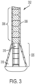
- FIG. 3 is a variable diameter fuel rod 302 comprising an axial reflector region 305 having a first diameter, and a middle axial region 306 having a second diameter, in accordance with at least one aspect of the present disclosure.
- the variable diameter fuel rod 302 comprises a larger diameter fuel rod cladding in the axial reflector region 305.
- the larger diameter cladding 308 increases the internal void volume within the unoccupied space 318 of the axial reflector region 305 of the variable diameter fuel rod 302, in comparison to a constant diameter fuel rods 102, 202 shown in FIGS. 1 and 2 .
- the total internal void volume within the fuel rod is calculated by taking the summation of all unoccupied space within the sealed fuel rod.
- the unoccupied spaces within the fuel rod includes the "dish" dimples on either end of fuel pellets, the chamfered edged of fuel pellets, the space between the fuel pellets and the cladding wall, the internal volume of annular fuel pellets 316, and the unoccupied space 318 of the axial reflector regions 304.
- the variable diameter fuel rod may have a larger diameter cladding in one or both of the axial reflector regions.
- variable diameter fuel rod 402 comprises a cladding 408 and a plurality of fuel pellets 410.
- the variable diameter fuel rod 402 may be implemented into a fuel rod assembly 400 with the existing components such as the fuel rod grid 424, or may require minor modification to compensate for any dimensional changes.
- the variable diameter fuel bundle 420 may be retrofitted to support variable diameter fuel rod 402 by considering the pitch of adjacent fuel rods, the diameter of the fuel rod cladding, the location of control rods, and the space needed for coolant to flow within the variable fuel rod bundle.
- FIG. 4 illustrates a fuel rod assembly 400, including control rods 422 that are periodically inserted into the fuel rod bundle at various stages of the reactor operation.
- the fuel rods 402 in the fuel rod bundle 420 must be arranged in a predetermined configuration that provides a gap for the control rods to be inserted into the fuel rod bundle.
- a fuel rod grid 424 arranges the fuel rods 402 in a fuel rod bundle 420 in according to a specific spacing and distance between the fuel rods, known as the pitch.
- the pitch 512 between two adjacent fuel rods 502, 504 is defined as the center-to-center distance between one fuel rod 502 and an adjacent fuel rod 504.
- the pitch 512 may be defined as the sum of the radius 508 of fuel rod 502, radius 510 of the adjacent fuel rod 504, and gap 514 defined between the outside surface of the radius of each of the fuel rods 502, 504.
- the gap 514 is a value greater than zero such that the fuel rods 502, 504 are not in contact and a space is provided for coolant to flow in the fuel rod bundle 500 in a space 516 defined between the fuel rods 502, 504 and the control rod 506.
- the pitch between fuel rods is directly related to the maximum diameter of the adjacent fuel rods.
- the outside cladding diameter d 3 of the second axial reflector regions 518, 520 of the fuel rods 502, 504, respectively, is larger than the outside cladding diameter d 2 in the middle axial reflector regions 522, 524 and the outside cladding diameter d 1 in the first axial reflector regions 526, 528 of the fuel rods 502, 504.
- the cladding outside diameter d 1 of the first axial reflector regions 526, 528 may be limited by the spatial constrains of the cladding outside diameter d 4 of the control rod 506 or location of the control rod 506.
- Control rods 506 are typically only used at the top of the fuel assembly and may allow the second axial reflector regions 518, 520 to support a slightly larger diameter cladding.
- the second axial reflector regions 518, 520 may have the largest cladding outside diameter, where d 3 > d 2 ⁇ d 1 .
- the diameter d 2 of the middle axial regions 522, 524 transitions to the larger diameter d 3 at transitional regions 532, 534, respectively.
- FIG. 6 is a side view of a representative bundle 600 of two adjacent variable diameter fuel rods 602, 604 having a larger diameter on both ends 630, 632 to illustrate the spatial relationship between the variable diameter fuel rods 602, 604 and a control rod 606, and the pitch between adjacent fuel rods, in accordance with at least one aspect of the present disclosure.
- FIG. 6 illustrates an aspect where there is a sufficient pitch distance 612 between adjacent fuel rods 602, 604 to support a larger diameter cladding for both the first axial reflector regions 626, 628 and the second axial reflector regions 618, 620. Additionally, there is sufficient space in gap 616 for coolant to flow through the fuel rod bundle 600.
- both the first axial reflector regions 626, 628 and the second axial reflector regions 618, 620 may have the substantially larger cladding diameters than the middle axial region.
- the outside cladding diameter d 4 of the first axial reflector regions 626, 628 of the fuel rods 602, 604, respectively, is larger than the outside cladding diameter d 5 in the middle axial reflector regions 622, 624.
- the outside cladding diameter d 6 of the second axial reflector regions 618, 620 of the fuel rods 602, 604, respectively, is larger than the outside cladding diameter d 5 in the middle axial reflector regions 622, 624, where d 4 > d 5 and d 6 > d 5 .
- the diameter d 5 of the middle axial regions 622, 624 transitions to the larger diameter d 4 of the first axial reflector regions 626, 628 at transitional regions 642, 644, respectively. Further, the diameter d 5 of the middle axial regions 622, 624 transitions to the larger diameter d 6 of the second axial reflector regions 618, 620 at transitional regions 632, 634, respectively.
- Variable diameter fuel rod 502 may provide cost saving advantages over fuel rod 602. Increasing the cladding diameter in only one axial reflector region may minimize the number of associated components that require modifications. Although variable diameter fuel rod 602 has a greater internal void volume than fuel rod 502, the implementation may be based on a number of design factors.
- the shape of the transitional region may also be dictated by a number of factors.
- the shape of the transitional slope between a between two different diameter sections may be determined according to manufacturing costs, structural integrity related to the manufacturing process, and sufficient space to accommodate coolant and control rods.
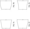
- FIG. 7A-7D illustrate a profile view of the fuel rod cladding and highlight a transitional slope between a larger axial reflector region.
- FIG. 7A and 7C illustrate transitional slopes that are defined by a linear function, whereas the transitional slope in FIG. 7B and 7D are defined by exponential functions. The specific slope may also be determined based on a maximization of the void volume.
- FIG. 8A illustrates a cross-sectional view of the middle axial region 702 of a variable diameter fuel rod.
- the unoccupied space 710 between the fuel pellet 706 and the fuel rod cladding 708 is determined by the difference between radius 710 and the radius 712.
- FIG. 8B illustrates a cross-sectional view of an axial reflector region 704 of a variable diameter fuel rod.
- the unoccupied space 716 between the fuel pellet 706 and the fuel rod cladding 708 is determined by the difference between radius 710 and the radius 712.
- the difference between the unoccupied space 510 and 512 represents an increase in the void volume of the fuel rod.
- the width of the fuel rod cladding in the middle axial region 702 is the same as the width in the axial reflector region 704.
- FIG. 9 and 10 illustrate aspects that to maximize the internal void volume.
- FIG. 9 is a variable diameter fuel rod 802 comprising a first cladding diameter in the first axial reflector region 804, a second cladding diameter in the middle axial region 806, and a third cladding diameter in the second axial reflector regions 805.
- FIG. 9 illustrates an aspect that employs annular fuel pellets 812 in the axial reflector regions 804, 805 as well as a larger diameter cladding in both the first and second axial reflector regions 804, 805 resulting in an increased void volume 818, 820.
- FIG. 10 is a variable diameter fuel rod comprising a first cladding diameter in the first axial reflector region 904 and the middle axial region 905, and a second cladding diameter in the second axial reflector region 905. While FIG. 8 also employs annular fuel pellets 912 in the axial reflector regions 904, 905, only the second axial reflector region 905 comprises a larger diameter cladding. Thus, the increase in cladding diameter only increases the void volume 918 in the second axial reflector region.
- any reference to “one aspect,” “an aspect,” “an exemplification,” “one exemplification,” and the like means that a particular feature, structure, or characteristic described in connection with the aspect is included in at least one aspect.
- appearances of the phrases “in one aspect,” “in an aspect,” “in an exemplification,” and “in one exemplification” in various places throughout the present disclosure are not necessarily all referring to the same aspect.
- the particular features, structures or characteristics may be combined in any suitable manner in one or more aspects.
- the terms “about” or “approximately” as used in the present disclosure means an acceptable error for a particular value as determined by one of ordinary skill in the art, which depends in part on how the value is measured or determined. In certain aspects, the term “about” or “approximately” means within 1, 2, 3, or 4 standard deviations. In certain aspects, the term “about” or “approximately” means within 50%, 200%, 105%, 100%, 9%, 8%, 7%, 6%, 5%, 4%, 3%, 2%, 1%, 0.5%, or 0.05% of a given value or range.
- any numerical range recited herein includes all sub-ranges subsumed within the recited range.
- a range of "1 to 100" includes all sub-ranges between (and including) the recited minimum value of 1 and the recited maximum value of 100, that is, having a minimum value equal to or greater than 1 and a maximum value equal to or less than 100.
- all ranges recited herein are inclusive of the end points of the recited ranges.
- a range of "1 to 100” includes the end points 1 and 100.
- Any maximum numerical limitation recited in the present disclosure is intended to include all lower numerical limitations subsumed therein, and any minimum numerical limitation recited in the present disclosure is intended to include all higher numerical limitations subsumed therein. Accordingly, Applicant reserves the right to amend the present disclosure, including the claims, to expressly recite any sub-range subsumed within the ranges expressly recited. All such ranges are inherently described in the present disclosure.
Landscapes
- Physics & Mathematics (AREA)
- Engineering & Computer Science (AREA)
- Plasma & Fusion (AREA)
- General Engineering & Computer Science (AREA)
- High Energy & Nuclear Physics (AREA)
- Chemical & Material Sciences (AREA)
- Chemical Kinetics & Catalysis (AREA)
- Monitoring And Testing Of Nuclear Reactors (AREA)
Applications Claiming Priority (3)
| Application Number | Priority Date | Filing Date | Title |
|---|---|---|---|
| US17/324,904 US12437884B2 (en) | 2021-05-19 | 2021-05-19 | Nuclear fuel rod having cladding with varying diameter |
| PCT/US2022/072364 WO2022246397A2 (en) | 2021-05-19 | 2022-05-17 | Variable fuel rod diameter |
| EP22735741.5A EP4341965A2 (de) | 2021-05-19 | 2022-05-17 | Variabler brennstabdurchmesser |
Related Parent Applications (2)
| Application Number | Title | Priority Date | Filing Date |
|---|---|---|---|
| EP22735741.5A Division-Into EP4341965A2 (de) | 2021-05-19 | 2022-05-17 | Variabler brennstabdurchmesser |
| EP22735741.5A Division EP4341965A2 (de) | 2021-05-19 | 2022-05-17 | Variabler brennstabdurchmesser |
Publications (2)
| Publication Number | Publication Date |
|---|---|
| EP4365915A2 true EP4365915A2 (de) | 2024-05-08 |
| EP4365915A3 EP4365915A3 (de) | 2024-07-31 |
Family
ID=82321320
Family Applications (2)
| Application Number | Title | Priority Date | Filing Date |
|---|---|---|---|
| EP22735741.5A Pending EP4341965A2 (de) | 2021-05-19 | 2022-05-17 | Variabler brennstabdurchmesser |
| EP24158749.2A Pending EP4365915A3 (de) | 2021-05-19 | 2022-05-17 | Variabler brennstabdurchmesser |
Family Applications Before (1)
| Application Number | Title | Priority Date | Filing Date |
|---|---|---|---|
| EP22735741.5A Pending EP4341965A2 (de) | 2021-05-19 | 2022-05-17 | Variabler brennstabdurchmesser |
Country Status (6)
| Country | Link |
|---|---|
| US (2) | US12437884B2 (de) |
| EP (2) | EP4341965A2 (de) |
| JP (1) | JP2024519870A (de) |
| KR (1) | KR20240008912A (de) |
| TW (1) | TW202309930A (de) |
| WO (1) | WO2022246397A2 (de) |
Families Citing this family (2)
| Publication number | Priority date | Publication date | Assignee | Title |
|---|---|---|---|---|
| US11710577B2 (en) * | 2019-10-15 | 2023-07-25 | Nuscale Power, Llc | Nuclear reactors having liquid metal alloy fuels and/or moderators |
| CN117747138A (zh) * | 2023-11-28 | 2024-03-22 | 中广核研究院有限公司 | 快堆燃料棒 |
Family Cites Families (34)
| Publication number | Priority date | Publication date | Assignee | Title |
|---|---|---|---|---|
| US3031388A (en) * | 1957-09-17 | 1962-04-24 | Martin Marietta Corp | Fuel element for nuclear reactors |
| NL123308C (de) * | 1958-03-17 | |||
| US3255092A (en) * | 1961-03-24 | 1966-06-07 | Gen Dynamics Corp | Control rods |
| US3211627A (en) * | 1962-02-05 | 1965-10-12 | Westinghouse Electric Corp | Fuel element for a coolant-moderator nuclear reactor |
| DE1464956C3 (de) * | 1964-08-01 | 1974-06-27 | Gesellschaft Fuer Kernforschung Mbh, 7500 Karlsruhe | Stabbündelbrennelement für einen Kernreaktor |
| US3215606A (en) | 1965-03-29 | 1965-11-02 | Austin G Silvester | Nuclear reactor with emergency coolant cross flow |
| US3291698A (en) * | 1965-04-19 | 1966-12-13 | Fortescne Peter | Fuel element |
| US3466226A (en) * | 1966-01-26 | 1969-09-09 | Gen Electric | Nuclear fuel element |
| US3546068A (en) | 1967-11-01 | 1970-12-08 | Babcock & Wilcox Co | Nuclear reactor core construction |
| US3454468A (en) * | 1968-03-29 | 1969-07-08 | Atomic Energy Commission | Fuel element for neutronic reactor and method of fabrication thereof |
| US3679545A (en) * | 1969-06-02 | 1972-07-25 | Babcock & Wilcox Co | Nuclear fuel rod |
| FR2416529A1 (fr) | 1978-02-06 | 1979-08-31 | Westinghouse Electric Corp | Assemblage combustible nucleaire composite |
| JPS58142292A (ja) * | 1982-02-19 | 1983-08-24 | 株式会社日立製作所 | 燃料棒 |
| JPS6117977A (ja) * | 1984-07-04 | 1986-01-25 | 日本原子力事業株式会社 | 燃料ピン |
| US4994233A (en) * | 1989-01-27 | 1991-02-19 | Westinghouse Electric Corp. | Fuel rod with axial regions of annular and standard fuel pellets |
| EP0395920A3 (de) * | 1989-05-01 | 1991-05-02 | Westinghouse Electric Corporation | Kernbrennstoff mit abbrennbarem Neutronengiftüberzug |
| JP3037717B2 (ja) * | 1990-04-27 | 2000-05-08 | 株式会社東芝 | 原子炉の燃料集合体 |
| US5416812A (en) * | 1991-05-17 | 1995-05-16 | General Electric Company | Optimized critical power in a fuel bundle with part length rods |
| EP0514121B1 (de) | 1991-05-17 | 1996-08-21 | General Electric Company | Kernbrennstabbündel mit Brennstäben von zwei Durchmessern |
| JP3141452B2 (ja) * | 1991-10-24 | 2001-03-05 | 株式会社日立製作所 | 燃料集合体 |
| US5219519A (en) * | 1992-02-21 | 1993-06-15 | General Electric Company | Increased fuel column height for boiling water reactor fuel rods |
| JPH06342090A (ja) * | 1993-05-28 | 1994-12-13 | Nuclear Fuel Ind Ltd | 燃料棒 |
| SE504360C2 (sv) * | 1995-05-24 | 1997-01-20 | Asea Atom Ab | Bränslepatron för kokarvattenreaktor innefattande en grupp bränslestavar med ett fissionsgasplenum omslutet av ett plenumrör |
| JP3683975B2 (ja) | 1996-03-14 | 2005-08-17 | 株式会社東芝 | 核燃料棒 |
| SE506818C2 (sv) * | 1996-06-20 | 1998-02-16 | Asea Atom Ab | Kärnbränslepatron |
| GB9620569D0 (en) * | 1996-10-02 | 1996-11-20 | British Nuclear Fuels Plc | Improvements in and relating to fuels |
| SE522371C2 (sv) * | 1998-12-23 | 2004-02-03 | Westinghouse Atom Ab | Bränslepatron för en lättvattenreaktor |
| GB0000241D0 (en) | 2000-01-07 | 2000-03-01 | British Nuclear Fuels Plc | Improvements in and relating to nuclear fuel assemblies |
| US20060269036A1 (en) * | 2003-06-30 | 2006-11-30 | Yasushi Hanayama | Mox fuel assembly for pressurized water reactors |
| US20100054389A1 (en) * | 2008-08-26 | 2010-03-04 | Fetterman Robert J | Mixed oxide fuel assembly |
| WO2012174548A1 (en) | 2011-06-16 | 2012-12-20 | Ceramic Tubular Products Llc | Nuclear reactor fuel element having silicon carbide multilayered cladding and thoria-based fissionable fuel |
| US20140169516A1 (en) * | 2012-12-14 | 2014-06-19 | Global Nuclear Fuel - Americas, Llc | Fuel rods with varying axial characteristics and nuclear fuel assemblies including the same |
| ES2775010T3 (es) | 2017-04-26 | 2020-07-23 | Westinghouse Electric Sweden Ab | Una pastilla de combustible nuclear cerámica, una barra de combustible y un conjunto combustible |
| WO2019125604A2 (en) * | 2017-10-31 | 2019-06-27 | Westinghouse Electric Company Llc | High temperature nuclear fuel system for thermal neutron reactors |
-
2021
- 2021-05-19 US US17/324,904 patent/US12437884B2/en active Active
-
2022
- 2022-05-17 EP EP22735741.5A patent/EP4341965A2/de active Pending
- 2022-05-17 EP EP24158749.2A patent/EP4365915A3/de active Pending
- 2022-05-17 KR KR1020237043226A patent/KR20240008912A/ko active Pending
- 2022-05-17 WO PCT/US2022/072364 patent/WO2022246397A2/en not_active Ceased
- 2022-05-17 JP JP2023571630A patent/JP2024519870A/ja active Pending
- 2022-05-19 TW TW111118737A patent/TW202309930A/zh unknown
-
2025
- 2025-07-09 US US19/264,413 patent/US20250342977A1/en active Pending
Also Published As
| Publication number | Publication date |
|---|---|
| US12437884B2 (en) | 2025-10-07 |
| US20250342977A1 (en) | 2025-11-06 |
| JP2024519870A (ja) | 2024-05-21 |
| EP4341965A2 (de) | 2024-03-27 |
| WO2022246397A3 (en) | 2022-12-29 |
| KR20240008912A (ko) | 2024-01-19 |
| EP4365915A3 (de) | 2024-07-31 |
| TW202309930A (zh) | 2023-03-01 |
| US20220375632A1 (en) | 2022-11-24 |
| WO2022246397A2 (en) | 2022-11-24 |
Similar Documents
| Publication | Publication Date | Title |
|---|---|---|
| US20250342977A1 (en) | Nuclear fuel rod having cladding with varying diameter | |
| US5349618A (en) | BWR fuel assembly having oxide and hydride fuel | |
| EP1085525B1 (de) | Leichtwasserreaktorkern und Brennstabbündel | |
| WO2010074592A1 (ru) | Топливная сборка легководного ядерного реактора (варианты), легководный ядерный реактор и топливный элемент топливной сборки | |
| EP1647993A2 (de) | Verwendung von Bor oder angereichertem Bor in UO2 | |
| CN101911211A (zh) | 核反应堆(可选的)、用于核反应堆(可选的)的点火区-再生区子组件的燃料组件和用于燃料组件的燃料元件 | |
| CN110827998B (zh) | 一种氧化铍慢化金属冷却反应堆小型化设计方法及反应堆 | |
| EP2887357A1 (de) | Kernreaktor-Flussreduktionssysteme und Verfahren | |
| US5555281A (en) | Triangular lattice for LWR square fuel assemblies | |
| RU2639712C2 (ru) | Тепловыделяющая сборка для ядерного реактора | |
| US6002735A (en) | Nuclear fuel pellet | |
| US5991354A (en) | Nuclear fuel pellet | |
| JPH09211163A5 (de) | ||
| US4507259A (en) | Axially staggered seed-blanket reactor fuel module construction | |
| US9437335B2 (en) | Designed porosity materials in nuclear reactor components | |
| RU2428756C1 (ru) | Бесчехловая тепловыделяющая сборка с гексагональной топливной решеткой водо-водяного энергетического реактора (варианты) | |
| JPH0339277B2 (de) | ||
| US4701296A (en) | Fuel array for an undermoderated nuclear reactor | |
| RU6465U1 (ru) | Тепловыделяющая сборка | |
| EP1780729A2 (de) | Brennstabbündel mit borhaltigem Kernbrennstoff | |
| KR101744156B1 (ko) | 개량형 중수로용 핵연료 다발 | |
| RU2428755C1 (ru) | Бесчехловая тепловыделяющая сборка с гексагональной топливной решеткой водо-водяного энергетического реактора (варианты) | |
| Sterbentz | Low-enriched fuel design concept for the prismatic very high temperature reactor core | |
| Saji et al. | Control rod worth in high conversion PWR | |
| JP2024007691A (ja) | 高速炉の炉心 |
Legal Events
| Date | Code | Title | Description |
|---|---|---|---|
| PUAI | Public reference made under article 153(3) epc to a published international application that has entered the european phase |
Free format text: ORIGINAL CODE: 0009012 |
|
| STAA | Information on the status of an ep patent application or granted ep patent |
Free format text: STATUS: THE APPLICATION HAS BEEN PUBLISHED |
|
| AC | Divisional application: reference to earlier application |
Ref document number: 4341965 Country of ref document: EP Kind code of ref document: P |
|
| AK | Designated contracting states |
Kind code of ref document: A2 Designated state(s): AL AT BE BG CH CY CZ DE DK EE ES FI FR GB GR HR HU IE IS IT LI LT LU LV MC MK MT NL NO PL PT RO RS SE SI SK SM TR |
|
| REG | Reference to a national code |
Ref country code: DE Ref legal event code: R079 Free format text: PREVIOUS MAIN CLASS: G21C0003320000 Ipc: G21C0003040000 |
|
| PUAL | Search report despatched |
Free format text: ORIGINAL CODE: 0009013 |
|
| AK | Designated contracting states |
Kind code of ref document: A3 Designated state(s): AL AT BE BG CH CY CZ DE DK EE ES FI FR GB GR HR HU IE IS IT LI LT LU LV MC MK MT NL NO PL PT RO RS SE SI SK SM TR |
|
| RIC1 | Information provided on ipc code assigned before grant |
Ipc: G21C 3/32 20060101ALI20240624BHEP Ipc: G21C 3/17 20060101ALI20240624BHEP Ipc: G21C 3/04 20060101AFI20240624BHEP |
|
| STAA | Information on the status of an ep patent application or granted ep patent |
Free format text: STATUS: REQUEST FOR EXAMINATION WAS MADE |
|
| 17P | Request for examination filed |
Effective date: 20250127 |