EP4363759B1 - Kraftstoffsystem für einen drucktank und für ein gasbetriebenes fahrzeug - Google Patents
Kraftstoffsystem für einen drucktank und für ein gasbetriebenes fahrzeug Download PDFInfo
- Publication number
- EP4363759B1 EP4363759B1 EP22738418.7A EP22738418A EP4363759B1 EP 4363759 B1 EP4363759 B1 EP 4363759B1 EP 22738418 A EP22738418 A EP 22738418A EP 4363759 B1 EP4363759 B1 EP 4363759B1
- Authority
- EP
- European Patent Office
- Prior art keywords
- pressure
- fuel system
- tank
- unit
- valve
- Prior art date
- Legal status (The legal status is an assumption and is not a legal conclusion. Google has not performed a legal analysis and makes no representation as to the accuracy of the status listed.)
- Active
Links
Images

Classifications
-
- B—PERFORMING OPERATIONS; TRANSPORTING
- B60—VEHICLES IN GENERAL
- B60K—ARRANGEMENT OR MOUNTING OF PROPULSION UNITS OR OF TRANSMISSIONS IN VEHICLES; ARRANGEMENT OR MOUNTING OF PLURAL DIVERSE PRIME-MOVERS IN VEHICLES; AUXILIARY DRIVES FOR VEHICLES; INSTRUMENTATION OR DASHBOARDS FOR VEHICLES; ARRANGEMENTS IN CONNECTION WITH COOLING, AIR INTAKE, GAS EXHAUST OR FUEL SUPPLY OF PROPULSION UNITS IN VEHICLES
- B60K15/00—Arrangement in connection with fuel supply of combustion engines or other fuel consuming energy converters, e.g. fuel cells; Mounting or construction of fuel tanks
- B60K15/03—Fuel tanks
- B60K15/03006—Gas tanks
-
- F—MECHANICAL ENGINEERING; LIGHTING; HEATING; WEAPONS; BLASTING
- F17—STORING OR DISTRIBUTING GASES OR LIQUIDS
- F17C—VESSELS FOR CONTAINING OR STORING COMPRESSED, LIQUEFIED OR SOLIDIFIED GASES; FIXED-CAPACITY GAS-HOLDERS; FILLING VESSELS WITH, OR DISCHARGING FROM VESSELS, COMPRESSED, LIQUEFIED, OR SOLIDIFIED GASES
- F17C7/00—Methods or apparatus for discharging liquefied, solidified, or compressed gases from pressure vessels, not covered by another subclass
-
- B—PERFORMING OPERATIONS; TRANSPORTING
- B60—VEHICLES IN GENERAL
- B60K—ARRANGEMENT OR MOUNTING OF PROPULSION UNITS OR OF TRANSMISSIONS IN VEHICLES; ARRANGEMENT OR MOUNTING OF PLURAL DIVERSE PRIME-MOVERS IN VEHICLES; AUXILIARY DRIVES FOR VEHICLES; INSTRUMENTATION OR DASHBOARDS FOR VEHICLES; ARRANGEMENTS IN CONNECTION WITH COOLING, AIR INTAKE, GAS EXHAUST OR FUEL SUPPLY OF PROPULSION UNITS IN VEHICLES
- B60K15/00—Arrangement in connection with fuel supply of combustion engines or other fuel consuming energy converters, e.g. fuel cells; Mounting or construction of fuel tanks
-
- F—MECHANICAL ENGINEERING; LIGHTING; HEATING; WEAPONS; BLASTING
- F02—COMBUSTION ENGINES; HOT-GAS OR COMBUSTION-PRODUCT ENGINE PLANTS
- F02M—SUPPLYING COMBUSTION ENGINES IN GENERAL WITH COMBUSTIBLE MIXTURES OR CONSTITUENTS THEREOF
- F02M21/00—Apparatus for supplying engines with non-liquid fuels, e.g. gaseous fuels stored in liquid form
- F02M21/02—Apparatus for supplying engines with non-liquid fuels, e.g. gaseous fuels stored in liquid form for gaseous fuels
- F02M21/0203—Apparatus for supplying engines with non-liquid fuels, e.g. gaseous fuels stored in liquid form for gaseous fuels characterised by the type of gaseous fuel
- F02M21/0206—Non-hydrocarbon fuels, e.g. hydrogen, ammonia or carbon monoxide
-
- F—MECHANICAL ENGINEERING; LIGHTING; HEATING; WEAPONS; BLASTING
- F02—COMBUSTION ENGINES; HOT-GAS OR COMBUSTION-PRODUCT ENGINE PLANTS
- F02M—SUPPLYING COMBUSTION ENGINES IN GENERAL WITH COMBUSTIBLE MIXTURES OR CONSTITUENTS THEREOF
- F02M21/00—Apparatus for supplying engines with non-liquid fuels, e.g. gaseous fuels stored in liquid form
- F02M21/02—Apparatus for supplying engines with non-liquid fuels, e.g. gaseous fuels stored in liquid form for gaseous fuels
- F02M21/0218—Details on the gaseous fuel supply system, e.g. tanks, valves, pipes, pumps, rails, injectors or mixers
- F02M21/023—Valves; Pressure or flow regulators in the fuel supply or return system
- F02M21/0239—Pressure or flow regulators therefor
-
- F—MECHANICAL ENGINEERING; LIGHTING; HEATING; WEAPONS; BLASTING
- F02—COMBUSTION ENGINES; HOT-GAS OR COMBUSTION-PRODUCT ENGINE PLANTS
- F02M—SUPPLYING COMBUSTION ENGINES IN GENERAL WITH COMBUSTIBLE MIXTURES OR CONSTITUENTS THEREOF
- F02M21/00—Apparatus for supplying engines with non-liquid fuels, e.g. gaseous fuels stored in liquid form
- F02M21/02—Apparatus for supplying engines with non-liquid fuels, e.g. gaseous fuels stored in liquid form for gaseous fuels
- F02M21/0218—Details on the gaseous fuel supply system, e.g. tanks, valves, pipes, pumps, rails, injectors or mixers
- F02M21/023—Valves; Pressure or flow regulators in the fuel supply or return system
- F02M21/0242—Shut-off valves; Check valves; Safety valves; Pressure relief valves
-
- B—PERFORMING OPERATIONS; TRANSPORTING
- B60—VEHICLES IN GENERAL
- B60K—ARRANGEMENT OR MOUNTING OF PROPULSION UNITS OR OF TRANSMISSIONS IN VEHICLES; ARRANGEMENT OR MOUNTING OF PLURAL DIVERSE PRIME-MOVERS IN VEHICLES; AUXILIARY DRIVES FOR VEHICLES; INSTRUMENTATION OR DASHBOARDS FOR VEHICLES; ARRANGEMENTS IN CONNECTION WITH COOLING, AIR INTAKE, GAS EXHAUST OR FUEL SUPPLY OF PROPULSION UNITS IN VEHICLES
- B60K15/00—Arrangement in connection with fuel supply of combustion engines or other fuel consuming energy converters, e.g. fuel cells; Mounting or construction of fuel tanks
- B60K15/03—Fuel tanks
- B60K15/03006—Gas tanks
- B60K2015/03026—Gas tanks comprising a valve
-
- B—PERFORMING OPERATIONS; TRANSPORTING
- B60—VEHICLES IN GENERAL
- B60K—ARRANGEMENT OR MOUNTING OF PROPULSION UNITS OR OF TRANSMISSIONS IN VEHICLES; ARRANGEMENT OR MOUNTING OF PLURAL DIVERSE PRIME-MOVERS IN VEHICLES; AUXILIARY DRIVES FOR VEHICLES; INSTRUMENTATION OR DASHBOARDS FOR VEHICLES; ARRANGEMENTS IN CONNECTION WITH COOLING, AIR INTAKE, GAS EXHAUST OR FUEL SUPPLY OF PROPULSION UNITS IN VEHICLES
- B60K15/00—Arrangement in connection with fuel supply of combustion engines or other fuel consuming energy converters, e.g. fuel cells; Mounting or construction of fuel tanks
- B60K15/03—Fuel tanks
- B60K2015/0321—Fuel tanks characterised by special sensors, the mounting thereof
- B60K2015/0323—Sensors for detecting presence or absence of the filling nozzle
-
- B—PERFORMING OPERATIONS; TRANSPORTING
- B60—VEHICLES IN GENERAL
- B60K—ARRANGEMENT OR MOUNTING OF PROPULSION UNITS OR OF TRANSMISSIONS IN VEHICLES; ARRANGEMENT OR MOUNTING OF PLURAL DIVERSE PRIME-MOVERS IN VEHICLES; AUXILIARY DRIVES FOR VEHICLES; INSTRUMENTATION OR DASHBOARDS FOR VEHICLES; ARRANGEMENTS IN CONNECTION WITH COOLING, AIR INTAKE, GAS EXHAUST OR FUEL SUPPLY OF PROPULSION UNITS IN VEHICLES
- B60K15/00—Arrangement in connection with fuel supply of combustion engines or other fuel consuming energy converters, e.g. fuel cells; Mounting or construction of fuel tanks
- B60K15/03—Fuel tanks
- B60K2015/03309—Tanks specially adapted for particular fuels
- B60K2015/03315—Tanks specially adapted for particular fuels for hydrogen
-
- F—MECHANICAL ENGINEERING; LIGHTING; HEATING; WEAPONS; BLASTING
- F17—STORING OR DISTRIBUTING GASES OR LIQUIDS
- F17C—VESSELS FOR CONTAINING OR STORING COMPRESSED, LIQUEFIED OR SOLIDIFIED GASES; FIXED-CAPACITY GAS-HOLDERS; FILLING VESSELS WITH, OR DISCHARGING FROM VESSELS, COMPRESSED, LIQUEFIED, OR SOLIDIFIED GASES
- F17C2201/00—Vessel construction, in particular geometry, arrangement or size
- F17C2201/01—Shape
- F17C2201/0104—Shape cylindrical
- F17C2201/0109—Shape cylindrical with exteriorly curved end-piece
-
- F—MECHANICAL ENGINEERING; LIGHTING; HEATING; WEAPONS; BLASTING
- F17—STORING OR DISTRIBUTING GASES OR LIQUIDS
- F17C—VESSELS FOR CONTAINING OR STORING COMPRESSED, LIQUEFIED OR SOLIDIFIED GASES; FIXED-CAPACITY GAS-HOLDERS; FILLING VESSELS WITH, OR DISCHARGING FROM VESSELS, COMPRESSED, LIQUEFIED, OR SOLIDIFIED GASES
- F17C2201/00—Vessel construction, in particular geometry, arrangement or size
- F17C2201/05—Size
- F17C2201/056—Small (<1 m3)
-
- F—MECHANICAL ENGINEERING; LIGHTING; HEATING; WEAPONS; BLASTING
- F17—STORING OR DISTRIBUTING GASES OR LIQUIDS
- F17C—VESSELS FOR CONTAINING OR STORING COMPRESSED, LIQUEFIED OR SOLIDIFIED GASES; FIXED-CAPACITY GAS-HOLDERS; FILLING VESSELS WITH, OR DISCHARGING FROM VESSELS, COMPRESSED, LIQUEFIED, OR SOLIDIFIED GASES
- F17C2205/00—Vessel construction, in particular mounting arrangements, attachments or identifications means
- F17C2205/01—Mounting arrangements
- F17C2205/0123—Mounting arrangements characterised by number of vessels
- F17C2205/013—Two or more vessels
- F17C2205/0134—Two or more vessels characterised by the presence of fluid connection between vessels
- F17C2205/0142—Two or more vessels characterised by the presence of fluid connection between vessels bundled in parallel
-
- F—MECHANICAL ENGINEERING; LIGHTING; HEATING; WEAPONS; BLASTING
- F17—STORING OR DISTRIBUTING GASES OR LIQUIDS
- F17C—VESSELS FOR CONTAINING OR STORING COMPRESSED, LIQUEFIED OR SOLIDIFIED GASES; FIXED-CAPACITY GAS-HOLDERS; FILLING VESSELS WITH, OR DISCHARGING FROM VESSELS, COMPRESSED, LIQUEFIED, OR SOLIDIFIED GASES
- F17C2205/00—Vessel construction, in particular mounting arrangements, attachments or identifications means
- F17C2205/01—Mounting arrangements
- F17C2205/0123—Mounting arrangements characterised by number of vessels
- F17C2205/013—Two or more vessels
- F17C2205/0134—Two or more vessels characterised by the presence of fluid connection between vessels
- F17C2205/0146—Two or more vessels characterised by the presence of fluid connection between vessels with details of the manifold
-
- F—MECHANICAL ENGINEERING; LIGHTING; HEATING; WEAPONS; BLASTING
- F17—STORING OR DISTRIBUTING GASES OR LIQUIDS
- F17C—VESSELS FOR CONTAINING OR STORING COMPRESSED, LIQUEFIED OR SOLIDIFIED GASES; FIXED-CAPACITY GAS-HOLDERS; FILLING VESSELS WITH, OR DISCHARGING FROM VESSELS, COMPRESSED, LIQUEFIED, OR SOLIDIFIED GASES
- F17C2205/00—Vessel construction, in particular mounting arrangements, attachments or identifications means
- F17C2205/03—Fluid connections, filters, valves, closure means or other attachments
- F17C2205/0302—Fittings, valves, filters, or components in connection with the gas storage device
- F17C2205/0323—Valves
- F17C2205/0326—Valves electrically actuated
-
- F—MECHANICAL ENGINEERING; LIGHTING; HEATING; WEAPONS; BLASTING
- F17—STORING OR DISTRIBUTING GASES OR LIQUIDS
- F17C—VESSELS FOR CONTAINING OR STORING COMPRESSED, LIQUEFIED OR SOLIDIFIED GASES; FIXED-CAPACITY GAS-HOLDERS; FILLING VESSELS WITH, OR DISCHARGING FROM VESSELS, COMPRESSED, LIQUEFIED, OR SOLIDIFIED GASES
- F17C2205/00—Vessel construction, in particular mounting arrangements, attachments or identifications means
- F17C2205/03—Fluid connections, filters, valves, closure means or other attachments
- F17C2205/0302—Fittings, valves, filters, or components in connection with the gas storage device
- F17C2205/0323—Valves
- F17C2205/0332—Safety valves or pressure relief valves
-
- F—MECHANICAL ENGINEERING; LIGHTING; HEATING; WEAPONS; BLASTING
- F17—STORING OR DISTRIBUTING GASES OR LIQUIDS
- F17C—VESSELS FOR CONTAINING OR STORING COMPRESSED, LIQUEFIED OR SOLIDIFIED GASES; FIXED-CAPACITY GAS-HOLDERS; FILLING VESSELS WITH, OR DISCHARGING FROM VESSELS, COMPRESSED, LIQUEFIED, OR SOLIDIFIED GASES
- F17C2205/00—Vessel construction, in particular mounting arrangements, attachments or identifications means
- F17C2205/03—Fluid connections, filters, valves, closure means or other attachments
- F17C2205/0302—Fittings, valves, filters, or components in connection with the gas storage device
- F17C2205/0323—Valves
- F17C2205/0335—Check-valves or non-return valves
-
- F—MECHANICAL ENGINEERING; LIGHTING; HEATING; WEAPONS; BLASTING
- F17—STORING OR DISTRIBUTING GASES OR LIQUIDS
- F17C—VESSELS FOR CONTAINING OR STORING COMPRESSED, LIQUEFIED OR SOLIDIFIED GASES; FIXED-CAPACITY GAS-HOLDERS; FILLING VESSELS WITH, OR DISCHARGING FROM VESSELS, COMPRESSED, LIQUEFIED, OR SOLIDIFIED GASES
- F17C2205/00—Vessel construction, in particular mounting arrangements, attachments or identifications means
- F17C2205/03—Fluid connections, filters, valves, closure means or other attachments
- F17C2205/0302—Fittings, valves, filters, or components in connection with the gas storage device
- F17C2205/0338—Pressure regulators
-
- F—MECHANICAL ENGINEERING; LIGHTING; HEATING; WEAPONS; BLASTING
- F17—STORING OR DISTRIBUTING GASES OR LIQUIDS
- F17C—VESSELS FOR CONTAINING OR STORING COMPRESSED, LIQUEFIED OR SOLIDIFIED GASES; FIXED-CAPACITY GAS-HOLDERS; FILLING VESSELS WITH, OR DISCHARGING FROM VESSELS, COMPRESSED, LIQUEFIED, OR SOLIDIFIED GASES
- F17C2205/00—Vessel construction, in particular mounting arrangements, attachments or identifications means
- F17C2205/03—Fluid connections, filters, valves, closure means or other attachments
- F17C2205/0302—Fittings, valves, filters, or components in connection with the gas storage device
- F17C2205/0341—Filters
-
- F—MECHANICAL ENGINEERING; LIGHTING; HEATING; WEAPONS; BLASTING
- F17—STORING OR DISTRIBUTING GASES OR LIQUIDS
- F17C—VESSELS FOR CONTAINING OR STORING COMPRESSED, LIQUEFIED OR SOLIDIFIED GASES; FIXED-CAPACITY GAS-HOLDERS; FILLING VESSELS WITH, OR DISCHARGING FROM VESSELS, COMPRESSED, LIQUEFIED, OR SOLIDIFIED GASES
- F17C2205/00—Vessel construction, in particular mounting arrangements, attachments or identifications means
- F17C2205/03—Fluid connections, filters, valves, closure means or other attachments
- F17C2205/0302—Fittings, valves, filters, or components in connection with the gas storage device
- F17C2205/0382—Constructional details of valves, regulators
- F17C2205/0385—Constructional details of valves, regulators in blocks or units
-
- F—MECHANICAL ENGINEERING; LIGHTING; HEATING; WEAPONS; BLASTING
- F17—STORING OR DISTRIBUTING GASES OR LIQUIDS
- F17C—VESSELS FOR CONTAINING OR STORING COMPRESSED, LIQUEFIED OR SOLIDIFIED GASES; FIXED-CAPACITY GAS-HOLDERS; FILLING VESSELS WITH, OR DISCHARGING FROM VESSELS, COMPRESSED, LIQUEFIED, OR SOLIDIFIED GASES
- F17C2221/00—Handled fluid, in particular type of fluid
- F17C2221/01—Pure fluids
- F17C2221/012—Hydrogen
-
- F—MECHANICAL ENGINEERING; LIGHTING; HEATING; WEAPONS; BLASTING
- F17—STORING OR DISTRIBUTING GASES OR LIQUIDS
- F17C—VESSELS FOR CONTAINING OR STORING COMPRESSED, LIQUEFIED OR SOLIDIFIED GASES; FIXED-CAPACITY GAS-HOLDERS; FILLING VESSELS WITH, OR DISCHARGING FROM VESSELS, COMPRESSED, LIQUEFIED, OR SOLIDIFIED GASES
- F17C2223/00—Handled fluid before transfer, i.e. state of fluid when stored in the vessel or before transfer from the vessel
- F17C2223/01—Handled fluid before transfer, i.e. state of fluid when stored in the vessel or before transfer from the vessel characterised by the phase
- F17C2223/0107—Single phase
- F17C2223/0123—Single phase gaseous, e.g. CNG, GNC
-
- F—MECHANICAL ENGINEERING; LIGHTING; HEATING; WEAPONS; BLASTING
- F17—STORING OR DISTRIBUTING GASES OR LIQUIDS
- F17C—VESSELS FOR CONTAINING OR STORING COMPRESSED, LIQUEFIED OR SOLIDIFIED GASES; FIXED-CAPACITY GAS-HOLDERS; FILLING VESSELS WITH, OR DISCHARGING FROM VESSELS, COMPRESSED, LIQUEFIED, OR SOLIDIFIED GASES
- F17C2223/00—Handled fluid before transfer, i.e. state of fluid when stored in the vessel or before transfer from the vessel
- F17C2223/03—Handled fluid before transfer, i.e. state of fluid when stored in the vessel or before transfer from the vessel characterised by the pressure level
- F17C2223/036—Very high pressure (>80 bar)
-
- F—MECHANICAL ENGINEERING; LIGHTING; HEATING; WEAPONS; BLASTING
- F17—STORING OR DISTRIBUTING GASES OR LIQUIDS
- F17C—VESSELS FOR CONTAINING OR STORING COMPRESSED, LIQUEFIED OR SOLIDIFIED GASES; FIXED-CAPACITY GAS-HOLDERS; FILLING VESSELS WITH, OR DISCHARGING FROM VESSELS, COMPRESSED, LIQUEFIED, OR SOLIDIFIED GASES
- F17C2225/00—Handled fluid after transfer, i.e. state of fluid after transfer from the vessel
- F17C2225/01—Handled fluid after transfer, i.e. state of fluid after transfer from the vessel characterised by the phase
- F17C2225/0107—Single phase
- F17C2225/0123—Single phase gaseous, e.g. CNG, GNC
-
- F—MECHANICAL ENGINEERING; LIGHTING; HEATING; WEAPONS; BLASTING
- F17—STORING OR DISTRIBUTING GASES OR LIQUIDS
- F17C—VESSELS FOR CONTAINING OR STORING COMPRESSED, LIQUEFIED OR SOLIDIFIED GASES; FIXED-CAPACITY GAS-HOLDERS; FILLING VESSELS WITH, OR DISCHARGING FROM VESSELS, COMPRESSED, LIQUEFIED, OR SOLIDIFIED GASES
- F17C2225/00—Handled fluid after transfer, i.e. state of fluid after transfer from the vessel
- F17C2225/03—Handled fluid after transfer, i.e. state of fluid after transfer from the vessel characterised by the pressure level
- F17C2225/033—Small pressure, e.g. for liquefied gas
-
- F—MECHANICAL ENGINEERING; LIGHTING; HEATING; WEAPONS; BLASTING
- F17—STORING OR DISTRIBUTING GASES OR LIQUIDS
- F17C—VESSELS FOR CONTAINING OR STORING COMPRESSED, LIQUEFIED OR SOLIDIFIED GASES; FIXED-CAPACITY GAS-HOLDERS; FILLING VESSELS WITH, OR DISCHARGING FROM VESSELS, COMPRESSED, LIQUEFIED, OR SOLIDIFIED GASES
- F17C2225/00—Handled fluid after transfer, i.e. state of fluid after transfer from the vessel
- F17C2225/03—Handled fluid after transfer, i.e. state of fluid after transfer from the vessel characterised by the pressure level
- F17C2225/035—High pressure, i.e. between 10 and 80 bars
-
- F—MECHANICAL ENGINEERING; LIGHTING; HEATING; WEAPONS; BLASTING
- F17—STORING OR DISTRIBUTING GASES OR LIQUIDS
- F17C—VESSELS FOR CONTAINING OR STORING COMPRESSED, LIQUEFIED OR SOLIDIFIED GASES; FIXED-CAPACITY GAS-HOLDERS; FILLING VESSELS WITH, OR DISCHARGING FROM VESSELS, COMPRESSED, LIQUEFIED, OR SOLIDIFIED GASES
- F17C2227/00—Transfer of fluids, i.e. method or means for transferring the fluid; Heat exchange with the fluid
- F17C2227/03—Heat exchange with the fluid
- F17C2227/0337—Heat exchange with the fluid by cooling
- F17C2227/0341—Heat exchange with the fluid by cooling using another fluid
-
- F—MECHANICAL ENGINEERING; LIGHTING; HEATING; WEAPONS; BLASTING
- F17—STORING OR DISTRIBUTING GASES OR LIQUIDS
- F17C—VESSELS FOR CONTAINING OR STORING COMPRESSED, LIQUEFIED OR SOLIDIFIED GASES; FIXED-CAPACITY GAS-HOLDERS; FILLING VESSELS WITH, OR DISCHARGING FROM VESSELS, COMPRESSED, LIQUEFIED, OR SOLIDIFIED GASES
- F17C2250/00—Accessories; Control means; Indicating, measuring or monitoring of parameters
- F17C2250/03—Control means
- F17C2250/032—Control means using computers
-
- F—MECHANICAL ENGINEERING; LIGHTING; HEATING; WEAPONS; BLASTING
- F17—STORING OR DISTRIBUTING GASES OR LIQUIDS
- F17C—VESSELS FOR CONTAINING OR STORING COMPRESSED, LIQUEFIED OR SOLIDIFIED GASES; FIXED-CAPACITY GAS-HOLDERS; FILLING VESSELS WITH, OR DISCHARGING FROM VESSELS, COMPRESSED, LIQUEFIED, OR SOLIDIFIED GASES
- F17C2250/00—Accessories; Control means; Indicating, measuring or monitoring of parameters
- F17C2250/03—Control means
- F17C2250/034—Control means using wireless transmissions
-
- F—MECHANICAL ENGINEERING; LIGHTING; HEATING; WEAPONS; BLASTING
- F17—STORING OR DISTRIBUTING GASES OR LIQUIDS
- F17C—VESSELS FOR CONTAINING OR STORING COMPRESSED, LIQUEFIED OR SOLIDIFIED GASES; FIXED-CAPACITY GAS-HOLDERS; FILLING VESSELS WITH, OR DISCHARGING FROM VESSELS, COMPRESSED, LIQUEFIED, OR SOLIDIFIED GASES
- F17C2250/00—Accessories; Control means; Indicating, measuring or monitoring of parameters
- F17C2250/04—Indicating or measuring of parameters as input values
- F17C2250/0404—Parameters indicated or measured
- F17C2250/043—Pressure
-
- F—MECHANICAL ENGINEERING; LIGHTING; HEATING; WEAPONS; BLASTING
- F17—STORING OR DISTRIBUTING GASES OR LIQUIDS
- F17C—VESSELS FOR CONTAINING OR STORING COMPRESSED, LIQUEFIED OR SOLIDIFIED GASES; FIXED-CAPACITY GAS-HOLDERS; FILLING VESSELS WITH, OR DISCHARGING FROM VESSELS, COMPRESSED, LIQUEFIED, OR SOLIDIFIED GASES
- F17C2250/00—Accessories; Control means; Indicating, measuring or monitoring of parameters
- F17C2250/04—Indicating or measuring of parameters as input values
- F17C2250/0404—Parameters indicated or measured
- F17C2250/0439—Temperature
-
- F—MECHANICAL ENGINEERING; LIGHTING; HEATING; WEAPONS; BLASTING
- F17—STORING OR DISTRIBUTING GASES OR LIQUIDS
- F17C—VESSELS FOR CONTAINING OR STORING COMPRESSED, LIQUEFIED OR SOLIDIFIED GASES; FIXED-CAPACITY GAS-HOLDERS; FILLING VESSELS WITH, OR DISCHARGING FROM VESSELS, COMPRESSED, LIQUEFIED, OR SOLIDIFIED GASES
- F17C2260/00—Purposes of gas storage and gas handling
- F17C2260/01—Improving mechanical properties or manufacturing
- F17C2260/013—Reducing manufacturing time or effort
-
- F—MECHANICAL ENGINEERING; LIGHTING; HEATING; WEAPONS; BLASTING
- F17—STORING OR DISTRIBUTING GASES OR LIQUIDS
- F17C—VESSELS FOR CONTAINING OR STORING COMPRESSED, LIQUEFIED OR SOLIDIFIED GASES; FIXED-CAPACITY GAS-HOLDERS; FILLING VESSELS WITH, OR DISCHARGING FROM VESSELS, COMPRESSED, LIQUEFIED, OR SOLIDIFIED GASES
- F17C2265/00—Effects achieved by gas storage or gas handling
- F17C2265/06—Fluid distribution
- F17C2265/066—Fluid distribution for feeding engines for propulsion
-
- F—MECHANICAL ENGINEERING; LIGHTING; HEATING; WEAPONS; BLASTING
- F17—STORING OR DISTRIBUTING GASES OR LIQUIDS
- F17C—VESSELS FOR CONTAINING OR STORING COMPRESSED, LIQUEFIED OR SOLIDIFIED GASES; FIXED-CAPACITY GAS-HOLDERS; FILLING VESSELS WITH, OR DISCHARGING FROM VESSELS, COMPRESSED, LIQUEFIED, OR SOLIDIFIED GASES
- F17C2270/00—Applications
- F17C2270/01—Applications for fluid transport or storage
- F17C2270/0165—Applications for fluid transport or storage on the road
- F17C2270/0168—Applications for fluid transport or storage on the road by vehicles
Definitions
- the invention relates to a fuel system intended for installation in a hydrogen-powered vehicle and designed for one or more hydrogen pressure tanks, at a high pressure level of at least 200 bar, wherein the fuel system comprises a connection for an inlet line, a connection for an outlet line and a pressure reducer. And wherein the pressure reducer is designed such that it can reduce the pressure of the hydrogen from the high pressure level from the pressure tank to a medium pressure level between 3 bar and 30 bar.
- Hydrogen-powered vehicles for example, have a gas engine or a fuel cell with an electric motor as a drive. In order to be able to store sufficient fuel, the hydrogen is stored in the tank under high pressure. Pressures of over 200 bar, often 350 bar or 700 bar and sometimes even up to 875 bar are typical for such pressure tanks. Since the gas engine or fuel cell is operated at a lower inlet pressure, the pressure must be reliably regulated from the high pressure level to a low pressure level.
- Fuel systems for hydrogen pressure tanks and for installation in hydrogen-powered vehicles are known in the state of the art. Such systems are used, for example, in the DE 102019200459 A1 , in the WO 2020/079329 A1 , in the FR 2 985 783 A1 and in the DE 102017214184 A1 described.
- a pressure reducer reduces the pressure level from the tank pressure to the lower pressure level required for a fuel cell.
- a control device and a pressure sensor on the pressure tank can be used to determine the fill level and communicate with a filling station if necessary.
- the fuel system also has shut-off valves and pipes that are connected using appropriate screw connections. If several pressure tanks are connected in parallel, there are also distribution points for the various tank lines. All of these components and connection points must be tested and checked after installation. This causes considerable effort and carries risks in terms of incorrect assembly and corresponding leaks.
- the object of the invention is now to further develop and improve a fuel system for a hydrogen-powered vehicle so that it can be operated reliably and safely and can be assembled quickly and error-free.
- the fuel system according to claim 1 is characterized in that it comprises at least the following internal components: A pressure reducer, a gas filter, a shut-off valve, a vent valve, an overpressure safety valve and a pressure sensor, wherein the pressure reducer is designed as a two-stage pressure reducer such that in the first stage it reduces the pressure from the pressure tank to an intermediate level between 40 and 80 bar and in the second stage it further reduces the pressure to the intermediate pressure level, and wherein the internal components and gas lines which connect these internal components to one another are arranged in an integral and self-contained unit.
- the medium pressure level is particularly preferably between 10 and 25 bar.
- a two-stage pressure reducer enables a more precise pressure setting.
- the fuel system In order to make the fuel system more reliable and safer to operate, it includes other components in addition to the pressure reducer.
- a vent valve through which the system can be flushed, for example after maintenance work.
- a gas filter which retains small impurities from the pressure tanks and thus ensures high-purity hydrogen, which is necessary for a longer service life of a fuel cell.
- a shut-off valve with which the fuel system can be shut off from the fuel cell or the gas engine.
- An overpressure safety valve which protects the fuel system against excessive pressure and which is preferably arranged in the flow direction after the pressure reducer.
- a pressure sensor for measuring the condition of the hydrogen gas. From these measured values - if necessary together with measured values from sensors on the pressure tank - it is possible to determine more reliably and precisely how much hydrogen is present in the pressure tank. This is important information for calculating the range of a vehicle and for the refueling process.
- all internal components, as well as corresponding gas lines that connect the internal components to one another, are arranged in an integral and self-supporting unit.
- This offers the advantage that the fuel system according to the invention can be pre-assembled as a module, independent of the vehicle and independent of the pressure tank. This fuel system, pre-assembled as a module, can then also be tested in advance and approved for safety and quality. This means that the fuel system can be offered as a complete module for the first time. Installation in the vehicle is less complex, as only a few connections need to be connected and all internal components and connections have already been tested for function and leaks. Fastening is easier, as the self-supporting unit requires only a few fastening points and can be assembled as a module. In addition, the number of screw connections in the entire fuel system is significantly reduced.
- the integral, self-supporting structural unit can preferably be designed entirely or partially with a die-cast aluminum housing.
- valve seats and/or channels can be integrated into this as gas lines.
- the openings or cavities required for valve assembly or for assembling other components can be closed with seals and covers.
- the integral, self-supporting structural unit can also be composed of several parts.
- a sub-unit can be designed with a die-cast aluminum housing and other components are attached to this sub-unit. According to the invention, however, there are no screwed, exposed pipes between the parts or components in order not to impair reliability and ease of assembly.
- the fuel system also includes a second vent valve as an internal component, with both vent valves preferably being connected to a common flushing line that leads through the housing to the outside.
- a second vent valve is arranged before the pressure reducer and the other vent valve after the pressure reducer. In this way, both the high-pressure side and the medium-pressure side can be reliably flushed.
- further vent valves can also be provided, in particular when using a two-stage pressure reducer.
- At least one check valve and a distribution to several tank lines are present as internal components, with the tank lines leading to the outside and with a connection for each pressure tank.
- the additional integration of the distribution and the check valve on the inlet side into the structural unit and thus into the fuel system assembly further reduces the assembly and testing effort on the vehicle.
- the majority of the connection points and screw connections are therefore arranged internally in the fuel system and have already been assembled and tested in advance when the assembly is installed in the vehicle.
- the tank nozzle is connected directly to the inlet line and is therefore part of the fuel system. This further simplifies assembly in the vehicle.
- the pressure reducer can be adjusted to the desired pressure level via a spring load.
- the cooling device can preferably be designed as a heat exchanger with channels through which fluid flows. These channels can be provided in the common housing or incorporated into it.
- this heat exchanger can be designed in such a way that it can be connected to a coolant system of the vehicle.
- the fuel system additionally comprises an electronic tank control unit which is attached to the assembly and carried by it, the tank control unit being suitable for at least receiving and processing the signals from the sensors present on the fuel system and generating one or more output signals.
- the assembly can be tested even more extensively in advance and even fewer interfaces need to be considered during assembly in the vehicle.
- the cable harness between the tank control unit and the sensors in the assembly can therefore also be integrated and carried by the assembly.
- the tank control unit is further improved if it is set up in such a way that it can receive a temperature sensor signal from each pressure tank and, in particular, if it can also receive a pressure sensor signal from each pressure tank. This allows the filling level of the pressure tanks to be calculated more accurately and reliably.
- the tank control unit can be configured to communicate with a hydrogen filling station and, in particular, to control a filling process.
- a temperature sensor is present as an internal component.
- the temperature sensor can be used to monitor the state of the hydrogen and, under certain conditions, to calculate the amount of hydrogen.
- the fuel system comprises only one pressure sensor and one temperature sensor as internal sensors, each arranged in front of the pressure reducer.
- a second pressure sensor and/or a second temperature sensor are present as internal components, with one pressure sensor and one temperature sensor preferably being arranged before the pressure reducer and one pressure sensor and one temperature sensor after the pressure reducer.
- a hydrogen purity sensor can be provided as an internal component. This is preferably arranged in the flow direction after the pressure reducer. This additional sensor can ensure that, for example, a subsequent fuel cell is supplied with sufficient clean hydrogen, thus maintaining the function of the fuel cell and extending its service life. Necessary maintenance or replacement of the gas filter is detected in good time.
- the internal components are arranged in the following order in the flow direction from the inlet line to the outlet line: gas filter, pressure reducer, vent valve, overpressure safety valve, shut-off valve.
- gas filter gas filter
- pressure reducer pressure reducer
- vent valve overpressure safety valve
- shut-off valve Other internal components can be arranged between these components or before or after them. The above order offers particularly good functionality.
- the assembly may comprise a sub-unit which has a housing, preferably made of cast aluminum material, in which at least the following internal components are arranged: the pressure reducer, the Pressure sensor, the vent valve, the overpressure safety valve and the shut-off valve.
- a housing preferably made of cast aluminum material, in which at least the following internal components are arranged: the pressure reducer, the Pressure sensor, the vent valve, the overpressure safety valve and the shut-off valve.
- arranged means that for the valves and especially for the shut-off valve, it is sufficient if at least the valve seat is arranged in the sub-unit.
- the structural unit has a substantially prism-shaped form with two end faces, the end faces preferably being designed to be triangular or parallelogram-like.
- This form of structural unit allows the fuel system to be accommodated between the pressure tanks on the vehicle in a space-saving manner.
- the pressure tanks are elongated and cylindrical, so that the structural unit with its triangular or parallelogram-like cross-sectional shape can be arranged very well in the gaps between the pressure tanks without requiring additional installation space.
- a triangle-like front side is understood to mean not only an exact triangle but also when the boundary lines of the triangle are slightly curved or have individual protuberances or indentations. What is crucial in this context is that the front sides essentially resemble a triangle shape. The same applies analogously to the parallelogram-like front sides.
- connection for the input line and/or the connection for the output line are each arranged on one of the front sides. This makes them easily accessible and easy to install and maintain.
- the structural unit has fastening options via which the fuel system can be mounted on a support structure that secures the pressure tanks in the vehicle.
- the fuel system can be attached to a tank module that includes a support structure and several pressure tanks and can be connected to the tank lines of the pressure tanks in advance.
- the tank module including the fuel system is then installed in the vehicle as a complete unit.
- the Fig.1 shows schematically an embodiment of a fuel system 1 according to the invention for a hydrogen-powered vehicle.
- the size ratios and the position in relation to the pressure tanks 40, 50 are not to scale.
- the fuel system 1 is connected via the inlet line 3 to the distributor 19, which connects the tank lines 8, 9 and the tank nozzle 7 to the fuel system 1.
- Only two pressure tanks 40, 50 are shown as examples, but several pressure tanks can also be connected.
- the internal components are the pressure reducer 10, which is designed in two stages, the gas filter 11, the vent valve 13, as well as the overpressure safety valve 14 and the shut-off valve 15 in front of the outlet line 4. All of these internal components are installed in or on the integral and self-supporting unit 2.
- the flow direction from the inlet line 3 to the outlet line 4 is designated 18.
- a consumer such as a fuel cell or a gas engine, can be connected to the outlet line 4.
- the Furthermore, at least one pressure sensor 31,33 and at least one temperature sensor 32,34 are present as internal components.
- the fuel system 1 as structural unit 2 can be assembled in advance and tested for functionality and leaks, so that it can be assembled as a module with few interfaces much faster and more reliably than with previous fuel systems during vehicle assembly. In addition, only these few interfaces then have to be tested for leaks.
- the housing 5 of the sub-unit is preferably made of a cast aluminum material.
- this sub-unit comprises the pressure reducer 10, the vent valve 13, the overpressure safety valve 14 and the shut-off valve 15. And optionally pressure and temperature sensors and, if necessary, the cooling device 17, if provided.
- the housing 5 can be designed as the base body of the sub-unit, in which the necessary valve seats, openings or cavities for the sensors, as well as the gas lines, for example as flow-optimized channels, are incorporated.
- the shut-off valve 15 is preferably designed as an electromagnetic valve.
- the pressure reducer 10 is set to the desired pressure level in two stages and is preferably spring-loaded.
- the vent valve 13 has a flushing line that leads through the housing to the outside. Only indicated in the drawing at valve 13.
- the vent valve 13 is preferably designed as a manual valve, since it is only needed during commissioning or maintenance work.
- the overpressure safety valve 15 protects the medium pressure side of the fuel system, i.e. the area in the flow direction after the pressure reducer 10, against excessive pressures. It leads into a blow-off line 6, which goes to the outside and to which a hose or another line can be connected outside for the safe discharge of the hydrogen gas in an emergency.
- the electronic tank control unit 30 is optionally provided in this version, which can be attached to the structural unit 2.
- the tank control unit can also be arranged as an internal component in the structural unit 2.
- the tank control unit 30 processes the signals from the internal sensors and also the signals from the external sensors, here for example those of the pressure sensors 43, etc. and those of the temperature sensors 42, etc. on the individual pressure tanks 40, 50. This enables a reliable calculation of the tank levels and hydrogen consumption.
- the tank control unit 30 can output the tank levels, a range or similar as an output signal. In addition, it can communicate with a hydrogen filling station if necessary so that the filling process runs optimally, or it can control the filling process in communication with the filling station.
- the tank control unit is connected to a fuel cell or a gas engine in order to exchange information and signals.
- a second pressure sensor 31,33 and/or a second temperature sensor 32,34 can be installed as an internal component, as shown. This further improves the calculations of tank levels, communication with a filling station and monitoring of leaks as well as the detection of malfunctions.
- a cooling device 17 can be provided, which serves to avoid excessive temperature changes due to the pressure release of the hydrogen at the pressure reducer 10.
- the inlet line 3 and the outlet line 4 are provided on opposite end faces 20, 21 of the housing 2.
- the fuel system 1 can be designed to be slim and that the connections for the tank nozzle 7 and to the fuel cell or the gas engine have enough space.
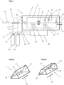
- FIG. 2a and 2b Possible shapes for integral and self-supporting structural units 2, 2.1 are shown in a simplified schematic.
- the end faces 20, 21 are triangle-like and parallelogram-like 20.1, 21.1. In both cases, this also includes surfaces with curved edges or with protuberances or indentations, as already described.
- the purpose of the shape is that the fuel system 1, 1.1 can be arranged between the cylindrical pressure tanks in a space-saving manner.
- the fastening options 22 are also shown on each of the side surfaces of the structural unit 2, 2.1. Using the fastening options 22, the fuel system 1, 1.1 can be mounted on a support structure that supports the pressure tanks and is attached to the vehicle.
- other similar shapes are conceivable that are suitable so that the fuel system can be arranged in the gaps between the pressure tanks without requiring additional space.
- the Fig.3 shows a further embodiment of the fuel system 1a according to the invention.
- the variant shown differs from that in Fig.1 shown embodiment in that the distributor 19 to the tank lines 8, 9 and the at least one check valve 16 are additionally arranged as internal components on the structural unit 2a. This means that there are even fewer interfaces that must be observed and checked during vehicle assembly.
- the tank nozzle 7 can be attached directly to the structural unit 2a and carried by it.
- the temperature sensor 34 and/or the pressure sensor 33 can advantageously also be positioned on the distributor 19 in this embodiment.
- the housing 5 can be manufactured as a base body for the sub-unit, in particular as an aluminum die-cast component, in which the necessary valve seats, openings or cavities for the sensors, as well as the gas lines, for example as flow-optimized channels, are incorporated. If it is designed in several parts, it is important that there are no free pipes between the parts are intended. Rather, the parts are connected directly to one another, for example by screwing.
Landscapes
- Engineering & Computer Science (AREA)
- Chemical & Material Sciences (AREA)
- Mechanical Engineering (AREA)
- Combustion & Propulsion (AREA)
- General Engineering & Computer Science (AREA)
- General Chemical & Material Sciences (AREA)
- Oil, Petroleum & Natural Gas (AREA)
- Chemical Kinetics & Catalysis (AREA)
- Life Sciences & Earth Sciences (AREA)
- Sustainable Development (AREA)
- Sustainable Energy (AREA)
- Transportation (AREA)
- Filling Or Discharging Of Gas Storage Vessels (AREA)
- Cooling, Air Intake And Gas Exhaust, And Fuel Tank Arrangements In Propulsion Units (AREA)
Description
- Die Erfindung betrifft ein Kraftstoffsystem zum Einbau in einem Wasserstoff-betriebenen Fahrzeug vorgesehen und für einen oder mehrere Wasserstoff-Drucktanks, auf Hochdruck-Niveau mit mindestens 200 bar ausgelegt, wobei das Kraftstoffsystem einen Anschluss für eine Eingangsleitung, einen Anschluss für eine Ausgangsleitung und einen Druckminderer umfasst. Und wobei der Druckminderer so ausgeführt ist, dass er den Druck des Wasserstoffs vom Hochdruck-Niveau aus dem Drucktank auf ein Mitteldruck-Niveau zwischen 3 bar und 30 bar reduzieren kann.
- Wasserstoff-betriebene Fahrzeuge haben beispielsweise einen Gasmotor oder eine Brennstoffzelle mit Elektromotor als Antrieb. Um ausreichend Treibstoff speichern zu können, wird der Wasserstoff unter hohem Druck im Tank gespeichert. Typisch für solche Drucktanks sind Drücke von über 200 bar, oftmals 350 bar oder 700 bar und teilweise sogar bis 875 bar. Da der Gasmotor oder die Brennstoffzelle bei niedrigerem Eingangsdruck betrieben wird, muss der Druck zuverlässig vom Hochdruck-Niveau auf ein Niederdruck-Niveau geregelt werden.
- Im Stand der Technik sind Kraftstoffsysteme für Wasserstoff-Drucktanks und zum Einbau in einem Wasserstoff-betriebenen Fahrzeuge bekannt. Solche werden beispielsweise in der
DE 102019200459 A1 , in derWO 2020/079329 A1 , in derFR 2 985 783 A1 DE 102017214184 A1 beschrieben. Mit einem Druckminderer wird das Druckniveau vom Tankdruck auf das geforderte niedrigere Druckniveau für eine Brennstoffzelle reduziert. Über eine Steuereinrichtung und einen Drucksensor am Drucktank kann gegebenenfalls der Füllstand bestimmt und mit einer Tankstelle kommuniziert werden. Darüber hinaus weist das Kraftstoffsystem Absperrventile und Rohrleitungen auf, die über entsprechende Verschraubungen verbunden werden. Werden mehrerer Drucktanks parallel angeschlossen, so kommen noch Verteilerstellen für die verschiedenen Tankleitungen dazu. All diese Komponenten und Verbindungsstellen müssen nach dem Einbau getestet und geprüft werden. Das verursacht erheblichen Aufwand und birgt Risiken in Bezug auf fehlerhafte Montage und entsprechende Undichtigkeit. - Die Aufgabe der Erfindung ist es nun, ein Kraftstoffsystem für ein Wasserstoff-betriebenes Fahrzeug weiterzuentwickeln und zu verbessern, so dass es zuverlässig und sicher betrieben werden kann und schnell und fehlerfrei montiert werden kann.
- Die Aufgabe wird durch ein Kraftstoffsystem gemäß Anspruch 1 gelöst. Weitere vorteilhafte Merkmale sind in den abhängigen Ansprüchen genannt.
- Erfindungsgemäß zeichnet sich das Kraftstoffsystem nach Anspruch 1 dadurch aus, dass es zumindest folgende interne Komponenten umfasst:
Einen Druckminderer, einen Gasfilter, ein Absperrventil, ein Entlüftungsventil, ein Überdruck-Sicherheitsventil und einen Drucksensor, wobei der Druckminderer als zweistufiger Druckminderer ausgeführt ist, derart dass dieser in der ersten Stufe den Druck aus dem Drucktank auf ein Zwischen-Niveau zwischen 40 und 80 bar reduziert und in der zweiten Stufe den Druck weiter auf das Mitteldruck-Niveau reduziert, und wobei die internen Komponenten und Gasleitungen, die diese internen Komponenten miteinander verbinden, in einer integralen und in sich tragenden Baueinheit angeordnet sind. - Besonders bevorzugt liegt das Mitteldruck-Niveau zwischen 10 und 25 bar. Durch einen zweistufigen Druckminderer ist eine genauere Druckeinstellung möglich.
- Um das Kraftstoffsystem zuverlässiger und sicherer im Betrieb zu machen, umfasst es neben dem Druckminderer noch weitere Komponenten. Ein Entlüftungsventil, über welches das System gespült werden kann, zum Beispiel nach Wartungsarbeiten. Einen Gasfilter, der kleinere Verunreinigungen aus den Drucktanks zurückhält und so für einen hochreinen Wasserstoff sorgt, wie er für eine längere Lebensdauer einer Brennstoffzelle nötig ist. Ein Absperrventil, mit dem das Kraftstoffsystem gegenüber der Brennstoffzelle oder dem Gasmotor abgesperrt werden kann. Ein Überdruck-Sicherheitsventil, das das Kraftstoffsystem gegen zu hohe Drücke absichert und welches bevorzugt in Durchflussrichtung nach dem Druckminderer angeordnet ist. Ein Drucksensor zur Messung des Zustandes des Wasserstoff-Gases. Aus diesen Messwerten kann - gegebenenfalls zusammen mit Messwerten von Sensoren am Drucktank - zuverlässiger und genauer bestimmt werden, wie viel Wasserstoff im Drucktank vorhanden ist. Das ist eine wichtige Information für die Berechnung der Reichweite eines Fahrzeugs und für den Tankvorgang.
- Zudem sind alle internen Komponenten, sowie entsprechende Gasleitungen, die die internen Komponenten miteinander verbinden, in einer integralen und in sich tragenden Baueinheit angeordnet. Das bietet den Vorteil, dass das erfindungsgemäße Kraftstoffsystem unabhängig vom Fahrzeug und unabhängig vom Drucktank als eine Baugruppe vormontiert werden kann. Dieses als Baugruppe vormontierte Kraftstoffsystem kann dann auch vorab getestet und sicherheitstechnisch und qualitätstechnisch abgenommen werden. Dadurch kann das Kraftstoffsystem erstmalig als abgeschlossene Baugruppe angeboten werden. Der Einbau im Fahrzeug ist weniger aufwändig, da nur noch wenige Anschlüsse verbunden werden müssen und alle internen Komponenten und Verbindungen bereits auf Funktion und Undichtigkeit getestet sind. Die Befestigung ist einfacher, da die in sich tragende Baueinheit nur wenige Befestigungspunkte benötigt und als eine Baugruppe montiert werden kann. Zudem wird die Anzahl der Verschraubungen im gesamten Kraftstoffsystem erheblich reduziert.
- Die integrale, in sich selbst tragende Baueinheit kann bevorzugt ganz oder teilweise mit einem Aluminium-Druckguss-Gehäuse ausgeführt sein. Darin können zum Beispiel Ventilsitze und/oder Kanäle als Gasleitungen integriert werden. Die zur Ventilmontage oder zur Montage anderer Komponenten notwendigen Öffnungen oder Hohlräume können mit Dichtungen und Deckeln verschlossen werden. Die integrale, in sich selbst tragende Baueinheit kann auch aus mehreren Teilen zusammengesetzt sein. Beispielsweise kann eine Teileinheit mit einem Aluminium-Druckguss-Gehäuse ausgeführt werden und weitere Komponenten sind an dieser Teileinheit befestigt. Erfindungsgemäß gibt es allerdings keine verschraubten, frei liegenden Rohrleitungen zwischen den Teilen oder den Komponenten, um die Zuverlässigkeit und einfache Montage nicht zu beeinträchtigen.
- In einer weiteren erfindungsgemäßen Ausführung umfasst das Kraftstoffsystem als interne Komponenten noch ein zweites Entlüftungsventil, wobei bevorzugt beide Entlüftungsventile mit einer gemeinsamen Spülleitung verbunden sind, welche durch das Gehäuse nach außen führt. Insbesondere ist das eine Entlüftungsventil vor dem Druckminderer und das andere Entlüftungsventil nach dem Druckminderer angeordnet. So kann sowohl die Hochdruckseite als auch die Mitteldruckseite zuverlässig gespült werden. Zudem können auch noch weitere Entlüftungsventile vorgesehen werden, insbesondere bei Verwendung eines zweistufigen Druckminderer.
- Weiterhin ist es von Vorteil, wenn als interne Komponenten zumindest ein Rückschlagventil und eine Verteilung auf mehrere Tankleitungen vorhanden sind, wobei die Tankleitungen nach außen führen und wobei für jeden Drucktank ein Anschluss vorhanden ist. Durch die zusätzliche Integration der Verteilung und des Rückschlagventils auf der Eingangsseite in die Baueinheit und damit in die Baugruppe des Kraftstoffsystems wird der Montage- und Testaufwand am Fahrzeug noch weiter reduziert. Der größte Teil der Verbindungsstellen und Verschraubungen ist somit intern im Kraftstoffsystem angeordnet und bereits vorab montiert und vorab getestet worden, wenn die Baugruppe im Fahrzeug eingebaut wird. Darüber hinaus ist es von Vorteil, wenn an der Eingangsleitung direkt der Tankstutzen angeschlossen ist und somit ein Teil des Kraftstoffsystems ist. Dadurch wird die Montage im Fahrzeug noch weiter vereinfacht.
- Bevorzugt ist der Druckminderer über eine Federbelastung auf das jeweilige, gewünschte Druckniveau einstellbar.
- Um zu große Temperaturänderungen bei höheren Volumenströmen durch das Kraftstoffsystem und bei starken Druckänderungen zu vermeiden, kann es von Vorteil sein, wenn am Druckminderer eine Kühleinrichtung vorgesehen ist. Die Kühleinrichtung kann bevorzugt als Wärmetauscher mit fluiddurchströmten Kanälen ausgeführt sein. Diese Kanäle können im gemeinsamen Gehäuse vorgesehen oder in dieses eingearbeitet sein. Insbesondere kann dieser Wärmetauscher so ausgeführt sein, dass er mit einem Kühlmittelsystem des Fahrzeuges verbindbar ist.
- In einer bevorzugten Ausführung umfasst das Kraftstoffsystem zusätzlich eine elektronische Tanksteuereinheit, welche an der Baueinheit befestigt und von dieser getragen ist, wobei die Tanksteuereinheit geeignet ist, zumindest die Signale der am Kraftstoffsystem vorhandenen Sensoren zu empfangen und zu verarbeiten und eines oder mehrere Ausgangssignale zu erzeugen. Durch die Integration des Kraftstoffsystems der elektronischen Tanksteuereinheit in das Kraftstoffsystem kann die Baugruppe noch umfangreicher vorab getestet werden und es sind noch weniger Schnittstellen bei der Montage im Fahrzeug zu beachten. Der Kabelbaum zwischen Tanksteuereinheit und den Sensoren in der Baueinheit kann somit auch integriert und von der Baueinheit getragen werden.
- Weiter verbessert wird die Tanksteuereinheit, wenn sie so eingerichtet ist, dass sie von jedem Drucktank ein Temperatursensorsignal empfangen kann und insbesondere, wenn sie von jedem Drucktank auch noch ein Drucksensorsignal empfangen kann. Damit kann die Berechnung des Füllstandes der Drucktanks genauer und zuverlässiger erfolgen.
- Zusätzlich kann die Tanksteuereinheit so eingerichtet sein, dass sie mit einer Wasserstoff-Tankstelle kommunizieren kann und insbesondere einen Tankvorgang steuern kann.
- In einer besonders bevorzugten Ausführung ist als interne Komponente ein Temperatursensor vorhanden. Mit dem Temperatursensor kann der Zustand des Wasserstoffs überwacht werden und unter bestimmten Bedingungen die Wasserstoffmenge berechnet werden.
- Insbesondere kann eine vereinfachte Ausführung Vorteile bieten, da sie kostengünstiger ist und weniger Komponenten enthält. Bei dieser erfindungsgemäßen Ausführung umfasst das Kraftstoffsystem als interne Sensoren nur genau einen Drucksensor und genau einen Temperatursensor, jeweils vor dem Druckminderer angeordnet.
- In einer weiteren vorteilhaften Ausführung sind als interne Komponenten noch ein zweiter Drucksensor und/oder noch ein zweiter Temperatursensor vorhanden sind, wobei bevorzugt ein Drucksensor und ein Temperatursensor vor dem Druckminderer und ein Drucksensor und ein Temperatursensor nach dem Druckminderer angeordnet sind. Durch diese zusätzlichen Sensoren wird die Bestimmung der Zustände des durchströmenden Wasserstoff-Gases genauer erfasst und somit die Berechnung der Wasserstoffmengen genauer und zuverlässiger. Zudem können Fehlfunktionen oder Undichtigkeiten besser erkannt werden, was die Sicherheit des Systems erhöht.
- Als Erweiterung kann als interne Komponente noch ein Wasserstoff-Reinheitssensor vorgesehen werden. Bevorzugt wird dieser in Durchflussrichtung nach dem Druckminderer angeordnet. Mit diesem zusätzlichen Sensor kann gewährleistet werden, dass zum Beispiel eine nachfolgende Brennstoffzelle ausreichend sauberen Wasserstoff zugeführt bekommt und somit die Funktion der Brennstoffzelle erhalten und ihre Lebensdauer verlängert wird. Eine notwendige Wartung oder ein notwendiger Austausch des Gasfilters wird rechtzeitig erkannt.
- Besonders bevorzugt sind die internen Komponenten in Durchflussrichtung in folgender Reihenfolge von der Eingangsleitung bis zur Ausgangsleitung angeordnet: Gasfilter, Druckminderer, Entlüftungsventil, Überdruck-Sicherheitsventil, Absperrventil. Weitere vorhandene interne Komponenten können zwischen diesen Komponenten oder vor diesen oder danach angeordnet sein. Die genannte Reihenfolge bietet eine besonders gute Funktionalität.
- Ebenso wird eine Ausführung von Erfindung umfasst, bei der die Baueinheit aus mehreren Teileinheiten zusammengesetzt ist, die so aneinander befestigt sind, dass sie die in sich tragende Baueinheit bilden.
- Insbesondere kann die Baueinheit eine Teileinheit umfassen, welche ein Gehäuse, bevorzugt aus einem Alu-Guss-Werkstoff, aufweist, in welchem zumindest die folgenden internen Komponenten angeordnet sind: der Druckminderer, der Drucksensor, das Entlüftungsventil, das Überdruck-Sicherheitsventil und das Absperrventil. Dabei ist in diesem Zusammenhang mit "angeordnet" gemeint, dass bei den Ventilen und ganz besonders beim Absperrventil es ausreichend ist, wenn zumindest der Ventilsitz in der Teileinheit angeordnet ist.
- Weiterhin ist es von Vorteil, wenn die Baueinheit eine im Wesentlichen prismaförmige Gestalt mit zwei Stirnseiten aufweist, wobei die Stirnseiten bevorzugt dreiecksähnlich oder bevorzugt Parallelogramm-ähnlich ausgeführt sind. Durch diese Form der Baueinheit lässt sich das Kraftstoffsystem platzsparend zwischen den Drucktanks am Fahrzeug unterbringen. Die Drucktanks sind langgestreckt und zylinderförmig, so dass die Baueinheit mit seiner dreiecksähnlichen oder Parallelogramm-ähnlichen Querschnittsform sehr gut in den Lücken zwischen den Drucktanks angeordnet werden kann, ohne zusätzlichen Bauraum zu benötigen.
- Unter dreiecksähnlicher Stirnseite wird in diesem Zusammenhang neben einem exakten Dreieck auch verstanden, wenn die Begrenzungslinien des Dreiecks leicht bogenförmig oder mit einzelnen Ausstülpungen oder Einbuchtungen ausgeführt sind. Entscheidend ist in diesem Zusammenhang, dass die Stirnseiten im Wesentlichen einer Dreiecksform ähneln. Gleiches gilt analog für die Parallelogramm-ähnlichen Stirnseiten.
- Insbesondere ist es vorteilhaft, dass der Anschluss für die Eingangsleitung und/oder der Anschluss für die Ausgangsleitung jeweils auf einer der Stirnseiten angeordnet sind. Dadurch sind sie gut zugänglich und können einfach montiert und auch gewartet werden.
- Um eine weiter vereinfachte Montage zu ermöglichen, ist es vorteilhaft, wenn die Baueinheit Befestigungsmöglichkeiten aufweist, über die das Kraftstoffsystem an einer Tragstruktur, die die Drucktanks im Fahrzeug befestigt, montiert werden kann. Somit kann gegebenenfalls das Kraftstoffsystem an einem Tankmodul, das eine Tragstruktur und mehrere Drucktanks umfasst, befestigt werden und mit den Tankleitungen der Drucktanks bereits vorab verbunden werden. Das Tankmodul inklusive Kraftstoffsystem wird dann als eine Gesamteinheit im Fahrzeug verbaut.
- Die Montagezeit in der Fertigungslinie der Fahrzeug-Hersteller ist somit weiter minimiert, was einen großen Vorteil darstellt.
- Anhand von Ausführungsbeispielen werden weitere vorteilhafte Merkmale der Erfindung erläutert unter Bezugnahme auf die Zeichnungen. Die genannten Merkmale können nicht nur in der dargestellten Kombination vorteilhaft umgesetzt werden, sondern auch einzeln untereinander kombiniert werden. Die Figuren zeigen im Einzelnen:
- Fig.1
- Schematische Darstellung eines erfindungsgemäßen Kraftstoffsystems
- Fig.2a,b
- Beispiele für die geometrische Form des Gehäuses
- Fig.3
- weiteres erfindungsgemäßes Kraftstoffsystem
- Nachfolgend werden die Figuren detaillierter beschrieben. Gleiche Bezugszahlen bezeichnen gleiche beziehungsweise analoge Bauteile oder Komponenten.
- Die
Fig.1 zeigt schematisch eine erfindungsgemäße Ausführung eines Kraftstoffsystems 1 für ein Wasserstoff-betriebenes Fahrzeug. Die Größenverhältnisse und die Position in Bezug auf die Drucktanks 40,50 sind nicht maßstäblich. Das Kraftstoffsystem 1 ist in dieser Ausführung über die Eingangsleitung 3 an den Verteiler 19 angeschlossen, der zum einen die Tankleitungen 8,9 und zum anderen den Tankstutzen 7 mit dem Kraftstoffsystem 1 verbindet. Dargestellt sind exemplarisch nur zwei Drucktanks 40,50, es können aber auch mehrere Drucktanks angeschlossen werden. - Als interne Komponenten sind der Druckminderer 10, der zweistufig ausgebildet ist, der Gasfilter 11, das Entlüftungsventil 13, sowie das Überdruck-Sicherheitsventil 14 und das Absperrventil 15 vor der Ausgangsleitung 4 vorhanden. All diese internen Komponenten sind in oder an der integralen und in sich tragenden Baueinheit 2 eingebaut. Die Durchflussrichtung von der Eingangsleitung 3 zur Ausgangsleitung 4 ist mit 18 bezeichnet. An die Ausgangsleitung 4 kann ein Verbraucher, wie zum Beispiel eine Brennstoffzelle oder ein Gasmotor angeschlossen werden. Des Weiteren ist zumindest ein Drucksensor 31,33 und zumindest ein Temperatursensor 32,34 als interne Komponente vorhanden.
- Durch die Verwendung der genannten internen Komponenten und die Integration in eine Baueinheit 2 wird das Kraftstoffsystem zuverlässiger. Das Kraftstoffsystem 1 als Baueinheit 2 kann vorab montiert und auf Funktion und Dichtigkeit getestet werden, so dass es bei der Fahrzeugmontage als eine Baugruppe mit wenigen Schnittstellen sehr viel schneller und zuverlässiger als bei bisherigen Kraftstoffsystemen montiert werden kann. Zudem müssen dann auch nur noch diese wenigen Schnittstellen auf Dichtigkeit geprüft werden.
- Mehrere der internen Komponenten können wie hier dargestellt in einem Gehäuse als Teileinheit angeordnet sein. Die weiteren Komponenten oder Teileinheiten sind so mit dieser Teileinheit verbunden, dass sie die Baueinheit 2 bilden. Das Gehäuse 5 der Teileinheit ist bevorzugt aus einem Alu-Guss-Material hergestellt. In der dargestellten Ausführung umfasst diese Teileinheit den Druckminderer 10, das Entlüftungsventil 13, das Überdruck-Sicherheitsventil 14 und das Absperrventil 15. Und optional Druck- und Temperatursensoren sowie gegebenenfalls die Kühleinrichtung 17, soweit vorgesehen. Insbesondere kann das Gehäuse 5 als Grundkörper der Teileinheit ausgeführt werden, in welchen die nötigen Ventilsitze, Öffnungen oder Hohlräume für die Sensoren, sowie die Gasleitungen, zum Beispiel als strömungsoptimierte Kanäle, eingearbeitet sind.
- Das Absperrventil 15 ist bevorzugt als elektromagnetisches Ventil ausgeführt. Der Druckminderer 10 zweistufig und bevorzugt federbelastet auf die gewünschten Druckniveaus eingestellt. Das Entlüftungsventil 13 hat eine Spülleitung, die durch das Gehäuse nach außen führt. In der Zeichnung bei Ventil 13 nur angedeutet. Das Entlüftungsventil 13 ist bevorzugt als manuelles Ventil ausgeführt, da es nur bei Inbetriebnahme oder Wartungsarbeiten benötigt wird.
- Das Überdruck-Sicherheitsventil 15 sichert die Mitteldruck-Seite des Kraftstoffsystems, also den Bereich in Durchflussrichtung nach dem Druckminderer 10, gegen zu hohe Drücke ab. Es führt in eine Abblasleitung 6, die nach außen geht und an die außerhalb ein Schlauch oder eine weitere Leitung angeschlossen werden kann, zur sicheren Abführung des Wasserstoff-Gases im Notfall.
- Zusätzlich ist optional in dieser Ausführung die elektronische Tanksteuereinheit 30 vorgesehen, welche an der Baueinheit 2 befestigt sein kann. Alternativ kann die Tanksteuereinheit auch als interne Komponente in der Baueinheit 2 angeordnet werden. Die Tanksteuereinheit 30 verarbeitet die Signale der internen Sensoren und zusätzlich die Signale der externen Sensoren, hier beispielsweise die der Drucksensoren 43, etc. und die der Temperatursensoren 42, etc. an den einzelnen Drucktanks 40,50. Damit ist eine zuverlässige Berechnung der Tankfüllstände und der Wasserstoffverbräuche möglich. Die Tanksteuereinheit 30 kann als Ausgangssignal beispielsweise die Tankfüllstände, eine Reichweite oder ähnliches ausgeben. Zudem kann sie gegebenenfalls mit einer Wasserstoff-Tankstelle kommunizieren, so dass der Tankvorgang optimal abläuft, oder sie kann den Tankvorgang in Kommunikation mit der Tankstelle steuern. Und die Tanksteuereinheit ist mit einer Brennstoffzelle oder einem Gasmotor verbunden, um Informationen und Signale auszutauschen.
- Zusätzlich können ein zweiter Drucksensor 31,33 und/oder ein zweiter Temperatursensor 32,34 als interne Komponente, wie dargestellt, eingebaut sein. Damit werden die Berechnungen der Tankfüllstände, die Kommunikation mit einer Tankstelle und die Überwachung der Dichtigkeit sowie die Erkennung von Fehlfunktionen weiter verbessert.
- Im Bereich des Druckminderer 10 kann eine Kühleinrichtung 17 vorgesehen sein, die dazu dient, zu starke Temperaturänderungen aufgrund der Druckentspannung des Wasserstoffs am Druckminderer 10 zu vermeiden.
- Bevorzugt sind die Eingangsleitung 3 und die Ausgangsleitung 4 an gegenüberliegenden Stirnseiten 20, 21 des Gehäuses 2 vorgesehen. Das führt dazu, dass das Kraftstoffsystem 1 schlank ausgeführt werden kann und dass die Anschlüsse für den Tankstutzen 7 und zur Brennstoffzelle oder zum Gasmotor genug Platz haben.
- In den
Fig. 2a und 2b sind mögliche Formen für integrale und in sich tragende Baueinheit 2, 2.1 schematisch vereinfacht dargestellt. Die Stirnflächen 20, 21 sind einmal dreiecks-ähnlich und einmal Parallelogramm-ähnlich 20.1, 21.1. In beiden Fällen sind darunter auch Flächen mit gebogenen Kanten oder mit Ausstülpungen oder Einbuchtungen zu verstehen, wie zuvor bereits beschrieben. Der Sinn der Formgebung ist, dass das Kraftstoffsystem 1, 1.1 platzsparend zwischen den zylinderförmigen Drucktanks angeordnet werden kann. Gezeigt sind auch die Befestigungsmöglichkeiten 22 jeweils auf einer der Seitenflächen der Baueinheit 2, 2.1. Über die Befestigungsmöglichkeiten 22 kann das Kraftstoffsystem 1, 1.1 an einer Tragstruktur montiert werden, die die Drucktanks trägt und am Fahrzeug befestigt ist. Über die gezeigten Baueinheit-Formen hinaus, sind weitere ähnliche Formen denkbar, die geeignet sind, so dass das Kraftstoffsystem in den Lücken zwischen den Drucktanks ohne zusätzlichen Platzbedarf angeordnet werden kann. - Die
Fig.3 zeigt eine weitere Ausführung des erfindungsgemäßen Kraftstoffsystems 1a. Die dargestellte Variante unterscheidet sich von der inFig.1 gezeigten Ausführung dadurch, dass zusätzlich der Verteiler 19 auf die Tankleitungen 8,9, sowie das zumindest eine Rückschlagventil 16 als interne Komponenten an der Baueinheit 2a angeordnet sind. Dadurch gibt es noch weniger Schnittstellen, die bei der Fahrzeugmontage beachtet und geprüft werden müssen. Insbesondere kann der Tankstutzen 7 direkt an der Baueinheit 2a befestigt sein und von dieser getragen werden. - Der Temperatursensor 34 und/oder der Drucksensor 33 können vorteilhafterweise in dieser Ausführung auch an dem Verteiler 19 positioniert sein.
- Als bevorzugte Ausführung kann das Gehäuse 5 als Grundkörper für die Teileinheit, insbesondere als Alu-Druckguss-Bauteil hergestellt werden, in welchen die nötigen Ventilsitze, Öffnungen oder Hohlräume für die Sensoren, sowie die Gasleitungen, zum Beispiel als strömungsoptimierte Kanäle, eingearbeitet sind. Wenn es mehrteilig ausgeführt ist, ist es wichtig, dass keine freien Rohrleitungen zwischen den Teilen vorgesehen sind. Sondern dass die Teile direkt miteinander verbunden, beispielsweise verschraubt werden.
- Exemplarisch sind wiederum nur zwei Drucktanks gezeigt. Auch hier können mehrere Tankleitungen und mehrere Drucktanks angeschlossen werden.
-
- 1, 1a, 1.1
- Kraftstoffsystem
- 2, 2a, 2.1
- integrale und in sich tragende Baueinheit
- 3, 3a
- Eingangsleitung
- 4
- Ausgangsleitung
- 5
- Gehäuse Teileinheit
- 6
- Abblasleitung
- 7
- Tankstutzen
- 8, 9
- Tankleitung
- 10
- Druckminderer
- 11
- Gasfilter
- 13
- Entlüftungsventil
- 14
- Überdruck-Sicherheitsventil
- 15
- Absperrventil
- 16
- Rückschlagventil
- 17
- Heizeinrichtung oder Kühleinrichtung
- 18
- Durchflussrichtung
- 19
- Verteiler
- 20, 20.1,21, 21.1
- Stirnseiten
- 22
- Befestigungsmöglichkeiten
- 30
- Tanksteuereinheit
- 31,33
- Drucksensor
- 32, 34
- Temperatursensor
- 40, 50
- Drucktank
- 41, 51
- Tankventil
- 42
- Temperatursensor
- 43
- Drucksensor
Claims (14)
- Kraftstoffsystem (1,1a,1.1) zum Einbau in einem Wasserstoff-betriebenen Fahrzeug und für einen oder mehrere Wasserstoff-Drucktanks (40,50), auf Hochdruck-Niveau mit mindestens 200 bar ausgelegt, umfassend einen Anschluss für eine Eingangsleitung (3,3a), einen Anschluss für eine Ausgangsleitung (4) und zumindest folgende interne Komponenten:Einen Druckminderer (10), einen Gasfilter (11), ein Absperrventil (15), ein Entlüftungsventil (13), ein Überdruck-Sicherheitsventil (14) und einen Drucksensor (31,33),wobei der Druckminderer (10) so ausgeführt ist, dass er den Druck des Wasserstoffs vom Hochdruck-Niveau aus dem Drucktank auf ein Mitteldruck-Niveau zwischen 3 bar und 30 bar reduzieren kann, indem der Druckminderer (10) als zweistufiger Druckminderer ausgeführt ist, wobei die erste Stufe den Druck aus dem Drucktank auf ein Zwischen-Niveau zwischen 40 und 80 bar reduziert und die zweite Stufe den Druck weiter auf das Mitteldruck-Niveau reduziert,und wobei die internen Komponenten und Gasleitungen, die diese internen Komponenten miteinander verbinden, in einer integralen und in sich tragenden Baueinheit (2,2a,2.1) angeordnet sind.
- Kraftstoffsystem (1,1a,1.1) nach Anspruch 1
dadurch gekennzeichnet,
dass es als interne Komponenten ein Rückschlagventil (16) und eine Verteilung (19) auf mehrere Tankleitungen (8,9) umfasst, wobei die Tankleitungen (8,9) aus der Baueinheit (2,2a,2.1) nach außen führen und für jeden Drucktank (40,50) ein Anschluss vorhanden ist. - Kraftstoffsystem (1,1a,1.1) nach einem der Ansprüche 1 oder 2
dadurch gekennzeichnet,
dass der Tankstutzen 7 ein Teil der Baueinheit (2,2a,2.1) ist. - Kraftstoffsystem (1,1a,1.1) nach einem der vorherigen Ansprüche
dadurch gekennzeichnet,
dass am Druckminderer (10) eine Kühleinrichtung (17) vorgesehen ist. - Kraftstoffsystem (1,1a,1.1) nach einem der vorherigen Ansprüche
dadurch gekennzeichnet,
dass eine elektronische Tanksteuereinheit (30) vorhanden ist, welche an der Baueinheit (2,2a,2.1) befestigt und von dieser getragen ist, wobei die Tanksteuereinheit geeignet ist, die Signale der vorhandenen Sensoren zu empfangen und zu verarbeiten und eines oder mehrere Ausgangssignale zu erzeugen. - Kraftstoffsystem (1,1a,1.1) nach Anspruch 5
dadurch gekennzeichnet,
dass die Tanksteuereinheit (30) eingerichtet ist, von jedem Drucktank (40,50) ein Temperatursensorsignal zu empfangen und insbesondere von jedem Drucktank (40,50) ein Drucksensorsignal zu empfangen. - Kraftstoffsystem (1,1a,1.1) nach einem der Ansprüche 5 oder 6
dadurch gekennzeichnet,
dass die Tanksteuereinheit (30) so eingerichtet ist, dass sie mit einer Wasserstoff-Tankstelle kommunizieren kann und insbesondere einen Tankvorgang steuern kann. - Kraftstoffsystem (1,1a,1.1) nach einem der vorherigen Ansprüche
dadurch gekennzeichnet,
dass als interne Komponente ein Temperatursensor (32,34) vorhanden ist, wobei bevorzugt als interne Sensoren nur ein Drucksensor (33) und ein Temperatursensor (34), jeweils vor dem Druckminderer (10) angeordnet, vorhanden sind. - Kraftstoffsystem (1,1a,1.1) nach einem der vorherigen Ansprüche
dadurch gekennzeichnet,
dass es als interne Komponente noch einen zweiten Drucksensor (31,33) und/oder noch einen zweiten Temperatursensor (32,34) umfasst, wobei bevorzugt ein Drucksensor (33) und ein Temperatursensor (34) vor dem Druckminderer (10) und ein Drucksensor (31) und ein Temperatursensor (32) nach dem Druckminderer (10) angeordnet sind. - Kraftstoffsystem (1,1a,1.1) nach einem der vorherigen Ansprüche
dadurch gekennzeichnet,
dass es als interne Komponente einen Wasserstoff-Reinheitssensor umfasst. - Kraftstoffsystem (1,1a,1.1) nach einem der vorherigen Ansprüche
dadurch gekennzeichnet,
dass die internen Komponenten in Durchflussrichtung (18) in folgender Reihenfolge von der Eingangsleitung (3) bis zur Ausgangsleitung (4) angeordnet sind:
Gasfilter (11), Druckminderer (10), Entlüftungsventil (13), Sicherheitsventil (14), Absperrventil (15). - Kraftstoffsystem (1,1a,1.1) nach einem der vorherigen Ansprüche
dadurch gekennzeichnet,
dass die Baueinheit (2,2a,2.1) aus mehreren Teileinheiten zusammengesetzt ist, die so aneinander befestigt sind, dass sie eine in sich tragende Baueinheit bilden. - Kraftstoffsystem (1,1a,1.1) nach einem der vorherigen Ansprüche
dadurch gekennzeichnet,
dass die Baueinheit (2,2a,2.1) eine Teileinheit umfasst, welche ein Gehäuse 5, bevorzugt aus einem Alu-Guss-Werkstoff, aufweist, in welchem zumindest die folgenden internen Komponenten angeordnet sind: der Druckminderer (10), der Drucksensor (31,33), das Entlüftungsventil (13), das Überdruck-Sicherheitsventil (14) und das Absperrventil (15). - Kraftstoffsystem (1,1a,1.1) nach einem der vorherigen Ansprüche
dadurch gekennzeichnet,
dass die Baueinheit (2,2a,2.1) Befestigungsmöglichkeiten (22) aufweist, über die das Kraftstoffsystem (1,1a,1.1) an einer Tragstruktur, die die Drucktanks im Fahrzeug befestigt, montiert werden kann.
Applications Claiming Priority (2)
| Application Number | Priority Date | Filing Date | Title |
|---|---|---|---|
| DE102021116567.9A DE102021116567A1 (de) | 2021-06-28 | 2021-06-28 | Kraftstoffsystem für einen Drucktank und für ein gasbetriebenes Fahrzeug |
| PCT/EP2022/067471 WO2023274902A1 (de) | 2021-06-28 | 2022-06-27 | Kraftstoffsystem für einen drucktank und für ein gasbetriebenes fahrzeug |
Publications (2)
| Publication Number | Publication Date |
|---|---|
| EP4363759A1 EP4363759A1 (de) | 2024-05-08 |
| EP4363759B1 true EP4363759B1 (de) | 2025-03-05 |
Family
ID=82446434
Family Applications (1)
| Application Number | Title | Priority Date | Filing Date |
|---|---|---|---|
| EP22738418.7A Active EP4363759B1 (de) | 2021-06-28 | 2022-06-27 | Kraftstoffsystem für einen drucktank und für ein gasbetriebenes fahrzeug |
Country Status (5)
| Country | Link |
|---|---|
| US (1) | US20240300322A1 (de) |
| EP (1) | EP4363759B1 (de) |
| CN (1) | CN117581052A (de) |
| DE (1) | DE102021116567A1 (de) |
| WO (1) | WO2023274902A1 (de) |
Families Citing this family (11)
| Publication number | Priority date | Publication date | Assignee | Title |
|---|---|---|---|---|
| DE102022121886A1 (de) * | 2022-08-30 | 2024-02-29 | Voith Patent Gmbh | Kraftstoffsystem für einen Drucktank zum Einbau in ein gasbetriebenes Fahrzeug |
| DE102023200444A1 (de) * | 2023-01-20 | 2024-07-25 | Robert Bosch Gesellschaft mit beschränkter Haftung | Verfahren zum Betreiben einer Tankvorrichtung und Tankvorrichtung zum Speichern eines Gastreibstoffs |
| DE102023200439A1 (de) * | 2023-01-20 | 2024-07-25 | Robert Bosch Gesellschaft mit beschränkter Haftung | Verfahren zum Betreiben einer Tankvorrichtung zum Speichern eines Gastreibstoffs und Tankvorrichtung zum Speichern eines Gastreibstoffs |
| DE102023200443A1 (de) * | 2023-01-20 | 2024-07-25 | Robert Bosch Gesellschaft mit beschränkter Haftung | Verfahren zum Betreiben einer Tankvorrichtung zum Speichern eines Gastreibstoffs und Tankvorrichtung zum Speichern eines Gastreibstoffs |
| DE102023200440A1 (de) * | 2023-01-20 | 2024-07-25 | Robert Bosch Gesellschaft mit beschränkter Haftung | Verfahren zum Ermitteln des Tankfüllstands einer Tankvorrichtung und Tankvorrichtung zum Speichern eines Gastreibstoffs |
| CN116279816B (zh) * | 2023-03-10 | 2025-06-17 | 东风汽车股份有限公司 | 一种cng商用车燃气集成控制装置及cng商用车 |
| DE102023106161A1 (de) * | 2023-03-13 | 2024-09-19 | Voith Patent Gmbh | Kraftstoffsystem zum Einbau in ein gasbetriebenes Fahrzeug und Verfahren zur Steuerung eines solchen Kraftstoffsystems |
| DE102023109666A1 (de) * | 2023-04-18 | 2024-10-24 | Bayerische Motoren Werke Aktiengesellschaft | Versorgungssystem und Antriebssystem |
| DE102023114356A1 (de) * | 2023-06-01 | 2024-12-05 | Liebherr-Components Deggendorf Gmbh | Ventilblock zum Durchleiten und Konditionieren eines gasförmigen Kraftstoffs |
| DE102023117630A1 (de) * | 2023-07-04 | 2025-01-09 | Bayerische Motoren Werke Aktiengesellschaft | Verfahren und Vorrichtung zur Ermittlung des Drucks in einem Druckbehälter |
| DE102023208066A1 (de) * | 2023-08-23 | 2025-02-27 | Robert Bosch Gesellschaft mit beschränkter Haftung | Wasserstoffversorgungssystem für eine Brennkraftmaschine |
Family Cites Families (19)
| Publication number | Priority date | Publication date | Assignee | Title |
|---|---|---|---|---|
| KR20000061714A (ko) * | 1999-03-30 | 2000-10-25 | 박상록 | 일체식 2단계 가스압력 제어기 |
| DE20318684U1 (de) * | 2003-01-16 | 2004-03-11 | Braune, Mathias | Vorrichtung zur Gemischaufbereitung bei einem gasbetriebenen Kraftfahrzeug |
| FR2857632A1 (fr) * | 2003-07-18 | 2005-01-21 | Gie Psa Peugeot Citroen | Vehicule automobile avec reservoir de combustible gazeux et circuit d'alimentation basse pression |
| JP4716046B2 (ja) * | 2005-01-26 | 2011-07-06 | トヨタ自動車株式会社 | 燃料タンクシステム |
| DE102005016281B4 (de) | 2005-04-08 | 2010-01-14 | Continental Automotive Gmbh | Betriebsverfahren und Vorrichtung für eine gasbetriebene Brennkraftmaschine |
| ES2317482T3 (es) * | 2006-12-12 | 2009-04-16 | C.R.F. Societa Consortile Per Azioni | Unidad electronica reductora o reguladora de la presion para alimentar gas, en particular metano o hidrogeno a un motor de combustion interna, y sistema de alimentacion de gas que incluye esta unidad. |
| CN101354592A (zh) * | 2008-07-17 | 2009-01-28 | 朱成伟 | 一种气体减压器 |
| FR2985783B1 (fr) * | 2012-01-12 | 2013-12-20 | Cahouet | Dispositif vanne detendeur a detente prereglee et vehicule equipe d'un tel dispositif |
| JP6207477B2 (ja) * | 2014-07-03 | 2017-10-04 | 愛三工業株式会社 | 燃料供給ユニット |
| CN206816874U (zh) * | 2017-05-10 | 2017-12-29 | 上海瀚氢动力科技有限公司 | 适用于燃料电池电动汽车供氢系统的组合阀 |
| CN206817171U (zh) * | 2017-05-10 | 2017-12-29 | 上海瀚氢动力科技有限公司 | 适用于燃料电池电动汽车的车载供氢系统 |
| DE102017213521A1 (de) | 2017-08-03 | 2019-02-07 | Bayerische Motoren Werke Aktiengesellschaft | Ventil-Vorrichtung für einen Speicherbehälter |
| DE102017214184A1 (de) | 2017-08-15 | 2019-02-21 | Robert Bosch Gmbh | Anhänger mit einem Hochdrucktank zum Transport eines gasförmigen und/oder flüssigen Treibstoffs, System aus Anhänger und Zugfahrzeug, Verfahren zum Betanken des Hochdrucktanks sowie Steuereinrichtung |
| EP3867561B1 (de) * | 2018-10-18 | 2024-08-21 | Alcrys Fluid-Control & Services | Vorrichtung zum befüllen und entnehmen von gas |
| DE102019200459A1 (de) | 2019-01-16 | 2020-07-16 | Robert Bosch Gmbh | Brennstoffzellensystem |
| DE102019218343A1 (de) | 2019-11-27 | 2021-05-27 | Robert Bosch Gmbh | Haltevorrichtung zum sicheren Anordnen von Wasserstofftanks an einem Fahrzeug |
| CN212226673U (zh) * | 2020-05-08 | 2020-12-25 | 江西亚瑞科技有限责任公司 | 一种飞机发动机油封设备组件 |
| CN212298549U (zh) * | 2020-06-22 | 2021-01-05 | 如皋瀚氢新能源科技有限公司 | 一种集成式减压瓶阀 |
| CN116818018A (zh) * | 2023-07-05 | 2023-09-29 | 国网新疆电力有限公司电力科学研究院 | 一种少油设备三合一智能传感器 |
-
2021
- 2021-06-28 DE DE102021116567.9A patent/DE102021116567A1/de active Pending
-
2022
- 2022-06-27 US US18/574,882 patent/US20240300322A1/en active Pending
- 2022-06-27 CN CN202280045747.1A patent/CN117581052A/zh active Pending
- 2022-06-27 EP EP22738418.7A patent/EP4363759B1/de active Active
- 2022-06-27 WO PCT/EP2022/067471 patent/WO2023274902A1/de not_active Ceased
Also Published As
| Publication number | Publication date |
|---|---|
| US20240300322A1 (en) | 2024-09-12 |
| CN117581052A (zh) | 2024-02-20 |
| DE102021116567A1 (de) | 2022-12-29 |
| EP4363759A1 (de) | 2024-05-08 |
| WO2023274902A1 (de) | 2023-01-05 |
Similar Documents
| Publication | Publication Date | Title |
|---|---|---|
| EP4363759B1 (de) | Kraftstoffsystem für einen drucktank und für ein gasbetriebenes fahrzeug | |
| DE102011052658B4 (de) | Verfahren und System zum Kalibrieren eines Drucksensors in einem Gasspeichersystem | |
| DE102011111610B4 (de) | Kalibrierung von allen Druckwandlern in einem Wasserstoffspeichersystem | |
| DE112010005532B4 (de) | Brennstoffleckage-Erfassungssystem und Erfassungsverfahren | |
| WO2021156349A1 (de) | Druckbehälteranordnung und druckbehältersystem | |
| EP3006812B1 (de) | Elektronischer durchflusssensor | |
| DE102012104141A1 (de) | Verwendung eines Wasserstoffsensors zum Detektieren eines Wasserstoffspeichersystemdruckreglerausfalls | |
| WO2018001560A1 (de) | Tankventil | |
| DE102016008442A1 (de) | Tankventil | |
| EP1464932B1 (de) | Druckregler und Vorrichtung zur kontinuierlichen Messung eines dynamischen Flüssigkeitsverbrauchs | |
| WO2021104825A1 (de) | Haltevorrichtung zum sicheren anordnen von wasserstofftanks an einem fahrzeug | |
| EP2132473A1 (de) | Verfahren zur diagnose eines absperrventils | |
| DE102009049687A1 (de) | Gasbehälteranordnung und Verfahren zum Betreiben einer Gasbehälteranordnung | |
| DE102016214577A1 (de) | Druckbehältersystem umfassend mindestens einen ersten Druckbehälter und einen zweiten Druckbehälter zum Speichern eines Brennstoffs, insbesondere von Wasserstoff, für ein Fahrzeug | |
| EP3997424B1 (de) | Messsystem zur messung eines durchflusses | |
| DE102012018102A1 (de) | Verfahren zur Luftversorgung einer Brennstoffzelle | |
| DE102005048456A1 (de) | Verfahren zur Diagnose eines Absperrventils | |
| DE60013383T2 (de) | Fahrzeugtank für Flüssiggas | |
| DE102017127790A1 (de) | Brennstoffzellensystem ohne Hoher-Druck-Leitung eines Wasserstoffzuführsystems und Steuerungsverfahren davon | |
| DE102004005446A1 (de) | Mit Brennstoff betreibbare Vorrichtung zur Wandlung von Energie, insbesondere Brennstoffzellenvorrichtung | |
| EP0723628A1 (de) | Verfahren und anordnung zum überprüfen eines tankentlüftungssystems für ein kraftfahrzeug | |
| DE102022121886A1 (de) | Kraftstoffsystem für einen Drucktank zum Einbau in ein gasbetriebenes Fahrzeug | |
| DE102012018516A1 (de) | Vorrichtung zur Druckregelung | |
| EP4402402B1 (de) | System mit einem kryobehälter und einem einstückigen druckmanagementsystem | |
| DE202013004126U1 (de) | Gashandhabungseinheit |
Legal Events
| Date | Code | Title | Description |
|---|---|---|---|
| STAA | Information on the status of an ep patent application or granted ep patent |
Free format text: STATUS: UNKNOWN |
|
| STAA | Information on the status of an ep patent application or granted ep patent |
Free format text: STATUS: THE INTERNATIONAL PUBLICATION HAS BEEN MADE |
|
| PUAI | Public reference made under article 153(3) epc to a published international application that has entered the european phase |
Free format text: ORIGINAL CODE: 0009012 |
|
| STAA | Information on the status of an ep patent application or granted ep patent |
Free format text: STATUS: REQUEST FOR EXAMINATION WAS MADE |
|
| 17P | Request for examination filed |
Effective date: 20240129 |
|
| AK | Designated contracting states |
Kind code of ref document: A1 Designated state(s): AL AT BE BG CH CY CZ DE DK EE ES FI FR GB GR HR HU IE IS IT LI LT LU LV MC MK MT NL NO PL PT RO RS SE SI SK SM TR |
|
| DAV | Request for validation of the european patent (deleted) | ||
| DAX | Request for extension of the european patent (deleted) | ||
| GRAP | Despatch of communication of intention to grant a patent |
Free format text: ORIGINAL CODE: EPIDOSNIGR1 |
|
| STAA | Information on the status of an ep patent application or granted ep patent |
Free format text: STATUS: GRANT OF PATENT IS INTENDED |
|
| INTG | Intention to grant announced |
Effective date: 20241008 |
|
| GRAS | Grant fee paid |
Free format text: ORIGINAL CODE: EPIDOSNIGR3 |
|
| GRAA | (expected) grant |
Free format text: ORIGINAL CODE: 0009210 |
|
| STAA | Information on the status of an ep patent application or granted ep patent |
Free format text: STATUS: THE PATENT HAS BEEN GRANTED |
|
| AK | Designated contracting states |
Kind code of ref document: B1 Designated state(s): AL AT BE BG CH CY CZ DE DK EE ES FI FR GB GR HR HU IE IS IT LI LT LU LV MC MK MT NL NO PL PT RO RS SE SI SK SM TR |
|
| REG | Reference to a national code |
Ref country code: GB Ref legal event code: FG4D Free format text: NOT ENGLISH |
|
| REG | Reference to a national code |
Ref country code: CH Ref legal event code: EP |
|
| REG | Reference to a national code |
Ref country code: DE Ref legal event code: R096 Ref document number: 502022003114 Country of ref document: DE |
|
| REG | Reference to a national code |
Ref country code: IE Ref legal event code: FG4D Free format text: LANGUAGE OF EP DOCUMENT: GERMAN |
|
| REG | Reference to a national code |
Ref country code: DE Ref legal event code: R081 Ref document number: 502022003114 Country of ref document: DE Owner name: VOITH HYSTECH GMBH, DE Free format text: FORMER OWNER: VOITH PATENT GMBH, 89522 HEIDENHEIM, DE |
|
| RAP2 | Party data changed (patent owner data changed or rights of a patent transferred) |
Owner name: VOITH HYSTECH GMBH |
|
| PG25 | Lapsed in a contracting state [announced via postgrant information from national office to epo] |
Ref country code: RS Free format text: LAPSE BECAUSE OF FAILURE TO SUBMIT A TRANSLATION OF THE DESCRIPTION OR TO PAY THE FEE WITHIN THE PRESCRIBED TIME-LIMIT Effective date: 20250605 |
|
| PG25 | Lapsed in a contracting state [announced via postgrant information from national office to epo] |
Ref country code: FI Free format text: LAPSE BECAUSE OF FAILURE TO SUBMIT A TRANSLATION OF THE DESCRIPTION OR TO PAY THE FEE WITHIN THE PRESCRIBED TIME-LIMIT Effective date: 20250305 |
|
| PGFP | Annual fee paid to national office [announced via postgrant information from national office to epo] |
Ref country code: DE Payment date: 20250618 Year of fee payment: 4 |
|
| REG | Reference to a national code |
Ref country code: NL Ref legal event code: MP Effective date: 20250305 |
|
| PG25 | Lapsed in a contracting state [announced via postgrant information from national office to epo] |
Ref country code: ES Free format text: LAPSE BECAUSE OF FAILURE TO SUBMIT A TRANSLATION OF THE DESCRIPTION OR TO PAY THE FEE WITHIN THE PRESCRIBED TIME-LIMIT Effective date: 20250305 |
|
| REG | Reference to a national code |
Ref country code: LT Ref legal event code: MG9D |
|
| PG25 | Lapsed in a contracting state [announced via postgrant information from national office to epo] |
Ref country code: NO Free format text: LAPSE BECAUSE OF FAILURE TO SUBMIT A TRANSLATION OF THE DESCRIPTION OR TO PAY THE FEE WITHIN THE PRESCRIBED TIME-LIMIT Effective date: 20250605 |
|
| PG25 | Lapsed in a contracting state [announced via postgrant information from national office to epo] |
Ref country code: HR Free format text: LAPSE BECAUSE OF FAILURE TO SUBMIT A TRANSLATION OF THE DESCRIPTION OR TO PAY THE FEE WITHIN THE PRESCRIBED TIME-LIMIT Effective date: 20250305 |
|
| PG25 | Lapsed in a contracting state [announced via postgrant information from national office to epo] |
Ref country code: LV Free format text: LAPSE BECAUSE OF FAILURE TO SUBMIT A TRANSLATION OF THE DESCRIPTION OR TO PAY THE FEE WITHIN THE PRESCRIBED TIME-LIMIT Effective date: 20250305 |
|
| PG25 | Lapsed in a contracting state [announced via postgrant information from national office to epo] |
Ref country code: GR Free format text: LAPSE BECAUSE OF FAILURE TO SUBMIT A TRANSLATION OF THE DESCRIPTION OR TO PAY THE FEE WITHIN THE PRESCRIBED TIME-LIMIT Effective date: 20250606 Ref country code: BG Free format text: LAPSE BECAUSE OF FAILURE TO SUBMIT A TRANSLATION OF THE DESCRIPTION OR TO PAY THE FEE WITHIN THE PRESCRIBED TIME-LIMIT Effective date: 20250305 |
|
| PGFP | Annual fee paid to national office [announced via postgrant information from national office to epo] |
Ref country code: AT Payment date: 20250721 Year of fee payment: 4 |
|
| PG25 | Lapsed in a contracting state [announced via postgrant information from national office to epo] |
Ref country code: NL Free format text: LAPSE BECAUSE OF FAILURE TO SUBMIT A TRANSLATION OF THE DESCRIPTION OR TO PAY THE FEE WITHIN THE PRESCRIBED TIME-LIMIT Effective date: 20250305 |
|
| PG25 | Lapsed in a contracting state [announced via postgrant information from national office to epo] |
Ref country code: SE Free format text: LAPSE BECAUSE OF FAILURE TO SUBMIT A TRANSLATION OF THE DESCRIPTION OR TO PAY THE FEE WITHIN THE PRESCRIBED TIME-LIMIT Effective date: 20250305 |
|
| PG25 | Lapsed in a contracting state [announced via postgrant information from national office to epo] |
Ref country code: SM Free format text: LAPSE BECAUSE OF FAILURE TO SUBMIT A TRANSLATION OF THE DESCRIPTION OR TO PAY THE FEE WITHIN THE PRESCRIBED TIME-LIMIT Effective date: 20250305 |
|
| PG25 | Lapsed in a contracting state [announced via postgrant information from national office to epo] |
Ref country code: PT Free format text: LAPSE BECAUSE OF FAILURE TO SUBMIT A TRANSLATION OF THE DESCRIPTION OR TO PAY THE FEE WITHIN THE PRESCRIBED TIME-LIMIT Effective date: 20250707 |
|
| PG25 | Lapsed in a contracting state [announced via postgrant information from national office to epo] |
Ref country code: PL Free format text: LAPSE BECAUSE OF FAILURE TO SUBMIT A TRANSLATION OF THE DESCRIPTION OR TO PAY THE FEE WITHIN THE PRESCRIBED TIME-LIMIT Effective date: 20250305 Ref country code: IT Free format text: LAPSE BECAUSE OF FAILURE TO SUBMIT A TRANSLATION OF THE DESCRIPTION OR TO PAY THE FEE WITHIN THE PRESCRIBED TIME-LIMIT Effective date: 20250305 |
|
| PG25 | Lapsed in a contracting state [announced via postgrant information from national office to epo] |
Ref country code: EE Free format text: LAPSE BECAUSE OF FAILURE TO SUBMIT A TRANSLATION OF THE DESCRIPTION OR TO PAY THE FEE WITHIN THE PRESCRIBED TIME-LIMIT Effective date: 20250305 Ref country code: CZ Free format text: LAPSE BECAUSE OF FAILURE TO SUBMIT A TRANSLATION OF THE DESCRIPTION OR TO PAY THE FEE WITHIN THE PRESCRIBED TIME-LIMIT Effective date: 20250305 |
|
| PG25 | Lapsed in a contracting state [announced via postgrant information from national office to epo] |
Ref country code: RO Free format text: LAPSE BECAUSE OF FAILURE TO SUBMIT A TRANSLATION OF THE DESCRIPTION OR TO PAY THE FEE WITHIN THE PRESCRIBED TIME-LIMIT Effective date: 20250305 |
|
| PG25 | Lapsed in a contracting state [announced via postgrant information from national office to epo] |
Ref country code: SK Free format text: LAPSE BECAUSE OF FAILURE TO SUBMIT A TRANSLATION OF THE DESCRIPTION OR TO PAY THE FEE WITHIN THE PRESCRIBED TIME-LIMIT Effective date: 20250305 |
|
| PG25 | Lapsed in a contracting state [announced via postgrant information from national office to epo] |
Ref country code: IS Free format text: LAPSE BECAUSE OF FAILURE TO SUBMIT A TRANSLATION OF THE DESCRIPTION OR TO PAY THE FEE WITHIN THE PRESCRIBED TIME-LIMIT Effective date: 20250705 |
|
| REG | Reference to a national code |
Ref country code: DE Ref legal event code: R097 Ref document number: 502022003114 Country of ref document: DE |
|
| PLBE | No opposition filed within time limit |
Free format text: ORIGINAL CODE: 0009261 |
|
| STAA | Information on the status of an ep patent application or granted ep patent |
Free format text: STATUS: NO OPPOSITION FILED WITHIN TIME LIMIT |
|
| PG25 | Lapsed in a contracting state [announced via postgrant information from national office to epo] |
Ref country code: DK Free format text: LAPSE BECAUSE OF FAILURE TO SUBMIT A TRANSLATION OF THE DESCRIPTION OR TO PAY THE FEE WITHIN THE PRESCRIBED TIME-LIMIT Effective date: 20250305 |
|
| REG | Reference to a national code |
Ref country code: CH Ref legal event code: L10 Free format text: ST27 STATUS EVENT CODE: U-0-0-L10-L00 (AS PROVIDED BY THE NATIONAL OFFICE) Effective date: 20260114 |
|
| REG | Reference to a national code |
Ref country code: CH Ref legal event code: H13 Free format text: ST27 STATUS EVENT CODE: U-0-0-H10-H13 (AS PROVIDED BY THE NATIONAL OFFICE) Effective date: 20260127 |
|
| PG25 | Lapsed in a contracting state [announced via postgrant information from national office to epo] |
Ref country code: MC Free format text: LAPSE BECAUSE OF FAILURE TO SUBMIT A TRANSLATION OF THE DESCRIPTION OR TO PAY THE FEE WITHIN THE PRESCRIBED TIME-LIMIT Effective date: 20250305 |
|
| 26N | No opposition filed |
Effective date: 20251208 |