EP4362592B1 - Radio transmission device and radio transmission method - Google Patents
Radio transmission device and radio transmission method Download PDFInfo
- Publication number
- EP4362592B1 EP4362592B1 EP24164180.2A EP24164180A EP4362592B1 EP 4362592 B1 EP4362592 B1 EP 4362592B1 EP 24164180 A EP24164180 A EP 24164180A EP 4362592 B1 EP4362592 B1 EP 4362592B1
- Authority
- EP
- European Patent Office
- Prior art keywords
- user data
- control information
- section
- size
- transmission format
- Prior art date
- Legal status (The legal status is an assumption and is not a legal conclusion. Google has not performed a legal analysis and makes no representation as to the accuracy of the status listed.)
- Active
Links
Images


Classifications
-
- H—ELECTRICITY
- H04—ELECTRIC COMMUNICATION TECHNIQUE
- H04W—WIRELESS COMMUNICATION NETWORKS
- H04W72/00—Local resource management
- H04W72/20—Control channels or signalling for resource management
-
- H—ELECTRICITY
- H04—ELECTRIC COMMUNICATION TECHNIQUE
- H04L—TRANSMISSION OF DIGITAL INFORMATION, e.g. TELEGRAPHIC COMMUNICATION
- H04L1/00—Arrangements for detecting or preventing errors in the information received
- H04L1/0001—Systems modifying transmission characteristics according to link quality, e.g. power backoff
- H04L1/0009—Systems modifying transmission characteristics according to link quality, e.g. power backoff by adapting the channel coding
- H04L1/0013—Rate matching, e.g. puncturing or repetition of code symbols
-
- H—ELECTRICITY
- H04—ELECTRIC COMMUNICATION TECHNIQUE
- H04L—TRANSMISSION OF DIGITAL INFORMATION, e.g. TELEGRAPHIC COMMUNICATION
- H04L1/00—Arrangements for detecting or preventing errors in the information received
- H04L1/0001—Systems modifying transmission characteristics according to link quality, e.g. power backoff
- H04L1/0023—Systems modifying transmission characteristics according to link quality, e.g. power backoff characterised by the signalling
- H04L1/0025—Transmission of mode-switching indication
-
- H—ELECTRICITY
- H04—ELECTRIC COMMUNICATION TECHNIQUE
- H04L—TRANSMISSION OF DIGITAL INFORMATION, e.g. TELEGRAPHIC COMMUNICATION
- H04L1/00—Arrangements for detecting or preventing errors in the information received
- H04L1/0001—Systems modifying transmission characteristics according to link quality, e.g. power backoff
- H04L1/0023—Systems modifying transmission characteristics according to link quality, e.g. power backoff characterised by the signalling
- H04L1/0026—Transmission of channel quality indication
-
- H—ELECTRICITY
- H04—ELECTRIC COMMUNICATION TECHNIQUE
- H04L—TRANSMISSION OF DIGITAL INFORMATION, e.g. TELEGRAPHIC COMMUNICATION
- H04L1/00—Arrangements for detecting or preventing errors in the information received
- H04L1/0001—Systems modifying transmission characteristics according to link quality, e.g. power backoff
- H04L1/0023—Systems modifying transmission characteristics according to link quality, e.g. power backoff characterised by the signalling
- H04L1/0028—Formatting
- H04L1/0029—Reduction of the amount of signalling, e.g. retention of useful signalling or differential signalling
-
- H—ELECTRICITY
- H04—ELECTRIC COMMUNICATION TECHNIQUE
- H04L—TRANSMISSION OF DIGITAL INFORMATION, e.g. TELEGRAPHIC COMMUNICATION
- H04L1/00—Arrangements for detecting or preventing errors in the information received
- H04L1/12—Arrangements for detecting or preventing errors in the information received by using return channel
- H04L1/16—Arrangements for detecting or preventing errors in the information received by using return channel in which the return channel carries supervisory signals, e.g. repetition request signals
- H04L1/1607—Details of the supervisory signal
-
- H—ELECTRICITY
- H04—ELECTRIC COMMUNICATION TECHNIQUE
- H04L—TRANSMISSION OF DIGITAL INFORMATION, e.g. TELEGRAPHIC COMMUNICATION
- H04L1/00—Arrangements for detecting or preventing errors in the information received
- H04L1/0001—Systems modifying transmission characteristics according to link quality, e.g. power backoff
- H04L1/0002—Systems modifying transmission characteristics according to link quality, e.g. power backoff by adapting the transmission rate
- H04L1/0003—Systems modifying transmission characteristics according to link quality, e.g. power backoff by adapting the transmission rate by switching between different modulation schemes
-
- H—ELECTRICITY
- H04—ELECTRIC COMMUNICATION TECHNIQUE
- H04L—TRANSMISSION OF DIGITAL INFORMATION, e.g. TELEGRAPHIC COMMUNICATION
- H04L1/00—Arrangements for detecting or preventing errors in the information received
- H04L1/0001—Systems modifying transmission characteristics according to link quality, e.g. power backoff
- H04L1/0006—Systems modifying transmission characteristics according to link quality, e.g. power backoff by adapting the transmission format
- H04L1/0007—Systems modifying transmission characteristics according to link quality, e.g. power backoff by adapting the transmission format by modifying the frame length
-
- H—ELECTRICITY
- H04—ELECTRIC COMMUNICATION TECHNIQUE
- H04L—TRANSMISSION OF DIGITAL INFORMATION, e.g. TELEGRAPHIC COMMUNICATION
- H04L1/00—Arrangements for detecting or preventing errors in the information received
- H04L1/12—Arrangements for detecting or preventing errors in the information received by using return channel
- H04L1/16—Arrangements for detecting or preventing errors in the information received by using return channel in which the return channel carries supervisory signals, e.g. repetition request signals
- H04L1/1607—Details of the supervisory signal
- H04L1/1671—Details of the supervisory signal the supervisory signal being transmitted together with control information
-
- H—ELECTRICITY
- H04—ELECTRIC COMMUNICATION TECHNIQUE
- H04W—WIRELESS COMMUNICATION NETWORKS
- H04W72/00—Local resource management
- H04W72/12—Wireless traffic scheduling
- H04W72/1263—Mapping of traffic onto schedule, e.g. scheduled allocation or multiplexing of flows
- H04W72/1268—Mapping of traffic onto schedule, e.g. scheduled allocation or multiplexing of flows of uplink data flows
Definitions
- the present disclosure relates to a mobile station and a communication method.
- TSG RAN The technical specification group radio access network (“TSG RAN") of the 3rd generation partnership project (“3GPP”) is currently conducting studies on a next-generation mobile communication system, referred to as long term evolution (“LTE").
- Working group 1 of the TSGRAN (“RAN 1”) is moving forward with the standardization of LTE radio access schemes.
- SC-FDMA single-carrier FDMA
- SC-FDMA single-carrier FDMA
- This SC-FDMA is has a characteristic of low PAPR (Peak to Average Power Ratio), and is suitable to the uplink where transmission power of a terminal is limited. Therefore, to transmit control information of layer 1 ("L1") or layer 2 ("L2") at the timing user data is transmitted while maintaining the low PAPR characteristic of SC-FDMA, studies are underway to multiplex the control information, user data and reference signal (pilot for channel estimation) in the time domain, by the terminal.
- L1 Layer 1
- L2 layer 2
- Non-Patent Document 1 describes a study on a method for dynamically allocating symbols of control information and user data according to the L1/L2 control information to be actually time-multiplexed (hereinafter "dynamic symbol allocation"), thereby maximizing uplink frequency utilization efficiency. That is, the number of symbols of L1/L2 control information and the number of symbols allocated to user data are changed according to the content of the L1/L2 control information to be actually time-multiplexed.
- BS base station
- MS mobile station
- the BS When the BS performs adaptive scheduling on the uplink according to channel conditions, the BS measures uplink channel quality using the reference signals transmitted from each MS and determines the bandwidth to allocate to each MS, the number of symbols (or the number of subframes formed with a plurality of symbols), and transmission parameters (including the M-ary modulation value, the coding rate of error correcting code, the spreading factor, etc.) based on the band requirement information for each MS, or, more specifically, based on the amount of data to be transmitted, transmission data rate, QoS (Quality of Service) information and so on.
- the BS reports the determined information (i.e., band allocation information) to each MS using a downlink control channel.
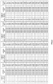
- a BS reports to a MS only the time slots allocated to the MS and the upper limit of transmission power, and the MS selects the coding rate, spreading factor and the number of bits of transmission data of the allocated time slots within the range of allowed transmission power, and reports the selected transmission parameters using the TB indexes (see FIG.1 ) provided on a per transport block size basis (hereinafter "TB size"), so that the BS performs receiving processing.
- TB size per transport block size basis
- TB size shows the number of transmission data bits before the CRC (Cyclic Redundancy Check) bits are added, and is derived from a combination of available transmission parameters.
- One TB size id associated with one coding rate and spreading factor.
- the M-ary modulation value is fixed and needs not be reported, so that, by reporting the TB size, the receiving side is able to acquire the number of information bits, the spreading factor and the coding rate.
- the BS determines the coding rate, spreading factor and the number of bits of transmission data, the BS is still able to control band allocation by including the TB size in band allocation information.
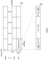
- FIG.4 shows the relationships between uplink time-frequency radio resources (UL) and their allocation units according to the present aspect.
- the period of time T RB is defined as one subframe with respect to the time axis, and one of the M frequency bands, resulting from dividing the system bandwidth BW SYS into M, is defined as the bandwidth BW RB with respect to the frequency axis.
- the time-frequency radio resources of period of time T RB ⁇ bandwidth BW RB are the minimum unit of radio resource allocation (RB: Resource Block) that can be allocated to one MS.
- the number of RB's to allocate to one MS varies between 1 and 4 on the frequency axis and the number of data symbols N TOTAL per subframe corresponding to the number of RB's to allocate, is defined in FIG.5 .
- the values defined here are only examples and other values or other numbers of RB's to allocate, may also be adopted.
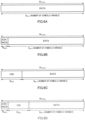
- the present aspect assumes a case where there are two pieces of control information, namely downlink ACK/NACK and downlink CQI, as L1/L2 control information to be multiplexed with UL user data. Therefore, when dynamic symbol allocation is performed according to the presence/absence of ACK/NACK and CQI, there are four ways of allocations as shown in FIG.6 , and the number of symbols allocated to user data ("DATA" in the figure) N DATA varies depending on the combinations of control information. That is, as shown in FIG.
- N DATA N TOTAL when the data allocated to one subframe is only user data
- N DATA N TOTAL - N ACK
- N DATA N TOTAL - N ACK
- FIG. 6C N TOTAL - N CQI
- FIG.6D N TOTAL - N ACK - N CQI
- control information such as band allocation requirement information and terminal transmission power information may be also used as L1/L2 control information. Furthermore, it is possible to allocate symbols to part of L1/L2 control information on a fixed basis whether or not it is present or absent, and dynamic symbol allocation may be carried out only between other L1/L2 control information and user data.
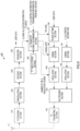
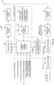
- Modulation section 102 converts the coded data sequence outputted from coding section 101 to modulated symbols according to predetermined modulation schemes (QPSK, 16QAM, 64QAM and so on) and outputs the modulated signal to RF transmitting section 103.
- Demodulation section 106 estimates and compensates the channel distortion of the baseband signal (received data symbol sequence) outputted from RF receiving section 105, identifies the signal points of the received data symbol sequence subjected to channel distortion compensation, through either of hard decision or soft decision suitable for the modulation of the data, based on the number of RB's and modulation scheme outputted from UL reception format determining section 112 (described later), and outputs the signal point decision result to decoding section 107.
- Decoding section 107 performs error correction processing on the signal point decision result outputted from demodulation section 106 based on the coding rate outputted from UL reception format determining section 112 and outputs the received data sequence to separation section 108.
- Separation section 108 separates the received data sequence outputted from decoding section 107 into UL user data and L1/L2 control information based on the TB size outputted from UL reception format determining section 112.
- TF table storage section 110 stores a table in which one TF index is assigned in association with a basic TF and a plurality of derived TF's. An appropriate TF index is selected from the stored table, the selected TF index is outputted to UL transport format determining section 111 and the parameters corresponding to the TF index are outputted to UL reception format determining section 112. Details of the TF table will be described later.
- UL reception format determining section 112 acquires the corresponding transmission parameters from TF table storage section 110 based on DL band allocation information outputted from a DL scheduler section (not shown), DL CQI allocation information outputted from a CQI scheduler section (not shown) and the TF index outputted from UL transport format determining section 111, determines the reception format for the UL user data transmitted from a MS on the uplink and determines the reception parameters required for the demodulation, such as the TB size, coding rate, the number of RB's and modulation scheme. The determined number of RB's and modulation scheme are outputted to demodulation section 106, the coding rate is outputted to decoding section 107 and the TB size is outputted to separation section 108.
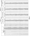
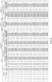
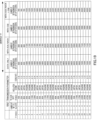
- the TF table is defined in advance as shown in FIG.8 .
- This TF table is stored as a table known to a BS and MS.
- This TF table provides combinations of two types of TF's, namely the basic TF's and derived TF's, and the basic TF's are assigned TF indexes .
- the basic TF's define, for example, the number of RB's to allocate, TB size, modulation scheme and coding rate for when user data alone is transmitted, as shown in FIG.8 .
- derived TF's define TB sizes that vary depending on the combinations of L1/L2 control information to be transmitted at the same time with the user data. That is, derived TF's are provided such that only the number of symbols to be assigned to user data varies, and, as for the other transmission parameters including the M-ary modulation value and coding rate, the same parameters are associated with the same TF index as the basic TF.
- a table is provide in which, in association with basic TF's, derived TF's are provided such that the rate matching by the number of symbols, which decreases and increases depending on whether or not there is L1/L2 control information (and which decreases in FIG.8 ), is controlled by TB size.
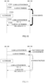
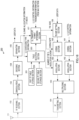
- FIG.9 is a block diagram showing a configuration of MS 150 according to aspect 1 of the present disclosure.
- RF receiving section 152 receives a signal transmitted from BS 100 via antenna 151, down-converts the received signal to a baseband signal and outputs the baseband signal to demodulation section 153.
- Demodulation section 153 estimates and compensates the channel distortion of the baseband signal (received data symbol sequence) outputted from RF receiving section 152, identifies the signal points of the received data symbol sequence subjected to channel distortion compensation through either hard decision or soft decision suitable for the modulation of the data, based on the modulation scheme, and outputs the signal point decision result to decoding section 154.
- Decoding section 154 performs error correction processing on the signal point decision result outputted from demodulation section 153 and outputs the received data sequence to separation section 155.
- Separation section 155 separates the received data sequence outputted from decoding section 154 into user data and UL band allocation information (TF index), and outputs the separated UL band allocation information to UL transport format determining section 157.
- TF index user data and UL band allocation information
- TF table storage section 156 stores the same table as the TF table of BS 100 and UL transport format determining section 157 reads the parameters associated with the TF index, from the stored table.
- Coding section 161 applies error correcting coding to L1/L2 control information at a predetermined coding rate, and outputs the coded data sequence to modulation section 162.
- Modulation section 162 converts the coded data sequence outputted from coding section 161 to modulated symbols according to a predetermined modulation scheme and outputs the modulated signal to multiplexing section 163.
- Multiplexing section 163 multiplexes the user data outputted from modulation section 160 and the L1/L2 control information outputted from modulation section 162, and outputs the multiplexed signal to RF transmitting section 164.
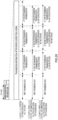
- TFI Transmission Time Intervals
- MS 150 which has received UL band allocation information acquires the number of RB's to allocate and the TB size of the basic TF, from the demodulated TF index. Furthermore, in a subframe in which UL user data is transmitted, MS 150 selects a TB size from the table shown in FIG.8 , according to the presence/absence and combinations of DL ACK/NACK or DL CQI transmission to be transmitted at the same time, performs coding and modulation of the transmission data of the TB size using the transmission parameters associated with the acquired TFI, time multiplexes necessary L1/L2 control information and then carries out uplink transmission.
- BS 100 since the same BS 100 performs the downlink band allocation as well, when performing UL scheduling, if MS 150 receives DL band allocation information correctly, BS 100 knows in advance that DL ACK/NACK are multiplexed upon the same time and only reports the TFI of the basic TF, and, in many cases, MS 150 also performs UL transmission in the TB size intended by BS 100.
- the number of bits for transport format for scheduling information can be reduced, so that uplink frequency utilization efficiency is improved without increasing overhead for control information.
- rate matching is controlled by changing the coding rate, so that, even when control information is multiplexed upon the same time, the number of information bits to be transmitted does not change and the transmission data rate (i.e. transmission rate) is effectively maintained.
- UL scheduler section 401 is provided with first TF table storage section 402, second TF table storage section 403, table selection section 404 and UL transport format determining section 111.
- TF table storage section 402 stores the first table shown in FIG.8 , FIG.12 , FIG.13 , FIG.14 and so on, and second TF table storage section 403 stores a second table in which derived TF's are provided with different number of retransmission bits depending on the combinations of L1/L2 control information.
- FIG.18 is a block diagram showing a configuration of MS 450 according to aspect 5 of the present disclosure.
- FIG.18 differs from FIG.9 in that a plurality of TF table storage sections 451 and 452 and table selection section 453 are added.
- first TF table storage section 451 stores the first table shown in FIG.8 , FIG.12 , FIG.13 , FIG.14 and so on
- second TF table storage section 452 stores a second table in which the number of bits transmitted upon retransmission is set in derived TF's according to the combinations of L1/L2 control information.
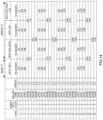
- FIG.19 shows a TF table according to aspect 5 of the present disclosure.
- the derived TF's are provided such that the number of retransmission bits varies depending on the combinations of L1/L2 control information.
- the number of retransmission bits varies between retransmissions, for example, more specifically, the following adjustment may be carried out.
- retransmission may be performed from the bit position where transmission takes place when L1/L2 control information is not multiplexed.
- the position the redundant bits start being transmitted, may be shared in advance between the BS and MS .
- the rate matching between retransmissions is controlled by adjusting the number of redundant bits to be retransmitted and the redundant bit selection pattern, so that, even when L1/L2 control information is multiplexed upon retransmission, redundant bits can be transmitted effectively.
- Aspect 5 is especially effective in synchronous HARQ where UL band allocation information is not reported on the downlink upon retransmissions.
- the present aspect has explained the details of adjustment for when the number of retransmission bits varies upon retransmission assuming a HARQ system based on the IR scheme, and adjustment for HARQ applied to the HSDPA (High Speed Downlink Packet Access) system described in Non-Patent Document 3, is as follows. That is, the rate matching and transmission bits upon retransmission are determined by the parameter "s" and parameter "r" of the RV (Redundancy Version) variable, which is reported in band allocation information.
- RV Redundancy Version
- parameter s is a mode in which parity bits are preferentially retransmitted, so that parity bits are selected as bits to be retransmitted with respect to the number of retransmission bits shown in the TF table and systematic bits are further transmitted if there are a sufficient number of retransmission bits.
- the present disclosure is not limited to this and may also be adapted to switch more tables.
- the TF table upon retransmission may be switched for every retransmission count.
- Each function block employed in the description of each of the aforementioned aspects may typically be implemented as an LSI constituted by an integrated circuit . These may be individual chips or partially or totally contained on a single chip. "LSI” is adopted here but this may also be referred to as “IC,” “system LSI,” “super LSI,” or “ultra LSI” depending on differing extents of integration.
- circuit integration is not limited to LSI's, and implementation using dedicated circuitry or general purpose processors is also possible.
- LSI manufacture utilization of a programmable FPGA (Field Programmable Gate Array) or a reconfigurable processor where connections and settings of circuit cells within an LSI can be reconfigured is also possible.
- FPGA Field Programmable Gate Array
- the radio transmitting apparatus and radio transmission method according to the present disclosure can improve throughputs of a downlink and uplink even when performing dynamic symbol allocation and is applicable, for example, to a 3GPP LTE radio communication system.
Landscapes
- Engineering & Computer Science (AREA)
- Computer Networks & Wireless Communication (AREA)
- Signal Processing (AREA)
- Quality & Reliability (AREA)
- Mobile Radio Communication Systems (AREA)
- Detection And Prevention Of Errors In Transmission (AREA)
- Digital Transmission Methods That Use Modulated Carrier Waves (AREA)
- Communication Control (AREA)
Applications Claiming Priority (5)
| Application Number | Priority Date | Filing Date | Title |
|---|---|---|---|
| JP2006140462 | 2006-05-19 | ||
| EP07743693.9A EP2019559B1 (en) | 2006-05-19 | 2007-05-18 | Radio transmission device and radio transmission method |
| EP14200199.9A EP2866364B1 (en) | 2006-05-19 | 2007-05-18 | Radio transmission device and radio transmission method |
| EP19196910.4A EP3606245B1 (en) | 2006-05-19 | 2007-05-18 | Radio transmission device and radio transmission method |
| PCT/JP2007/060258 WO2007136002A1 (ja) | 2006-05-19 | 2007-05-18 | 無線送信装置及び無線送信方法 |
Related Parent Applications (4)
| Application Number | Title | Priority Date | Filing Date |
|---|---|---|---|
| EP19196910.4A Division EP3606245B1 (en) | 2006-05-19 | 2007-05-18 | Radio transmission device and radio transmission method |
| EP19196910.4A Division-Into EP3606245B1 (en) | 2006-05-19 | 2007-05-18 | Radio transmission device and radio transmission method |
| EP14200199.9A Division EP2866364B1 (en) | 2006-05-19 | 2007-05-18 | Radio transmission device and radio transmission method |
| EP07743693.9A Division EP2019559B1 (en) | 2006-05-19 | 2007-05-18 | Radio transmission device and radio transmission method |
Publications (4)
| Publication Number | Publication Date |
|---|---|
| EP4362592A2 EP4362592A2 (en) | 2024-05-01 |
| EP4362592A3 EP4362592A3 (en) | 2024-07-10 |
| EP4362592B1 true EP4362592B1 (en) | 2025-07-02 |
| EP4362592C0 EP4362592C0 (en) | 2025-07-02 |
Family
ID=38723313
Family Applications (4)
| Application Number | Title | Priority Date | Filing Date |
|---|---|---|---|
| EP24164180.2A Active EP4362592B1 (en) | 2006-05-19 | 2007-05-18 | Radio transmission device and radio transmission method |
| EP14200199.9A Active EP2866364B1 (en) | 2006-05-19 | 2007-05-18 | Radio transmission device and radio transmission method |
| EP07743693.9A Active EP2019559B1 (en) | 2006-05-19 | 2007-05-18 | Radio transmission device and radio transmission method |
| EP19196910.4A Active EP3606245B1 (en) | 2006-05-19 | 2007-05-18 | Radio transmission device and radio transmission method |
Family Applications After (3)
| Application Number | Title | Priority Date | Filing Date |
|---|---|---|---|
| EP14200199.9A Active EP2866364B1 (en) | 2006-05-19 | 2007-05-18 | Radio transmission device and radio transmission method |
| EP07743693.9A Active EP2019559B1 (en) | 2006-05-19 | 2007-05-18 | Radio transmission device and radio transmission method |
| EP19196910.4A Active EP3606245B1 (en) | 2006-05-19 | 2007-05-18 | Radio transmission device and radio transmission method |
Country Status (12)
| Country | Link |
|---|---|
| US (7) | US8488692B2 (enExample) |
| EP (4) | EP4362592B1 (enExample) |
| JP (3) | JP4654294B2 (enExample) |
| KR (2) | KR101365374B1 (enExample) |
| CN (2) | CN101449501B (enExample) |
| BR (1) | BRPI0712598B1 (enExample) |
| ES (3) | ES2983459T3 (enExample) |
| IN (1) | IN2014MN02527A (enExample) |
| MX (1) | MX2008014738A (enExample) |
| PL (1) | PL2866364T3 (enExample) |
| RU (2) | RU2454807C2 (enExample) |
| WO (1) | WO2007136002A1 (enExample) |
Families Citing this family (53)
| Publication number | Priority date | Publication date | Assignee | Title |
|---|---|---|---|---|
| US20070149132A1 (en) | 2005-12-22 | 2007-06-28 | Junyl Li | Methods and apparatus related to selecting control channel reporting formats |
| IN2014MN02527A (enExample) * | 2006-05-19 | 2015-07-17 | Panasonic Ip Corp America | |
| JP5047270B2 (ja) * | 2007-03-01 | 2012-10-10 | 株式会社エヌ・ティ・ティ・ドコモ | 基地局装置 |
| KR101494002B1 (ko) * | 2007-06-11 | 2015-02-16 | 삼성전자주식회사 | 이동통신 시스템에서 자원 할당 및 그에 따른 수신 장치 및방법 |
| US8412209B2 (en) * | 2007-06-18 | 2013-04-02 | Motorola Mobility Llc | Use of the physical uplink control channel in a 3rd generation partnership project communication system |
| EP2464042B1 (en) | 2007-06-19 | 2014-08-06 | Panasonic Intellectual Property Corporation of America | Channel arrangement method and radio communcation base station device |
| RU2485696C2 (ru) | 2007-06-19 | 2013-06-20 | Нокиа Сименс Нетворкс Ой | Сигнализация восходящей линии связи адаптивного транспортного формата для не связанных с данными управляющих сигналов обратной связи |
| WO2009001465A1 (ja) * | 2007-06-28 | 2008-12-31 | Panasonic Corporation | 送信装置、送信方法、受信装置、及び受信方法 |
| US20090067603A1 (en) * | 2007-09-07 | 2009-03-12 | Avaya Technology Llc | Pre-arranged, mutually agreed to, VoIP or VoIM call |
| KR100932555B1 (ko) * | 2007-12-03 | 2009-12-17 | 한국전자통신연구원 | 이동통신 시스템의 자원할당 방법 |
| JP5061892B2 (ja) | 2007-12-28 | 2012-10-31 | 富士通株式会社 | 無線通信システムにおける信号多重方法、送信局及び受信局 |
| US8098759B2 (en) * | 2008-01-04 | 2012-01-17 | Panasonic Corporation | Radio transmitting device and radio transmitting method |
| WO2009096757A2 (ko) * | 2008-02-03 | 2009-08-06 | Lg Electronics Inc. | 무선 통신 시스템에서 cqi 전송 방법 |
| MX2010008596A (es) | 2008-02-04 | 2010-08-31 | Samsung Electronics Co Ltd | Multiplexion de control y datos en sistemas de comunicacion. |
| JP5041597B2 (ja) * | 2008-02-27 | 2012-10-03 | Kddi株式会社 | 無線リソースの割り当てをスケジューリングする基地局、方法及びプログラム |
| JP5115802B2 (ja) * | 2008-03-11 | 2013-01-09 | 富士通株式会社 | スケジューリング装置、スケジューリング方法、およびプログラム |
| KR101162450B1 (ko) * | 2008-03-21 | 2012-07-05 | 인터디지탈 패튼 홀딩스, 인크 | 피드백 시그널링의 방법 및 장치 |
| US8179783B2 (en) * | 2008-08-13 | 2012-05-15 | Telefonaktiebolaget L M Ericsson (Publ) | System and method of modulation and coding scheme adjustment for a LTE shared data channel |
| US8730933B2 (en) * | 2008-09-18 | 2014-05-20 | Qualcomm Incorporated | Method and apparatus for multiplexing data and reference signal in a wireless communication system |
| US8295779B2 (en) | 2008-10-31 | 2012-10-23 | Interdigital Patent Holdings, Inc. | Method and apparatus for wireless transmissions using multiple uplink carriers |
| US8422439B2 (en) * | 2008-12-31 | 2013-04-16 | Motorola Mobility Llc | Apparatus and method for communicating control information over a data channel in the absence of user data |
| US20100184450A1 (en) * | 2009-01-16 | 2010-07-22 | Xuemin Sherman Chen | Method and system for controlling parameters of a communication channel between a femtocell and a cellular enabled communication device |
| JP4898858B2 (ja) | 2009-03-02 | 2012-03-21 | パナソニック株式会社 | 符号化器、復号化器及び符号化方法 |
| JP5325982B2 (ja) * | 2009-06-19 | 2013-10-23 | Kddi株式会社 | 参照信号送信スケジューリング装置及び参照信号送信スケジューリング方法 |
| US9288026B2 (en) * | 2009-06-22 | 2016-03-15 | Qualcomm Incorporated | Transmission of reference signal on non-contiguous clusters of resources |
| US9014138B2 (en) * | 2009-08-07 | 2015-04-21 | Blackberry Limited | System and method for a virtual carrier for multi-carrier and coordinated multi-point network operation |
| CN102013938B (zh) * | 2009-12-07 | 2012-07-04 | 华为技术有限公司 | 传输上行控制信息的方法和装置 |
| JP5573167B2 (ja) * | 2010-01-06 | 2014-08-20 | 日本電気株式会社 | コンテンツ共有システム,コンテンツ共有方法及びプログラム |
| JP5337843B2 (ja) * | 2011-06-29 | 2013-11-06 | アンリツ株式会社 | 移動通信端末試験装置及び移動通信端末試験方法 |
| US8842641B2 (en) * | 2011-08-12 | 2014-09-23 | Telefonaktiebolaget L M Ericsson (Publ) | RAKE resource multiplexing for enhanced uplink data services |
| US20150326305A1 (en) * | 2012-05-01 | 2015-11-12 | Metanoia Communications Inc. | Framing Mechanism For Time-Division-Duplex OFDM Communication Systems |
| JP5445624B2 (ja) * | 2012-06-08 | 2014-03-19 | 富士通株式会社 | 送信局及び受信局 |
| US9144080B2 (en) | 2012-11-07 | 2015-09-22 | Telefonaktiebolaget L M Ericsson (Publ) | Selecting transmission parameters for downlink transmissions based on retransmission rates |
| CN105122700B (zh) * | 2012-12-10 | 2018-05-11 | Lg电子株式会社 | 在支持超高频的无线接入系统中发送系统信息的方法及支持该方法的装置 |
| GB2513122A (en) * | 2013-04-15 | 2014-10-22 | Vodafone Intellectual Property Licensing Ltd | Uplink control channel overhead reduction |
| JP2016025560A (ja) * | 2014-07-23 | 2016-02-08 | 株式会社デンソー | データ生成装置およびデータ処理装置 |
| US9960789B2 (en) | 2015-01-28 | 2018-05-01 | Nec Corporation | Optical transmitter, optical communication system, and optical communication method |
| KR101755224B1 (ko) * | 2015-06-09 | 2017-07-11 | 한국철도기술연구원 | 인덱스 코딩과 통계적 특성을 이용한 데이터 재전송 시스템 및 방법 |
| EP3376946A1 (en) | 2015-11-16 | 2018-09-26 | Hill-Rom Services, Inc. | Incontinence detection systems for hospital beds |
| CN107306453B (zh) * | 2016-04-25 | 2019-12-17 | 华为技术有限公司 | 一种生成传输块的方法和装置 |
| CN109792309B (zh) | 2016-08-10 | 2021-12-31 | 瑞典爱立信有限公司 | 传输块内的校验位置 |
| US10492084B2 (en) | 2016-10-10 | 2019-11-26 | Microsoft Technology Licensing, Llc | Collaborative communications |
| WO2018230992A1 (ko) | 2017-06-15 | 2018-12-20 | 삼성전자 주식회사 | 통신 또는 방송 시스템에서 채널 부호화 및 복호화를 수행하는 방법 및 장치 |
| KR102414531B1 (ko) * | 2017-06-15 | 2022-06-30 | 삼성전자 주식회사 | 통신 또는 방송 시스템에서 채널 부호화/복호화 방법 및 장치 |
| US10686575B2 (en) | 2017-06-23 | 2020-06-16 | Samsung Electronics Co., Ltd. | Method and apparatus for wireless communication using modulation, coding schemes, and transport block sizes |
| JP7058087B2 (ja) * | 2017-07-03 | 2022-04-21 | シャープ株式会社 | 端末装置、基地局装置、および、通信方法 |
| BR112020003426A2 (pt) * | 2017-08-24 | 2020-08-25 | Telefonaktiebolaget Lm Ericsson (Publ) | segmentação de bloco de código para novo rádio 3gpp |
| US11451333B2 (en) * | 2017-10-03 | 2022-09-20 | Telefonaktiebolaget L M Ericsson (Publ) | TBS determination with multiple base graphs |
| CN110034848B (zh) * | 2018-01-12 | 2021-03-23 | 华为技术有限公司 | 一种信息传输方法和装置 |
| US11363593B2 (en) * | 2019-03-08 | 2022-06-14 | Qualcomm Incorporated | Waveform generation in millimeter wave band with time domain implementation |
| CN110211416B (zh) * | 2019-06-06 | 2021-12-21 | 广域铭岛数字科技有限公司 | 物联网智能车库的信息传输方法及系统 |
| US11509420B2 (en) * | 2020-10-06 | 2022-11-22 | Qualcomm Incorporated | Methods and apparatus for FEC rate adaptation |
| US20250105955A1 (en) * | 2023-09-22 | 2025-03-27 | Qualcomm Incorporated | Transport block size calculation for orthogonal cover coding and sub-physical-resource-block allocation for physical uplink shared channel |
Family Cites Families (37)
| Publication number | Priority date | Publication date | Assignee | Title |
|---|---|---|---|---|
| FI107220B (fi) * | 1998-11-06 | 2001-06-15 | Nokia Networks Oy | Menetelmä kantajien ominaisuuksien hallitsemiseksi |
| JP4160072B2 (ja) | 1998-11-25 | 2008-10-01 | 株式会社半導体エネルギー研究所 | 半導体装置の作製方法 |
| US6850759B2 (en) | 2001-02-22 | 2005-02-01 | Telefonaktiebolaget Lm Ericsson (Publ) | Reducing signaling in RNSAP protocol upon cell change in cellular telecommunications network |
| GB2377586B (en) * | 2001-07-06 | 2005-06-29 | Ipwireless Inc | System and method for channel transport format allocation in a wireless communication system |
| KR100450938B1 (ko) * | 2001-10-05 | 2004-10-02 | 삼성전자주식회사 | 고속 순방향 패킷 접속 방식을 사용하는 통신 시스템에서트랜스포트 블록 셋 크기 정보를 송수신하는 장치 및 방법 |
| US6747958B2 (en) * | 2001-11-13 | 2004-06-08 | Qualcomm, Incorporated | Transport format combination selection for compressed mode in a W-CDMA system |
| KR100754552B1 (ko) * | 2001-12-28 | 2007-09-05 | 삼성전자주식회사 | 고속 순방향 패킷 접속 방식을 사용하는 통신 시스템에서고속 공통 제어 채널 송수신 장치 및 방법 |
| US9270410B2 (en) * | 2002-04-22 | 2016-02-23 | Texas Instruments Incorporated | MIMO PGRC system and method |
| US7149245B2 (en) | 2002-04-29 | 2006-12-12 | Lucent Technologies Inc. | Link adaption in enhanced general packet radio service networks |
| KR100876765B1 (ko) * | 2002-05-10 | 2009-01-07 | 삼성전자주식회사 | 이동 통신 시스템에서 데이터 재전송 장치 및 방법 |
| EP1533926B1 (en) | 2002-09-12 | 2017-12-06 | Panasonic Intellectual Property Corporation of America | Radio transmission device, radio reception device, and method for selecting transmission cancel subcarriers |
| US7289452B2 (en) | 2002-10-24 | 2007-10-30 | Nokia Corporation | Transport block size (TBS) signaling enhancement |
| JP3796212B2 (ja) * | 2002-11-20 | 2006-07-12 | 松下電器産業株式会社 | 基地局装置及び送信割り当て制御方法 |
| US7408902B2 (en) * | 2003-02-13 | 2008-08-05 | Interdigital Technology Corporation | Method of using a radio network controller for controlling data bit rates to maintain the quality of radio links |
| US7688798B2 (en) * | 2003-02-14 | 2010-03-30 | Nokia Siemens Networks Gmbh & Co. Kg | Data transmission method |
| KR100678182B1 (ko) * | 2003-08-20 | 2007-02-02 | 삼성전자주식회사 | 비동기 광대역 부호분할 다중접속 시스템에서 상향링크 패킷 데이터 서비스 방법 및 장치 |
| KR100995031B1 (ko) | 2003-10-01 | 2010-11-19 | 엘지전자 주식회사 | 다중입력 다중출력 시스템에 적용되는 신호 전송 제어 방법 |
| KR100981580B1 (ko) | 2003-12-23 | 2010-09-10 | 삼성전자주식회사 | 8 개 이하의 송신 안테나를 사용하는 차등 시공간 블록 부호 송수신 장치 |
| US7333556B2 (en) * | 2004-01-12 | 2008-02-19 | Intel Corporation | System and method for selecting data rates to provide uniform bit loading of subcarriers of a multicarrier communication channel |
| US20050237932A1 (en) | 2004-04-23 | 2005-10-27 | Jung-Tao Liu | Method and system for rate-controlled mode wireless communications |
| JP4421935B2 (ja) * | 2004-04-30 | 2010-02-24 | 株式会社エヌ・ティ・ティ・ドコモ | 無線基地局装置及び無線通信制御方法 |
| KR100754722B1 (ko) * | 2004-05-12 | 2007-09-03 | 삼성전자주식회사 | 무선 통신 시스템에서 채널 상태 정보를 이용한 데이터송수신 장치 및 방법 |
| WO2005125259A1 (ja) * | 2004-06-17 | 2005-12-29 | Ntt Docomo, Inc. | 伝送速度制御方法、送信電力制御方法、送信電力比制御方法、移動通信システム、移動局及び無線基地局 |
| EP1617606A1 (en) * | 2004-07-16 | 2006-01-18 | Matsushita Electric Industrial Co., Ltd. | Scheduling mode switching for uplink transmissions |
| JP4355631B2 (ja) * | 2004-08-11 | 2009-11-04 | 株式会社エヌ・ティ・ティ・ドコモ | 移動通信システム及び移動局 |
| CN1756254B (zh) * | 2004-09-29 | 2011-01-12 | 上海贝尔阿尔卡特股份有限公司 | 无线链路控制层的分段方法 |
| GB0421663D0 (en) * | 2004-09-29 | 2004-10-27 | Nokia Corp | Transmitting data in a wireless network |
| ATE391376T1 (de) * | 2004-10-01 | 2008-04-15 | Matsushita Electric Industrial Co Ltd | Dienstgüte-bewusste ablaufsteuerung für aufwärtsübertragungen über zugeordneten kanälen |
| US8826328B2 (en) * | 2004-11-12 | 2014-09-02 | Opentv, Inc. | Communicating primary content streams and secondary content streams including targeted advertising to a remote unit |
| US20060281417A1 (en) | 2005-05-10 | 2006-12-14 | Ntt Docomo, Inc. | Transmission rate control method and mobile station |
| US7403470B2 (en) * | 2005-06-13 | 2008-07-22 | Qualcomm Incorporated | Communications system, methods and apparatus |
| US8731562B2 (en) * | 2005-08-30 | 2014-05-20 | Telefonaktiebolaget L M Ericsson (Publ) | Detection of control messages for HSDPA |
| CN100486252C (zh) * | 2005-10-18 | 2009-05-06 | 中兴通讯股份有限公司 | 支持多载波高速下行分组接入的数据并行调度系统及方法 |
| US20070171849A1 (en) | 2006-01-03 | 2007-07-26 | Interdigital Technology Corporation | Scheduling channel quality indicator and acknowledgement/negative acknowledgement feedback |
| US7903614B2 (en) * | 2006-04-27 | 2011-03-08 | Interdigital Technology Corporation | Method and apparatus for selecting link adaptation parameters for CDMA-based wireless communication systems |
| IN2014MN02527A (enExample) * | 2006-05-19 | 2015-07-17 | Panasonic Ip Corp America | |
| US20120018883A1 (en) | 2007-09-13 | 2012-01-26 | Geng-Shin Shen | Conductive structure for a semiconductor integrated circuit |
-
2007
- 2007-05-18 IN IN2527MUN2014 patent/IN2014MN02527A/en unknown
- 2007-05-18 JP JP2008516673A patent/JP4654294B2/ja active Active
- 2007-05-18 US US12/301,441 patent/US8488692B2/en active Active
- 2007-05-18 MX MX2008014738A patent/MX2008014738A/es active IP Right Grant
- 2007-05-18 PL PL14200199T patent/PL2866364T3/pl unknown
- 2007-05-18 EP EP24164180.2A patent/EP4362592B1/en active Active
- 2007-05-18 EP EP14200199.9A patent/EP2866364B1/en active Active
- 2007-05-18 ES ES19196910T patent/ES2983459T3/es active Active
- 2007-05-18 ES ES14200199T patent/ES2773861T3/es active Active
- 2007-05-18 EP EP07743693.9A patent/EP2019559B1/en active Active
- 2007-05-18 WO PCT/JP2007/060258 patent/WO2007136002A1/ja not_active Ceased
- 2007-05-18 ES ES24164180T patent/ES3039607T3/es active Active
- 2007-05-18 KR KR1020117029441A patent/KR101365374B1/ko active Active
- 2007-05-18 EP EP19196910.4A patent/EP3606245B1/en active Active
- 2007-05-18 CN CN2007800180712A patent/CN101449501B/zh active Active
- 2007-05-18 KR KR1020087028281A patent/KR101365373B1/ko active Active
- 2007-05-18 CN CN201110162006.5A patent/CN102223205B/zh active Active
- 2007-05-18 RU RU2008150306/07A patent/RU2454807C2/ru active
- 2007-05-18 BR BRPI0712598-4A patent/BRPI0712598B1/pt active IP Right Grant
-
2010
- 2010-12-17 JP JP2010281700A patent/JP5001420B2/ja active Active
-
2012
- 2012-03-21 RU RU2012110822/07A patent/RU2494549C1/ru active
- 2012-05-16 JP JP2012112219A patent/JP5504303B2/ja active Active
-
2013
- 2013-06-14 US US13/918,654 patent/US9432972B2/en active Active
-
2016
- 2016-07-21 US US15/216,641 patent/US10827466B2/en active Active
-
2020
- 2020-09-29 US US17/037,518 patent/US11470583B2/en active Active
-
2022
- 2022-08-30 US US17/899,352 patent/US11765726B2/en active Active
-
2023
- 2023-08-08 US US18/446,193 patent/US12096436B2/en active Active
-
2024
- 2024-08-05 US US18/794,805 patent/US20240397514A1/en active Pending
Also Published As
Similar Documents
| Publication | Publication Date | Title |
|---|---|---|
| US11765726B2 (en) | Radio transmission device and radio transmission method | |
| JP5061095B2 (ja) | 無線通信システム、無線送信装置、および再送方法 | |
| JP3561510B2 (ja) | 基地局装置及びパケット伝送方法 | |
| EP1835631A1 (en) | Control channel transmission method, base station and terminal |
Legal Events
| Date | Code | Title | Description |
|---|---|---|---|
| PUAI | Public reference made under article 153(3) epc to a published international application that has entered the european phase |
Free format text: ORIGINAL CODE: 0009012 |
|
| STAA | Information on the status of an ep patent application or granted ep patent |
Free format text: STATUS: REQUEST FOR EXAMINATION WAS MADE |
|
| 17P | Request for examination filed |
Effective date: 20240318 |
|
| AC | Divisional application: reference to earlier application |
Ref document number: 2019559 Country of ref document: EP Kind code of ref document: P Ref document number: 2866364 Country of ref document: EP Kind code of ref document: P Ref document number: 3606245 Country of ref document: EP Kind code of ref document: P |
|
| AK | Designated contracting states |
Kind code of ref document: A2 Designated state(s): AT BE BG CH CY CZ DE DK EE ES FI FR GB GR HU IE IS IT LI LT LU LV MC MT NL PL PT RO SE SI SK TR |
|
| REG | Reference to a national code |
Ref country code: DE Ref legal event code: R079 Ref document number: 602007061993 Country of ref document: DE Free format text: PREVIOUS MAIN CLASS: H04W0072126800 Ipc: H04J0001000000 Ref country code: DE Ref legal event code: R079 Free format text: PREVIOUS MAIN CLASS: H04W0072126800 Ipc: H04J0001000000 |
|
| PUAL | Search report despatched |
Free format text: ORIGINAL CODE: 0009013 |
|
| AK | Designated contracting states |
Kind code of ref document: A3 Designated state(s): AT BE BG CH CY CZ DE DK EE ES FI FR GB GR HU IE IS IT LI LT LU LV MC MT NL PL PT RO SE SI SK TR |
|
| RIC1 | Information provided on ipc code assigned before grant |
Ipc: H04W 72/1268 20230101ALN20240606BHEP Ipc: H04L 1/1607 20230101ALN20240606BHEP Ipc: H04W 72/04 20230101ALI20240606BHEP Ipc: H04L 1/00 20060101ALI20240606BHEP Ipc: H04L 27/38 20060101ALI20240606BHEP Ipc: H04L 27/36 20060101ALI20240606BHEP Ipc: H04L 27/22 20060101ALI20240606BHEP Ipc: H04L 27/20 20060101ALI20240606BHEP Ipc: H04L 1/16 20230101ALI20240606BHEP Ipc: H04J 1/00 20060101AFI20240606BHEP |
|
| GRAP | Despatch of communication of intention to grant a patent |
Free format text: ORIGINAL CODE: EPIDOSNIGR1 |
|
| STAA | Information on the status of an ep patent application or granted ep patent |
Free format text: STATUS: GRANT OF PATENT IS INTENDED |
|
| RIC1 | Information provided on ipc code assigned before grant |
Ipc: H04W 72/1268 20230101ALN20250324BHEP Ipc: H04L 1/1607 20230101ALN20250324BHEP Ipc: H04W 72/04 20230101ALI20250324BHEP Ipc: H04L 1/00 20060101ALI20250324BHEP Ipc: H04L 27/38 20060101ALI20250324BHEP Ipc: H04L 27/36 20060101ALI20250324BHEP Ipc: H04L 27/22 20060101ALI20250324BHEP Ipc: H04L 27/20 20060101ALI20250324BHEP Ipc: H04L 1/16 20230101ALI20250324BHEP Ipc: H04J 1/00 20060101AFI20250324BHEP |
|
| INTG | Intention to grant announced |
Effective date: 20250403 |
|
| GRAS | Grant fee paid |
Free format text: ORIGINAL CODE: EPIDOSNIGR3 |
|
| GRAA | (expected) grant |
Free format text: ORIGINAL CODE: 0009210 |
|
| STAA | Information on the status of an ep patent application or granted ep patent |
Free format text: STATUS: THE PATENT HAS BEEN GRANTED |
|
| AC | Divisional application: reference to earlier application |
Ref document number: 2019559 Country of ref document: EP Kind code of ref document: P Ref document number: 2866364 Country of ref document: EP Kind code of ref document: P Ref document number: 3606245 Country of ref document: EP Kind code of ref document: P |
|
| AK | Designated contracting states |
Kind code of ref document: B1 Designated state(s): AT BE BG CH CY CZ DE DK EE ES FI FR GB GR HU IE IS IT LI LT LU LV MC MT NL PL PT RO SE SI SK TR |
|
| REG | Reference to a national code |
Ref country code: GB Ref legal event code: FG4D |
|
| REG | Reference to a national code |
Ref country code: CH Ref legal event code: EP |
|
| REG | Reference to a national code |
Ref country code: DE Ref legal event code: R096 Ref document number: 602007061993 Country of ref document: DE |
|
| REG | Reference to a national code |
Ref country code: IE Ref legal event code: FG4D |
|
| U01 | Request for unitary effect filed |
Effective date: 20250801 |
|
| U07 | Unitary effect registered |
Designated state(s): AT BE BG DE DK EE FI FR IT LT LU LV MT NL PT RO SE SI Effective date: 20250812 |
|
| PG25 | Lapsed in a contracting state [announced via postgrant information from national office to epo] |
Ref country code: IS Free format text: LAPSE BECAUSE OF FAILURE TO SUBMIT A TRANSLATION OF THE DESCRIPTION OR TO PAY THE FEE WITHIN THE PRESCRIBED TIME-LIMIT Effective date: 20251102 |
|
| PG25 | Lapsed in a contracting state [announced via postgrant information from national office to epo] |
Ref country code: GR Free format text: LAPSE BECAUSE OF FAILURE TO SUBMIT A TRANSLATION OF THE DESCRIPTION OR TO PAY THE FEE WITHIN THE PRESCRIBED TIME-LIMIT Effective date: 20251003 |
|
| PG25 | Lapsed in a contracting state [announced via postgrant information from national office to epo] |
Ref country code: CZ Free format text: LAPSE BECAUSE OF FAILURE TO SUBMIT A TRANSLATION OF THE DESCRIPTION OR TO PAY THE FEE WITHIN THE PRESCRIBED TIME-LIMIT Effective date: 20250702 |
|
| PG25 | Lapsed in a contracting state [announced via postgrant information from national office to epo] |
Ref country code: PL Free format text: LAPSE BECAUSE OF FAILURE TO SUBMIT A TRANSLATION OF THE DESCRIPTION OR TO PAY THE FEE WITHIN THE PRESCRIBED TIME-LIMIT Effective date: 20250702 |